


Verilog 4 対 1 マルチプレクサ/Mux
マルチプレクサまたはマルチプレクサとは?
マルチプレクサまたは mux つまり、選択信号に基づいて、N 入力の 1 つから出力にデータを転送するデジタル要素です。以下に示すケースは、N が 4 に等しい場合です。たとえば、4 ビット マルチプレクサには、それぞれ 4 ビットの N 入力があり、選択信号を使用して各入力を出力に転送できます。
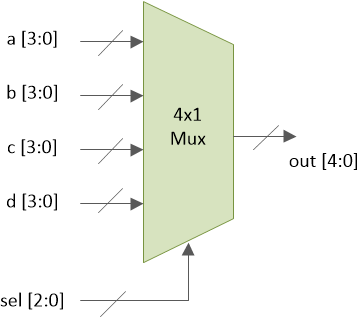
sel は 2 ビット入力で、4 つの値を持つことができます。選択行の各値により、入力の 1 つを出力ピン出力に送信できます。
	sel     a     b     c     d     out
	 0     3    7     1     9    3
	 1      3    7    1     9    7
	 2      3     7    1    9    1
	 3      3     7     1    9   9
4x1 マルチプレクサは複数の方法で実装できます。ここでは、最も一般的な 2 つの方法を紹介します。
assignの使用 声明caseの使用 声明
assign の使用 声明
module mux_4to1_assign ( input [3:0] a,                 // 4-bit input called a
                         input [3:0] b,                 // 4-bit input called b
                         input [3:0] c,                 // 4-bit input called c
                         input [3:0] d,                 // 4-bit input called d
                         input [1:0] sel,               // input sel used to select between a,b,c,d
                         output [3:0] out);             // 4-bit output based on input sel

   // When sel[1] is 0, (sel[0]? b:a) is selected and when sel[1] is 1, (sel[0] ? d:c) is taken
   // When sel[0] is 0, a is sent to output, else b and when sel[0] is 0, c is sent to output, else d
   assign out = sel[1] ? (sel[0] ? d : c) : (sel[0] ? b : a);

endmodule
mux_4x1_assign というモジュール 4 つの 4 ビット データ入力、1 つの 2 ビット選択入力、および 1 つの 4 ビット データ出力があります。マルチプレクサは、assign を使用した選択信号 sel に基づいて、a、b、c、または d のいずれかを選択します。
case の使用 声明
シグナル出力は reg として宣言されていることに注意してください プロシージャルで使用されるため、タイプします always のようなブロック .
module mux_4to1_case ( input [3:0] a,                 // 4-bit input called a
                       input [3:0] b,                 // 4-bit input called b
                       input [3:0] c,                 // 4-bit input called c
                       input [3:0] d,                 // 4-bit input called d
                       input [1:0] sel,               // input sel used to select between a,b,c,d
                       output reg [3:0] out);         // 4-bit output based on input sel

   // This always block gets executed whenever a/b/c/d/sel changes value
   // When that happens, based on value in sel, output is assigned to either a/b/c/d
   always @ (a or b or c or d or sel) begin
      case (sel)
         2'b00 : out <= a;
         2'b01 : out <= b;
         2'b10 : out <= c;
         2'b11 : out <= d;
      endcase
   end
endmodule
mux_4x1_case というモジュール 4 つの 4 ビット データ入力、1 つの 2 ビット選択入力、および 1 つの 4 ビット データ出力があります。マルチプレクサは、case を使用した選択信号 sel に基づいて、a、b、c、または d のいずれかを選択します。
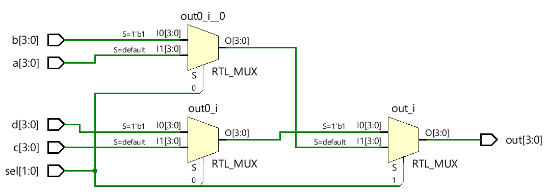
ハードウェア回路図
下の図に示すように、両方のタイプのマルチプレクサ モデルが同じハードウェアに合成されます。
テストベンチ
module tb_4to1_mux;

   // Declare internal reg variables to drive design inputs
   // Declare wire signals to collect design output
   // Declare other internal variables used in testbench
   reg [3:0] a;
   reg [3:0] b;
   reg [3:0] c;
   reg [3:0] d;
   wire [3:0] out;
   reg [1:0] sel;
   integer i;

   // Instantiate one of the designs, in this case, we have used the design with case statement
   // Connect testbench variables declared above with those in the design
   mux_4to1_case  mux0 (   .a (a),
                           .b (b),
                           .c (c),
                           .d (d),
                           .sel (sel),
                           .out (out));

   // This initial block is the stimulus
   initial begin
      // Launch a monitor in background to display values to log whenever a/b/c/d/sel/out changes
      $monitor ("[%0t] sel=0x%0h a=0x%0h b=0x%0h c=0x%0h d=0x%0h out=0x%0h", $time, sel, a, b, c, d, out);

   	  // 1. At time 0, drive random values to a/b/c/d and keep sel = 0
      sel <= 0;
      a <= $random;
      b <= $random;
      c <= $random;
      d <= $random;

      // 2. Change the value of sel after every 5ns
      for (i = 1; i < 4; i=i+1) begin
         #5 sel <= i;
      end

      // 3. After Step2 is over, wait for 5ns and finish simulation
      #5 $finish;
   end
endmodule
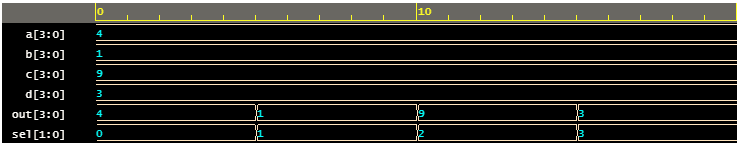
シミュレーションログ ncsim> run [0] sel=0x0 a=0x4 b=0x1 c=0x9 d=0x3 out=0x4 [5] sel=0x1 a=0x4 b=0x1 c=0x9 d=0x3 out=0x1 [10] sel=0x2 a=0x4 b=0x1 c=0x9 d=0x3 out=0x9 [15] sel=0x3 a=0x4 b=0x1 c=0x9 d=0x3 out=0x3 Simulation complete via $finish(1) at time 20 NS + 0
Verilog