


Spectrino:TinyML Arduino&IoTベースのタッチフリーソリューション
コンポーネントと消耗品
>  |
| × | 1 | |||
 |
| × | 1 | |||
| × | 1 | ||||
| × | 1 | ||||
 |
| × | 1 | |||
 |
| × | 2 | |||
| × | 1 | ||||
| × | 1 | ||||
 |
| × | 1 | |||
 |
| × | 1 | |||
 |
| × | 1 |
必要なツールとマシン
>  |
|
アプリとオンラインサービス
>  |
| |||
 |
| |||
 |
| |||
 |
|
このプロジェクトについて
概要
パンデミックは社会的相互作用に制約をもたらしました:距離。 このリスク要因を考慮すると、世界中の国々でさまざまなレベルの検疫が行われており、消費者数が大幅に減少したため、多くのモールが閉鎖されなければなりませんでした。 。これにより、非常に高いレベルのレイオフが発生しました。 モール職員の 、および同様の事業主にとっての経済的課題 。
これにより、2020年7月2日の時点で、COVID-19により、米国では比較的低所得(年収40,000ドル未満)の失業率が発生しています。宿泊施設と外食産業、および小売業と娯楽は、合計で、失われた推定雇用の約4,000,000を数えます。
食品、消費者、小売業が解雇された従業員の数が最も多い上位6業界に登場する、さまざまな業界が直面する経済的課題(推定20,000人以上の雇用に相当)。この調査で考慮された米国以外のすべての地域に「国際的」を含めると仮定すると、世界全体のレイオフ数は推定103,000人以上に達します。
<図>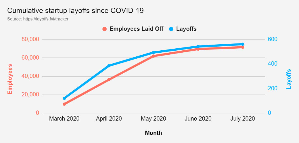
合併症
与えられたデータを考慮して、チームは、まだ開いているモールについて、さまざまな店舗の人口密度に関してリスクの不確実性があるという大きな課題を決定しました。これとは別に、フェイスマスクを着用し、タッチを避けることが多くの場所で義務付けられていますが、それでも違反があります。これにより、リモートで作業する余裕がないモールの担当者やビジネスオーナーが、この新しい通常のワークスペースを安全にナビゲートすることがより困難になります。これは疑問を投げかけます:どの時点でも、モール内の特定の店が安全に入ることができるという適切な確実性レベルをどのように保証できますか?
私たちは今、流行しているCOVID-19パンデミックと戦っています。また、現在、より安全な対策を講じて、一般的な状況に適応しなければならない状況にあります。ウイルス感染を防ぐためのより多くの安全対策で生活が正常に戻る一方で、公共の場所や混雑した地域での安全性の向上も都市で普及しています。しかし、私たちが安全対策を破り、貧しい人々に会うために危険な要素と相互作用しなければならない多くの状況がありました。ここでは、プロジェクトは、タッチの相互作用またはタッチによるCOVID-19の蔓延の防止に取り組んでいます。
タッチによるウイルスの拡散を確認するための実験が行われました。結果は次のように評価されました:
そのため、住宅や社会で最も一般的に使用されているデバイスを自動化して、デバイスとのハンズフリー通信を確保することにしました。
このプロトタイプを作成する際に、次のソリューションが開発されました
- Arduino33 BLE Senseに導入されたTinyMLを使用したスマートインターコムシステム: 以下は、コンピュータービジョンとTinyMLモデルを使用して、ドアの外にいる人を検出し、人がベルに触れずにベルを鳴らすタッチフリーソリューションです。
- IoTとアラートシステムを使用した温度監視システム: パンデミックの中で、安全性は重要な側面になっています。したがって、温度監視システムはIoT Thingspeakダッシュボードを利用して、入室中に人を検出し、温度を測定します。この温度は、タイムリーな傾向とデータ分析のためにIoTダッシュボードに表示されます。異常な温度が検出されると、アラートが生成され、その時点で人は2回目の検査を受けます。
- Arduino BLE33センスで音声認識TinyMLモデルを使用したタッチフリーエレベータシステム: 私たちは一日に数回、エレベーターを使って建物を上り下りしますが、通勤中の他の人が触れた汚染されたスイッチに触れることを常に恐れています。したがって、この音声認識モデルは、人がいつ上昇または下降したいかを識別し、同様にアクションを実行します。
- TinyMLおよびIoT監視システムに基づくMaskModel検出システム: この方法では、Arduino BLE 33センスにデプロイされたコンピュータービジョンモデルを使用して、人がマスクを着用しているかどうかを検出します。同様に、このデータはIoTダッシュボードに送信され、危険な時間に応じて監視および制限を課します。
- TinyML、IoT、コンピュータービジョンを使用した、スーパーマーケットやモールでのスマートキューの監視とシステムの確立: このモデルは、スーパーマーケットの外に立っている人を検出し、一度に50人がスーパーマーケットに入ることができるようにします。内部の人々が買い物を完了し、次の50人のセットが再びモールに入るのを許可するためにさらに15分待ちます。これは、Arduino 33BLEセンスにデプロイされたコンピュータービジョンとTinyMLを使用して行われます。このデータは、リアルタイムデータを追跡できるIoTダッシュボードに投影されます。
- モール内の通路の人員監視システムと汚染ベースの消毒システム :このソリューションは、モールまたはスーパーマーケットのエリアに配置された人物検出アルゴリズムを使用し、エリアの人物汚染がしきい値を超えた場合、UV光でそのエリアを自己消毒します。消毒の期間と時間は、分析のためにスーパーマーケットのスタッフのためにIoTダッシュボードに予測されます。
設定(プロジェクトの要件):
必要なハードウェア:
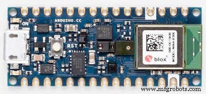
1)Arduino33BLEセンス
<図>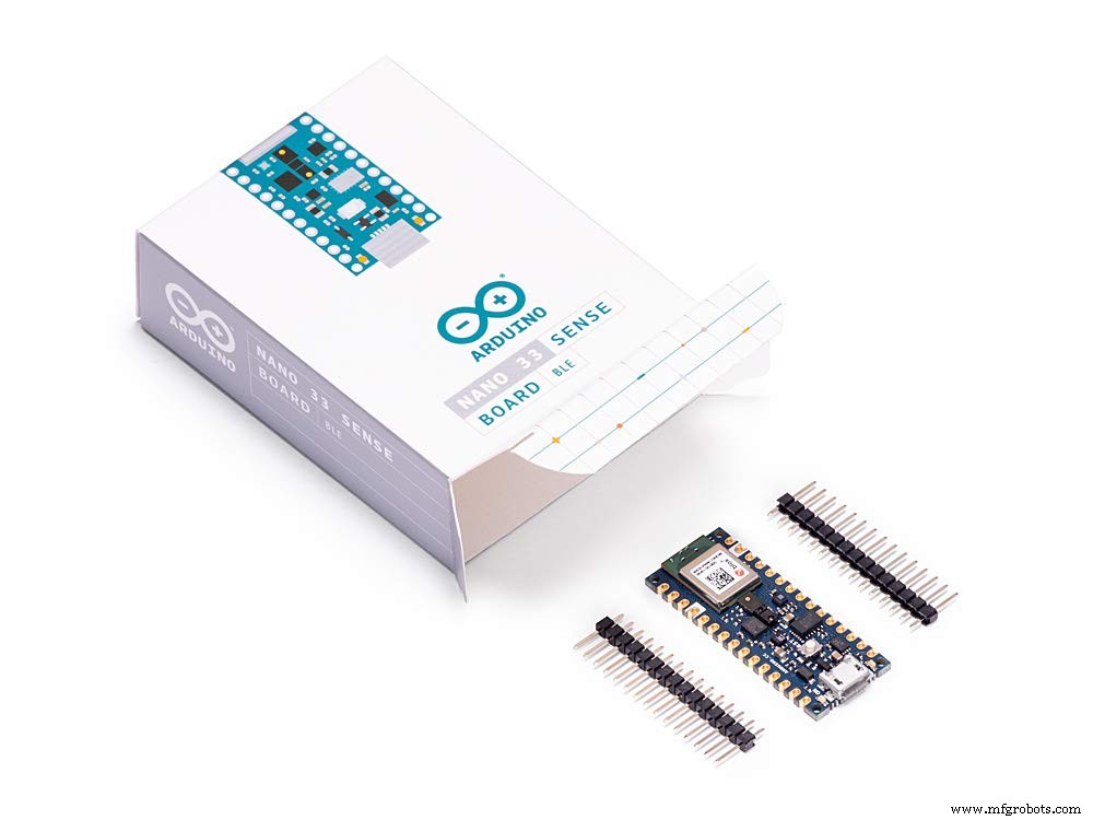
Arduino Nano 33 BLE Senseは、従来のArduino Nanoを進化させたものですが、はるかに強力なプロセッサであるNordic SemiconductorsのnRF52840、64MHzで動作する32ビットARM®Cortex™-M4CPUを備えています。これにより、Arduino Uno(1MBのプログラムメモリ、32倍の大きさ)よりも大きなプログラムを作成でき、さらに多くの変数(RAMは128倍の大きさ)を使用できます。メインプロセッサには、NFCを介したBluetooth®ペアリングや超低消費電力モードなど、その他のすばらしい機能が含まれています。
埋め込まれた人工知能
このボードの主な機能は、センサーの印象的な選択に加えて、TinyMLを使用してエッジコンピューティングアプリケーション(AI)を実行できることです。 TensorFlow™Liteを使用して機械学習モデルを作成し、ArduinoIDEを使用してボードにアップロードできます。
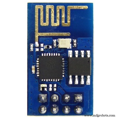
2)ESP8266 ESP-01
<図>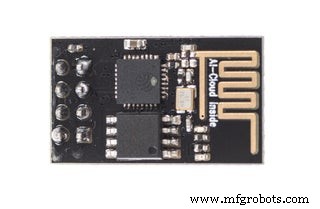
ESP8266 ESP-01 マイクロコントローラーを可能にするWi-Fiモジュールです Wi-Fiネットワークへのアクセス 。このモジュールは自己完結型の SOC (System On a Chip)これは、 Arduino で通常行うように、入力と出力を操作するためにマイクロコントローラーを必ずしも必要としません。 たとえば、ESP-01は小さなコンピュータとして機能するためです。 ESP8266のバージョンに応じて、最大9つのGPIO(汎用入出力)を持つことができます。したがって、Wi-FiシールドがArduinoに行うようにマイクロコントローラーにインターネットアクセスを与えることができます。または、Wi-Fiネットワークにアクセスできるだけでなく、マイクロコントローラーとしても機能するようにESP8266をプログラムするだけです。これにより、ESP8266は非常に用途が広くなります。
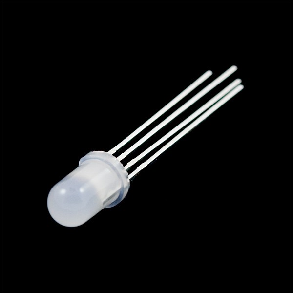
3)Arducam Mini 2MP plus
<図>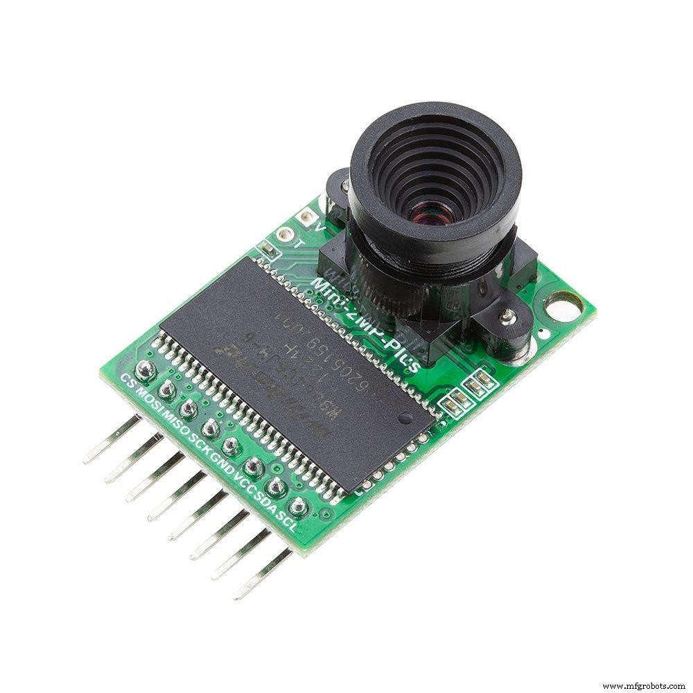
ArduCAM-2MP-Plusは、ArduCAMシールドRev.Cの最適化バージョンであり、高解像度2MP SPIカメラであり、カメラ制御インターフェースの複雑さを軽減します。 2MP CMOSイメージセンサーOV2640を統合し、小型サイズに加えて、使いやすいハードウェアインターフェイスとオープンソースコードライブラリを提供します。
ArduCAM miniは、SPIおよびI2Cインターフェースを備え、標準のArduinoボードとうまく結合できる限り、Arduino、Raspberry Pi、Maple、Chipkit、Beagleboneblackなどのあらゆるプラットフォームで使用できます。 ArduCAM miniは、一部の低コストのマイクロコントローラーにはないカメラインターフェースを追加する機能を提供するだけでなく、単一のマイクロコントローラーに複数のカメラを追加する機能も提供します。
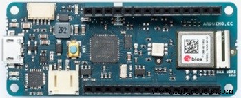
4)Arduino MKR WiFi 1010:
<図>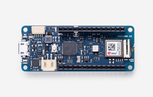
Arduino MKR WiFi 1010は、基本的なIoTおよびピコネットワークアプリケーション設計への最も簡単な入り口です。オフィスやホームルーターに接続されたセンサーネットワークの構築を検討している場合でも、携帯電話にデータを送信するBLEデバイスを作成する場合でも、MKR WiFi1010は多くの基本的なIoTアプリケーションのワンストップソリューションです。シナリオ。
ボードのメインプロセッサは、Arduino MKRファミリの他のボードと同様に、低電力のArm®Cortex®-M032ビットSAMD21です。 WiFiおよびBluetooth®接続は、u-bloxのモジュールであるNINA-W10、2.4GHz範囲で動作する低電力チップセットを使用して実行されます。さらに、Microchip®ECC508暗号チップを介して安全な通信が保証されます。それに加えて、バッテリー充電器と方向付け可能なRGBLEDが搭載されています。
ソフトウェアツール:
1)ArduinoWebエディター
<図>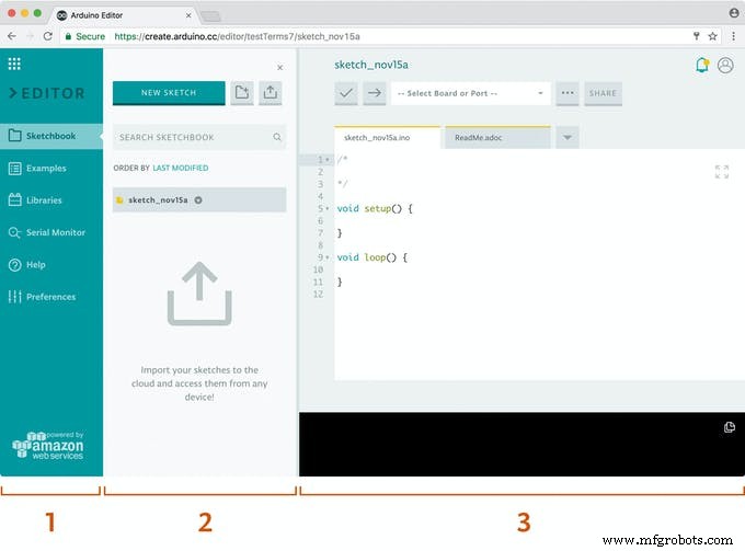
Arduino Createは、メーカーとプロの開発者がコードを記述し、コンテンツにアクセスし、ボードを構成し、プロジェクトを共有できるようにする統合オンラインプラットフォームです。アイデアから完成したIoTプロジェクトにこれまでになく迅速に移行します。 Arduino Createを使用すると、オンラインIDEを使用したり、複数のデバイスをArduino IoT Cloudに接続したり、Arduino Project Hubでプロジェクトのコレクションを参照したり、Arduino DeviceManagerを使用してボードにリモート接続したりできます。また、ステップバイステップのガイド、回路図、リファレンスとともに、自分の作品を共有したり、他の人からフィードバックを受け取ったりすることができます。
2)Edge Impulse Studio:
<図>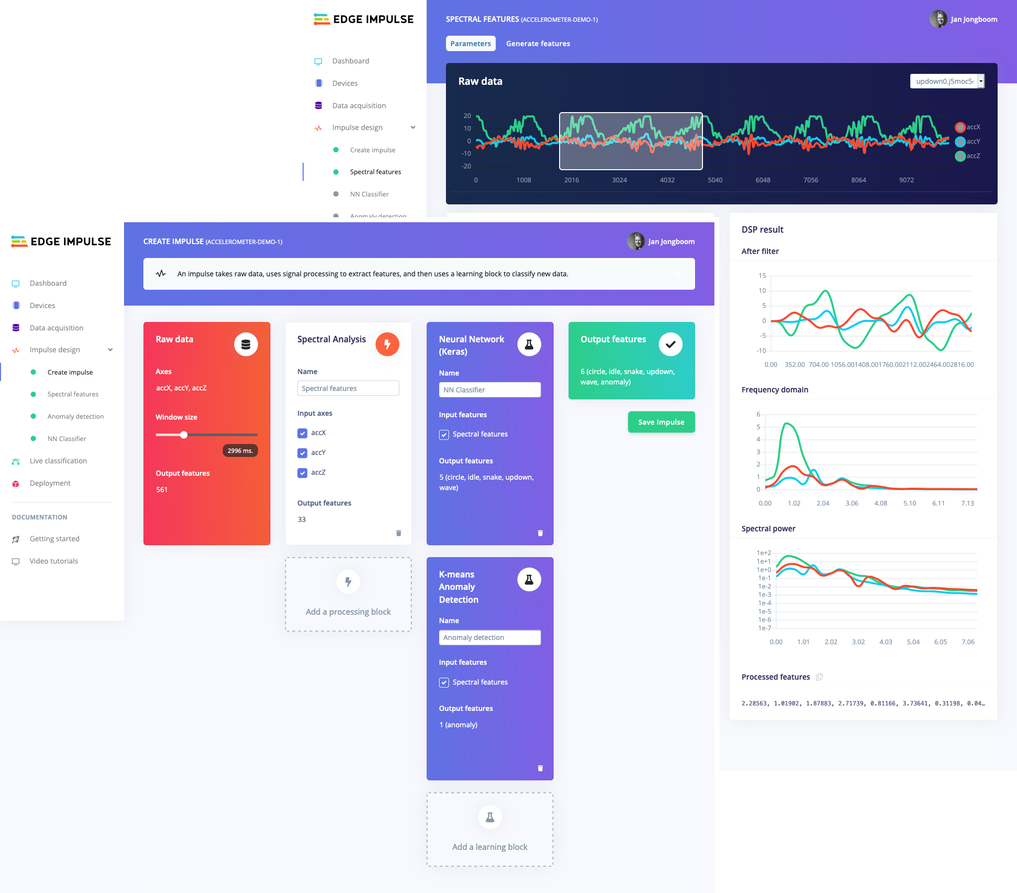
マイクロコントローラーでMLを実行する傾向は、EmbeddedMLまたはTinyMLと呼ばれることもあります。 TinyMLは、クラウドにデータを送信することなくスマートな意思決定を行うことができる小さなデバイスを作成する可能性があります。これは、効率とプライバシーの観点から優れています。 (人工ニューラルネットワークに基づく)強力な深層学習モデルでさえ、現在マイクロコントローラーに到達しています。過去1年間で、マイクロコントローラー用のTensorFlow Lite、uTensor、ArmのCMSIS-NNなどのプロジェクトを通じて、ディープラーニングモデルをより小さく、より速く、組み込みハードウェア上で実行できるようにすることに大きな進歩がありました。ただし、高品質のデータセットの構築、適切な機能の抽出、これらのモデルのトレーニングと展開は、依然として複雑になる可能性があります。
Edge Impulseを使用すると、実際のセンサーデータをすばやく収集し、クラウドでこのデータを使用してMLモデルをトレーニングし、モデルをArduinoデバイスにデプロイできるようになりました。そこから、1回の関数呼び出しでモデルをArduinoスケッチに統合できます。そうすれば、センサーは非常にスマートになり、現実世界の複雑なイベントを理解できるようになります。組み込みの例では、加速度計とマイクからデータを収集できますが、他のセンサーを数行のコードで簡単に統合できます。
3)Thingspeak:
<図>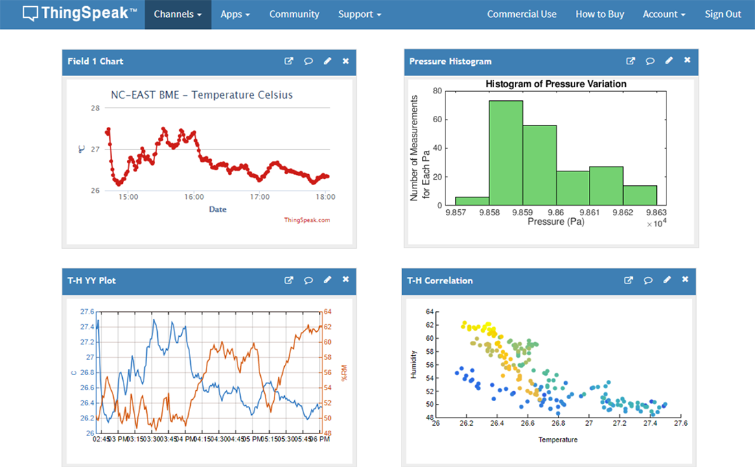
ThingSpeak™は、クラウド内のライブデータストリームを集約、視覚化、分析できるIoT分析サービスです。 ThingSpeakは、デバイスからThingSpeakに投稿されたデータを即座に視覚化します。 ThingSpeakでMATLAB®コードを実行する機能により、オンライン分析を実行し、データが入ってくるときにデータを処理できます。ThingSpeakは、分析を必要とするプロトタイピングおよび概念実証IoTシステムによく使用されます。
Rest APIまたはMQTTを使用して、インターネットに接続された任意のデバイスからThingSpeakに直接データを送信できます。さらに、Things Network、Senet、Libelium Meshliumゲートウェイ、Particle.ioとのクラウド間の統合により、センサーデータがLoRaWAN®および4G / 3Gセルラー接続を介してThingSpeakに到達できるようになります。
実装の開始:
最初のプロジェクト:Arduino BLE 33センスで音声認識TinyMLモデルを使用したタッチフリーエレベータシステム:
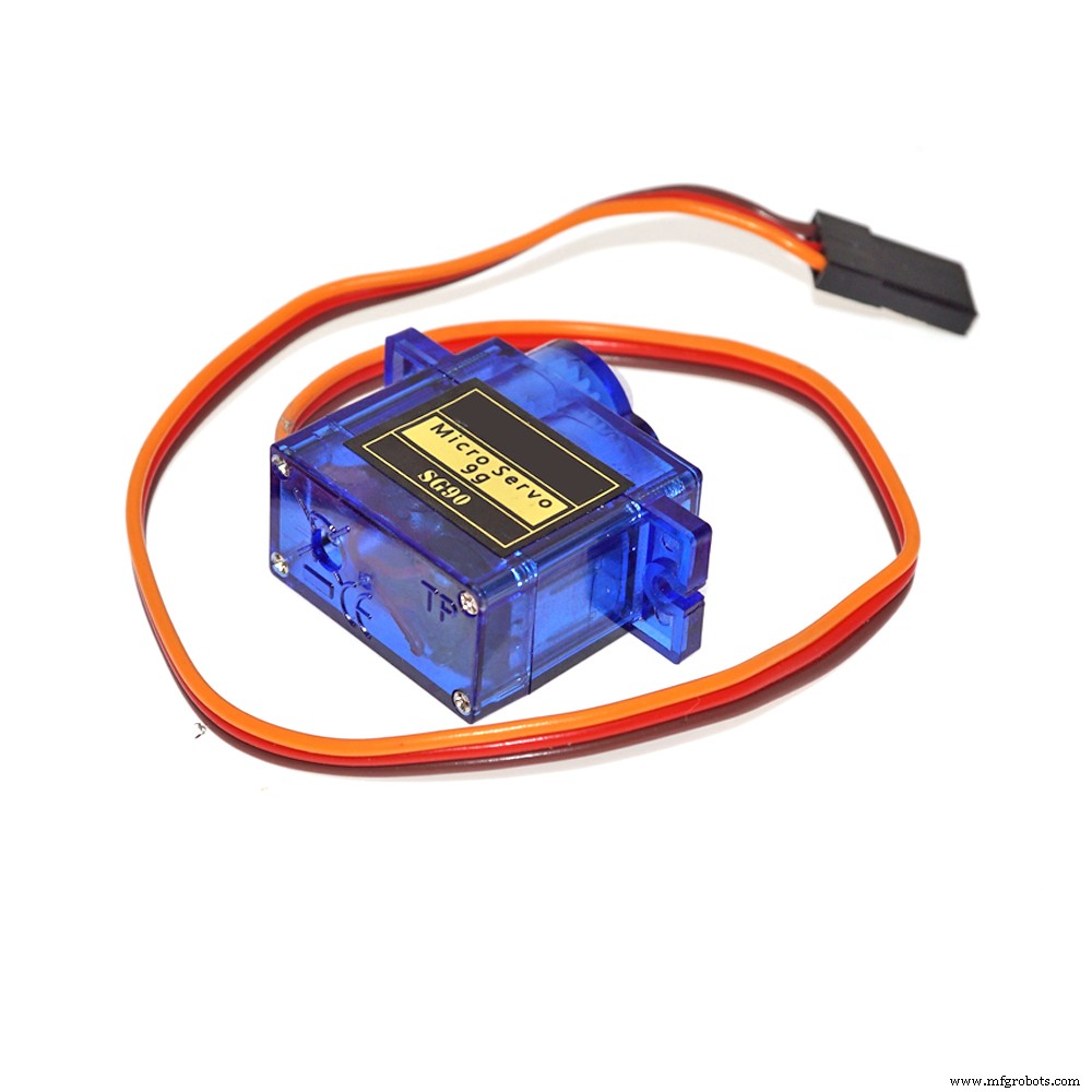
通勤中は1日に数回エレベーターを利用しています!一般的に使用されるスイッチは、以前にリフトに触れたことがあるすべての人によって汚染されています。そこで、音声コマンドを使用し、IoTやWifiネットワークを使用せずに、連携してアクションを実行する、エレベータ用のタッチフリーソリューションを作成することにしました。ジェスチャ制御または超音波センサーを使用して操作を実行するタッチフリーエレベータシステムのソリューションが実装されていますが、これらのセンサーが直面する問題は、より近い距離から起動する必要があるため、タッチのリスクが高くなることです。また、これらのセンサーは感度が高く、小さな物体が邪魔になって作動しても作動します。したがって、私はArduino 33BLEセンスの音声検出を使用してより正確なソリューションを作成することを提案しました。このモデルは、 "up" の2つのコマンドを取ります または "down" それに応じて、スイッチのそれぞれのボタンを押すためにサーボにデータを送信します。スイッチをアクティブにするためにサーボにデータを送信するという考えは、大多数の社会がスイッチとディスプレイシステムを事前に構築しており、したがってこれらの既存のシステムを妨げないため、これは機能を制御するための外部ハードウェアシステムを追加するために作成されます。
この機能を実行するために使用されるコアロジックは次のとおりです。
<図>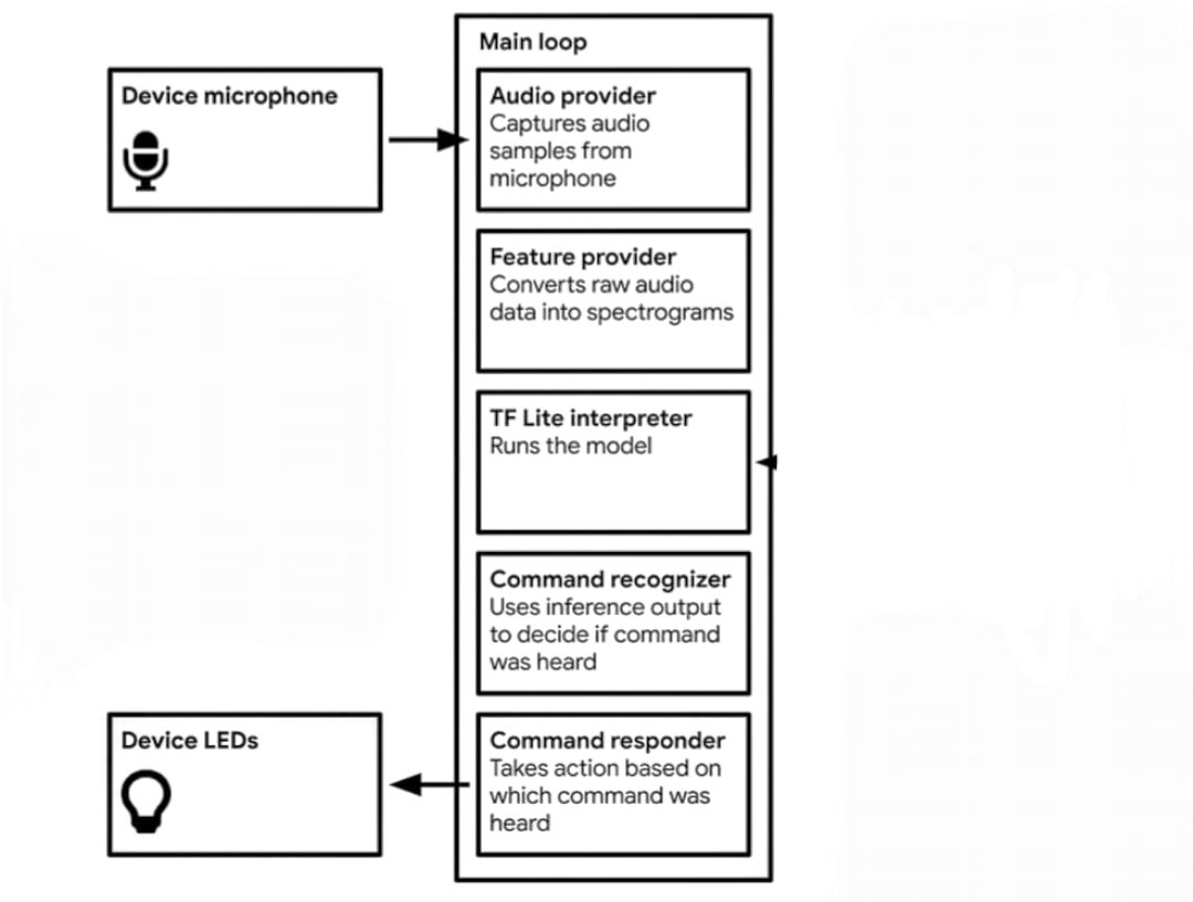
Edge ImpulseStudioで「up」コマンドと「Speech」コマンドを解釈するようにモデルをトレーニングする
a)トレーニングおよびテストデータセットを使用した生データの蓄積。ここでは、「上」と「下」の各データ期間が2秒で、1:30分のデータを蓄積しました。
<図>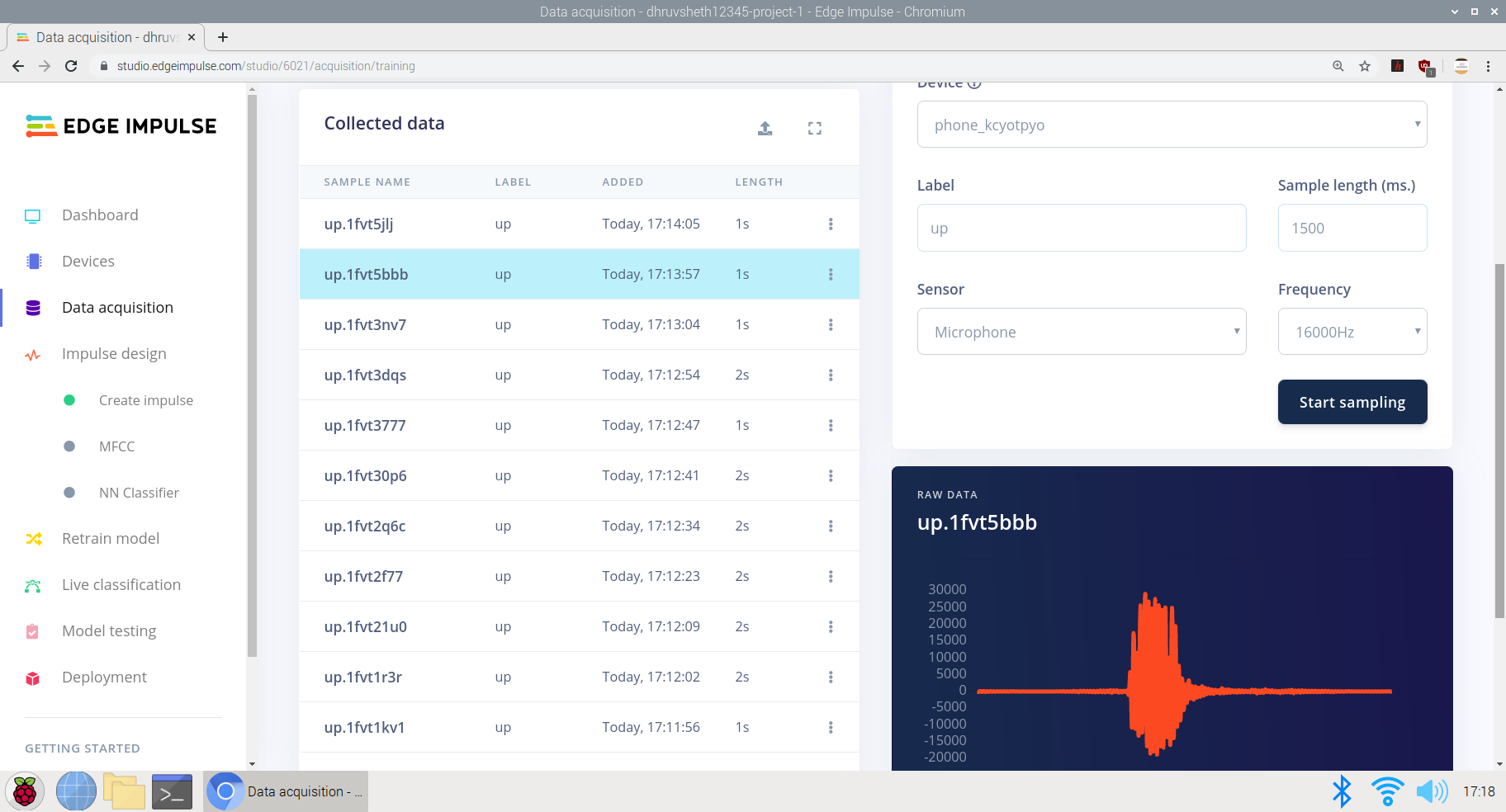
b)必要なパラメータに基づいてインパルスを作成する:
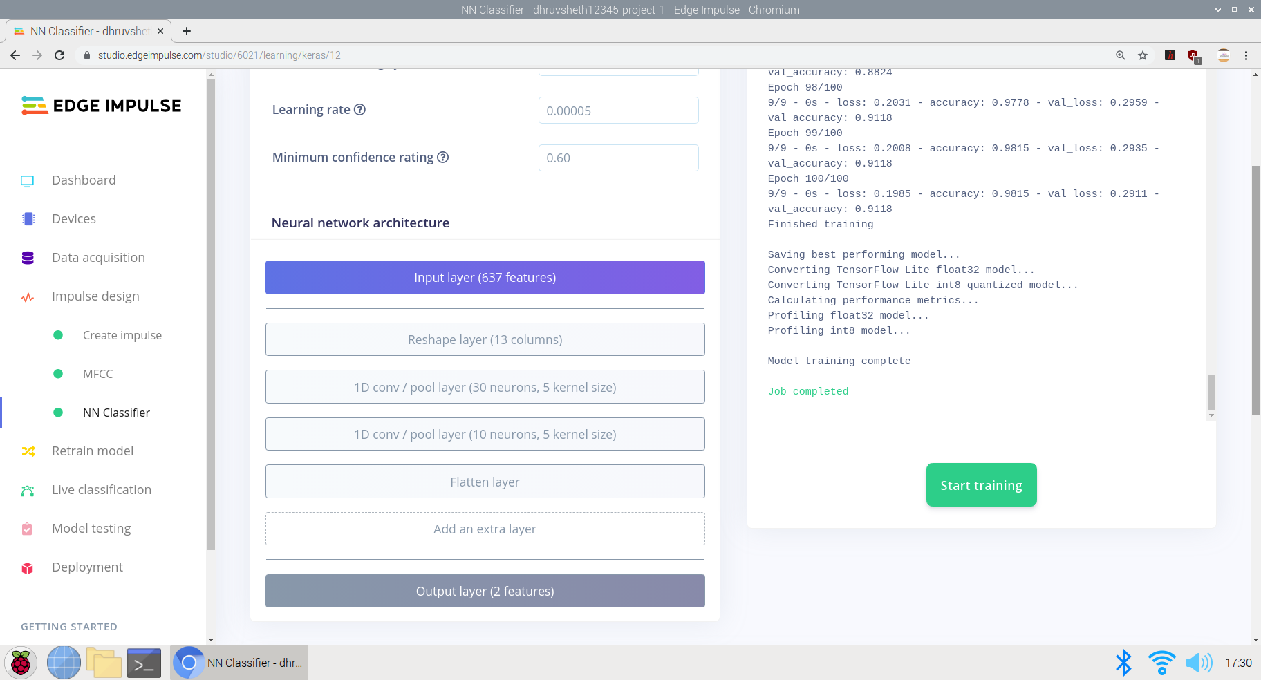
ここでは、ウィンドウの増分サイズを300msに設定し、マイクと加速度計のデータ専用のKeras NeuralNetworkに基づいてトレーニングを行いました。
<図>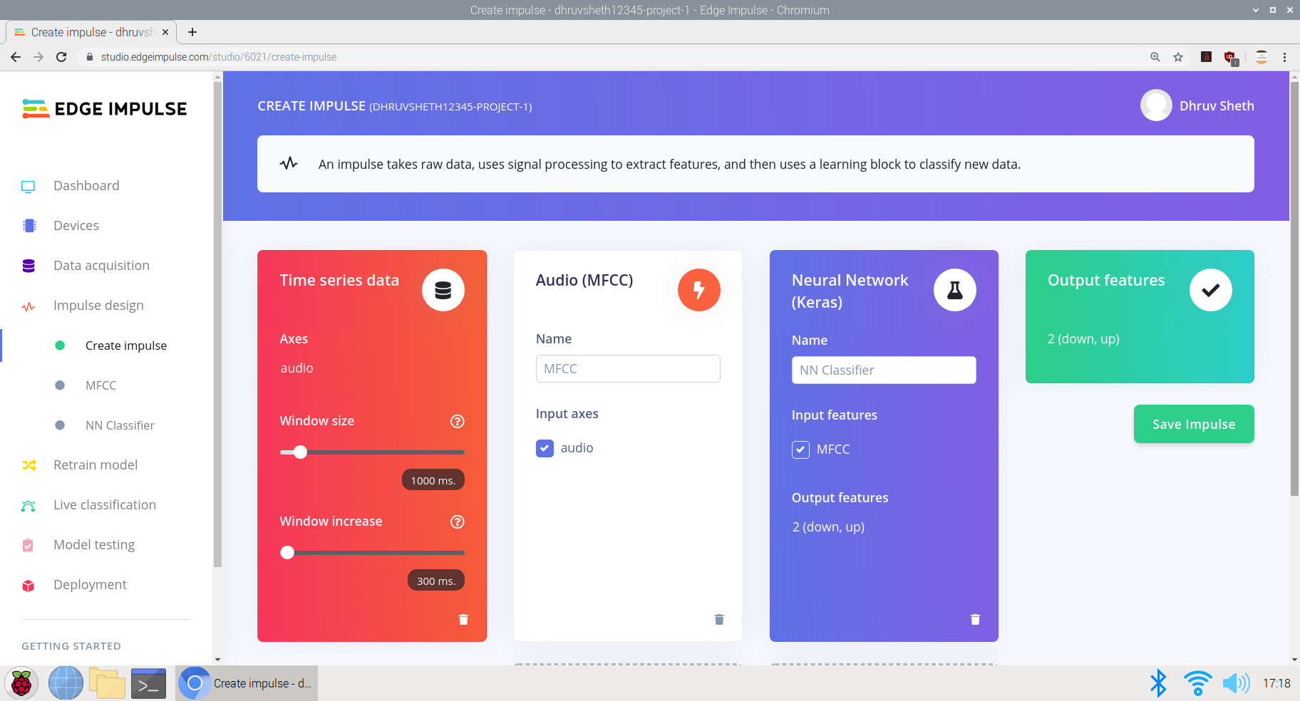
c)生データから処理済みデータへの変換。生データのすぐ下に生データの特徴が表示され、処理されたデータはケプストラム係数に基づくDSP結果として表示されます。
<図>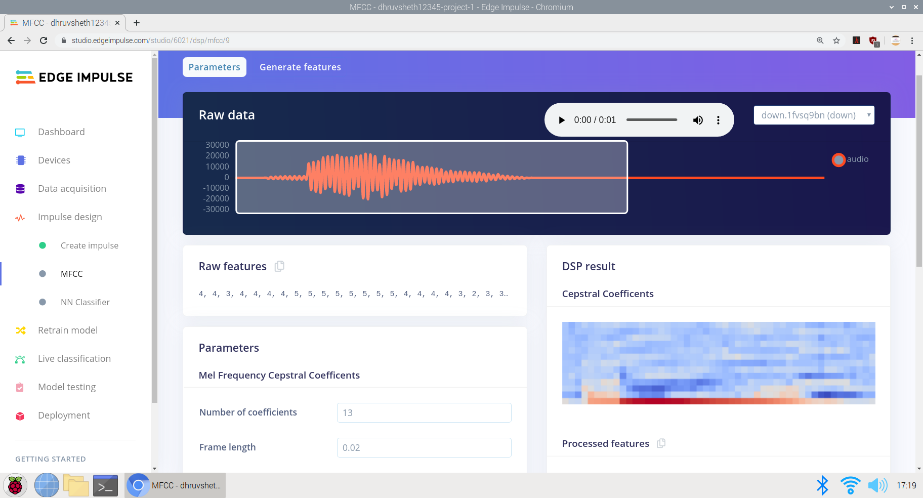 <図>
<図> 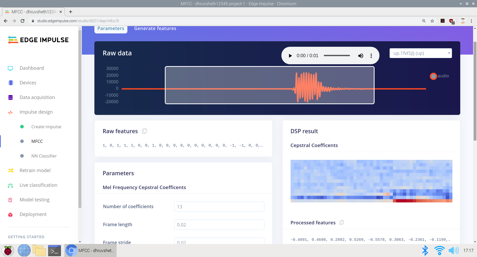
d)処理された特徴を生成するための入力データのトレーニング。同じデータに基づいて低周波数と高周波数のデータを記録し、インパルスをより適切にトレーニングし、すべてのタイプの音声に基づいて音声認識を正確にトレーニングできるようにしました。ここでは、x、y、z軸を中心に微分された「S」カーブでフィーチャ出力を取得しています。
<図>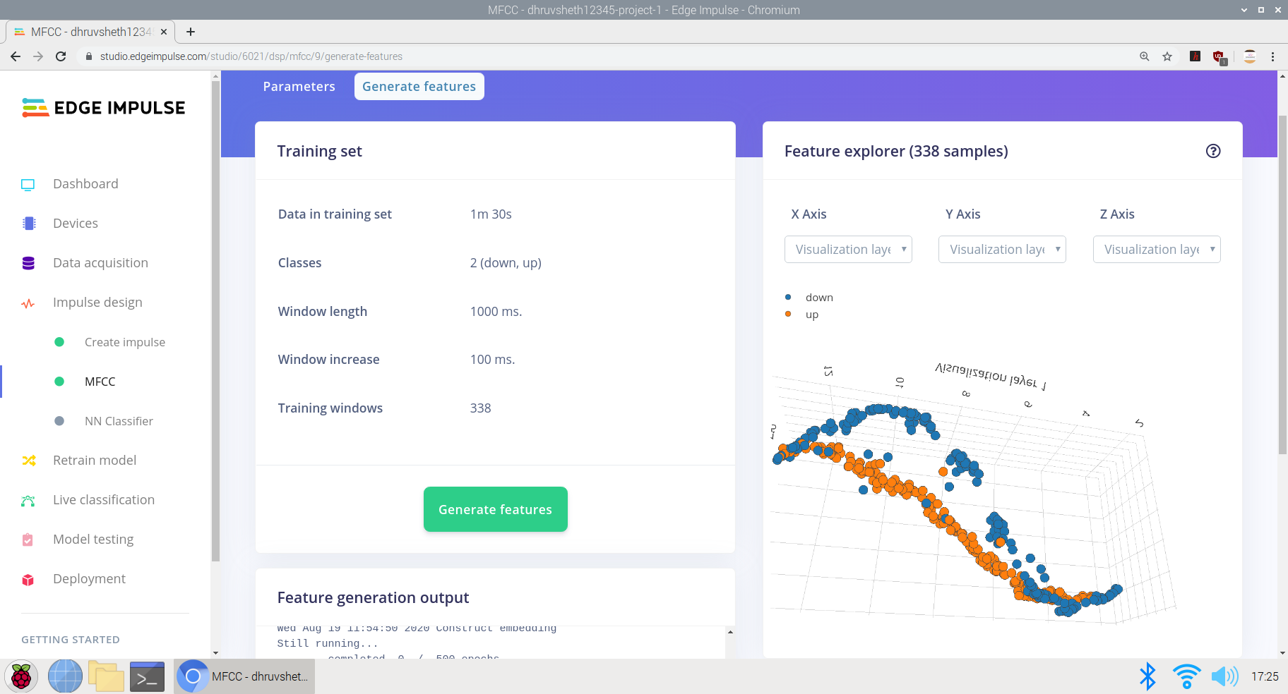 <図>
<図> 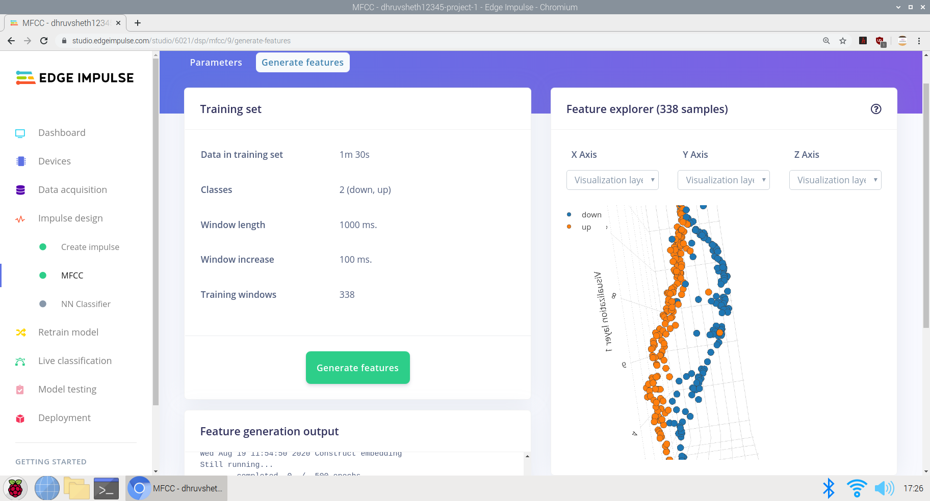 <図>
<図> 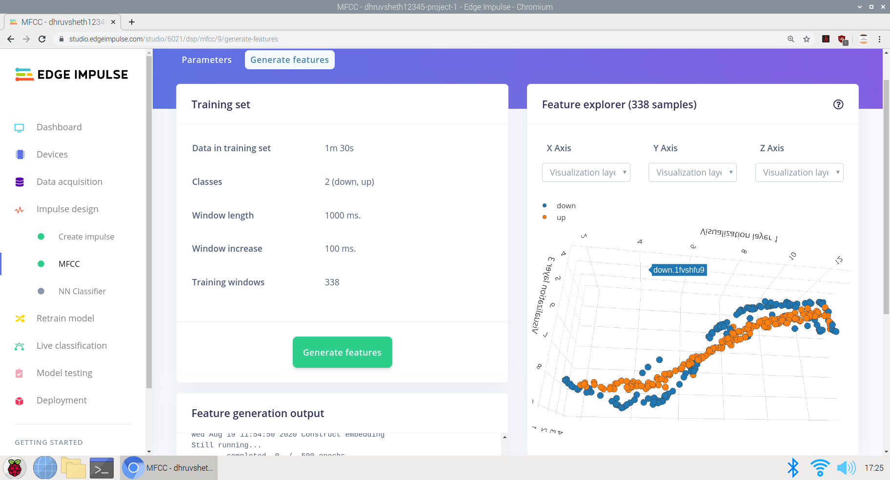
e)最後に、エッジインパルスニューラルネットワーク分類器でニューラルネットワークアーキテクチャを設計し、ネットワークをトレーニングします。
ここで、データ入力用に設計されたニューラルネットワークアーキテクチャは次のとおりです。
- 入力レイヤー
- レイヤーの形状を変更する
- 1Dコンボプールレイヤー(30ニューロン、5カーネル)
- 1Dコンボプールレイヤー(10ニューロン、5カーネル)
- フラットレイヤー
モデルは、91.2%の平均精度と0.29の損失で、かなり良好に機能しました。モデルは100トレーニングサイクル(エポック)でトレーニングされました。混同行列は非常に明確で正確に見え、残りのデータのほとんどはそれぞれのラベル付けされたクラスに一致します。
<図>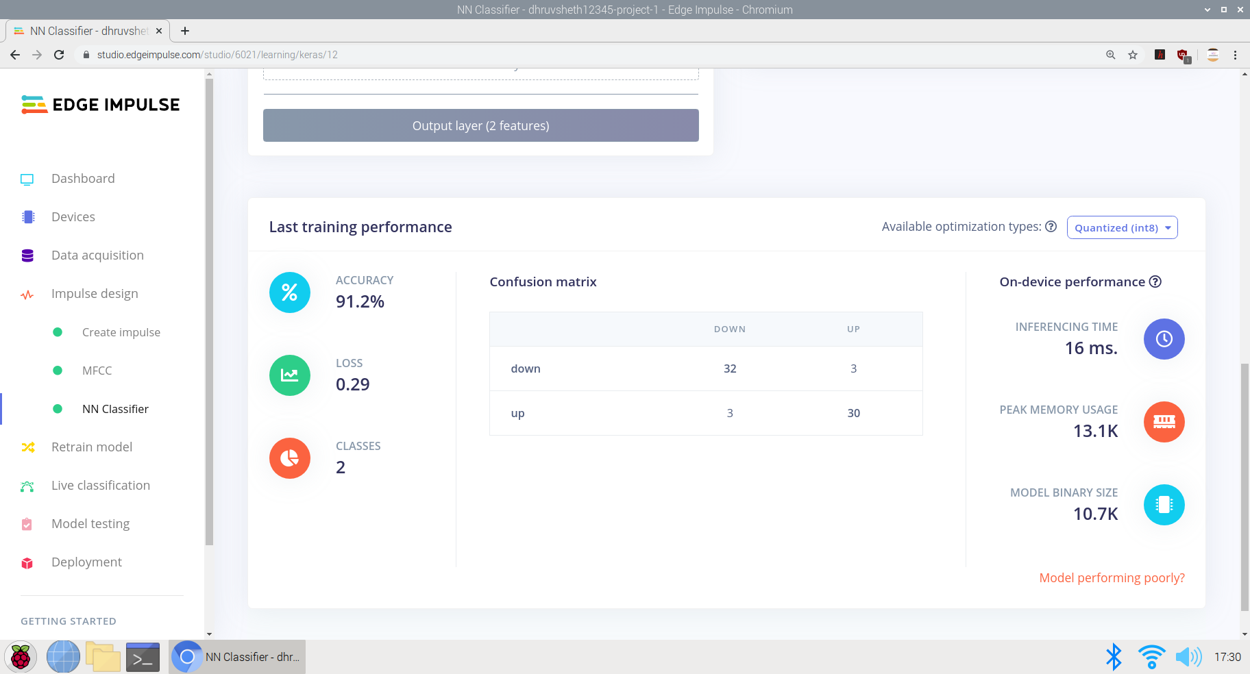
モデルがトレーニングされた後、テストデータとライブデータを使用してモデルをテストしました。モデルは、24秒のテストデータに基づいて75%の精度を取得しました
<図>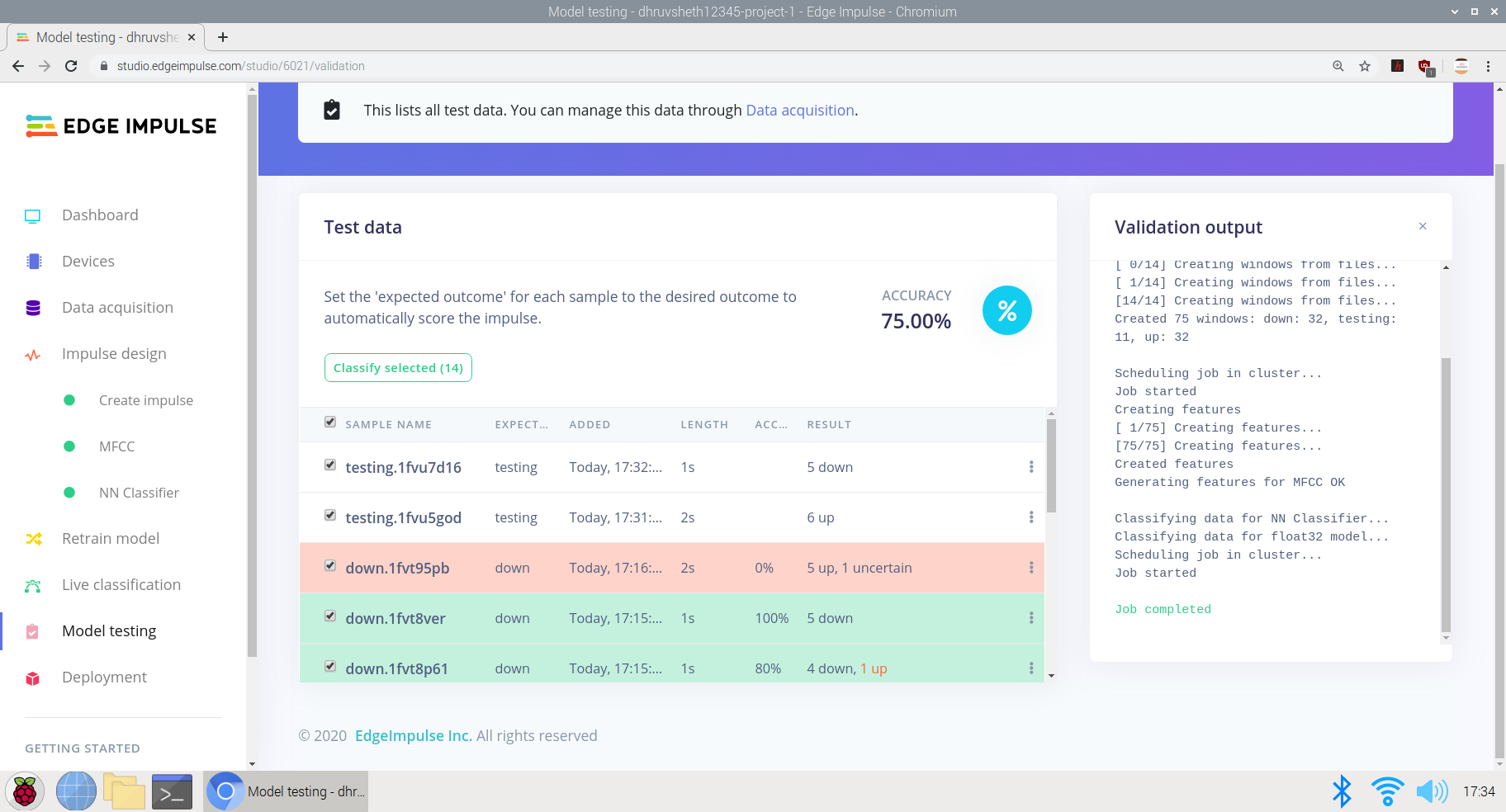 <図>
<図>  <図>
<図> 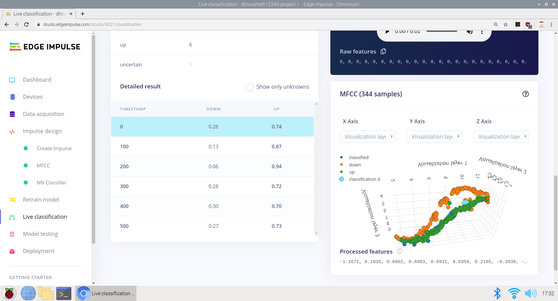
最後に、モデルがトレーニングされ、ロジックで適切な精度が得られた後、モデルをArduinoライブラリとしてデプロイし、Arduino 33BLEセンスにデプロイしました。
<図>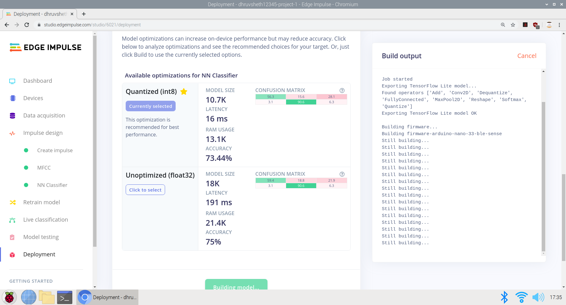
スクリプトの準備ができたら、カスタマイズを容易にするためにArduino Web Editorで編集を開始し、Arduino 33 BLESenseにデプロイできる最終的なスクリプト出力は次のとおりです。
Arduino WebEditorプラットフォームのmain.inoファイルは次の場所にあります:
Main-script.ino-ArduinoWebエディター
Main-script.ino-Github
Arduino 33 BLESenseへの導入
この記事の執筆時点では、マイクを内蔵したArduinoボードはArduino Nano 33 BLE Senseのみであるため、このセクションではこれを使用します。別のArduinoボードを使用していて、独自のマイクを接続している場合は、実装する必要があります
この記事の執筆時点では、マイクを内蔵したArduinoボードはArduino Nano 33 BLE Senseのみであるため、このセクションで使用します。
Arduino Nano 33 BLE SenseにはLEDも組み込まれています。これは、単語が認識されたことを示し、サーボを制御して機能を実行するために使用します。
<図>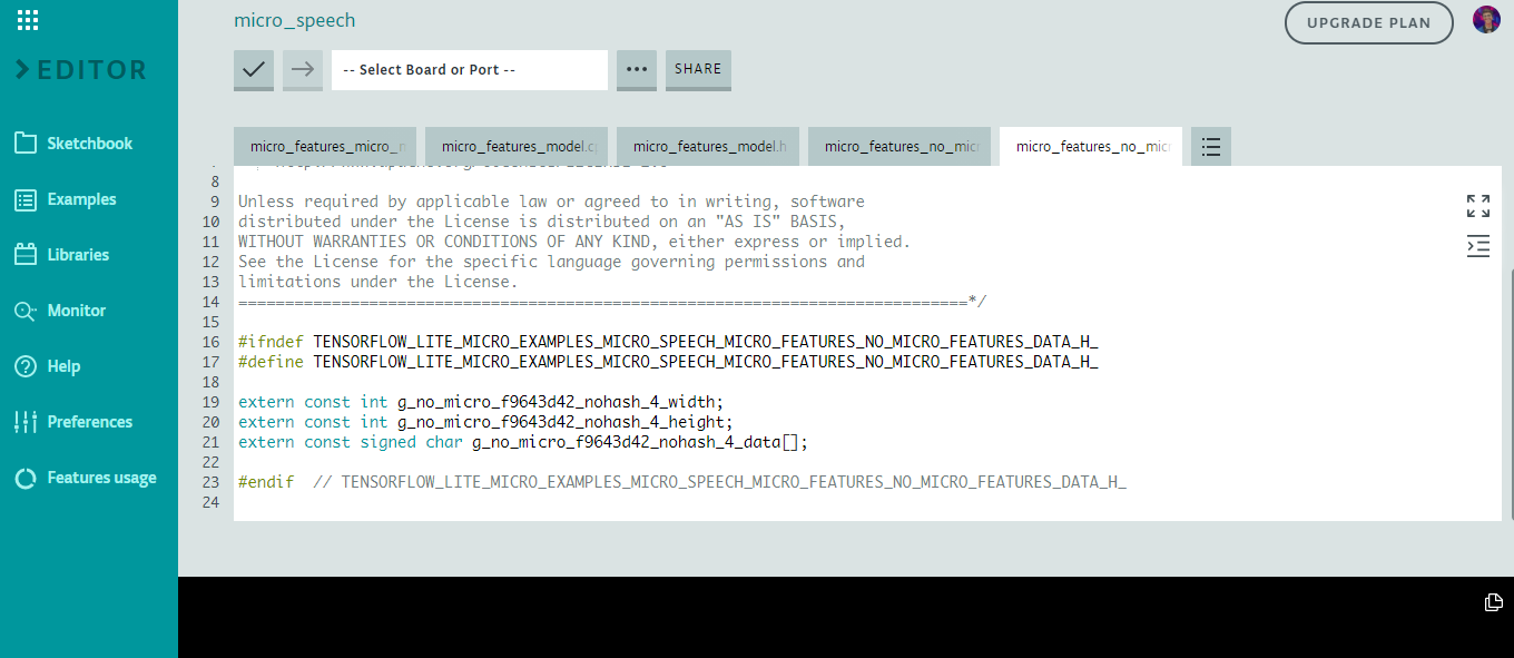
これがモデルのマイクロ機能コードのスニペットです
コマンドへの応答のロジックは次のように機能します:
  //コマンドが聞こえたら、適切なLEDを点灯し、適切なサーボをオンにします
 if(found_command [0] =='up'){
 last_command_time =current_time;
 digitalWrite(LEDG、LOW); //緑色でアップ、LOWコマンドでLEDをオンにします
 servo_7.write(0); //サーボを0度に回転させて、「上へ」と言われたときにリフトのボタンをクリックします
 delay(100);
 digitalWrite(LEDG、HIGH); //コマンドを点滅させた後にLEDをオフにします
 servo_7.write(180); //サーボが元の位置(180度)に戻る
}
 //コマンドが聞こえたら、適切なLEDを点灯し、適切なサーボをオンにします
 if(found_command [0] =='down'){
 last_command_time =current_time;
 digitalWrite(LEDG、LOW); //緑色でアップ、LOWコマンドでLEDをオンにします
 servo_7.write(0); //サーボを0度回転させて、「下」と言ったときにリフトのボタンをクリックします
 delay(100);
 digitalWrite(LEDG、HIGH); //コマンドを点滅させた後にLEDをオフにします
 servo_7.write(180); //サーボが元の位置(180度)に戻る
}
2番目のコマンド応答は上記と同じですが、コマンド「ダウン」が聞こえるとサーボが回転します。
データをトレーニングした後、次のようにトレーニングされたtfliteデータセットの出力を取得します。
ここでは、Arduino Nano 33 BLE Senseに内蔵マイクを使用しており、モデルはArduino Nanoボードの256kbフラッシュメモリから平均約24〜28Kbを使用しています。このモデルは、画像認識モデルと比較して比較的軽量であり、はるかに高速で情報を処理できます。
音声認識モデルのロジックは次のようになります。
-
データがキャプチャされます -
マイクからオーディオサンプルをキャプチャする -
生のオーディオデータをスペクトログラムに変換します -
Tfliteインタープリターがモデルを実行します -
推論出力を使用してコマンドが聞こえたかどうかを判断します -
ダウンコマンドが聞こえた場合、サーボはリフトコントロールパネルのダウンキーを押して移動します。 -
upコマンドが聞こえた場合、サーボはリフトコントロールパネルの上方キーを押して移動します。
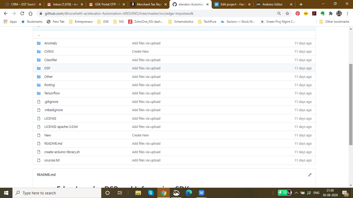
<コード> 上記は、トレーニングされたモデルのライブラリ内のデータです。主な機能はTensorflowファイルに含まれています。
プロジェクトの回路図:
<図>
Arduino Nano 33 BLE Senseは、生データを収集するための内蔵マイクを利用しています。 Arduinoでの推論には時間がかかるため、データを正確に処理するために100ミリ秒の遅延を追加しました。したがって、2つの録音サンプル間で、内蔵の青いLEDが点滅し、2つのLEDフラッシュ間で聞こえる/言われる応答を示します。
<図>
これは、Arduino 33 BLE Senseのシミュレーションであり、2つの成功したマイク入力間隔の間でLEDが点滅することを示しています
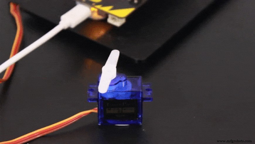
コマンド入力に基づいて、サーボはそれに応じて回転します
超音波センサーやジェスチャーセンサーを使用するなど、タッチフリーのエレベーター自動化システムに代わるものは他にもありますが、どちらにも独自の欠陥があるため、音声制御のエレベーター自動化システムを作成することにしました
超音波センサーが直面する欠陥: 超音波センサーは非常に動きに敏感です。通路内を移動する物体が超音波センサーの範囲内に入ると、これらがアクティブになります。超音波センサーも十分に正確ではなく、これらは間違った情報を処理することがあります。
ジェスチャー制御センサーの欠陥: これらのセンサーは超音波センサーよりも正確ですが、より近い距離からアクティブにする必要があります。これにより、手とリフトパネルが接触するリスクが高まります。
ただし、音声制御のエレベータパネルは、上記の2つのソリューションよりも正確であり、超音波およびジェスチャセンサーよりも遠くから起動できます。
<図>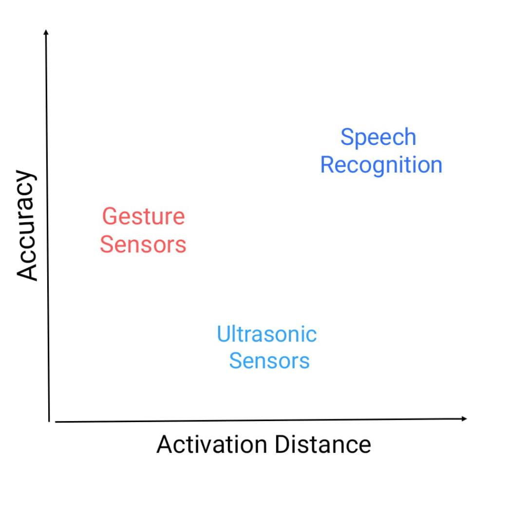
これは、精度と起動距離のグラフであり、これらのセンサーが立っている場所です。
<図>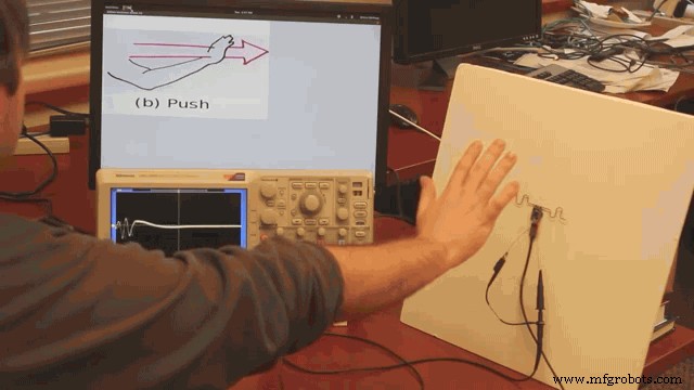
これは、ジェスチャセンサーをアクティブにするために必要な距離を示しています。この距離は本当に短いように見えるので、汚染率は高いです
次に、メインプロジェクトの2番目のサブプロジェクト部分に進みます
2番目のプロジェクト:顔認識とTinyMLを使用したスマートインターコムシステム:
CDCはサイトを更新し、新しいコロナウイルスに汚染された表面からの間接的な接触(フォマイト感染として知られている)が新しいコロナウイルスに感染する可能性があると述べたニュースリリースを発行しました。
研究によると、新しいコロナウイルスは、プラスチックや金属の表面、および段ボール上で最大3日間24時間持続する可能性があります。しかし、汚染された表面に触れることからCovid-19に感染するために、人が起こらなければならないことがたくさんあります。
まず、実際に感染を引き起こすのに十分な量のウイルスに接触する必要があります。たとえば、インフルエンザウイルスに感染するには、数百万のウイルスのコピーが表面から人の顔に到達する必要がありますが、ウイルスが直接肺に侵入する場合は数千のコピーしか必要ありません。ニューヨークタイムズ レポート。
人がたまたまウイルスの痕跡が多い表面に触れた場合、十分な量のウイルスを拾い上げてから、目、鼻、または口に触れる必要があります。そのため、公衆衛生の専門家は、触れないようにすることが非常に重要であると述べています。表面が頻繁になりすぎて、汚染されたオブジェクトや頻繁に触れられるオブジェクトに触れないようにします。
COVID-19ウイルスは世界中に広がっています。それがようやく治まったとしても、人々は人前で物に触れることに敏感になるでしょう。ほとんどのインターコムは、電話をかけるためにボタンを押す必要があるように設計されているため、人が何も触れる必要のないタッチレスインターコムソリューションが必要であると判断しました。
<図>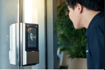
上の画像は、実装された顔認識ベースのインターホンシステムを示しています。
タッチベースのシステムの問題を解決するには、接触とタッチの場所を減らす必要があります。従来のインターホンシステムでは、押すとベルが鳴るスイッチベースのシステムで構成されています。表面の汚染のリスクを高めるタッチベースのシステムを刷新するために、tinyMLとTensorflow Liteに基づいて、Arduino 33 BLESenseにデプロイされたタッチフリーの顔認識システムを構築することにしました。
このスマートインターホンシステムでは、Arduino 33 BLE Senseに導入された人物検出アルゴリズムを使用しました。これにより、人物が識別され、LEDマトリックスディスプレイで「人物」と表示されてベルが鳴ります。
スマートインターホンシステムの実装に向けて:
このモデルの設計には、次のソフトウェアが使用されています。
- TensorFlow lite
- ArduinoWebエディター
で この人物検出モデルでは、プロジェクトに適した事前トレーニング済みのTensorFlow人物検出モデルを使用しました。この事前トレーニング済みモデルは3つのクラスで構成されており、そのうち3番目のクラスには未定義のデータセットが含まれています。
"unused"、
"person"、
"notperson"
私たちのモデルには、画像取り込みを実行するためのArducam Mini 2mp plusがあり、適切なfpsレートのこの画像データは、処理と分類のためにArduino Nano 33 BLESenseに送信されます。マイクロコントローラーは256kbのRAMを提供できるため、処理と分類のために各画像の画像サイズを標準の96 * 96に変更します。 Arduino Tensorflow Liteネットワークは、次のようなディープラーニングフレームワークで構成されています。
- 深さ方向のConv_2D
- Conv_2D
- AVERAGE Pool_2D
- フラットレイヤー
このディープラーニングフレームワークは、人物検出モデルのトレーニングに使用されます。
以下は、 Arduino_detetction_responder.cpp を介してマイクロコントローラーの出力を処理するときに定義される最も重要な関数です。
  //推論結果を処理します。
 uint8_t person_score =output-> data.uint8 [kPersonIndex];
 uint8_t no_person_score =output-> data.uint8 [kNotAPersonIndex];
 RespondToDetection(error_reporter、person_score、no_person_score);
次の関数定義では、 person_score 、 no_person_score データの分類率に基づいて定義されています。
ロジックは次のように機能します:
<コード>├──自律型インターコムシステム
├──ArducamMini2mpplus
│├──Arduinoに送信されるビジュアルデータ
├──Arduino33BLESense
│├ ──ifperson-score> no_person_score
││├──ブザーを鳴らす
││├──LEDマトリックスに「Person」を表示
││└──...繰り返すループ
付着 上記のロジックに基づいて、arducam Mini 2mp plusは視覚データを継続的に取り込み、このデータをArduino 33 BLE Senseに送信して、収集されたデータを処理および分類します。生データが処理済みデータに変換されると、トレーニングされたデータに従って分類されます。人が検出されると、Arduinoはブザーに信号を送信してアクティブにし、MAX7219は「人」を表示します。このようにして、システムのロジックが機能します。
コード内のロジックの機能と動作:
以下は、 main.ino に含まれているライブラリです。 モデルの機能のためのコード。
#include
#include "main_functions.h"
#include "detection_responder.h"
#include " image_provider.h "
#include" model_settings.h "
#include" person_detect_model_data.h "
#include" tensorflow / lite / micro / kernels / micro_ops.h "
# include "tensorflow / lite / micro / micro_error_reporter.h"
#include "tensorflow / lite / micro / micro_interpreter.h"
#include "tensorflow / lite / micro / micro_mutable_op_resolver.h"
#include "tensorflow / lite / schema / schema_generated.h"
#include "tensorflow / lite / version.h" 次のコードスニペットでは、ループが定義され、実行されています。これはmain.inoコードであるため、モデルのコア機能を制御します。これは、モデル内のライブラリを実行するために使用されます。
  void loop(){
 //プロバイダーから画像を取得します。
 if(kTfLiteOk!=GetImage(error_reporter、kNumCols、kNumRows、kNumChannels、
 input-> data。 uint8)){
 TF_LITE_REPORT_ERROR(error_reporter、 "画像キャプチャに失敗しました。");
}

 //この入力でモデルを実行し、成功することを確認します。
 if(kTfLiteOk!=インタプリタ-> Invoke()){
 TF_LITE_REPORT_ERROR(error_reporter、 "Invoke failed。");
}

 TfLiteTensor *出力=インタプリタ->出力(0);

 //推論結果を処理します。
 uint8_t person_score =output-> data.uint8 [kPersonIndex];
 uint8_t no_person_score =output-> data.uint8 [ kNotAPersonIndex];
 RespondToDetection(error_reporter、person_score、no_person_score);
}
次のコードスニペットには、キャプチャする画像を推測するために必要なライブラリが表示されています。キャプチャされた後の画像は、arduinoボードで解釈できる96 * 96の標準サイズに変換されます。
ここでは、Arducam mini 2mpOV2640ライブラリが利用されています。
このコードはarduino_image_provider.cppスニペットで提供されています
  #if defined(ARDUINO)&&!defined(ARDUINO_ARDUINO_NANO33BLE)
 #define ARDUINO_EXCLUDE_CODE
 #endif // defined(ARDUINO)&&!defined(ARDUINO_ARDUINO_NANO33BLE)

 #ifndef ARDUINO_EXCLUDE_CODE

 // Arducamライブラリで必要
 #include
 #include
 #include
 // Arducamライブラリ
 #include
 // JPEGDecoderライブラリ
 #include

 //チェックArducamライブラリが正しく構成されていること
 #if!(defined OV2640_MINI_2MP_PLUS)
 #error Arduino / libraries / ArduCAM / memorysaver.hでハードウェアプラットフォームとカメラモジュールを選択してください
 #endif

 // Arducamモジュールから受信したJPEGデータを保持するための一時バッファのサイズ
 #define MAX_JPEG_BYTES 4096
 //に接続されているピンArducamチップ選択
 #define CS 7

 //カメラライブラリインスタンス
 ArduCAM myCAM(OV2640、CS);
 // hol用の一時バッファカメラからのJPEGデータの処理
 uint8_t jpeg_buffer [MAX_JPEG_BYTES] ={0};
 //現在バッファにあるJPEGデータの長さ
 uint32_t jpeg_length =0;

 //カメラモジュールを準備します
 TfLiteStatus InitCamera(tflite ::ErrorReporter * error_reporter){
 TF_LITE_REPORT_ERROR(error_reporter、 "Arducamを起動しようとしています");
 //ワイヤーライブラリを有効にします
 Wire.begin();
 // CSピンを構成します
 pinMode(CS、OUTPUT);
 digitalWrite(CS、HIGH);
 // SPIを初期化します
 SPI.begin();
 // CPLDをリセットします
 myCAM.write_reg(0x07、0x80);
 delay(100);
 myCAM.write_reg(0x07、 0x00);
 delay(100);
 // SPIを介してArducamと通信できるかどうかをテストします
 myCAM.write_reg(ARDUCHIP_TEST1、0x55);
 uint8_t test;
 test =myCAM.read_reg(ARDUCHIP_TEST1);
 if(test!=0x55){
 TF_LITE_REPORT_ERROR(error_reporter、 "Arducamと通信できません");
 delay(1000);
 return kTf LiteError;
}
<コード> 次のコードは、モデルのメイン出力を制御するArduino_detection_responder.cppコードです。ここでは、main.inoコードで定義されている分類スコアを考慮し、個人スコアの信頼度に従って、出力を提供しています。
  //人が検出されたときに緑色のLEDをオンにします。
 //人が検出されなかったときに赤色のLEDをオンにします
 if(person_score> no_person_score){
 digitalWrite(LEDG 、 低い); //ドアで人が検出されると、ブザーがオンになります
 digitalWrite(LEDR、HIGH); //家のLEDマトリックスは "person"を表示します
 digitalWrite(5、LOW);
 myDisplay.setTextAlignment(PA_CENTER);
 myDisplay.print( "Person");
 delay(100);
} else {
 digitalWrite(LEDG、HIGH);
 digitalWrite(LEDR、LOW);
}

 TF_LITE_REPORT_ERROR( error_reporter、 "人物スコア:%d人物スコアなし:%d"、
 person_score、no_person_score);
}

 #endif // ARDUINO_EXCLUDE_CODE
ファームウェアの動作:
<図>
これ フリッツィングで設計されたファームウェアの完全なセットアップです。
<図>
このシミュレーションは、Arducamによるデータのキャプチャと、Arduino 33 BLESenseによるこのデータの同様の分類を示しています
このモデルは、使用される次のファームウェアで構成されています:
- Arduino 33BLEセンス -収集されたデータの処理、データプロセスの分類、フィードされたロジックに従ってコマンドの送信に使用されます。
- ブザー -人がドアにいるときに警告するため。
- Arducam Mini 2mp plus -ソースからの継続的な生データ画像の蓄積。
- Adafruitリチウムイオン充電器 -リチウム電池を介して電荷を供給するために使用されます
- リチウムイオン電池 -電源
- MAX7219 4 in1ディスプレイ -表示画面に「人」を表示するために使用されます。
追加機能: 既存のインターホンシステムを使用して、画像に示すように、ボタンを押してドアに立っている人を表示するサーボを追加することができます。
<図>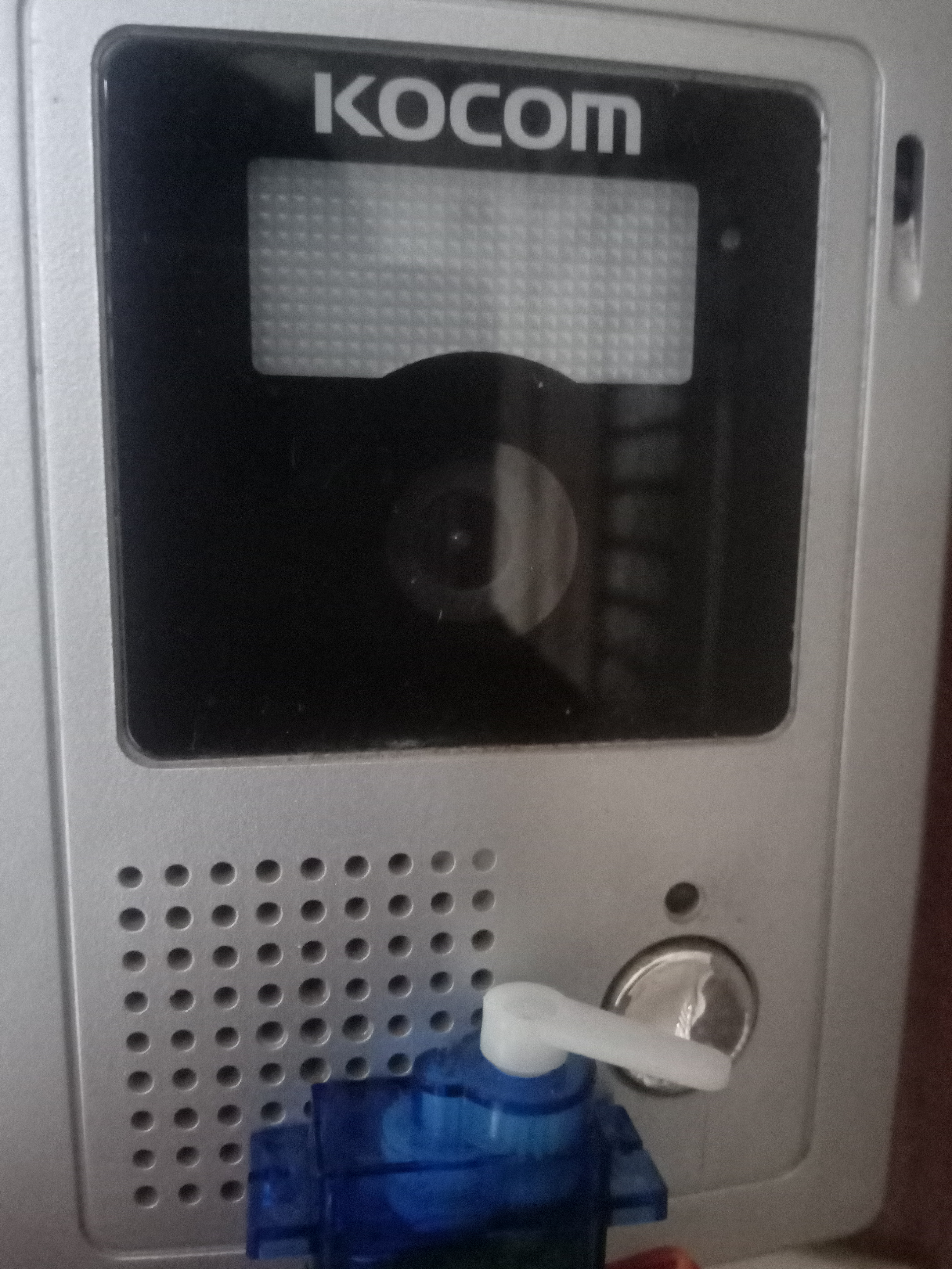 <図>
<図> 
これは、人が検出されたときにビデオをオンにするインターコムシステムの追加設定にすることができます。ただし、この追加のシステムは、既存のインターコムシステムに導入する必要があります。
既存のコードに追加された追加のコード:
  //人が検出されたときに緑色のLEDをオンにします。
 //人が検出されなかったときに赤色のLEDをオンにします
 if(person_score> no_person_score){
 digitalWrite(LEDG 、 低い); //ドアで人が検出されると、ブザーがオンになります
 digitalWrite(LEDR、HIGH); //家のLEDマトリックスは "person"を表示します
 digitalWrite(5、LOW);
 myDisplay.setTextAlignment(PA_CENTER);
 myDisplay.print( "Person");
 servo_8.write(0); //これはサーボを回転させることによってインターコムをオンにします
 delay(500);
 servo_8.write(180); //これは、サーボを回転させることによってインターコムをオフにします
 delay(100);
} else {
 digitalWrite(LEDG、HIGH);
 digitalWrite(LEDR、LOW);
サーボを回転させて既存のインターホンをオンにしてから元の場所に戻す機能を追加しました。
3番目のプロジェクト:自律型IoTベースの人の温度検知の自動化:
Arduinoの温度センサーは、プロセスまたは人体の温度を測定する場合の基本的な要素です。
Arduinoの温度センサーは、熱レベルを受け取って測定するために、接触しているか、近くにある必要があります。それが温度計の仕組みです。
これらの装置は、異常や病気が発生したときに人体で最初に変化する要因の1つであるため、病気の人の体温を測定するために非常に使用されます。
人体の温度を変化させる病気の1つはCOVID19です。したがって、主な症状を示します。
- 咳
- 倦怠感
- 呼吸困難(重度の場合)
- 発熱
発熱は、体温の上昇を主な特徴とする症状です。この病気では、これらの症状を常に監視する必要があります。
パンデミックにより、小売市場は大きな影響を受けました。モールやスーパーが再開した後は、入店したすべてのお客様の安全を確保する必要があります。この目的のために、手動の温度チェック技術が設定されています。 これにより、労力が増加し、温度をチェックしている人と温度をチェックしている人との接触のリスクも高まります。 これは次のように示されます:
<図>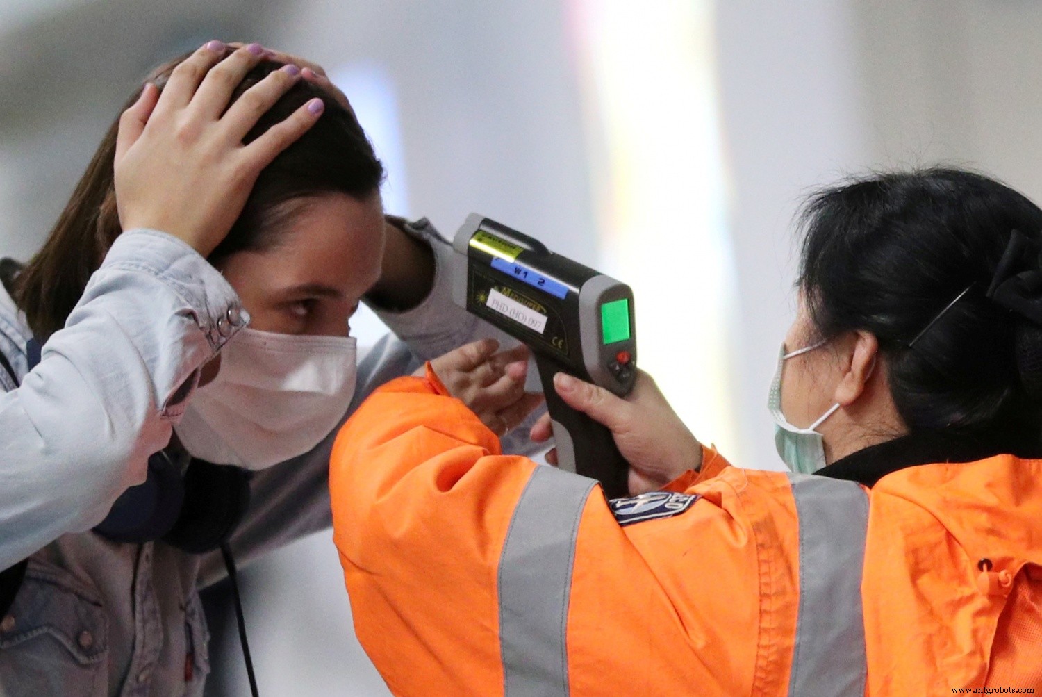
この画像は、2人の間で維持されている密接な接触または社会的距離の減少を示しています。
手動温度チェックシステムで直面している2番目の欠陥があります:
チェックされた温度については、これらの記録のデータは保存されていないか、測定された温度を監視するための外部デバイスと同期されていません。
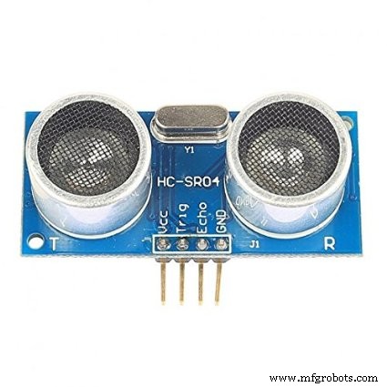
これらすべての短所を考慮して、Arduino MKR WiFi1010にデプロイされたArduinoベースのIoTソリューションを考え出しました。温度はAdafruitAMG8833温度モジュールを使用して測定されます。超音波センサーであるゲートで人が検出されると、その情報をArduino MKR WiFi 1010に送信して、温度データを取り込むようにAMG8833モジュールにコマンドを送信します。 モジュールはデータを正確にキャプチャし、データはリアルタイムでIoTダッシュボードに投影されます。人の異常な温度測定値が検出された場合、モールのセキュリティとスタッフが問題を即座に調査できるようにアラームが設定されます。収集されたデータにはそれぞれタイムスタンプが付けられ、 ThingSpeakダッシュボードで表示できます。 温度記録と時間グラフ データごとに。
同様に、スーパーマーケットやモールで異常な温度測定値が表示された日と時間範囲を追跡することもでき、それに応じてより多くのセキュリティ対策を実施できます。
下の画像は、セットアップを埋め込むことができる場所(セットアップをインストールできる領域)を示しています
<図>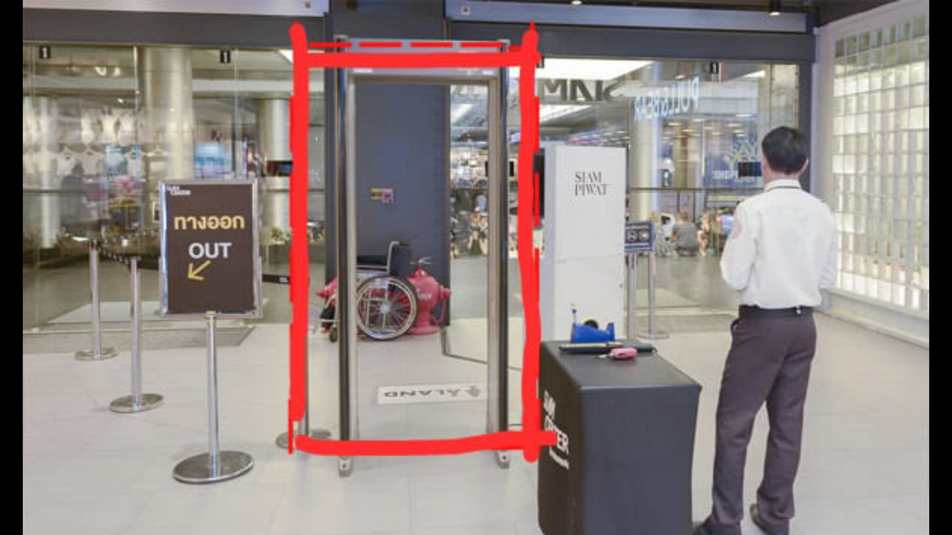
侵入確認ゲートには、人の侵入を検知し、20cmの範囲で人が検知された場合にArduino MKR WiFi1010にコマンドを送信するHC-SR04超音波センサーを設置することができます。 Arduinoマイクロコントローラーは同じコマンドをAMG8833温度モジュールに渡して、人の温度を読み取ります。この完全なプロセスは、超音波センサーが人を検出してから、温度を検出するために温度モジュールにコマンドを送信するまでに時間がかかります。したがって、遅延と同期するために、温度モジュールは超音波センサーから少し離れたところに取り付けられています。
人が入るたびにゲートが開きます(ここでは、プロトタイプではサーボを使用してゲートとして機能していますが、プロジェクトの今後の実装では、サーボは頑丈なゲートモーターに置き換えられますモータードライバーを介して制御され、Arduinoがコマンドを送信します)。 人の体温の読み取り値が取得され、この読み取り値がArduino WiFi 1010を介してリアルタイムでthingspeak IoTダッシュボードに送信されます。このため、モールの敷地内でアクティブなWi-Fi接続が必要です。これは、ほとんどの場合に通常利用できます。リサーチによると、発熱のある人の体温は約38.1℃、つまり104Fです。したがって、温度モジュールがこのしきい値を超える温度を検出すると、サーボが180度回転し、ブザーが鳴り続けて人について人々に警告します。同様に、警備員や他のモールのスタッフは、そのような場合に状況を管理するために時間内にその地域に到着することができます。
ロジックは次のように機能します:
<コード>├──PersonTemperatureDetection
├──HC-Sr04超音波センサー
│├──PersonDetection
││├──If(Person distance =20)、send command
├──Arduino MKR WiFi 1010
│├──超音波センサーがコマンドを送信する場合;
││├──ゲートを開く-サーボ(0)
││├──AMG8833をアクティブにする読み取り値を取得するには
││├──読み取り値をThingSpeakダッシュボードに送信します
││| ├──温度> 38.1Cの場合
│││| ├──ゲートを閉じる-サーボ(180)
││││├──ブザーを作動させる
││└──...ループを繰り返す
このようにして、温度モニターの完全なロジックが機能します。
温度モデルの回路図は次のとおりです。
<図>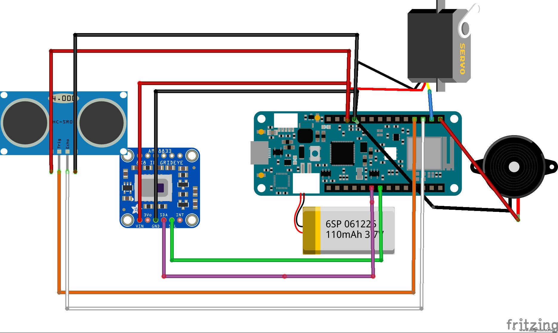
これは、プロジェクトで使用される完全なファームウェアとセットアップです
<図>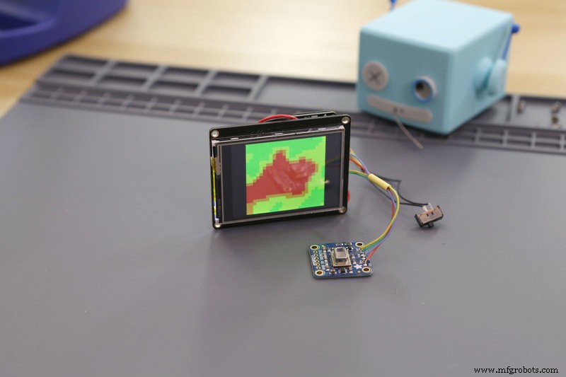
このシミュレーションは、AMG 8833サーマルカムによってキャプチャされたデータタイプを示しています。このデータは、コマンドを転送するためにArduino MKR WiFi1010に送信されます
<図>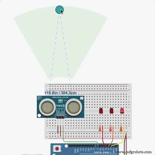
このシミュレーションは、超音波センサーによってキャプチャされた距離を示し、このコマンドはArduino MKR WiFiに送信され、AMG8833熱センサーをアクティブにします
サーボベースのドア開閉システムの代わりに、次のようにモータードライバーを使用してドアスライド開閉システムを自動化するコマンドシステムを実装します。
<図>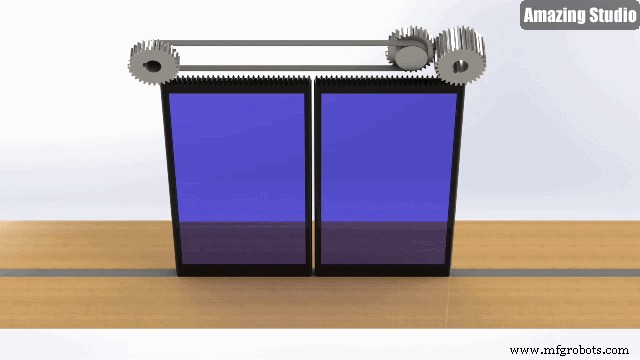
IoTダッシュボードの設定:
Thingsepak IoTダッシュボードセットアップの使用:
ThingSpeak™は、クラウド内のライブデータストリームを集約、視覚化、分析できるIoT分析サービスです。 ThingSpeakは、デバイスからThingSpeakに投稿されたデータを即座に視覚化します。 ThingSpeakでMATLAB®コードを実行する機能により、オンライン分析を実行し、データが入ってくるときにデータを処理できます。ThingSpeakは、分析を必要とするプロトタイピングおよび概念実証IoTシステムによく使用されます。
ThingSpeakはセットアップと使用が簡単だったので、私はそのダッシュボードを使用することを好みました。このインターフェースにより、ユーザーはダッシュボードをモール内のセキュリティ部門またはスタッフ部門と共有できるため、モールを訪れる人々を継続的に監視でき、同様に、温度リスクが高いと感じた特定の時間に制限を課すことができます。
<図>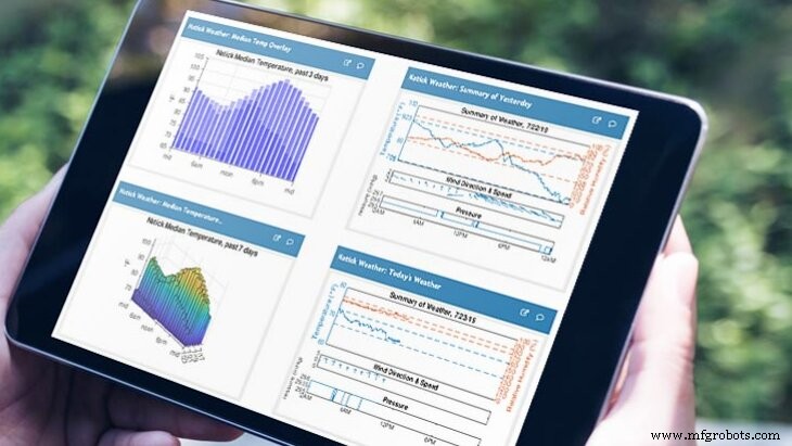
上の画像は、thingspeakダッシュボードの多様性と描かれた創造的な視覚化を表しています。
<図>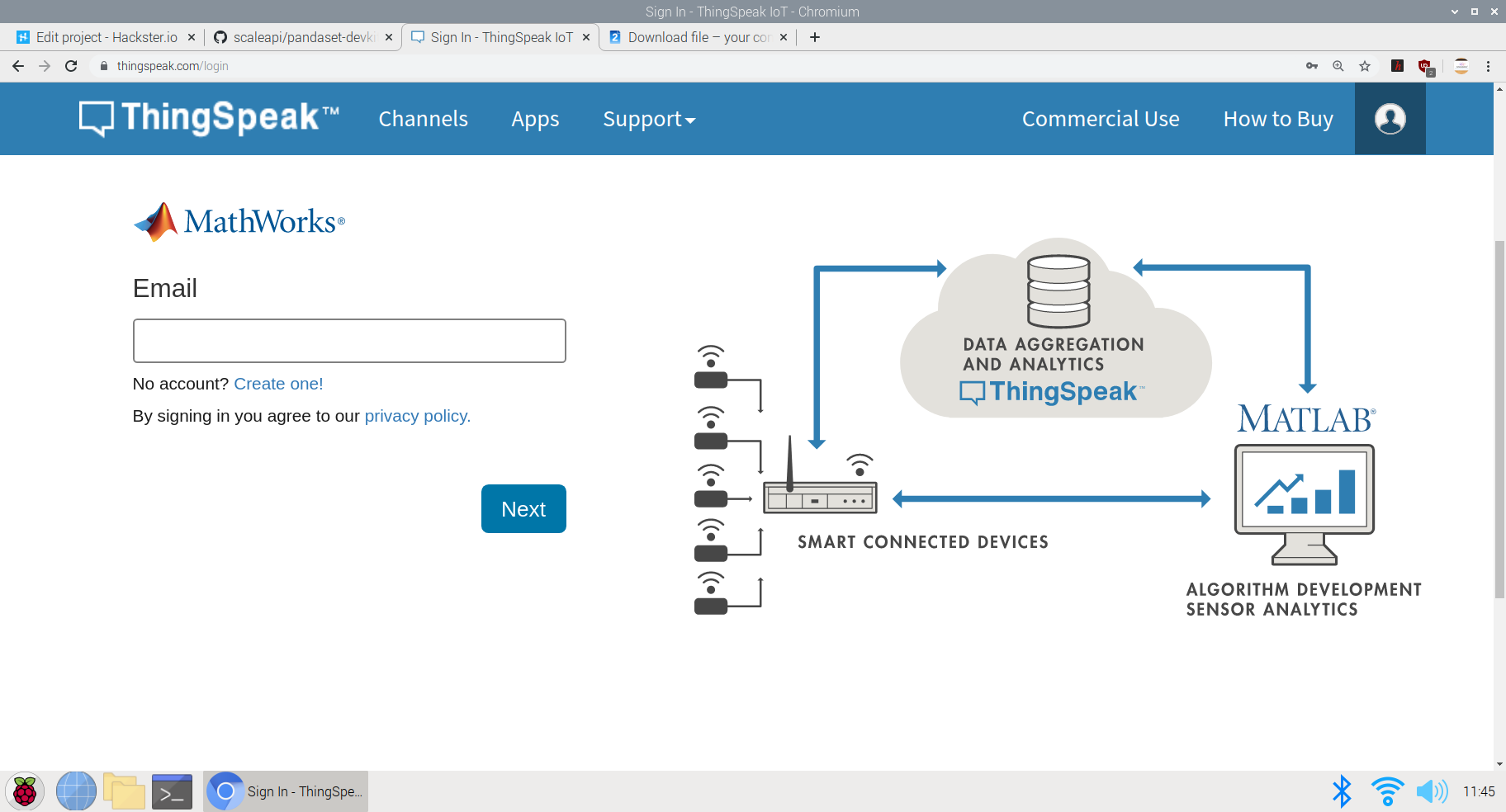
ThingSpeakIoTデータ収集プロセスで使用されるロジック
<図>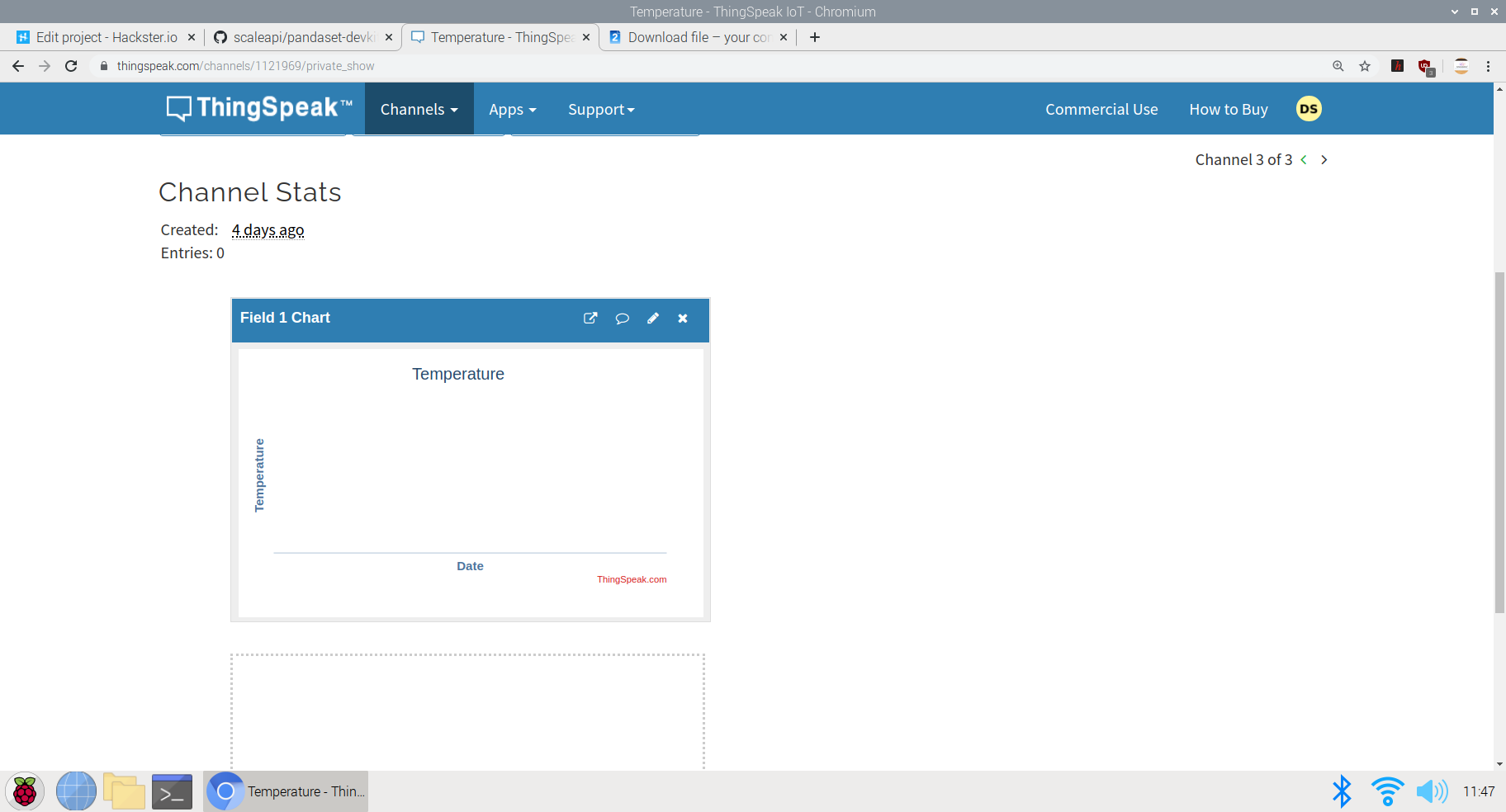
この画像は、さまざまなチャネルでの視覚化の作成を示しています。ここでは、視覚化セクションで温度と時間のグラフを作成しました。 AMG8833センサーによって収集されたデータには、それぞれタイムスタンプが割り当てられ、グラフにプロットされて、各データがキャプチャされた時間が表示されます。
収集されたデータは、こちらのパブリックダッシュボードでリアルタイムに表示できます。 ThingSpeak温度ダッシュボード
同様に、このプロットは、モールの訪問者に公開された単一のダッシュボードに累積的に統合して、モールに入る前に温度データを表示できます。訪問者が特定の日に異常な温度測定値を見つけた場合、安全のためにその日にスーパーマーケットやモールに行かないことを好む可能性があります。
視覚化統合データチャート:
このチャートは、特定の地域の他のモールやスーパーマーケットのチャートの読み取り値とともに単一のダッシュボードに埋め込むことができるため、ユニークな訪問者は、安全性の点で他のモールよりもパフォーマンスが優れているモールを確認でき、安全ガイドラインが守られ、入店する人々が発熱と診断されていないモールに行く。これは、政府がモールや小売セクターの再開とともに、人々の安全と信頼を確立するのに役立ちます
次のプロジェクトのコードは、GithubまたはArduinoWebエディターのいずれかで表示できます。温度-モデルコード
コードのロジックは次のようになります。
  #include
 #include
 #include
 #include ESP32_Servo.h
 #include
 #include
サーボサーボ1;
 int trigPin =9;
 int echoPin =8;
長距離;
 />長時間;

 WiFiMulti WiFiMulti;

 const char * ssid ="JioFiber-tcz5n"; // SSID(WiFiの名前)-これはダミーの名前です。ここにwifissidを入力してください
 const char * password ="**********"; //ここではパスワードについては触れていませんが、クリプトの実行中に、pwdについて言及することができます

 const char * host ="api.thingspeak.com/1121969";
 String api_key ="8LNG46XKJEJC89FE"; // thingspeakによって提供されるAPIキー


 Adafruit_AMG88xx amg;
ここでは、WiFiホストに必要なセットアップと、thingspeakの温度ダッシュボードのAPIキーとともに、いくつかのライブラリとファームウェアを定義しました。
進行中のコードの画像は次のとおりです。
<図>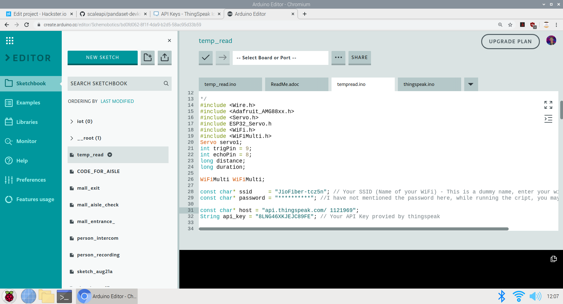
コードの次の部分は、実際のループが始まる前に必要なコンポーネントを設定することです。
これらは、実際のコードをループする前の前提条件です。サーボピンと超音波センサーを定義し、AMG 8833のテストを開始して、データを読み取れるかどうか、または接続されているかどうかを確認しました
  void setup()
 {
 Serial.begin(9600);
 servo1.attach(7);
 pinMode(trigPin、OUTPUT);
 pinMode(echoPin、INPUT); //セットアップコードをここに入力して、1回実行します:
}


 {
 Connect_to_Wifi();
 Serial.println(F( "AMG88xx test"));

 bool status;

 //デフォルト設定
 status =amg.begin();
 if(!status){
 Serial.println( "有効なAMG88xxセンサーが見つかりませんでした。配線を確認してください!");
 while(1);
}

 Serial.println( "-サーミスタテスト-");

 Serial.println();

 delay(100); //センサーを起動させます
}
次の部分は、完全な機能が実行されるボイドループです。ここでは、最初に一人一人が入ることができるようにゲートを開くように設定しました。 AMG 8833はデータ収集を実行し、内部に入ってくる人々の体温を読み取ります。温度が予想されるしきい値よりも高い場合、ゲートが閉じられ、アラーム(ブザー)がオンになって、人に警告し、人の立ち入りを許可しません
  void loop()
 ultra();
 Servo1.write(0);
 if(distance <=20){
 Serial.print( "サーミスタ温度=");
 Serial.print(amg.readThermistor());
 Serial.println(" * C ");

 Serial.println();
 //関数を呼び出してThingspeakにデータを送信します
 Send_Data();
 // delay
 delay(50);

 if(amg.readThermistor( )> 38.1)//熱を持っている人が検出された場合、彼は立ち入ることができません
 //熱を持っている人の平均体温は摂氏38.1度です
 servo1.write(180);
 digitalWrite(6、HIGH); //ブザーを鳴らして人々に警告します
}
最後の部分は、ThingSpeakダッシュボードにデータを送信することです:
ここでは、チャネルにフィールドが1つしかないため、すべてのデータがそのフィールドに送信されます。キャプチャされた amg.readThermistor() データはダッシュボードに送信されます。
  void Send_Data()
 {

 Serial.println( "Prepare to send data");

 // WiFiClientクラスを使用して作成TCP接続
 WiFiClientクライアント;

 const int httpPort =80;

 if(!client.connect(host、httpPort)){
シリアル。 println( "connection failed");
 return;
}
 else
 {
 String data_to_send =api_key;
 data_to_send + ="&field1 =";
 data_to_send + =string(amg.readThermistor());
 data_to_send + ="\ r \ n \";

 client.print( "POST / update HTTP / 1.1 \ n ");
 client.print(" Host:api.thingspeak.com \ n ");
 client.print(" Connection:close \ n ");
 client.print ( "X-THINGSPEAKAPIKEY:" + api_key + "\ n");
 client.print( "Content-Type:application / x-www-form-urlencoded \ n");
 client.print ( "Content-Length:");
 client.print(data_to_send.length());
 client.print( "\ n \ n");
 client.print(data_to_send);

 delay(2 00); //リアルタイムのデータ収集を実行するための遅延を減らしました
}

 client.stop();

}
<図> 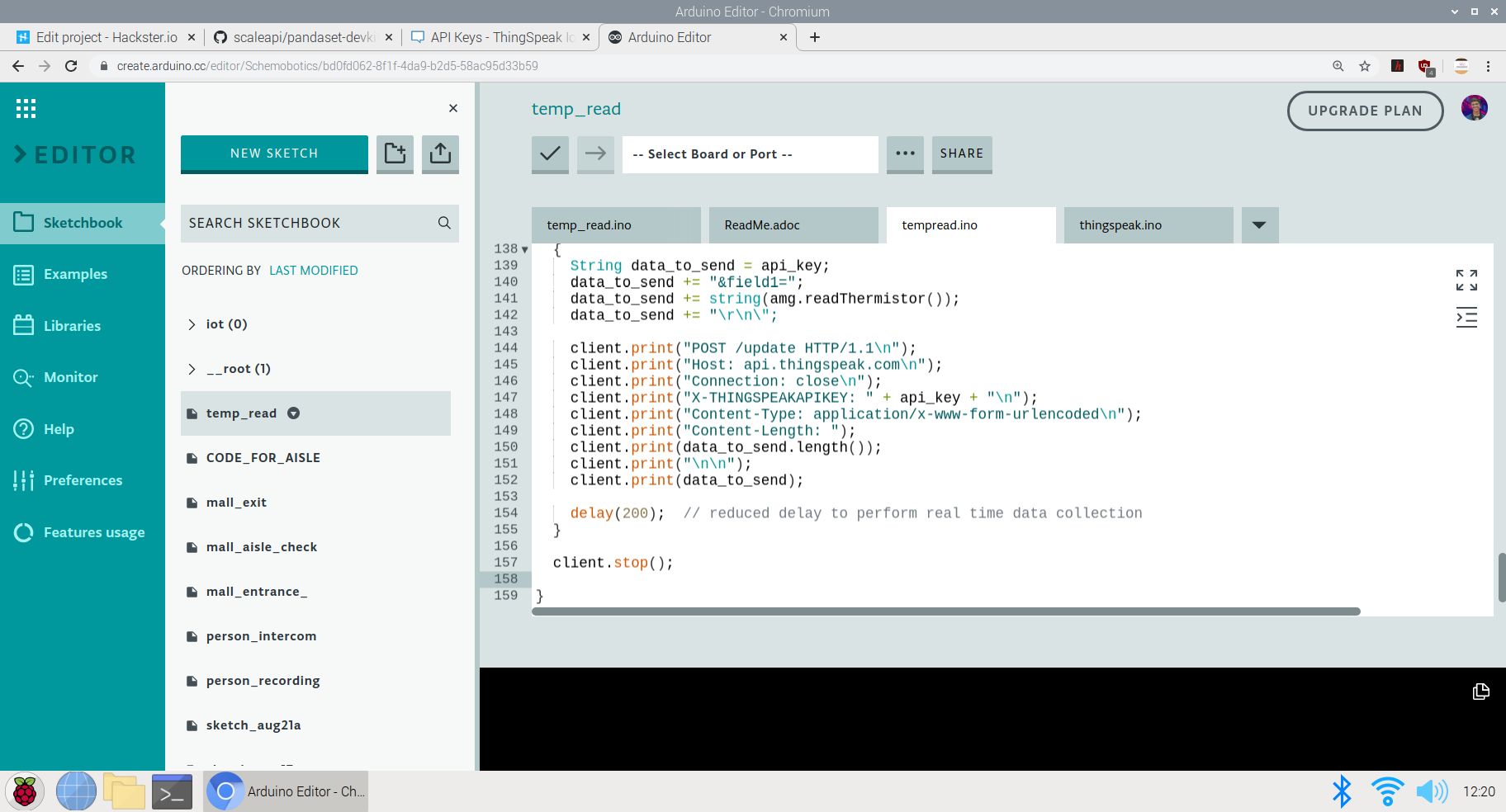
これでプロジェクトのコードセクションは終了です。次に、プロジェクトの使用法とGO TOMARKET部分の説明に進みます
<図>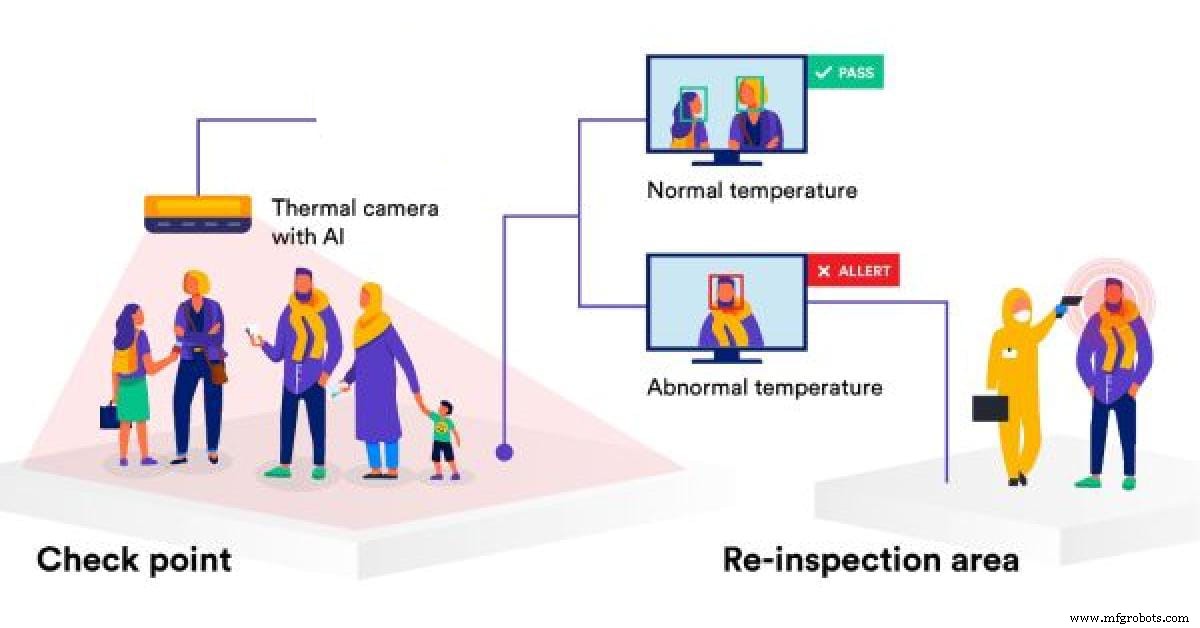 <図>
<図> 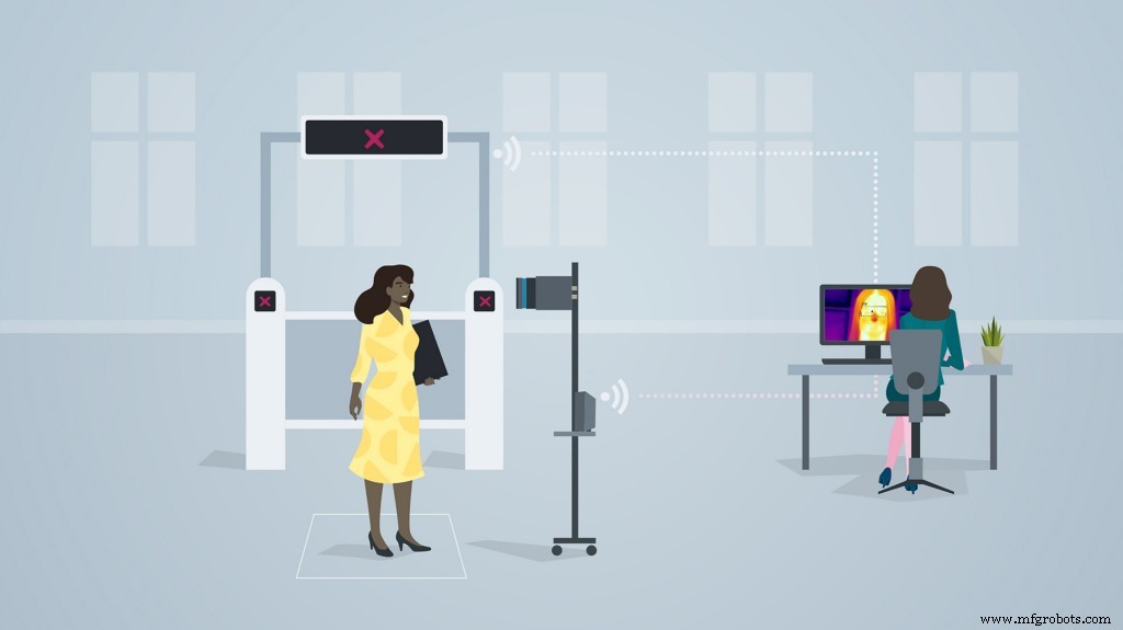
上の画像は、方法論の実装を示しています スーパーマーケットやモールでモデル化します。
市場と実用性に行く:
- モールやスーパーマーケットはこれを使用して異常温度データを特定でき、このデータは特定の日でも特定の時点で観察できます。
- このデータを使用して戦略を実装し、安全性とコンプライアンスを確保します。
- 労力を削減し、温度監視プロセスを自動化する
- 訪問者にダッシュボードを提供して、モールが安全かどうかを監視し、それに応じて最も安全な時点でモールを訪問します。
- この製品は、モールが安全な場所であることを訪問者に保証するために使用できるため、政府のガイドラインに従って売り上げと訪問を増やすことができます
- IoTベースのソリューションを提供する企業は、大量生産と流通のためにこの製品に投資できます。
- この製品を使用するスーパーマーケットが多いほど、政府へのデータへのアクセスが増え、顧客が地域で最も安全な場所を選択する選択肢が増えます。
- 手動の温度監視と比較して、人件費が削減され、温度を取得するために温度を測定する人が訪問者の近くにいる必要がある手動の監視と比較して感染率が低下するため、比較的手頃なソリューションです。
4番目のプロジェクト:Arduino 33 BLE SenseにデプロイされたTinyML&IoTベースのキュー監視および確立システム:
モールや小売セクターがオープンしたように、モールやスーパーマーケットでのキュー管理は大きな問題になっています。パンデミックのため、安全コンプライアンスを確保するために、モール内に入るのに一定の人数だけを制限する必要があります。しかし、これは手動で行われるため、労力が増加します。また、特定の時点でのモール内の人数のデータは、モールの訪問者には利用できません。このデータがモールの訪問者に利用可能になっていれば、モールを訪問する人々の割合が増加します。
進行中のコロナ危機の間に店やサービスを運営しようとすることは確かに挑戦です。顧客と従業員の安全を守りながら顧客にサービスを提供するのは難しいですが、デジタルキューイングはこの点で大いに役立ちます。仮想キューの背後にあるテクノロジーは完全に新しいものではありません。社会的距離の呼びかけは、彼らが提供する多くの利点のいくつかを浮き彫りにしているだけです。
ほとんどの国は、COVID-19の蔓延と戦うための法的措置を導入しています。新しい規制を遵守しながら顧客満足度を確保するには、確かなことが1つあります。それは、長い行列と混雑したロビーに行く必要があるということです。デジタルキューイング(仮想キューイングまたはリモートキューイングとも呼ばれる)テクノロジーにより、企業は、顧客が危害を加えられないようにしながら、タイムリーに顧客にサービスを提供できます。
一般的に、特定の小売環境では、次のタイプのキュー管理ソリューションが1つ以上見つかる可能性があります。
<図>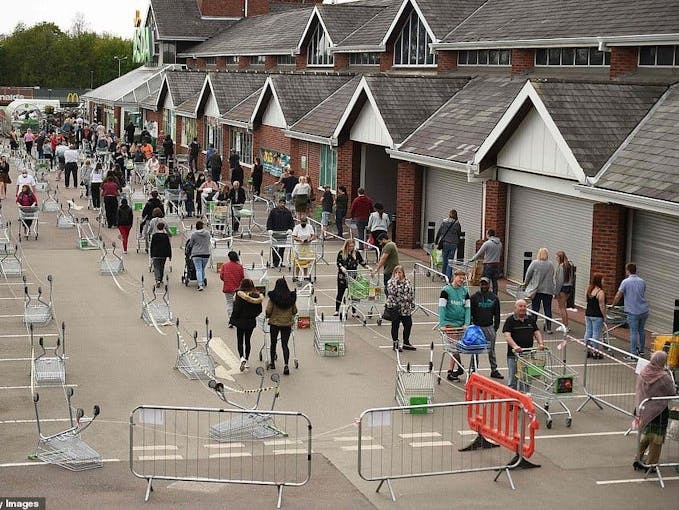
- 構造化キュー: 線は、固定された所定の位置に形成されます。例としては、スーパーマーケットのチェックアウトや空港のセキュリティキューがあります。
- 非構造化キュー: 線は、さまざまな場所と方向に自然かつ自発的に形成されます。例としては、タクシーの列や専門小売店でのコンサルタントの待機などがあります。
- キオスクベースのキュー: 到着した顧客は基本情報をキオスクに入力し、スタッフがそれに応じて対応できるようにします。キオスクは、銀行だけでなく、医療施設や政府施設でもよく使用されます。
- モバイルキュー: 顧客は、物理的に列に並ぶのではなく、スマートフォンを使用します。店舗で待つ必要はありませんが、IoTダッシュボードを監視して店舗での待ち時間を確認できます。
長い行列は、構造化されているかどうかに関係なく、多くの場合、持ち込み客が店に入るのを思いとどまらせます。さらに、それらは生産性を制限し、顧客とスタッフに過度のストレスレベルを引き起こします。
効果的なキュー管理は、カスタマーエクスペリエンスに直接影響しますか?
並んで待つという経験には興味深い側面があります。私たちが感じる待ち時間は、実際に並んで過ごした時間と一致しないことがよくあります。実際には平均待機時間を超えているにもかかわらず、ある期間が通常よりも「長い」と誤って見なされたり、別の期間が「短い」と見なされたりする場合があります。ほとんどの場合、これは待機時間を埋める方法と関係があります。
「占有時間(手荷物受取所まで歩く)は、占有時間(カルーセルに立っている)よりも短く感じます。待ち行列に関する調査によると、平均して、人々は列に並んで待っている時間を約36パーセント過大評価しています。」
<図>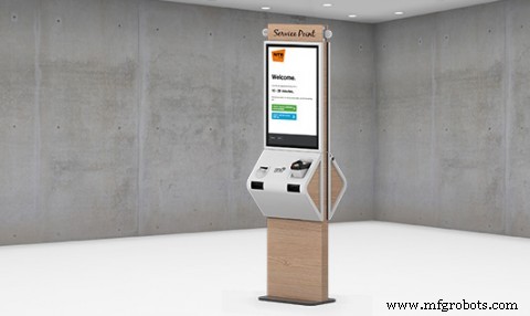
顧客がスーパーマーケットに行くことを恐れる主な理由は、データが不十分であるという問題です。訪問者はモール内の人々の密度を知りません。モール内の人数が多いほど、モールを訪れるリスクが高くなります。モールに出入りする人数を手動で計算し、このデータをリアルタイムで更新することはできません。また、訪問者は、いつ、どの時間にモールを訪れるのが最適かを知りません。また、訪問者は各モールの待ち時間がわからないため、待ち時間が短い場合は近くの他のスーパーマーケットに行くことができます。結果として、これらすべてが人々の回心を減らし、それに応じてモールを訪れる人々の数を減らします。 If the visitors have the access to population data, they have a sense of trust and leads to increase in sales of malls. Hence, I've come up with an Arduino Based TinyML and IoT solution to make this data available to the visitors and also increase the conversion of visitors in the mall by following the necessary safety guidelines. If the visitors have the access to population data, they have a sense of trust and leads to increase in sales of malls. Hence, I've come up with an Arduino Based TinyML and IoT solution to make this data available to the visitors and also increase the conversion of visitors in the mall by following the necess
This solution is based on computer vision and person detetction algorithm based on tensorflow framework.
It functions in the following way :
This solution is implemented on the gates of the mall or the supermarket. The Arducam mini 2mp keeps capturing image data and sends it to the Arduino 33 BLE Sense to process and classify this data. If a person is detected, The arduino increases the count of the stored data of number of people inside the mall by 1. Since a person is detected, the Servo motor rotates, opening the entrance to allow the person inside. For each person allowed inside, the data is sent to the ThingSpeak IoT dashboard which is open for the vistors to view.
When the person count increases the 50 threshold limit(This threshold can be altered depending upon the the supermarket size), the gate is closed and a wait time of 15min is set until the customers inside exit the store. The wait time is then displayed on the LED matrix display screen so that the customers in the queue can know the duration they have to wait for.
The people can also keep a track of the number of people inside the store. The number of people allowed to enter inside the store at a single time is 50 people.
The physical queuing unit of this product, helps in establishing queues while the IoT Dashboard helps in projecting the total count of the customers going in the store and total count of the customers going out of the store. Currently this is the dashboard data that will be displayed but I am working on a logic for displaying the waiting time required for the customer to get inside the mall. The logic for it is pretty simple, it depends on the number of people inside the mall. The total no of people entering the mall displayed on dashboard minus the total no of people exited the mall displayed on the dashboard. This will give us an outcome of the total no of people inside the store. The next operation would be the total no of people outside the store subtracted by the threshold (limit that the store can accommodate). If the outcome is a negative integer, the waiting time would be multiplication of the negative integer by the negative of the average time a person spends inside the store. If the outcome of the operation would be a positive integer, the wait time would be none.
Heading towards the implementation of the physical queuing system:
このモデルの設計には、次のソフトウェアが使用されています。
- TensorFlow lite
- ThingSpeak
- ArduinoWebエディター
In this person detection model, I have used the Pre-trained TensorFlow Person detection model apt for the project.この事前トレーニング済みモデルは3つのクラスで構成されており、そのうち3番目のクラスには未定義のデータセットが含まれています。
"unused"、
"person"、
"notperson"
In our model we have the Arducam Mini 2mp plus to carry out image intake and this image data with a decent rate of fps is sent to the Arduino Nano 33 BLE Sense for processing and and classification. Since the Microcontroller is capable of providing 256kb RAM, we change the image size of each image to a standard 96*96 for processing and classification. The Arduino Tensorflow Lite network consists of a deep learning framework as:
- Depthwise Conv_2D
- Conv_2D
- AVERAGE Pool_2D
- フラットレイヤー
This deep learning framework is used to train the Person detection model.
The following is the most important function defined while processing outputs on the Microcontroller via Arduino_detetction_responder.cpp
// Process the inference results.
 uint8_t person_score =output->data.uint8[kPersonIndex];
 uint8_t no_person_score =output->data.uint8[kNotAPersonIndex];
 RespondToDetection(error_reporter, person_score, no_person_score);
In the following function defining, the person_score , the no_person_score have been defined on the rate of classification of the data.
using these defined functions, I will be using it to give certain outputs on the basis of confidence of the person-score and the no_person_score 。
The detection responder logic of the code works in the following way:
├── Person Detection and responder - Entry
├── Arducam mini 2MP Plus
│ ├──Image and Video Data to Arduino
├── Arduino BLE 33 Sense
│ ├── processing and classification of the input data
│ │ ├── If person detected, open the gate - servo(180)
│ │ ├── If no person detected, close the gate - servo(0)
│ │ ├── Send the number of people entered count to to ThingSpeak Dashboard via ESP8266 -01
│ │ | ├── If people count has exceeded 50
│ │ │ | ├── Close the gate &wait for 15min to let the people inside move out
│ │ │ │ ├── Display wait time on a LED Matrix
│ │ └── ...Repeat the loop
├── Person Detection and responder - Exit
├── Arducam mini 2MP Plus
│ ├──Image and Video Data to Arduino
├── Arduino BLE 33 Sense
│ ├── processing and classification of the input data
│ │ ├── If person detected, open the gate - servo(180)
│ │ ├── If no person detected, close the gate - servo(0)
│ │ ├── Send the number of people entered count to to ThingSpeak Dashboard via ESP8266 -01
│ │ └── ...Repeat the loop
Adhering to the logic used in the model, the Arducam mini 2mp plus will continuously capture Image data and sends this data to the Arduino 33 BLE Sense to process and classify the data. The overall model size is 125KB. If a person has been detected, the Arduino sends the command to the servo to rotate to servo to 180degree. If a person is not detected, the servo is rotated to 0degree and the gate is closed. Each time a person is detected, the the count increments by 1. If the count exceeds the 50 threshold, no more person is allowed inside and a wait time of 15min is set.
The wait time is continuously displayed and updated on the LED Matrix dislplay.
This count is also displayed on the ThingSpeak IoT dashboard via the ESP8266 01
Through the Dashboard, an individual can easily view the number of people are inside at a given day at a given point of time.
At the exit gate, the same logic is set. If a person is detected, the gate is opened while if no person is detected, the gate is closed. Each time a person is detected, the count increases by 1. This count is displayed on the ThingSpeak IoT dashboard.
In this way one can monitor the number of people entering and the number of people exiting.
Since the two models for entry and exit are deployed on two different microcontrollers, calculating the average wait time based on data from different microcontroller is a bit hard, but this uses a simple logic function.
x =No of people who have entered
Y =No of people who have exited
X - Y =No of people who are inside the mall
Z =Threshold of the no of people who are allowed to be inside the mall
let Z-(X-Y) =count {this is the number of people (in negative) who have either crossed the threshold limit or are below the threshold limit
If "count" is negative, The wait time is equal to count*(the negative of the average time a person spends inside the mall)
if "count" is positive, the wait time is zero
In this way, the average queue time calculating algorithm is imposed.
Working of the Firmware:
<図>
This is the complete setup of the firmware designed on Fritzing.
This model comprises of the following firmware used:
- Arduino 33 BLE sense - Used to process the data gathered, classifies the data processes, sends the command according to the logic fed.
- MG959 / MG995 Servo - Heavy duty servo( An external power supply may be applied) - To open and close the gates as per microcontroller command.
- Arducam Mini 2mp plus - Continuous Raw data image accumulation from source.
- Adafruit lithium ion charger - Used to deliver charge through the lithium battery
- Lithium ion Battery - power source
- ESP8266 - 01 - Used for sending data to the ThingSpeak dashboard via WiFi network.
- MAX7219 4 in 1 display - Used for displaying the wait time on the display screen.
Functioning and Working of Logic in Code:
The following are the Libraries included in themain.ino code for functioning of the model.
#include

#include "main_functions.h"

#include "detection_responder.h"
#include "image_provider.h"
#include "model_settings.h"
#include "person_detect_model_data.h"
#include "tensorflow/lite/micro/kernels/micro_ops.h"
#include "tensorflow/lite/micro/micro_error_reporter.h"
#include "tensorflow/lite/micro/micro_interpreter.h"
#include "tensorflow/lite/micro/micro_mutable_op_resolver.h"
#include "tensorflow/lite/schema/schema_generated.h"
#include "tensorflow/lite/version.h"
In the following code snippet, the loop is defined and performed. Since this is the main.ino code, it controls the core functioning of the model - used to run the libraries in the model.
void loop() {
 // Get image from provider.
 if (kTfLiteOk !=GetImage(error_reporter, kNumCols, kNumRows, kNumChannels,
 input->data.uint8)) {
 TF_LITE_REPORT_ERROR(error_reporter, "Image capture failed.");
 }

 // Run the model on this input and make sure it succeeds.
 if (kTfLiteOk !=interpreter->Invoke()) {
 TF_LITE_REPORT_ERROR(error_reporter, "Invoke failed.");
 }

 TfLiteTensor* output =interpreter->output(0);

 // Process the inference results.
 uint8_t person_score =output->data.uint8[kPersonIndex];
 uint8_t no_person_score =output->data.uint8[kNotAPersonIndex];
 RespondToDetection(error_reporter, person_score, no_person_score);
}
In the following code snippet, the necessary libraries required to inference the image to be captured is displayed. The images after captured are converted to a 96*96 standardised size which can be interpreted on the arduino board.
Here, the Arducam mini 2mp OV2640 library has been utilised.
This code has been provided in the arduino_image_provider.cpp snippet
#if defined(ARDUINO) &&!defined(ARDUINO_ARDUINO_NANO33BLE)
#define ARDUINO_EXCLUDE_CODE
#endif // defined(ARDUINO) &&!defined(ARDUINO_ARDUINO_NANO33BLE)

#ifndef ARDUINO_EXCLUDE_CODE

// Required by Arducam library
#include
#include
#include
// Arducam library
#include
// JPEGDecoder library
#include

// Checks that the Arducam library has been correctly configured
#if !(defined OV2640_MINI_2MP_PLUS)
#error Please select the hardware platform and camera module in the Arduino/libraries/ArduCAM/memorysaver.h
#endif

// The size of our temporary buffer for holding
// JPEG data received from the Arducam module
#define MAX_JPEG_BYTES 4096
// The pin connected to the Arducam Chip Select
#define CS 7

// Camera library instance
ArduCAM myCAM(OV2640, CS);
// Temporary buffer for holding JPEG data from camera
uint8_t jpeg_buffer[MAX_JPEG_BYTES] ={0};
// Length of the JPEG data currently in the buffer
uint32_t jpeg_length =0;

// Get the camera module ready
TfLiteStatus InitCamera(tflite::ErrorReporter* error_reporter) {
 TF_LITE_REPORT_ERROR(error_reporter, "Attempting to start Arducam");
 // Enable the Wire library
 Wire.begin();
 // Configure the CS pin
 pinMode(CS, OUTPUT);
 digitalWrite(CS, HIGH);
 // initialize SPI
 SPI.begin();
 // Reset the CPLD
 myCAM.write_reg(0x07, 0x80);
 delay(100);
 myCAM.write_reg(0x07, 0x00);
 delay(100);
 // Test whether we can communicate with Arducam via SPI
 myCAM.write_reg(ARDUCHIP_TEST1, 0x55);
 uint8_t test;
 test =myCAM.read_reg(ARDUCHIP_TEST1);
 if (test !=0x55) {
 TF_LITE_REPORT_ERROR(error_reporter, "Can't communicate with Arducam");
 delay(1000);
 return kTfLiteError;
 }
The final part where in the complete model is controlled is the Arduino_detection_responder.cpp.
This is a small code snippet of the entire logic used. When the confidence score of a person is greater than the confidence score of no person, the gate is opened and it is assumed that the person is detected. For this purpose the servo is moved to 0Degree to open the gate. On the detection of a person, the count is incremented by 1 =initially which began at 0. This count indicates the number of people coming inside. The num value of the count is sent to the ThingSpeak IoT dashboard which represents the number of people entering. When the count reaches the value of 50; the gate is closed and a wait time of 15min is imposed on the queue. The gate is closed and wait time is imposed each time 50 people enter. For this a logic of multiples of 50 is set
// Switch on the green LED when a person is detected,
 // the red when no person is detected
 if (person_score> no_person_score) {
 digitalWrite(LEDG, LOW);
 digitalWrite(LEDR, HIGH);
 servo_8.write(0); // this servo moves to 0degrees in order to open the mall door when a person is detected to ensure no touch entry system
 count++

 } else {
 digitalWrite(LEDG, HIGH);
 digitalWrite(LEDR, LOW);
 servo_8.write(180); // this servo moves to 180degrees when no person is detected
 }

 TF_LITE_REPORT_ERROR(error_reporter, "Person score:%d No person score:%d",
 person_score, no_person_score);
}


// Now we have let in 50people inside the store, so we set a delay of 15min wait time for others waiting outside to let them in
// Displaying wait time on the screen every 1min

 if(count =y*50) // when people are detected in multiples of 50, we instruct it to start displaying wait time to other people to wait until 15 min
 myDisplay.setTextAlignment(PA_CENTER);
 myDisplay.print("Waiting 15min");
delay(60000); 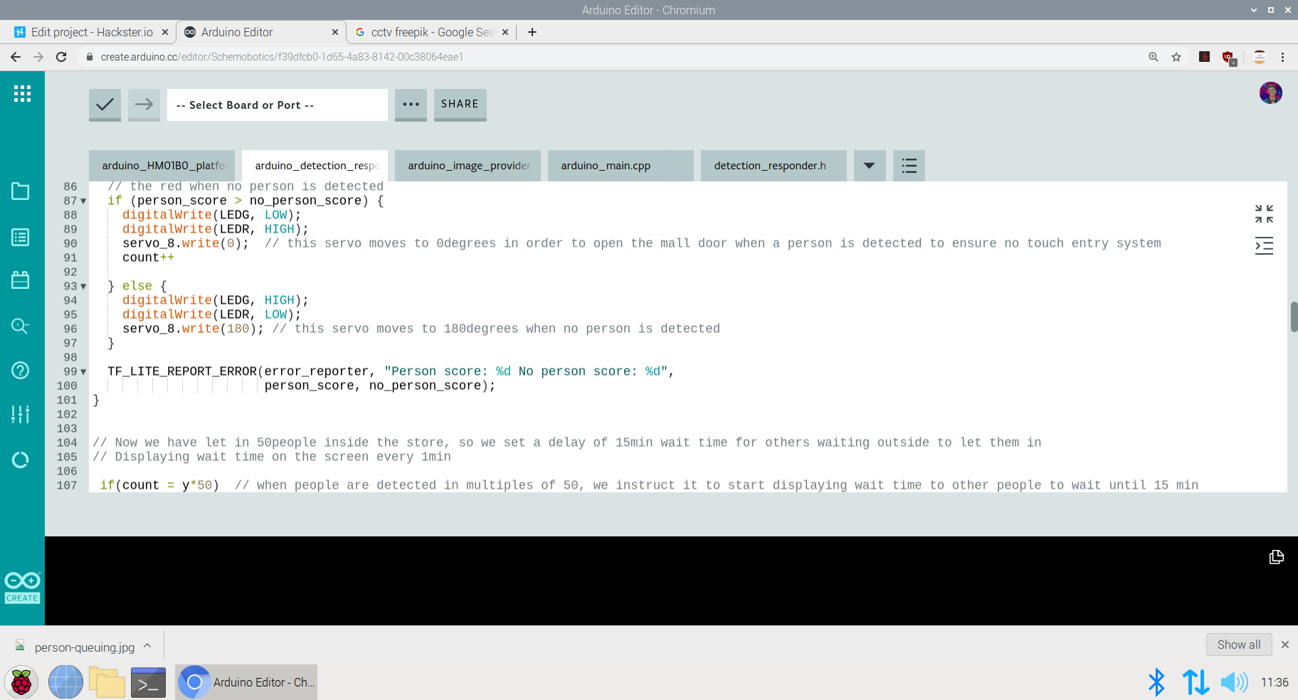
Setting up the ThingSpeak Dashboard:
Since the features in Thingspeak Dashboard are limited, I will not be implementing the Time prediction algorithm right now but I am working on the logic to communicate and write data from the Dashboard to microcontroller to perform the time calculation algorithm.
In the ThingSpeak Dashboard, I have added two fields; one for entry and the other one for exit.
The co-ordinates for the store or mall for which the queuing system is displayed, is also added in the form of a map.
The data displayed for the first field is gathered through the entry responding logic and the data displayed for the second field is gathered through the exit responding logic.
<図>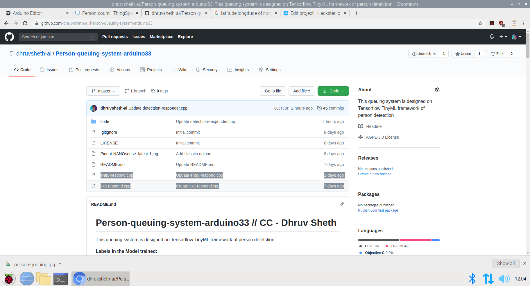
This is the snip of the two different logics used in the model.
The ThingSpeak Dashboard can be made available to the the staff of the store to check the number of people entering the store in real time and the number of people exiting the store in real time. This data can also be observed to see the analysis of the data at a given day at a a given time to check and impose further restrictions if required if the limit of people in the store exceeds the expected number of people at a given day
<図>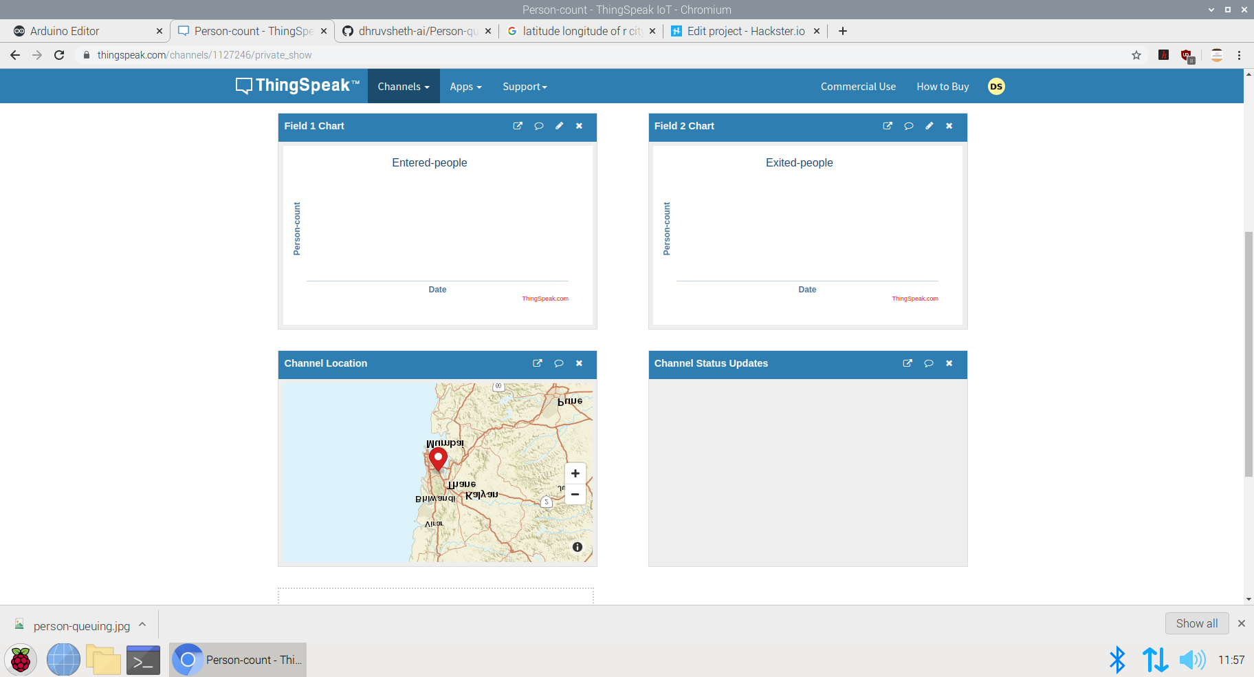
This Dashboard can be viewed here:IoT Dashboard
The following represents the field created for this purpose.
Now, a question might arise that for person detection model that this model can be replaced by ultrasonic or infrared sensors. Flaws in Ultrasonic Sensors or Infrared Based Sensors:These sensors are not exactly accurate and for the real time person count display, these sensors may provide wrong readings. Also, these sensors add as additional hardwares while in Go to Market Solutions, the person detection algorithm can be implemented in existing cameras and can reduce hardware cost. The data from these cameras could be sent to the Arduino BLE sense for central Classification and data processing.
<図>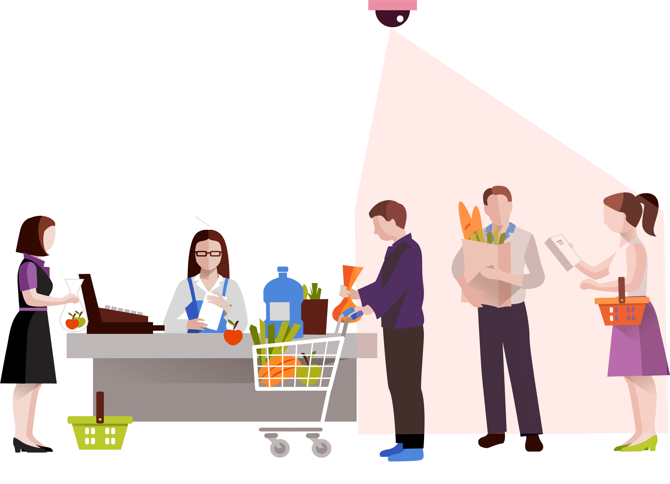
GO TO MARKET &PRACTICALITY: <図>
- Malls and Supermarkets can use this to identify The count of people entering and exiting the mall in real time.
- Implement Strategies using this data to ensure Safety and Compliance with efficient Queue management algorithms.
- Decrease Labour and automate Queue Management Process
- Offer Dashboard to the visitors to monitor the density of people inside the mall and accordingly visit the mall at the safest point of time.
- This product can be used to ensure the visitors that the mall is a safe place and hence, can increase the sales and visits following Government guidelines
- Companies offering Ai and IoT based solutions can invest for mass production and distribution.
- The more the supermarkets using this product, the more the access to data to the government and more the choice to customers to select the preferable safest place in their locality along with the the queue time required for each store can be monitored. This will lead to a wide range of options of supermarkets in the locality comparing the queue time and safety.
- Comparatively affordable solution as compared to manual queuing system and updating information manually to the Dashboard.
- Utilize real-time CCTV footage to impose Queue management in a mall/shop through person detection in terms of timely trends and spatial analysis of person density in the mall.
- Enable Stores to make better, data-driven decisions that ensure your safety and efficient Queues based on autonomous queuing system.
Github Code:Arduino Autonomous TinyML and IoT based queuing system.
Addition to the Existing Person Detection Algorithm- Mask Detection System:
Mask Detection Model based on TinyML :
Dr. Kierstin Kennedy, chief of hospital medicine at the University of Alabama at Birmingham, said, “Masks can protect against any infectious illness that may be spread by droplets. For example, the flu, pertussis (whooping cough), or pneumonia.”
Adding that wearing a cloth mask has benefits beyond slowing the spread of COVID-19, and that source control can reduce the transmission of many other easily spread respiratory infections — the kind that typically render people infectious even before they display symptoms, like influenza.
Until the threat of this pandemic has been neutralized, people should embrace the protection masks allow them to provide to those around them.
After all, it’s not necessarily about you — it’s about everyone you come in contact with.
It’s not at all uncommon to be an asymptomatic carrier of the new coronavirus — which means that even if you have no symptoms at all, you could potentially transmit the virus to someone who could then become gravely ill or even die.
Adhering to this, I decided to increase the necessity of wearing face-masks along with touch-free systems to increase safety in malls and supermarkets. Along with the person detection algorithm, I decided to make a custom face mask detection model which detects face masks and displays this data on the ThingSpeak IoT dashboard to increase awareness among mall staff as well as the visitors coming inside so that they are aware of the time trends when the most number of people are without masks. Through this there is a increases of sense of warning and awareness in people to wear masks. Accordingly, the store staff can keep a monitor on these trends and increase restrictions based on data driven statistics.
Deciding upon the Logic and Dataset of the Model:
<図>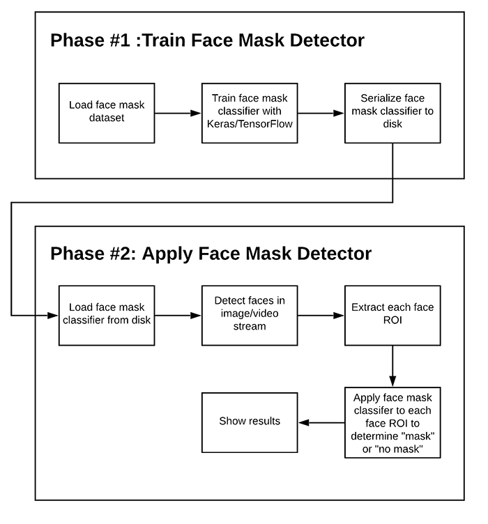
This is an overall Logic used in most of face mask detection algorithms. Since, we are deploying this model to an Arduino 33 BLE Sense, the deployment process of this model will vary.
There are two steps involved in constructing the model for Face Mask Detection.
- Training: Here we’ll focus on loading our face mask detection dataset from disk, training a model (using Keras/TensorFlow) on this dataset, and then serializing the face mask detector to disk
- Deployment: Once the face mask detector is trained, we can then move on to loading the mask detector, performing face detection, and then classifying each face as
maskorno_mask
Dataset used in training this model:
<図>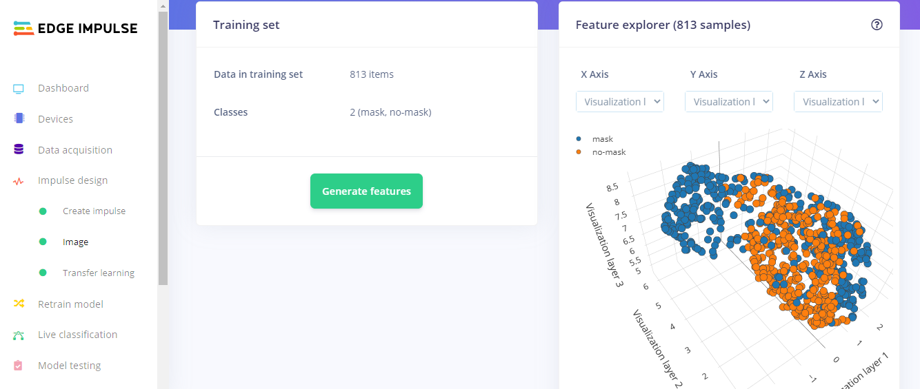
The dataset used in this process consists of 3500 images but to reduce the size of the model, and feed in accurate model images, I have used 813 images to increase accuracy of the model by decreasing bulk size. This model is an average 676K in size and utilizes nearly 440.3K Ram. Since this model is the optimized version of the original model, the accuracy of the model is 87.47% as compared to 98.15% in the non-optimized one.
<図>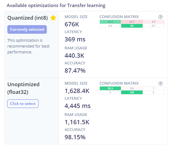
このモデルの設計には、次のソフトウェアが使用されています。
- TensorFlow lite
- ThingSpeak
- Arduino Web Editor
Heading towards designing the model in EdgeImpulse Studio:
Powerful deep learning models (based on artificial neural networks) are now reaching microcontrollers.過去1年間で、マイクロコントローラー用のTensorFlow Lite、uTensor、ArmのCMSIS-NNなどのプロジェクトを通じて、ディープラーニングモデルをより小さく、より速く、組み込みハードウェア上で実行できるようにすることに大きな進歩がありました。ただし、高品質のデータセットの構築、適切な機能の抽出、これらのモデルのトレーニングと展開は、依然として複雑になる可能性があります。
Edge Impulseを使用すると、実際のセンサーデータをすばやく収集し、クラウドでこのデータを使用してMLモデルをトレーニングし、モデルをArduinoデバイスにデプロイできるようになりました。 From there you can integrate the model into your Arduino sketches with a single function call.
Step 1 - Acquisition of Data in the Edge Impulse Studio:
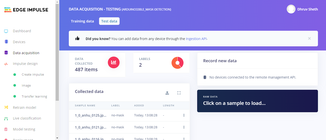
Using the dataset of 3500 images, I filtered these images to the best performing images and finally fed in 813 images totally in the Training Data and 487 images in the testing Data. I labelled these classes as mask and no_mask.
Then, I went ahead creating an impulse design which best suited the Model type. For optimal accuracy its recommended to use a standard image size which is 96*96 and also works the best on the Arduino 33 BLE Sense. Since the input type was images, I went ahead and selected "images" in the processing block. For the transfer learning block, the type recommended for image learning is Transfer Learning (Images) which is a Fine tune a pre-trained image model on your data. with Good performance even with relatively small image datasets.
<図>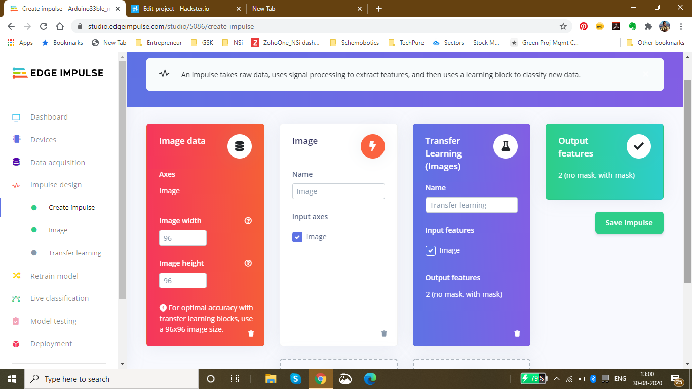
The next step was saving the parameters based on color depth. Here, I have selected RGB because in the dataset I am using for mask detection, color is also an important feature of classification instead of grayscale. In this page, we can also see the raw features with the processed features of the image
<図>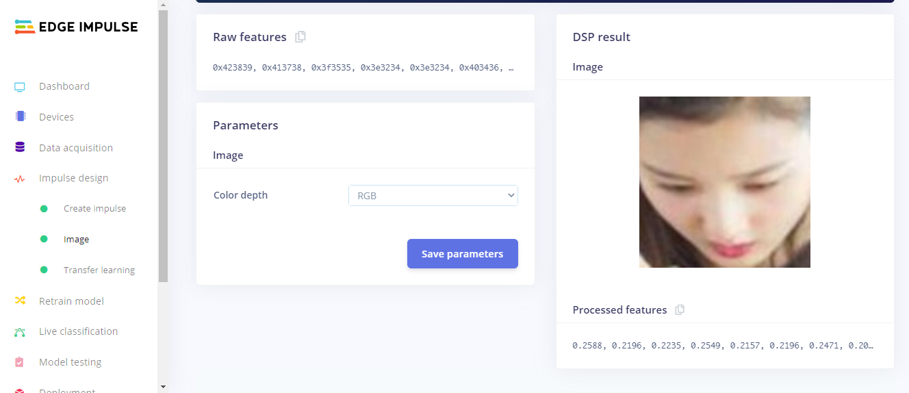
After Feature Generation I obtained the classification graph or the feature explorer where I could see the classes based on their classifications. The blue dots represent mask images and the orange dots represent the no_mask images.
In this feature generation, I obtained a fair classification with a distinct classification plot.
<図> Finally, Moving on to the Transfer Learning Plot:
Here, I set the number of training cycles/epochs as 30 to get the highest accuracy with minimum val_loss. It so happens that if we train the model based on many training cycles, the accuracy graph starts to decrement after a certain number of epochs and the val_loss increases. Therefore I decided to limit the epochs to 30 which proved to be perfect. The learning rate is set to 0.0005 which is the default and proves to be the most appropriate. Here, I have used the MobileNetV2 0.35 (final layer:16 neurons, 0.1 dropout) model because this model is comparitively lightweight and accurate.
<図>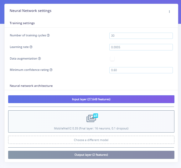 <図>
<図> 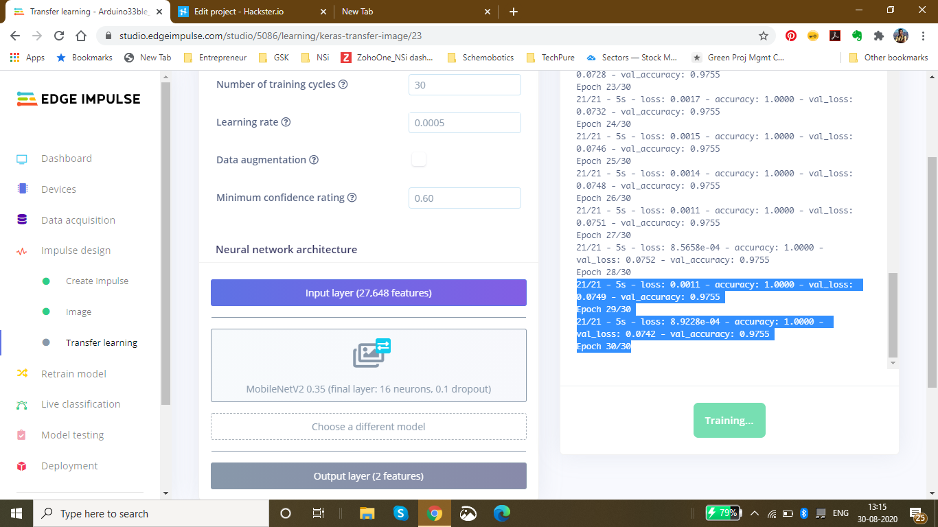 <図> <図>
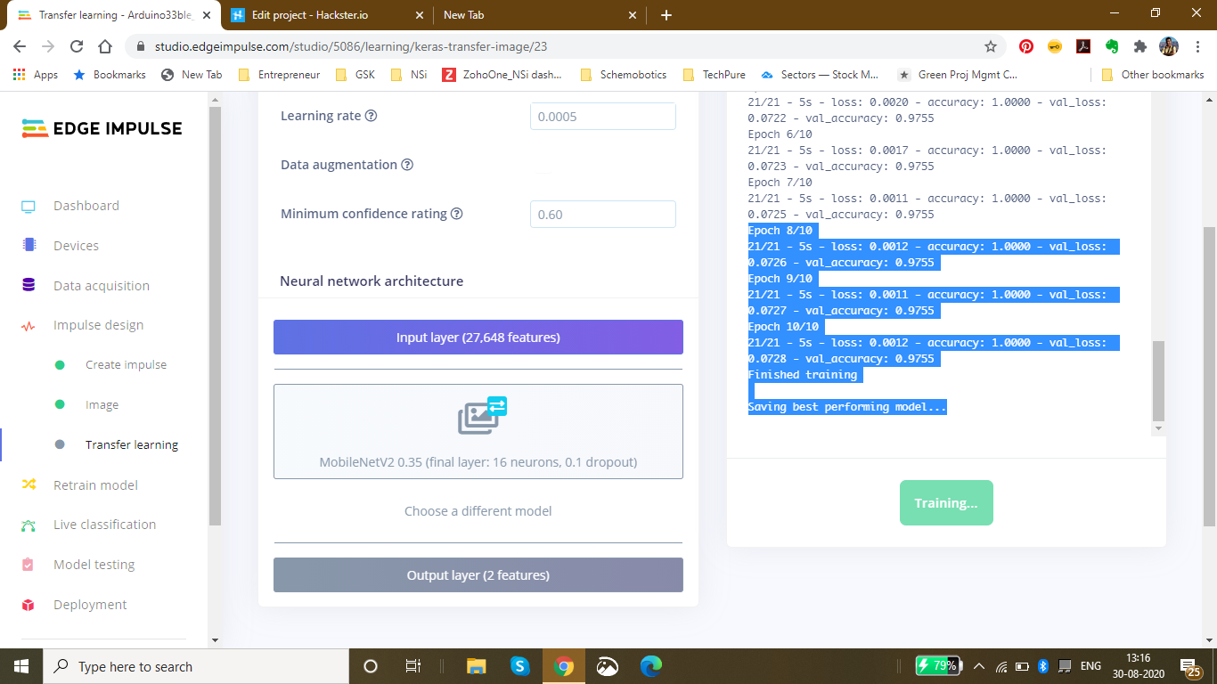
Finally after completing 30 epochs and 10 epochs of best model performance, I got the accuracy heading to 1.00 and the loss nearly 0 which was 0.0011. The following was the ouput during the training process:
Saving best performing model... Converting TensorFlow Lite float32 model... Converting TensorFlow Lite int8 quantized model with float32 input and output...
- Epoch 9/10 21/21 - 5s - loss:0.0011 - accuracy:1.0000 - val_loss:0.0727 - val_accuracy:0.9755
- Epoch 10/10 21/21 - 5s - loss:0.0012 - accuracy:1.0000 - val_loss:0.0728 - val_accuracy:0.9755 Finished training
This was the final output which I received after the training:
The accuracy to be 92.6% and the loss to be 0.19.
<図>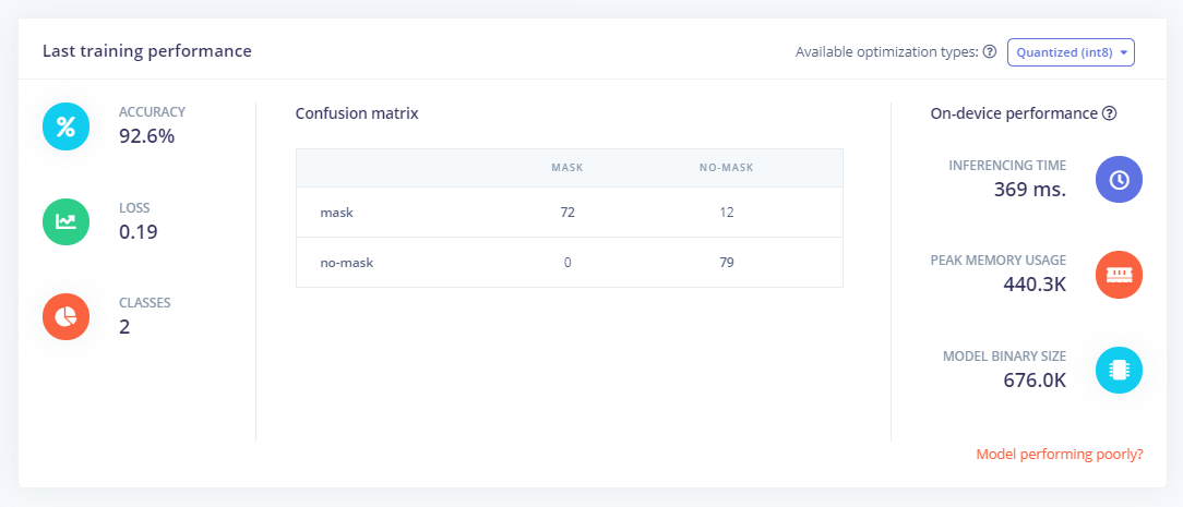
Finally Using the test data, I tested the accuracy and found it to be 98.15%.
<図>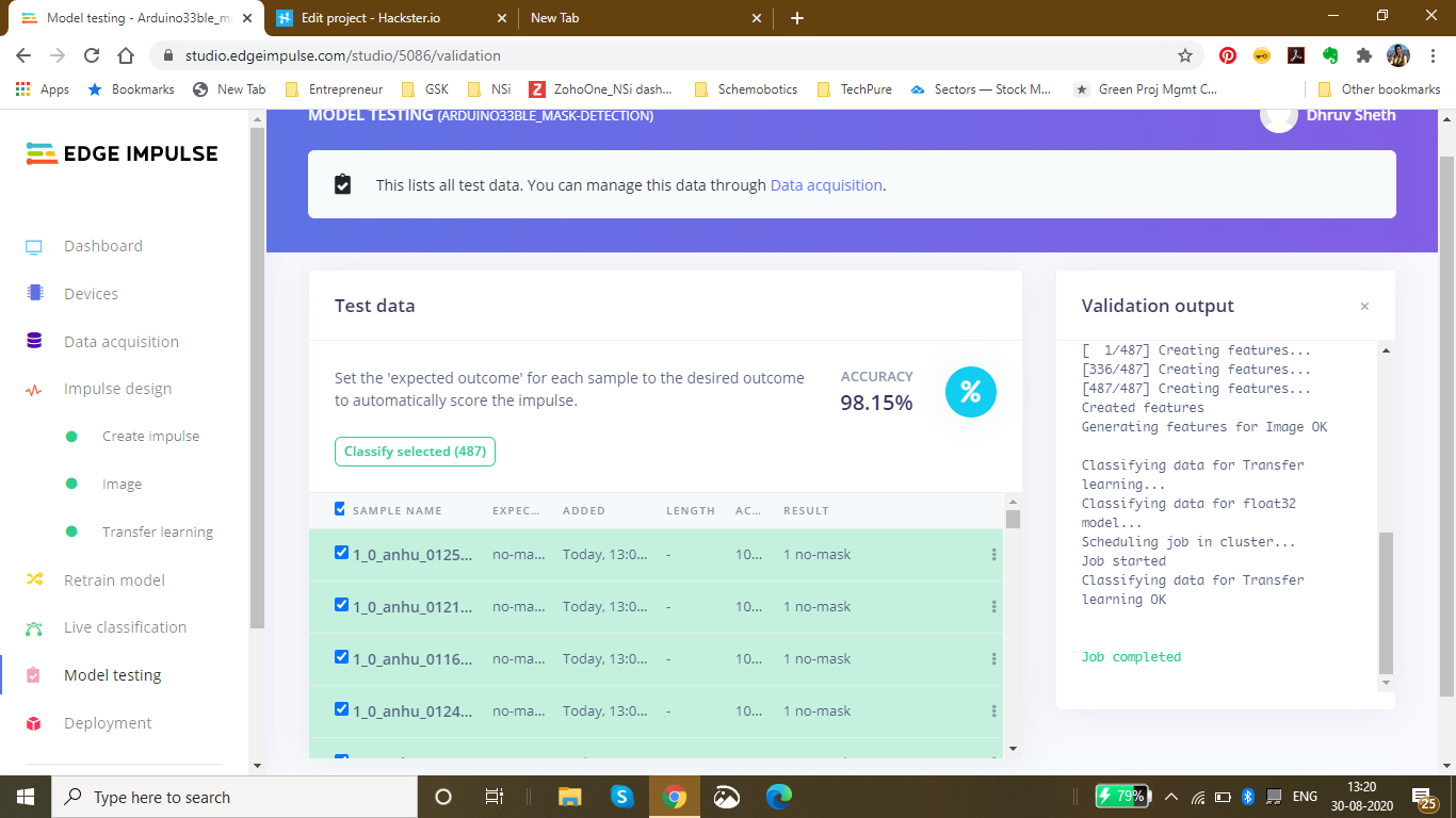
Finally since I had the model ready, I deployed it as an Arduino Library with the firmware to be the Arduino 33 BLE Sense:I got the zip folder of the library ready and started to make changes as per our requirements.
<図>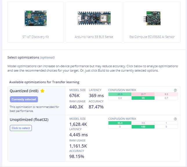
For a last confirmation, I live classified the data to ensure that the data is classified properly. I got the perfect results as expected:
<図>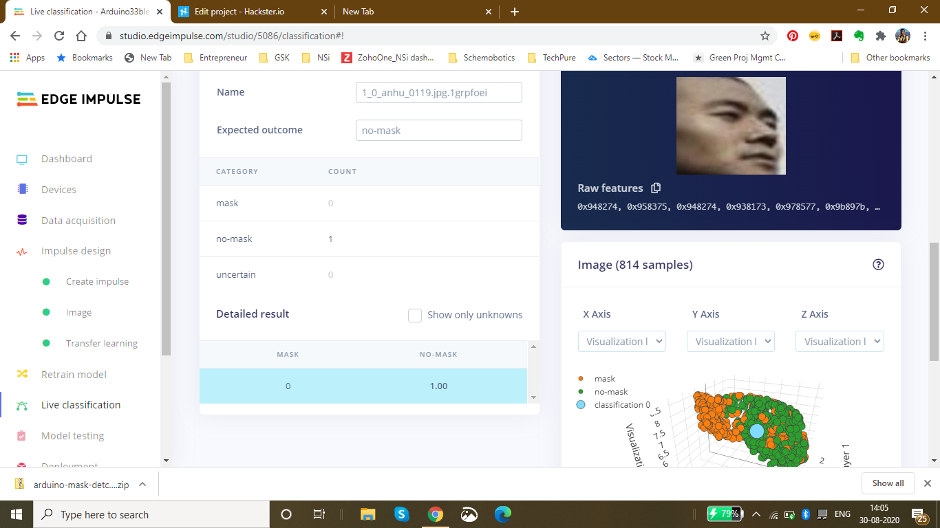
Changing the code as per the output required in the model:
Here is a snippet of the main.ino code of the mask_detection model
<図>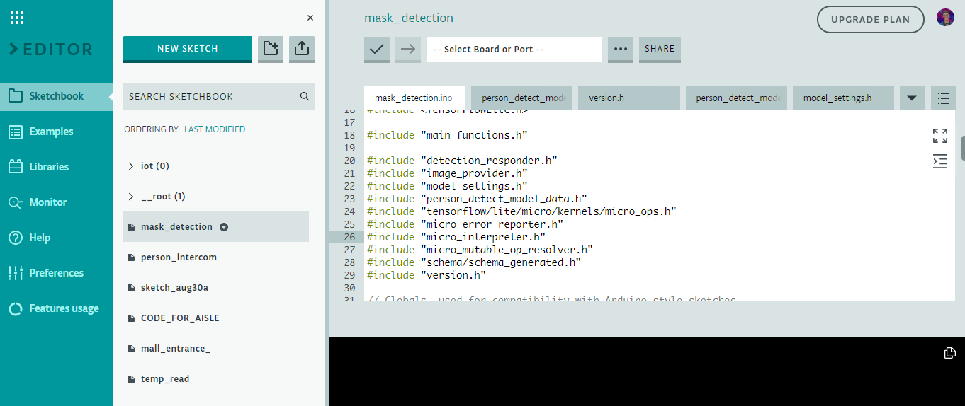
I have defined the arduino libraries required for the functioning of the model and based on the Tensorflow lite framework, I have designed this model.
This is the loop of some of the main functions in the model which are defined in the libraries. The main.ino code centralises these functions and accordingly loops them with a central code.
void loop() {
 // Get image from provider.
 if (kTfLiteOk !=GetImage(error_reporter, kNumCols, kNumRows, kNumChannels,
 input->data.uint8)) {
 TF_LITE_REPORT_ERROR(error_reporter, "Image capture failed.");
 }

 // Run the model on this input and make sure it succeeds.
 if (kTfLiteOk !=interpreter->Invoke()) {
 TF_LITE_REPORT_ERROR(error_reporter, "Invoke failed.");
 }

 TfLiteTensor* output =interpreter->output(0);

 // Process the inference results.
 uint8_t mask_score =output->data.uint8[kmaskIndex];
 uint8_t no_mask_score =output->data.uint8[kno-maskIndex];
 RespondToDetection(error_reporter, mask_score, no_mask_score);
}
The processed data of this model can be viewed here :(This file is relatively large and varies as per the dataset size of the model) Arduino_mask_detect_model_data.h
For providing image, I will be using the Arducam mini 2mp plus for visual data input. A snippet from the image_provider.h file is :
#include "image_provider.h"

/*
 * The sample requires the following third-party libraries to be installed and
 * configured:
 *
 * Arducam
 * -------
 * 1. Download https://github.com/ArduCAM/Arduino and copy its `ArduCAM`
 * subdirectory into `Arduino/libraries`. Commit #e216049 has been tested
 * with this code.
 * 2. Edit `Arduino/libraries/ArduCAM/memorysaver.h` and ensure that
 * "#define OV2640_MINI_2MP_PLUS" is not commented out. Ensure all other
 * defines in the same section are commented out.
 *
 * JPEGDecoder
 * -----------
 * 1. Install "JPEGDecoder" 1.8.0 from the Arduino library manager.
 * 2. Edit "Arduino/Libraries/JPEGDecoder/src/User_Config.h" and comment out
 * "#define LOAD_SD_LIBRARY" and "#define LOAD_SDFAT_LIBRARY".
 */

#if defined(ARDUINO) &&!defined(ARDUINO_ARDUINO_NANO33BLE)
#define ARDUINO_EXCLUDE_CODE
#endif // defined(ARDUINO) &&!defined(ARDUINO_ARDUINO_NANO33BLE)

#ifndef ARDUINO_EXCLUDE_CODE

// Required by Arducam library
#include
#include
#include
// Arducam library
#include
// JPEGDecoder library
#include

// Checks that the Arducam library has been correctly configured
#if !(defined OV2640_MINI_2MP_PLUS)
#error Please select the hardware platform and camera module in the Arduino/libraries/ArduCAM/memorysaver.h
#endif
The Arduino_detection_responder.cpp code performs the inference and delivers the main output required for the code. Here, when a person with a mask is detected, we are opening the gate and if a person with no mask is detected, we are closing the gate.
// Switch on the green LED when a mask is detected,
 // the red when no mask is detected
 if (mask_score> no_mask_score) {
 digitalWrite(LEDG, LOW);
 digitalWrite(LEDR, HIGH);
 servo_8.write(0); // this servo moves to 0degrees in order to open the mall door when a person is detected to ensure no touch entry system
 count++
 } else {
 digitalWrite(LEDG, HIGH);
 digitalWrite(LEDR, LOW);
 servo_8.write(180); // this servo moves to 180degrees when no person is detected
 count2++
 }
The count and count2 are variable integers and increment everytime a mask is detected, or not detected. These counts are then displayed onto the ThingSpeak IoT Dashboard as follows:
The graph displays the mask and no mask count over time. This thingspeak dashboard is setup in the Arduino code as seen here:
#include
#include
WiFiMulti WiFiMulti;
const char* ssid ="Yourssid"; // Your SSID (Name of your WiFi)
const char* password ="Wifipass"; //Your Wifi password
const char* host ="api.thingspeak.com/channels/1118220";
String api_key ="9BRPKINQJJT2WMWP"; // Your API Key provied by thingspeak
The complete code for responder can be viewed here:Arduino_detection_responder.cpp
<図>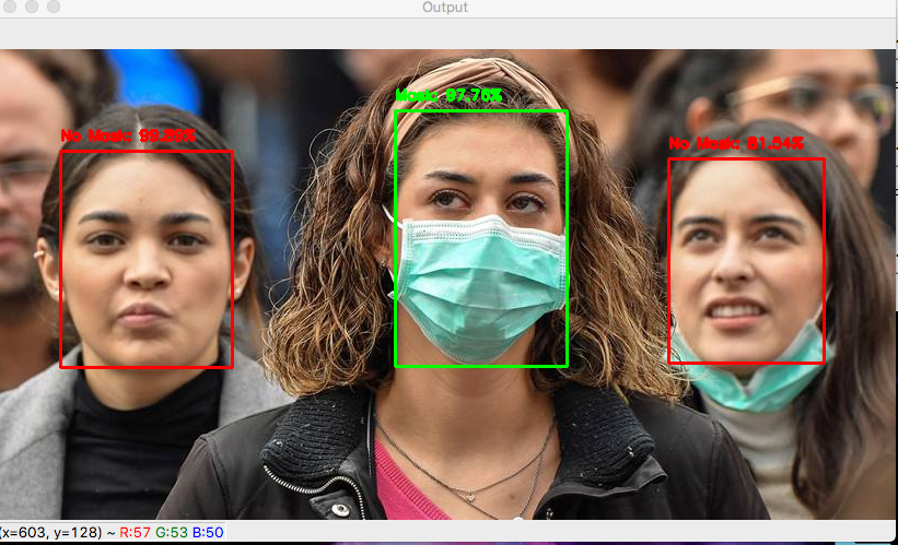
Github Code can be viewed here:Arduino Mask Detetction
The ThingSpeak dashboard can be viewed here - IoT Dashboard
<図>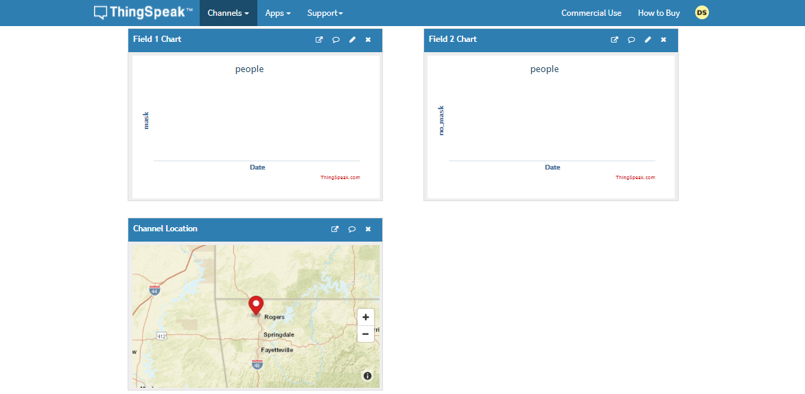
5th project - Person detection in supermarket Aisles and self-sanitisation system:
Just as malls and supermarkets and retail sectors have opened, a risk of contamination of the virus has increased. The main risk that is faced is in supermarkets and stores. The stores could be related to clothes, food and even electronics, the virus could deposit and stay on these surfaces for a long time.
Early data suggests the new coronavirus can live on surfaces for several days
The new coronavirus is, well, new — and there's still much to learn about how easily the virus can spread via contaminated surfaces. But early evidence indicates that the surface survivability of the new coronavirus is similar to that of SARS, a related coronavirus first identified in 2002. Depending on the surface, the virus can live on surfaces for a few hours or up to several days.
The new coronavirus seems to be able to survive the longest on plastic and stainless steel — potentially as long as three days on these surfaces. It can also live on cardboard for up to 24 hours.
Find out what this means for the things you touch throughout the day, including your:
- Clothes
- Food
- Groceries
- Packages
- Electronics
The coronavirus pandemic has breathed new life into a decades-old technique that can zap viruses and bacteria:ultraviolet light.
Hospitals have been using it for years to cut down on the spread of drug-resistant superbugs and to disinfect surgical suites. But there is now interest in using the technology in spaces like schools, office buildings, and restaurants to help reduce coronavirus transmission once public spaces are open again.
The sanitizing effects of UV lights have been seen with other coronaviruses, including the one that causes severe acute respiratory syndrome (SARS). Studies have shown that it can be used against other coronaviruses. One study found at least 15 minutes of UVC exposure inactivated SARS, making it impossible for the virus to replicate. New York's Metropolitan Transit Authority announced the use of UV light on subway cars, buses, technology centers, and offices. The National Academy of Sciences says although there is no concrete evidence for UV’s effectiveness on the virus that causes COVID-19, it has worked on other similar viruses, so it would likely fight this one too.
Abiding by the given information, Malls and Supermarkets have started imposing solutions based on UV sanitisation on manual basis. This consumes a lot of time and also, the data is unavailable. In manual process, one does not know which area has been exposed to human touch more or which are has the highest risk of contamination.
To automate this process and to provide real time spatial analysis of the data collected and the rate of contamination in an area.
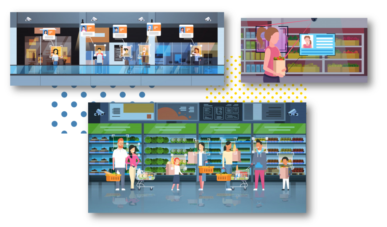
<図> <図>
<図> 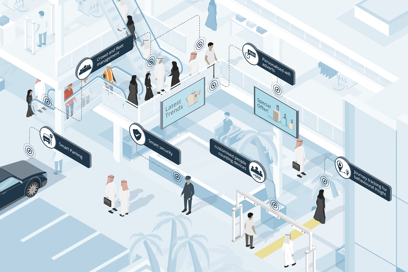
The above images demonstrate the distribution of population across the mall. As it is clearly seen in Figure B, the density near the escalator is comparatively high as compared to the density on the second floor. Manually keeping a track of this continuously changing data in real time and accordingly, sanitising the areas/aisles according to the rate of contamination is not a manual task.
Hence, I decided to make a robust solution for automating this process with the help of TinyML computer Vision &IoT deployed on the Arduino 33 BLE Sense.
The structured framework of this system is as follows:
These models are individually deployed on the Aisles and Areas of the malls and supermarkets close to the Area which has to be sanitised. Since the model utilises person detection Algorithm, the placement of the model is done accordingly.
In this model, for accumulation of Video data, the Arducam mini 2MP Plus is used. The Arducam Mini 2MP Plus continuously gathers visual data and sends this data to the Arduino Nano 33 BLE Sense for processing and classification. The Arduino classifies the data and accordingly processes commands. If a person is detected, the count of people increments by 1 on detection of each person near the Aisle.
A certain threshold for the count of people is set depending upon the rate of contamination based on the object type in that area. The rate of contamination and threshold for food aisle, clothes aisle, sports aisle and Electronic aisle is different.
Accordingly taking into consideration an average threshold, if 25 people are detected, the area is safe. If the count increases to 50, the area is heading towards contamination and the visitors are given an alert. If the count increases to 100, the area is declared contaminated and the people are warned to be careful while touching objects. Finally if the threshold limit is crosses which is 150, the area is autonomously sanitised using UV Light.
The alerts generated are based on LED Colours. Green is an indication for safe, blue is an indication for alert, and Red is an indication for Warning!. These LED based alerts are installed in the respective areas individually.
<図>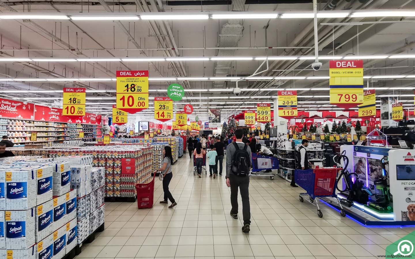
The above image shows the various aisles in the malls where the system can be installed.
<図>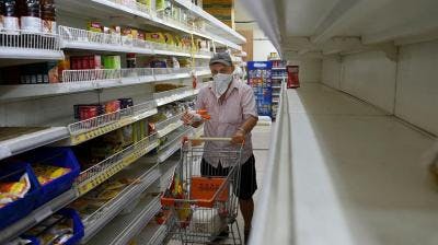
The above image shows the area of installation of Arducam or similar visual data capturing device to cover a wide spectrum of people walking through the aisle.
<図>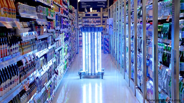 <図>
<図>  <図>
<図> 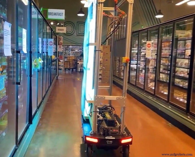
The above Images show a demo implementation of the UV Sanitisation Lights in suitable areas of the aisles. This UV light covers a large spectrum of area that can be sanitised together.
Implementation of the autonomous sanitisation system.
このモデルの設計には、次のソフトウェアが使用されています。
- TensorFlow lite
- ThingSpeak
- ArduinoWebエディター
で この人物検出モデルでは、プロジェクトに適した事前トレーニング済みのTensorFlow人物検出モデルを使用しました。この事前トレーニング済みモデルは3つのクラスで構成されており、そのうち3番目のクラスには未定義のデータセットが含まれています。
"unused"、
"person"、
"notperson"
In our model we have the Arducam Mini 2mp plus to carry out image intake and this image data with a decent rate of fps is sent to the Arduino Nano 33 BLE Sense for processing and and classification. Since the Microcontroller is capable of providing 256kb RAM, we change the image size of each image to a standard 96*96 for processing and classification. The Arduino Tensorflow Lite network consists of a deep learning framework as:
- Depthwise Conv_2D
- Conv_2D
- AVERAGE Pool_2D
- フラットレイヤー
This deep learning framework is used to train the Person detection model.
The following is the most important function defined while processing outputs on the Microcontroller via Arduino_detetction_responder.cpp
// Process the inference results.
 uint8_t person_score =output->data.uint8[kPersonIndex];
 uint8_t no_person_score =output->data.uint8[kNotAPersonIndex];
 RespondToDetection(error_reporter, person_score, no_person_score);
In the following function defining, the person_score , the no_person_score have been defined on the rate of classification of the data.
using these defined functions, I will be using it to give certain outputs on the basis of confidence of the person_score and the no_person_score 。
The detection responder logic of the code works in the following way:
├── Person Detection and sanitisation
├── Arducam mini 2MP Plus
│ ├──Image and Video Data to Arduino
├── Arduino BLE 33 Sense
│ ├── processing and classification of the input data
│ │ ├── If person detected, increment the count by 1
│ │ ├── If no person detected, do nothing
│ │ ├── Send the number of people entered count to to ThingSpeak Dashboard via ESP8266 -01
│ │ | ├── If people count is uptil 25
│ │ │ | ├── Indicate the area to be safe by flashing green light
│ │ | ├── If people count is uptil 50
│ │ │ | ├── Indicate the people to be aware by flashing blue light
│ │ | ├── If people count is uptil 100
│ │ │ | ├── Indicate the area to be contaminated by flashing Red light
│ │ | ├── If people count is between 150 to 175
│ │ │ | ├── Sanitise the area by activating the UV light
│ │ │ | ├── Reset the person count to 0 since the area has been sanitised
│ │ └── ...Repeat the loop
According to the logic used in the model, the Arducam Mini 2MP Plus will continuously capture visual data and send this data to the Arduino Nano 33 BLE sense to process and classify. This model size is 125Kb. Once the image is processed, the Arduino starts to classify the data captured. If a person is detected in the model, the person count increases by 1. This person count is continuously sent to the ThingSpeak dashboard via ESP8266- 01 IoT module. The person count enables the supermarket staff with the data of number of visitors in a particular area at any given point of time. The staff can generate data driven decisions to take action in an area if the visitor count is significantly high.
Proceeding to the output, if the person count is between 1 to 25, the Area is declared safe by flashing the green LED. If the person count is between 26 to 50, the visitors are given an alert by flashing BLUE LED. If the count is between 51 to 100, the area is declared contaminated by flashing the RED LED. When the count surpasses a certain threshold, here taken to be 150, the UV light is turned on until the 165th person passes the area. In this way the Area is sanitised. Similarly the count of people is reset to 0 since the area has been sanitised.
Working of the Firmware:
<図>
This model comprises of the following firmware used:
- Arduino 33 BLE sense - Used to process the data gathered, classifies the data processes, sends the command according to the logic fed.
- Arducam Mini 2mp plus - Continuous Raw data image accumulation from source.
- Adafruit lithium ion charger - Used to deliver charge through the lithium battery
- Lithium ion Battery - power source
- ESP8266 - 01 - Used for sending data to the ThingSpeak dashboard via WiFi network.
- RGB LED - Used for flashing Signals based on the status of contamination
- UV Light - Used to Sanitise the Area ( Since this is a prototype, an LED is displayed. In the actual solution, the UV light consumes a lot of energy hence an external power source needs to be provided. )
Functioning and Working of Logic in Code:
The following are the Libraries included in themain.ino c ode for functioning of the model.
#include

#include "main_functions.h"

#include "detection_responder.h"
#include "image_provider.h"
#include "model_settings.h"
#include "person_detect_model_data.h"
#include "tensorflow/lite/micro/kernels/micro_ops.h"
#include "tensorflow/lite/micro/micro_error_reporter.h"
#include "tensorflow/lite/micro/micro_interpreter.h"
#include "tensorflow/lite/micro/micro_mutable_op_resolver.h"
#include "tensorflow/lite/schema/schema_generated.h"
#include "tensorflow/lite/version.h"
The main outcome of the model is dependent on the logic fed in detection_responder.cpp. This snippet shows the generalized threshold of the contamination of the object set to a count of 101.
void RespondToDetection(tflite::ErrorReporter* error_reporter,
uint8_t person_score, uint8_t no_person_score) {
static bool is_initialized =false;
if (!is_initialized) {
// Pins for the built-in RGB LEDs on the Arduino Nano 33 BLE Sense
pinMode(LEDR, OUTPUT);
pinMode(LEDG, OUTPUT);
pinMode(LEDB, OUTPUT);
is_initialized =true;
}
// Note:The RGB LEDs on the Arduino Nano 33 BLE
// Sense are on when the pin is LOW, off when HIGH.
// Switch the person/not person LEDs off
digitalWrite(LEDG, HIGH);
digitalWrite(LEDR, HIGH);
// Flash the blue LED after every inference.
digitalWrite(LEDB, LOW);
delay(100);
digitalWrite(LEDB, HIGH);
// Switch on the green LED when a person is detected,
// the red when no person is detected
if (person_score> no_person_score) {
digitalWrite(LEDG, LOW);
digitalWrite(LEDR, HIGH);
count++
} else {
digitalWrite(LEDG, HIGH);
digitalWrite(LEDR, LOW);
}
TF_LITE_REPORT_ERROR(error_reporter, "Person score:%d No person score:%d",
person_score, no_person_score);
}
if (constrain(count, 1, 50)) {
digitalWrite(LEDGREEN, LOW); // This is a green LED which means area is not contaminated yet
}
if (constrain(count, 51, 75)) {
digitalWrite(LEDBLUE, LOW); // This is a b led so that people are alert that more than 50 people
}
if (constrain(count, 76,100)) {
digitalWrite(LEDRED, LOW); // This is a red LED which warns people that this area is contaminated and one should take care while touching objects
}
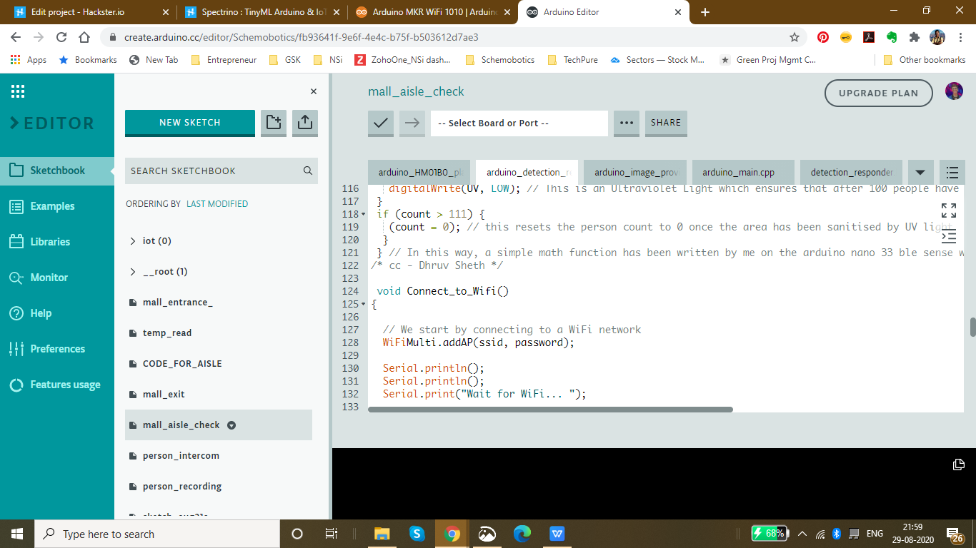
if (constrain(count, 101, 110)) {
digitalWrite(UV, LOW); // This is an Ultraviolet Light which ensures that after 100 people have touched the aisle objects, it sanitises the area with UV light
}
if (count> 111) {
(count =0); // this resets the person count to 0 once the area has been sanitised by UV light
}
} // In this way, a simple math function has been written by me on the arduino nano 33 ble sense which alerts people and sanitizes areas
/* cc - Dhruv Sheth */ The below snippet is carried out by the ESP8266 -01 module to send data to the allocated field in the ThingSpeak Dashboard:
void Send_Data()
{


 // Use WiFiClient class to create TCP connections
 WiFiClient client;

 const int httpPort =80;

 if (!client.connect(host, httpPort)) {
 Serial.println("connection failed");
 return;
 }
 else
 {
 String data_to_send =api_key;
 data_to_send +="&field1=";
 data_to_send +=String(count);
 data_to_send +="\r\n\";

 client.print("POST /update HTTP/1.1\n");
 client.print("Host:api.thingspeak.com\n");
 client.print("Connection:close\n");
 client.print("X-THINGSPEAKAPIKEY:" + api_key + "\n");
 client.print("Content-Type:application/x-www-form-urlencoded\n");
 client.print("Content-Length:");
 client.print(data_to_send.length());
 client.print("\n\n");
 client.print(data_to_send);

 delay(10); // reduced delay to perform real time data collection
 }

 client.stop();

} 
The threshold for each Aisle inside the mall is set to be different according to the rate of contamination of the model. This data can be altered according to the need of the malls or supermarkets. These thresholds can also be altered according to the time trends and the population density in that area.
Threshold set for the Clothes Aisle:
if (constrain(count, 1, 50)) {
 digitalWrite(LEDGREEN, LOW); // This is a green LED which means area is not contaminated yet
}
 if (constrain(count, 51, 75)) {
 digitalWrite(LEDBLUE, LOW); // This is a b led so that people are alert that more than 50 people
}
 if (constrain(count, 76,100)) {
 digitalWrite(LEDRED, LOW); // This is a red LED which warns people that this area is contaminated and one should take care while touching objects
}
 if (constrain(count, 101, 110)) {
 digitalWrite(UV, LOW); // This is an Ultraviolet Light which ensures that after 100 people have touched the aisle objects, it sanitises the area with UV light
 }
 if (count> 111) {
 (count =0); // this resets the person count to 0 once the area has been sanitised by UV light
 }
Threshold for the Electronics Aisle, since the virus stays on these surfaces comparatively less, we have set a higher threshold in this case.
if (constrain(count, 1, 75)) {
 digitalWrite(LEDGREEN, LOW); // This is a green LED which means area is not contaminated yet
}
 if (constrain(count, 76, 180)) {
 digitalWrite(LEDBLUE, LOW); // This is a b led so that people are alert that more than 50 people
}
 if (constrain(count, 181,225)) {
 digitalWrite(LEDRED, LOW); // This is a red LED which warns people that this area is contaminated and one should take care while touching objects
}
 if (constrain(count, 225, 240)) {
 digitalWrite(UV, LOW); // This is an Ultraviolet Light which ensures that after 100 people have touched the aisle objects, it sanitises the area with UV light
 }
 if (count> 111) {
 (count =0); // this resets the person count to 0 once the area has been sanitised by UV light
 }
Threshold set for Food and eatables:, Since these are consumptives, they face a higher risk of contamination. Hence, a lower threshold is set in this case.
if (constrain(count, 1, 25)) {
 digitalWrite(LEDGREEN, LOW); // This is a green LED which means area is not contaminated yet
}
 if (constrain(count, 25, 50)) {
 digitalWrite(LEDBLUE, LOW); // This is a b led so that people are alert that more than 50 people
}
 if (constrain(count, 51,75)) {
 digitalWrite(LEDRED, LOW); // This is a red LED which warns people that this area is contaminated and one should take care while touching objects
}
 if (constrain(count, 76, 90)) {
 digitalWrite(UV, LOW); // This is an Ultraviolet Light which ensures that after 100 people have touched the aisle objects, it sanitises the area with UV light
 }
 if (count> 91) {
 (count =0); // this resets the person count to 0 once the area has been sanitised by UV light
 }
Setting up the Thingspeak IoT Dashboard:
<図>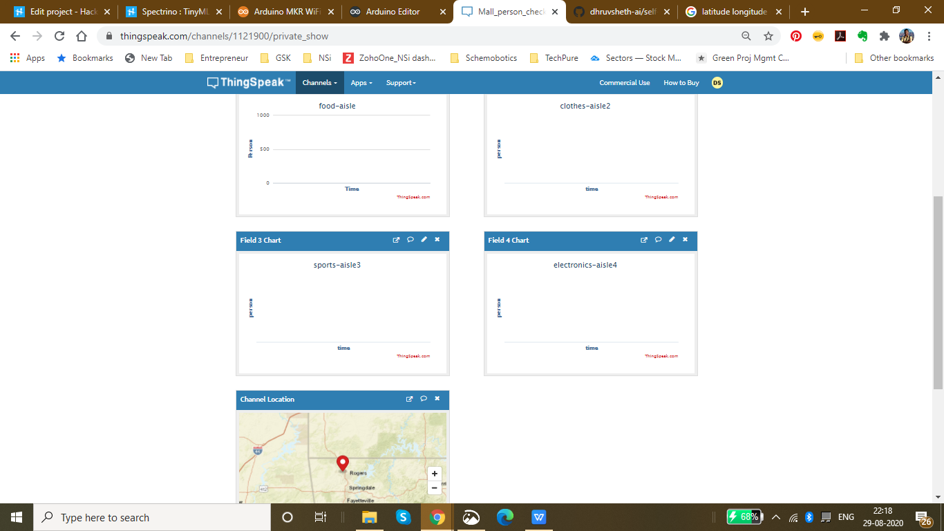 <図>
<図> 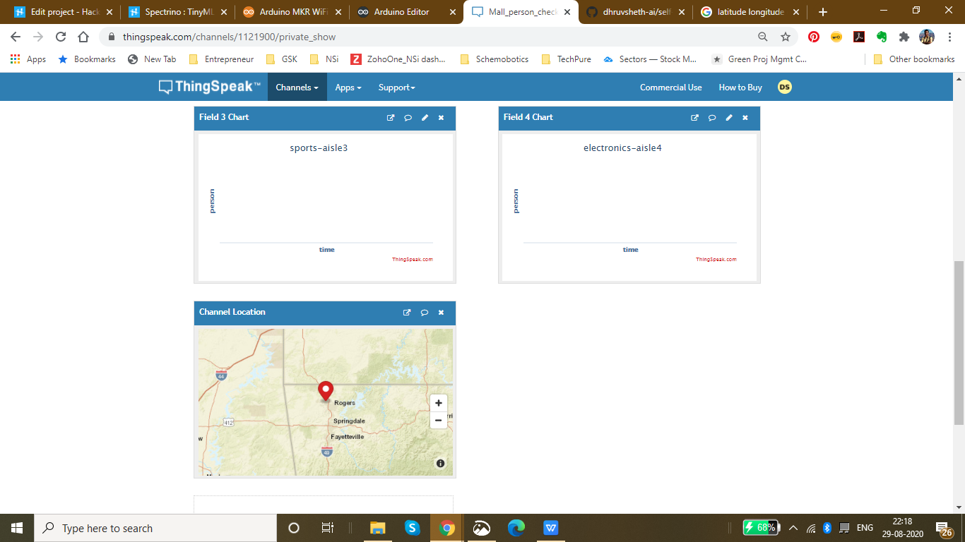
On the thingspeak dashboard, there are 4 fields which have been added for the 4 aisles that have been set up namely:
- Food-aisle
- Sports-aisle
- Clothes-aisle
- Electronics-aisle
The co-ordinate locations of the mall can be seen in the channel visualization which can be cumulatively displayed on a single dashboard through which the data for each supermarket and mall in a locality can be accessed.
The IoT Dashboard can be viewed here:IoT Dashboard
The fields and channels of aisles can be all displayed together on a single Thingspeak IoT Dashboard.
<図>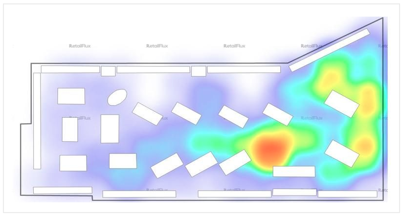
The above image shows a density plot of the density population in a given region in the store of a mall.
Currently I have been using the ThingSpeak Dashboard to plot the data in a graphical format. But, using the same data and Tableau visualizations, it is possible to plot the given data on the floor plot map of the Supermarket.
This data will be easily accessible to other visitors entering the supermarket and will be able to interpret data driven decisions like visiting the store which has a low population density.
Now a question might arise that what makes the product unique:
Currently, the UV sanitisation system is implemented on manual basis and hence the sanitisation system is carried out manually monitoring these areas. Autonomous UV robots are deployed in malls to gather plot data of mall and map these areas, hence autonomously sanitising these areas. These solutions are not capable of sanitising each aisle and area in the mall along with the flowing population of the people in the mall. The sanitisation is only limited to sanitising the lower part of these aisles and hence the upper parts are left unsanitised. These solutions are also comparatively expensive and they are not capable of continuous data monitoring and sanitisation respective to the rate of contamination. This means that they are unable to monitor the number of people who have passes through a certain area or aisle and hence are unable to sanitise areas according to their contamination.
Go to Market and Viability:
- Malls and Supermarkets can use this to identify The count of people in and density of people in a certain area in a store and impose self sanitisation process within the malls.
- Implement Strategies using this data to ensure Safety and Compliance with efficient Population Density monitoring algorithms.
- Decrease Labour and automate Sanitisation process.
- Offer Dashboard to the visitors to monitor the density of people at a certain area inside the mall and accordingly the visitors can have a view of the store with lowest density population and make decisions based on this data. The visitors can also have a view of the timely trends of sanitisation by viewing the abrupt change of person density graph in an area when sanitisation is conducted. ( Since, each time sanitisation in an area takes place, the person count is reset to 0 because the place is sanitised)
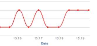
- This product can be used to ensure the visitors that the mall is a safe place and hence, can increase the sales and visits following Government guidelines
- Companies offering Ai and IoT based solutions can invest for mass production and distribution.
- The more the supermarkets using this product, the more the access to data to the government and more the choice to customers to select the preferable safest place in their locality and which store is continuously sanitised to be up to mark in terms of safety. This will lead to a wide range of options of supermarkets in the locality comparing the queue time and safety.
- Comparatively affordable solution as compared to autonomous UV Robot system and highly scalable in terms of data and services with IoT Dashboard provided.
- Utilize real-time CCTV footage to impose autonomous sanitisation system through person detection in terms of timely trends and spatial analysis of person density in the mall.
- Enable Stores to make better, data-driven decisions that ensure your safety and efficient Queues based on autonomous queuing system.
Github Link :https://github.com/dhruvsheth-ai/self-sanitisation-person-detection
PROJECT VIDEO:
Thank you for viewing my project!
コード
- Elevator Automation using "up" - "down" speech command
Elevator Automation using "up" - "down" speech commandArduino
The below is a .zip file of the Arduino LibraryNo preview (download only).
Mall Aisle Self Sanitization with Person Detection System
https://github.com/dhruvsheth-ai/self-sanitisation-person-detetctionTemperature monitoring system based on IoT
https://github.com/dhruvsheth-ai/temperature-arduino-iotMask Detection Algorithm
https://github.com/dhruvsheth-ai/ble-mask-detection-optimisedAutonomous Person Intercom based on TinyML
https://github.com/dhruvsheth-ai/person-autonomous-intercomElevator Automation using TinyML
https://github.com/dhruvsheth-ai/elevator-Automation-ARDUINOMall Entrance Person Detection and Queuing System
Queuing System based on TinyML person detection on Mall Entrance and exit connected via IoT Thingspeak dashboard for Live data monitoringhttps://github.com/dhruvsheth-ai/Person-queuing-system-arduino33 回路図
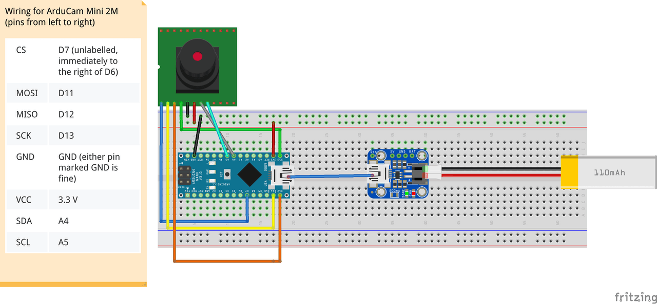
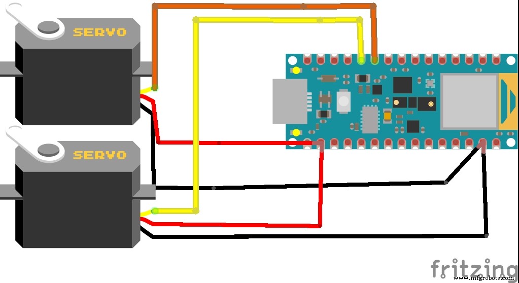
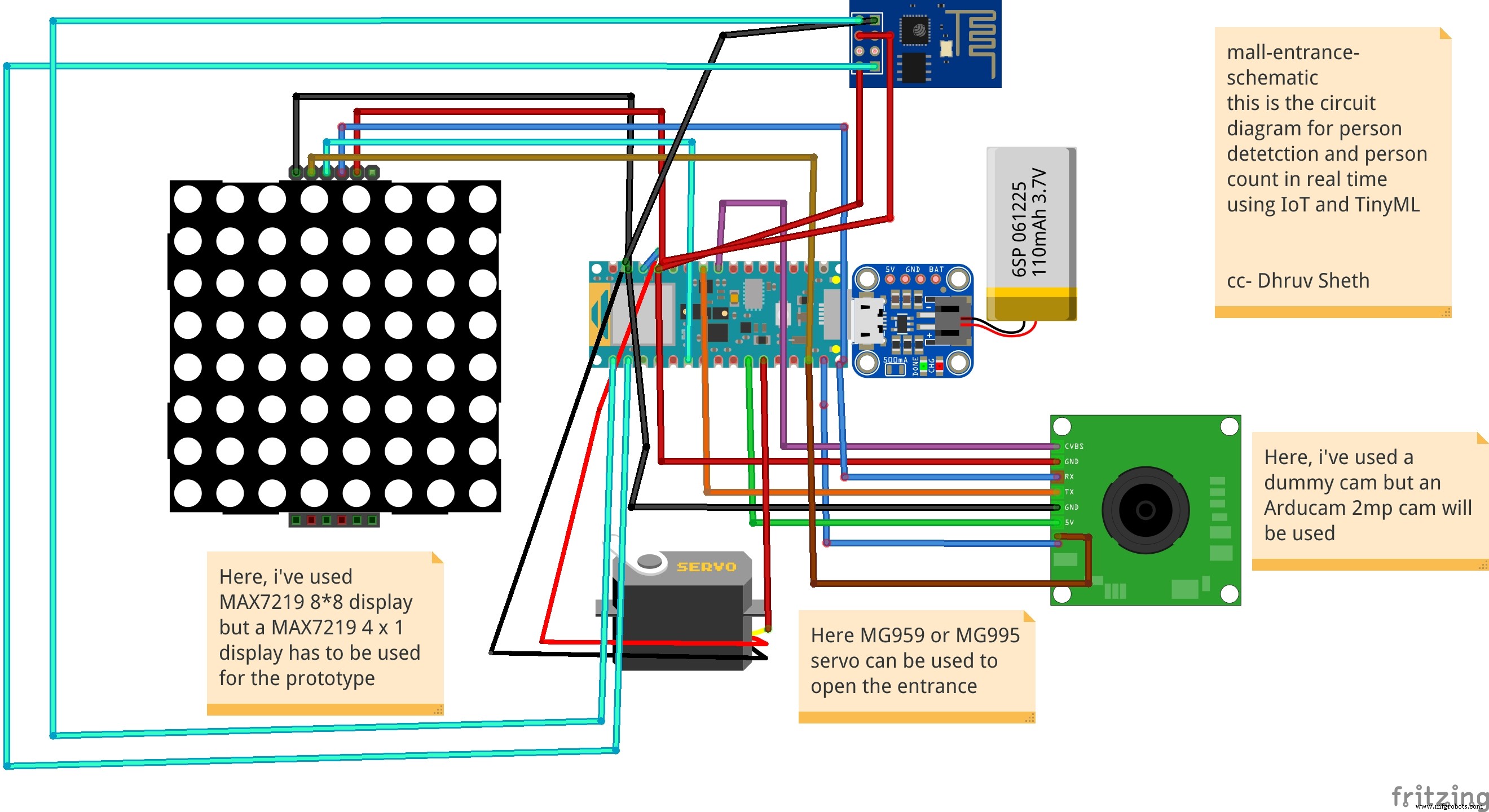 This is the Schematic for the Mall Aisle Person detection and self sanitization system that transfers data to ThingSpeak IoT Dashboard
 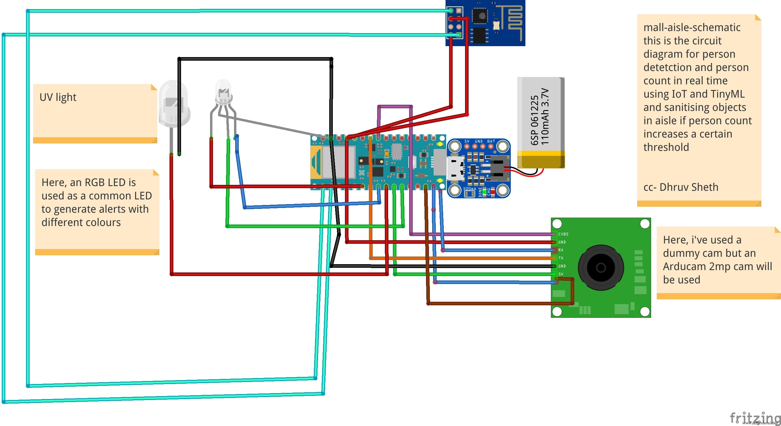 Detects a person present at the door and rings the bell and displays "person" on the LED Matrix as an alternative
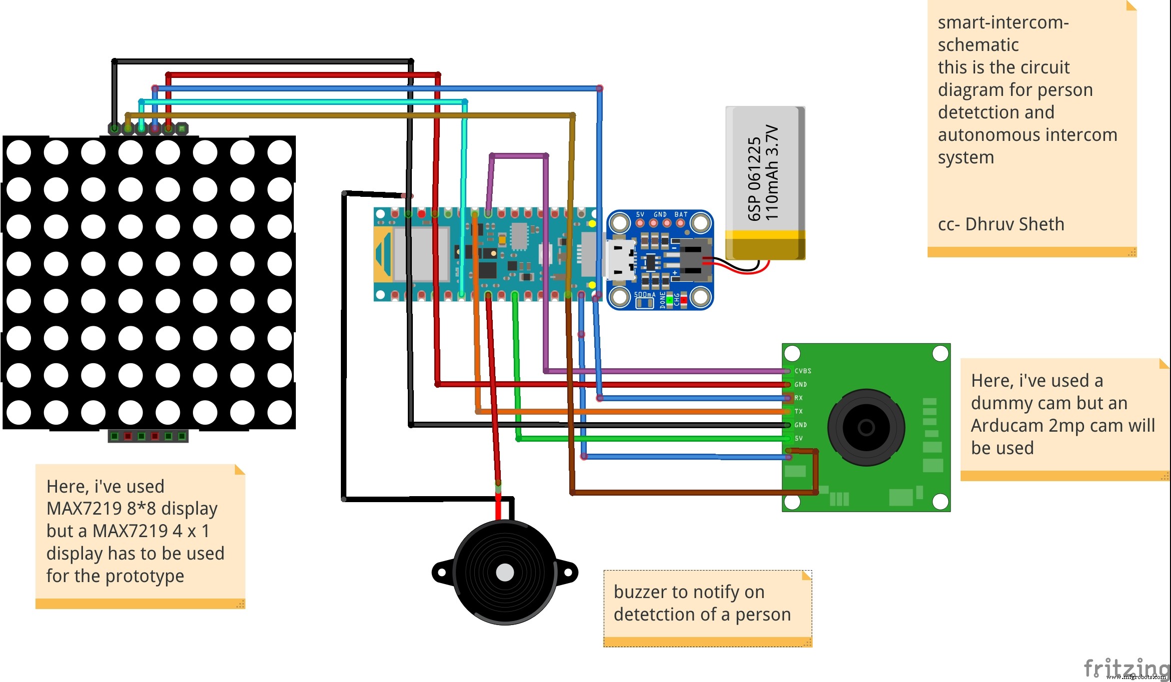
製造プロセス