


3D プリンティングの種類:3D プリンティング テクノロジーの 7 つの主要カテゴリ
「3D プリンティング」と聞くと、ほとんどの人はプラスチック部品を製造する小型のデスクトップ機械を想像します。しかし、舞台裏ではさらに多くのことが起こっています。私たちが 3D プリントと呼んでいるものは、実際には、デジタル デザインからオブジェクトをレイヤーごとに構築するさまざまなテクノロジーのグループです。
固体ブロックから材料を削り出す従来の製造とは異なり、3D プリンターは必要なものだけを追加します。
ISO/ASTM 52900-15 規格によれば、3D プリンティングは、バット光重合、材料ジェッティング、バインダージェッティング、パウダーベッドフュージョン、材料押出、指向性エネルギー蒸着、シートラミネートの 7 つのカテゴリに分類されます。これらはそれぞれ異なるアプローチを使用しており、扱う材料、予算、パーツの複雑さに応じて、それぞれに独自の長所があります。
現在最も先進的な 3D プリンティング手法の一部は、1980 年代にまで遡ります。光造形 (SLA) は 1986 年に特許を取得し、それ以来、FDM、SLS、MJF などの大きな進歩が見られ、速度、詳細、材料範囲、コスト効率など、それぞれが異なる目標に向けて設計されています。
現在では、200 ドル未満のデスクトップ マシンや、100 万ドルを超える産業グレードのシステムが見つかります。 PLA や ABS から金属粉末、セラミック、フォトポリマー樹脂に至るまで、3D プリント業界は愛好家と製造エンジニアの両方にとって重要なツールに成長しました。
この記事では、主要な 3D プリントの各タイプを分類し、それらがどのように機能するかを調べ、始めたばかりの場合でも、生産をスケールアップしている場合でも、どれがニーズに最適であるかを判断できるようにします。
材料の押し出し
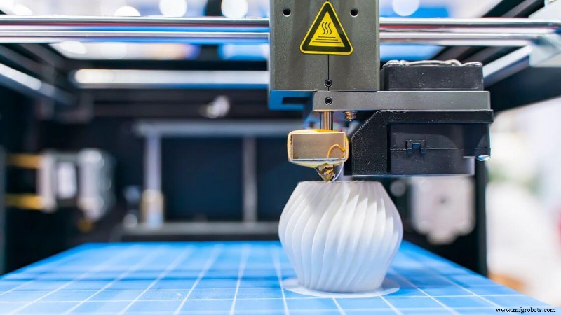 材料押し出しとは、造形材料がノズルから押し出され、層ごとに配置されて 3 次元部品を形成する一連の 3D プリント プロセスを指します。
材料 (通常は熱可塑性プラスチック) は半液体になるまで加熱され、コンピューター支援設計ファイルによってガイドされた制御されたパスで押し出されます。各層は冷えるにつれて前の層と融合し、固体構造を形成します。
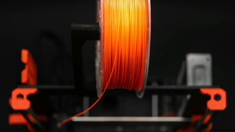
これは、最も一般的で利用しやすいタイプの 3D プリント方法の 1 つです。スプールされたフィラメントを使用するデスクトップ 3D プリンタでよく見られますが、このカテゴリには、ペレット、コンクリート、またはペーストを押し出す大容量マシンも含まれます。
小型コンポーネントを製造する場合でも、大規模なプロトタイプを製造する場合でも、材料押出成形により、設計と製造量に大きな柔軟性がもたらされます。
サポートされている 3D プリント素材の範囲は多岐にわたります。 PLA、ABS、PETG などの標準的な熱可塑性プラスチックが一般的ですが、より高度なセットアップでは、炭素繊維複合材料、耐熱性ポリマー、または金属充填フィラメントを処理できます。
一部の機械は建築や食品のモデリングにも使用されています。
寸法精度は通常、±0.5 mm 程度ですが、機器、材料、環境制御によって異なります。オーバーハングのあるオブジェクトには、印刷中の崩壊を防ぐためのサポート構造が必要になることがよくあります。表面仕上げを改善し、サポートを除去するために後処理が必要になる場合があります。
材料の押出成形は、特に選択的レーザー焼結やステレオリソグラフィーなどのより複雑な技術と比較した場合、コスト効率の点で依然としてプロトタイピングの主要な選択肢となっています。また、このカテゴリの実装として広く使用されている溶融堆積モデリングの基礎としても機能します。
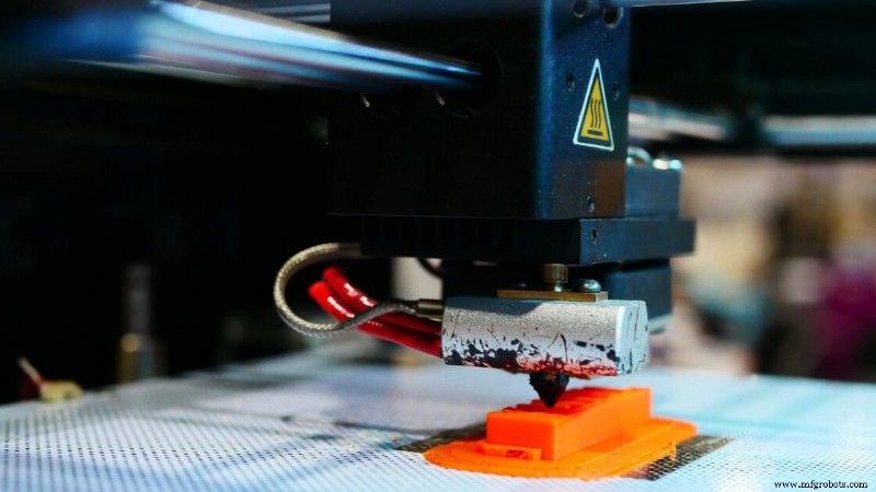
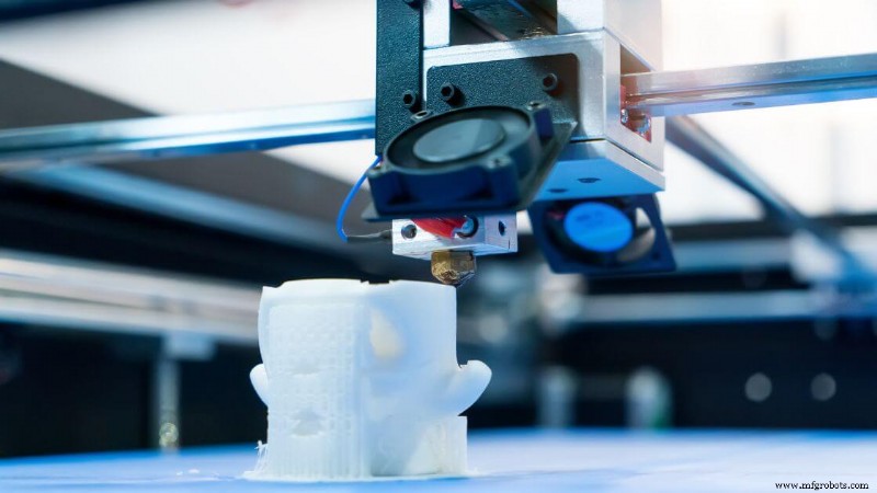
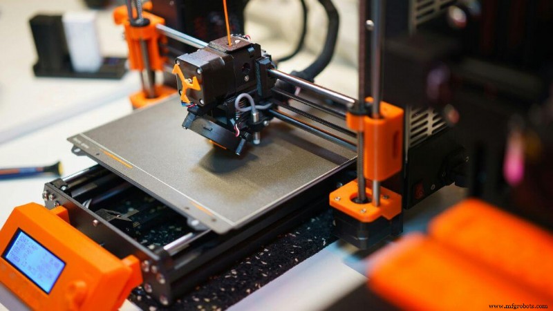
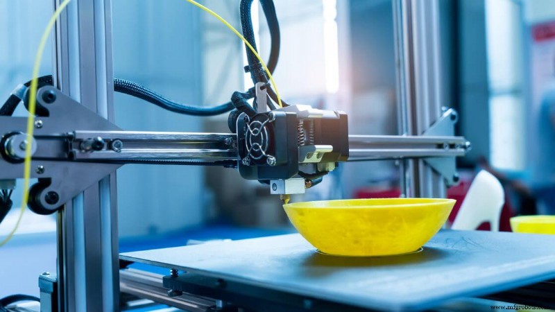
溶融堆積モデリング (FDM) または溶融フィラメント製造 (FFF)
溶融フィラメント製造としても知られる溶融堆積モデリングは、熱可塑性フィラメントを加熱されたプリント ヘッドに供給する材料押出成形の一種です。材料が溶けてノズルから押し出され、ビルド プレート上で冷えて固まるにつれて 3D オブジェクトの各層が形成されます。
通常、PLA、ABS、PETG、TPU などの素材を使用します。より高度なオプションには、ポリカーボネート、ULTEM、カーボンファイバーまたは金属粉末を充填したフィラメントなどがあります。これらのフィラメントは、パーツの機能要件に応じて、さまざまな機械的特性を提供できます。
このプロセスは、ラピッド プロトタイピング、教育モデル、消費者製品テスト、治具や治具などの製造補助具などのアプリケーションに最適です。
FDM 3D プリントは、量産前に部品の形状やアセンブリの適合性を評価する必要がある製品開発ワークフローでも一般的です。
一般的な精度の範囲は±0.5 mm 程度で、層の解像度は通常 50 ~ 300 ミクロンの範囲になります。印刷速度は材料や部品の複雑さによって異なりますが、標準速度は 40 ~ 100 mm/s です。
長所:
- 低コスト:エントリーレベルのプリンタとフィラメントは、手頃な価格で広く入手可能です。
- 素材の多様性:さまざまな強度、色、仕上げを備えたプラスチックの幅広い選択肢
- 使いやすさ:シンプルなソフトウェア ワークフローにより、初心者にも専門家にも同様に親しみやすくなります。
- スケーラビリティ:デスクトップ マシンから大規模なビルドボリュームを伴う産業規模のシステムまで利用可能
短所:
- 可視のレイヤー ライン:後処理を適用しない限り、パーツにはレイヤー間の隆起が表示されることがよくあります。
- 層間の結合が弱い:部品の向きによっては機械的特性が不安定になる可能性があります。
- サポート要件:オーバーハングやブリッジには追加の材料が必要な場合があり、後で除去する必要があります。
- 精度が低い:樹脂 3D プリントやパウダー ベッド フュージョンと比較して、FDM は細部の処理に苦労する可能性があります。
3D バイオプリンティング
 3D バイオプリンティングは、バイオ インク (通常はハイドロゲルに懸濁された生きた細胞から作られます) を使用して、組織のような構造を層ごとに作成する特殊な形式の材料押出です。
熱可塑性プラスチックや金属粉末に依存する従来の 3D プリント方法とは異なり、このプロセスでは細胞の生存率と生体材料の適合性が優先されます。
機能的な生物学的幾何学的形状を形成しながら、生きているコンポーネントへの損傷を避けるために、押し出しは正確かつ穏やかでなければなりません。
このプロセスで見つかる材料には、アルギン酸塩、コラーゲン、ゼラチン、フィブリンなどの生分解性ポリマーが含まれます。
これらは細胞の成長と配置をサポートする足場として機能します。構造は実際の組織を模倣する必要があるため、これらの材料は適合性、柔軟性、血管新生をサポートする能力を考慮して選択されます。
アプリケーションは急速に進歩しています。 3D バイオプリンティングは、臓器オンチップ デバイス、組織足場、再生医療モデル、さらには皮膚や軟骨の初期段階のバイオファブリケーションの研究にも使用されています。これらは単なるコンセプト モデルではなく、将来の埋め込み型ソリューションに向けた実践的なステップです。
寸法精度は、プリンターのキャリブレーションとバイオインクの粘度に応じて、100 ~ 200 ミクロンまたはそれ以上に達する可能性があります。ただし、パフォーマンスは湿度、プリントヘッドの制御、無菌性などの環境要因によって異なります。
印刷速度は、セル密度、ノズル サイズ、およびヒドロゲルの流量によって異なります。通常、プリントはポリマー押し出しよりも時間がかかります。これは、セルの健全性を維持することが速度よりも重要であるためです。
長所:
- 組織工学の可能性:機能臓器と再生療法への道を提供する
- カスタマイズ性:薬物検査や患者固有のインプラントに合わせた構造のカスタマイズ
- レイヤーごとの制御:さまざまな種類のセルの空間配置が可能になります。
短所:
- 非常に複雑:温度、無菌性、バイオインクの一貫性を厳密に制御する必要があります。
- 寿命が限られている:プリントされたコンストラクトは多くの場合、すぐに培養または調整する必要があります。
- 規制のハードル:臨床使用には広範なテストとコンプライアンスの手順が必要です。
建設 3D プリント
建設 3D プリンティングは、自動押出システム (通常はロボット アームやガントリーに取り付けられたノズル) を使用して、コンクリートなどの建設グレードの材料を層状に堆積する大規模な積層造形方法です。
従来の方法とは異なり、3D プリント技術を使用してデジタル モデルから直接構築するため、標準的な型や型枠を使用せずに壁、構造シェル、さらには建物全体を層ごとに製造できます。
通常、これらのシステムでは、セメント混合物、急結コンクリート、ジオポリマー化合物、特殊モルタルなどの材料が使用されています。
ベース材料の選択は、厳密な流動性と硬化要件を満たしている必要があり、構造の完全性を維持しながら、新しい各パーツ層が以前のパーツ層と良好に接着するようにする必要があります。
このアプローチは、持続可能かつ迅速かつ低コストの建設を目指すプロジェクトにおいて世界的に注目を集めています。低所得者向け住宅から緊急避難所、芸術的な建築に至るまで、応用範囲は拡大しています。
まだ発展途上ですが、3D プリンターがわずか数日で家全体や主要な構造部品を作成し、従来の建設スケジュールよりも数週間を節約したという実際の例がいくつか見つかります。
精度は通常、プリンターのビルド プラットフォーム サイズ、ノズルの精度、環境要因に応じて ±5 mm ~ ±10 mm の範囲になります。印刷速度はさまざまですが、直線や繰り返しの形状の場合は手作業よりも速いことがよくあります。レイヤーの解像度は 10 mm ~ 30 mm と粗くなる傾向がありますが、仕上げ技術を使用して改善できます。
長所:
- 特に反復的なタスクにおいて労働要件を削減する
- 特定のジオメトリのビルド時間を大幅に短縮する
- 蒸着モデリング中の材料の無駄を最小限に抑える
- 従来の方法では実現できなかった、新しい有機的な建築形式を可能にする
短所:
- 大規模な機器が必要となり、機動性とセットアップの容易さが制限される
- 材料は流動性と迅速な硬化を実現するために正確に設計されている必要があります
- コードのコンプライアンスと検査基準は依然として進化中
- 表面仕上げとパーツの形状は、印刷後に手動で調整する必要がある場合があります
バット光重合
バット光重合は、光を使用して液体樹脂の層を選択的に硬化させて固体部品を形成する 3D プリント プロセスです。まず、特定の波長の光に反応するフォトポリマー樹脂 (通常はアクリルベース) をバットに満たします。
レーザー、デジタル ライト プロジェクター、または LCD スクリーンにより、この硬化プロセスが高精度で行われます。各フォトポリマー層が硬化するにつれて、ビルド プラットフォームが徐々に上昇または下降して、次の層が形成できるようになります。このシーケンスは、オブジェクト全体が完了するまで繰り返されます。
この方法の特徴は、非常に細かいディテールと非常に滑らかな表面仕上げを実現できることです。そのため、歯型、複雑な宝飾品、小型医療部品など、精度が重要となる用途に好まれています。
精密に調整された機械では、寸法精度が ±0.1 mm 以内、またはそれ以上になる可能性があり、露光と樹脂の流動挙動が制御されるため、パーツの形状は一貫したままになります。
このプロセスは、SLA、DLP、LCD などの複数のフォーマットでも見られます。それぞれのフォーマットでは、わずかに異なる光源が使用されますが、光重合という同じ一般原理に基づいて動作します。
これらの機械で使用される樹脂にはさまざまな配合があり、靭性を重視して最適化されたものもあれば、柔軟性、透明性、または耐熱性を重視して最適化されたものもあります。一部は生体適合性があり、医療プロトタイピングや外科用ガイドでの使用を可能にします。
ただし、サポート構造は特定のオーバーハングまたはブリッジ フィーチャに必要であり、印刷後に手動で削除する必要があることに注意してください。通常、UV 光による後硬化は、機械的特性を改善し、残留粘着性のないきれいな表面を確保するために不可欠です。
光造形 (SLA)
 光造形 (SLA) は、商業的に成功した最初の 3D プリント プロセスであり、現在でも最も正確な 3D プリント プロセスの 1 つです。 SLA システムでは、UV レーザーが感光性樹脂の層を一度に 1 層ずつトレースして固化させます。
その後、造形プラットフォームが徐々に移動し、後続の各パーツ層が最後のパーツ層の上で硬化できるようになります。これにより、優れた表面品質を備えたシームレスな構造が作成されます。
SLA を際立たせているのは、その幅広い特殊樹脂です。プロトタイプ用の標準樹脂、耐熱用の高温バージョン、弾性部品用の柔軟なオプション、さらにはジュエリーやインベストメント鋳造で使用される鋳造可能なフォーミュラも見つかります。一部の生体適合性樹脂は、歯科用途や医療機器に使用されています。
一般的な SLA プリンタは、部品の形状や印刷設定に応じて、25 ミクロンもの微細な層解像度と ±0.1 mm 近い寸法公差を実現します。印刷速度は最大の利点ではありませんが、結果は一貫して高品質で細部まで精細であるため、コンセプト モデルや精密コンポーネントの少量生産に最適です。
長所:
- 非常に滑らかな表面仕上げと最小限の目に見えるレイヤーラインを実現
- 複雑な機能に対する高い精度と解像度
- 幅広い樹脂の種類が機能的および美的用途をサポート
- ラピッドプロトタイピングや短期間の量産部品に最適
短所:
- 樹脂は脆くなる可能性があり、応力がかかると機械的特性が制限される
- 紫外線にさらされると、時間の経過とともに部品が劣化する可能性があります
- 洗浄や UV 硬化などの後処理ステップが必要
- 樹脂のコストとプリンターのメンテナンスが比較的高くなる可能性があります
デジタル ライト プロセッシング (DLP)
デジタル ライト プロセッシング (DLP) は、デジタル プロジェクターを使用して液体樹脂の層全体を一度に硬化するバット光重合技術です。 UV レーザーで各断面をトレースするステレオリソグラフィー (SLA) とは異なり、DLP では、投光器を使用してレイヤーの画像全体をフラッシュします。
このプロセスにより、特に複数のパーツまたはより大きな断面積を持つパーツを構築する場合、印刷速度が大幅に向上します。
DLP は、SLA プリンタで使用されているものと同様のフォトポリマー樹脂に依存しています。これらの材料には特定の形状のサポート構造が必要であり、多くの場合、イソプロピル アルコールでのリンスや UV 硬化などの後処理ステップが必要です。プロジェクター内の各ピクセルはボクセル (本質的には 3D ピクセル) になり、非常に詳細な表面の特徴が得られます。
この方法は、細かい詳細と速度が必要な場合に特に便利です。解像度は SLA と同等、またはそれを上回る可能性がありますが、プロジェクターの解像度に大きく依存します。
ローエンド システムではピクセル化アーティファクトが発生する可能性がありますが、最新のデスクトップ DLP プリンタでは、光学系の改良とピクセル サイズの縮小により、この問題が大幅に軽減されています。
長所:
- 各樹脂層を同時に硬化させ、印刷速度を向上させます
- 優れた細部解像度、複雑な 3D プリント部品に最適
- 多くの場合、大規模な SLA システムよりも手頃な価格
- 一貫した層の接着力と滑らかな表面仕上げ
短所:
- プロジェクターの解像度によってはピクセル化が発生する可能性があります
- デジタル ライト パスの正確なキャリブレーションが必要
- 樹脂槽と光学部品には慎重なメンテナンスが必要です
液晶ディスプレイ (LCD)
マスクされたステレオリソグラフィーとも呼ばれる LCD ベースの 3D プリンティングでは、LCD パネルを使用して UV バックライトからの光を選択的に遮断し、樹脂を硬化させます。パネルはステンシルのように機能し、固める必要がある各レイヤーの領域のみを露出させます。
このレイヤーごとの硬化方法は DLP に似ていますが、デジタル プロジェクターの代わりに LCD スクリーンを使用するため、セットアップがよりコンパクトで手頃な価格になります。
近年、低コスト、高解像度、使いやすさにより、LCD 3D プリンタの人気が急上昇しています。これらは、一般消費者、プロ消費者向けのデスクトップ マシン、さらには歯科や宝飾品のアプリケーションでも特に普及していることがわかります。
一部のモデルは 4K および 8K LCD スクリーンを搭載し、詳細を向上させ、目に見えるピクセル化を軽減することで、表面仕上げと解像度を向上させています。
これらのプリンタは、DLP や SLA システムと同様に、幅広いフォトポリマー樹脂で動作します。ビルドボリュームとスクリーン品質に応じて、35 ~ 100 ミクロンのレイヤー解像度と ±0.1 ~ 0.2 mm 程度の寸法精度を実現できます。
長所:
- 予算に優しい樹脂 3D プリントのエントリーポイント
- 高い機能解像度を備えたコンパクトなデスクトップ マシン
- 均一な露光による高速レイヤー硬化
- 細部のプロトタイピングや小型の量産部品に最適
短所:
- LCD 画面は時間の経過とともに劣化するため、交換が必要になる場合があります
- 実効解像度は画面のピクセル密度に関係する
- 一般に、製造量は産業用代替品よりも小さい
連続液体界面製造 (CLIP) およびコンピューテッド アキシャル リソグラフィー (CAL)
CLIP と CAL はバット光重合の最先端であり、積層造形の高速かつスムーズな限界を押し広げます。これらの方法では、不連続な一時停止を挟んで層ごとに樹脂を硬化させるのではなく、連続印刷に焦点を当てて、目に見える層の線を排除し、機械的弱点を軽減します。
Carbon が開発した CLIP は、独自の酸素透過性窓を使用して、光源のすぐ上に「デッド ゾーン」を作成します。この未硬化フォトポリマー樹脂の薄い層は印刷中液体状態を維持するため、3D オブジェクトをバットから連続的に上方に引き出すことができます。
その結果、非常に滑らかな表面仕上げが得られ、レイヤー間で一時停止する必要のないパーツが得られます。このプロセスにより、部品の強度も向上し、生産部品の後処理の必要性が軽減されます。
CAL は、まだ開発初期段階にありますが、この課題に対して異なるアプローチをとっています。回転する液体樹脂の中に複数の 2D 画像を投影します。
CAL は、すべての角度から同時に形状を再構築することにより、体積測定による硬化を可能にします。これにより、複雑なパーツの作成に必要な時間が大幅に短縮され、3D プリントされたパーツ全体を数分で生成できるようになります。
長所:
- レイヤーごとの中断がない非常に高い印刷速度
- 滑らかな表面仕上げとメカニカルレイヤーラインの削減
- 機能的なプロトタイプや量産グレードのコンポーネントに最適
短所:
- 高度で高価な機器が必要
- 従来の樹脂 3D プリンタと比較して材料の選択肢が限られている
- CAL はまだ商業用途に広く利用されていません
パウダー ベッド フュージョン
パウダー ベッド フュージョン (PBF) は、レーザーや電子ビームなどの高エネルギー源を使用して、通常はポリマーや金属などの微粉末の層を選択的に融合する積層造形プロセスのカテゴリーを指します。
新しいパウダー層がビルド プラットフォーム全体に広がるたびに、熱源が特定の領域を溶融または焼結し、パーツの固体断面を層ごとに形成します。
PBF の特徴は、優れた機械的特性を備えた複雑な形状を生成できることです。未溶融のパウダーが印刷パーツを囲むため、オーバーハングや内部構造を自然にサポートします。
これにより、特に選択的レーザー焼結のようなポリマーベースのシステムにおいて、多くの従来のサポート構造が不要になります。
PBF は、幅広いエンジニアリンググレードの材料をサポートしています。一般的なオプションには、ナイロン、ポリアミド複合材料、ステンレス鋼、チタン、アルミニウムなどがあります。
これらの粉末は、機械的強度、耐熱性、および用途固有の機能を考慮して選択されます。ラピッドプロトタイプを開発している場合でも、機能的な最終用途コンポーネントを開発している場合でも、このプロセスは優れた多用途性を提供します。
パウダー ベッド フュージョンの主な利点の 1 つは、特に機械的特性と耐久性の点で、3D プリント部品の射出成形に近い品質を達成できることです。
ただし、このプロセスには高度な設備、不活性ガス チャンバー (金属 PBF 用)、および余分な粉末を除去して表面仕上げを改善するための熟練した後処理が必要です。
PBF システムは通常、各軸で 200 ~ 400 mm のビルド ボリュームを提供します。多くのメーカーは、一度の実行で数十の部品をネストする小規模バッチ生産にこれらを使用しています。この拡張性は、生産レベルでのコスト効率の高い積層造形にとって重要な利点です。
選択的レーザー焼結 (SLS)
SLS は、3D プリンティング業界で使用される最も著名なポリマーベースのパウダー ベッド フュージョン法の 1 つです。高出力レーザーを使用して、粉末材料 (通常はナイロンまたはポリアミド複合材料) をスキャンし、焼結して固体の機能部品を形成します。
各断面は、外部の支持構造を必要とせず、加熱されたチャンバー内で層ごとに融合されます。
SLS は、その材料の柔軟性が広く評価されています。多くの場合、PA12 または PA11 ナイロンを使用しますが、カーボンファイバー、ガラスビーズ、または柔軟なエラストマーとブレンドされることもあります。これらの粉末は、強度、耐久性、設計の自由度の間で安定したバランスを提供するため、SLS はラピッド プロトタイピングや小ロット生産部品に最適です。
一般的な用途には、ハウジング、治具、ブラケット、固定具、スナップフィット、機能テスト部品などがあります。寸法精度は通常、部品の長さの ±0.3 mm または ±0.3% であり、特定の従来の製造方法と比較して競争力があります。
SLS のレイヤー解像度は通常 100 ~ 150 ミクロンです。個々のビルド速度はプリンターとレーザーの出力によって異なりますが、複数のパーツを同時にネストできるため、スループットが大幅に向上します。
長所:
- 粉体層を取り囲むため、支持構造が不要
- 優れた機械的特性、機能部品や最終用途部品に最適
- 特定のエンジニアリング材料による耐摩耗性と耐熱性
- 複雑な形状や細かい設計の詳細に対応
短所:
- 表面仕上げは粉状なので、スムージングやコーティングが必要な場合があります
- 機器のコストとメンテナンスの要件が高くなる
- ビルド間でパウダーを更新またはリサイクルする必要がある
マルチジェットフュージョン (MJF)
マルチ ジェット フュージョンは、3D プリンティングで使用される高度なパウダー ベッド フュージョン方法です。 SLS のようにレーザーを使用して粉末を焼結する代わりに、MJF はポリマー粉末の床に融着剤を選択的に噴射し、赤外線熱を加えて粒子を結合します。
これにより、より高速で均一な層の融合が実現し、MJF は積層造形における効率の高いソリューションとなります。
MJF ではナイロン (PA12) が使用されているのが最も一般的ですが、新しい開発品は TPU、ポリプロピレン、難燃性素材に拡大しています。これらのエンジニアリング グレードのポリマーは、強度、精度、機械的特性の一貫性が必要な機能部品に最適です。
MJF は、短期間の生産部品、ハウジング、ブラケット、カスタマイズされたエンクロージャによく使用されます。これは、内部に細かい機能があるコンポーネントや、印刷後も判読しておく必要があるテキストを備えたコンポーネントに特に便利です。
寸法精度は多くの場合 ±0.2 ~ 0.3 mm 以内であり、多くの熱溶解積層法よりも正確です。
層の厚さは通常 80 ~ 120 ミクロンです。各層が断面全体にわたって同時に融着されるため、印刷速度は SLS などのレーザーベースのプロセスよりも大幅に高速になります。
長所:
- パーツ全体で均一な機械的特性
- 全面レイヤー融合により SLS より高速
- 周囲のパウダーのおかげでサポート構造は必要ありません
- 一般的な焼結部品と比較して、より滑らかな表面仕上げ
短所:
- 材料費や設備費が高くなる
- 残留パウダーを除去し、仕上がりを向上させるために後処理が必要
選択的レーザー溶解 (SLM)
選択的レーザー溶解は、高出力レーザーを使用して金属粒子を完全に溶解して緻密で強力な部品を形成する金属ベースの粉末床融合プロセスです。
低温で材料を融合する焼結とは異なり、SLM は完全に固化した層を作成し、従来の製造金属コンポーネントに近い性能を実現します。
SLM は、ステンレス鋼、チタン、コバルトクロム、アルミニウムなどの材料を扱います。これらの金属は、航空宇宙、自動車、医療用インプラント、産業用工具など、強度、精度、耐久性が不可欠な業界で広く使用されています。
一般的な寸法精度の範囲は、部品の形状とスキャン方法に応じて ±0.1 ~ ±0.2 mm です。レイヤー解像度は 20 ~ 50 ミクロンと良好で、複雑な内部機能を備えた非常に詳細なコンポーネントを印刷できます。
長所:
- ほぼ 100% 高密度の金属部品を製造
- 機械的特性は従来の製造と同等またはそれを超えています
- 格子構造や冷却チャネルなどの非常に複雑な形状を実現
- 航空宇宙や医療などの重要な分野と互換性がある
短所:
- 機械は高価であり、不活性ガス環境が必要です
- 後処理には労力がかかります(サポートの除去、熱処理、表面仕上げ)
- ポリマーベースのパウダー ベッド フュージョンと比較して印刷速度が遅い
ダイレクト金属レーザー焼結 (DMLS)
直接金属レーザー焼結 (DMLS) は、高出力レーザーで金属粉末粒子を層ごとに焼結し、複雑な金属コンポーネントを構築する粉末床融合プロセスです。
DMLS は選択的レーザー溶解 (SLM) に似ていますが、合金や材料の要件によっては、粉末を完全に溶解するのではなく、金属の融点近くで動作する場合があります。
DMLS では、ステンレス鋼、工具鋼、チタン合金、ニッケル基超合金がよく使われています。これらの材料は、航空宇宙、産業用工具、医療機器の分野で一般的に選択されています。
機能的なプロトタイプや少量の生産部品は、特に従来の製造にコストのかかるサブトラクティブ操作が必要となる場合に、このプロセスの恩恵を受けます。
DMLS は、±0.1 ~ ±0.2 mm の範囲の寸法精度を実現し、20 ~ 50 ミクロンの微細な層の高さを使用します。印刷速度はスキャン戦略とマシンの能力によって異なりますが、通常は他の金属積層造形技術と一致します。
長所:
- 統合された高強度の 3D プリント部品の作成が可能
- 従来の機械加工では実現不可能な複雑な形状をサポート
- CNC や鋳造と比較して材料の無駄を最小限に抑える
- 重要な産業で使用される多くの高性能合金と互換性がある
短所:
- 不活性ガスのシールド(アルゴンまたは窒素)が必要
- 内部応力が発生する可能性があり、印刷後の熱処理が必要になる
- 設備や材料のコストが比較的高い
電子ビーム溶解 (EBM)
電子ビーム溶解 (EBM) も金属粉末床融合プロセスですが、レーザーの代わりに、集束された電子ビームを使用して粒子を融合します。
EBM のユニークな点は、高真空チャンバー内での動作であり、これにより酸化が大幅に軽減され、高温の材料に対応できます。
EBM は、航空宇宙産業や生物医学産業で広く採用されている金属であるチタン合金やコバルト クロムとともに使用されることがよくあります。強力な機械的特性を備えた軽量構造を印刷できるため、整形外科用インプラントや高性能エンジン コンポーネントにとって特に価値があります。
寸法精度は通常約±0.2 mm 以上で、層の厚さは 50 ~ 100 ミクロンです。ビルド チャンバーを予熱すると残留応力が軽減され、歪みを最小限に抑えたパーツを製造できるようになります。
長所:
- 真空環境により酸化しやすい材料に最適
- 高い成形温度によりパーツの強度が向上し、応力が軽減されます
- 均一な特性を持つ完全に高密度の 3D プリント部品を提供
- 医療用インプラントや航空宇宙グレードのコンポーネントに適しています
短所:
- 真空操作が必要なため、セットアップに時間がかかり、複雑さが増す
- レーザーベースの金属 3D プリントと比較して、材料の選択肢が限られている
- サポートの除去と表面仕上げには後処理が必要です
レーザー粉末床融合 (LPBF)
 レーザー粉末床融合 (LPBF) は、選択的レーザー溶解 (SLM) や直接金属レーザー焼結 (DMLS) などのレーザーベースの金属 3D プリンティング テクノロジーの総称です。
この積層造形プロセスでは、高出力レーザーを使用して微細な金属粉末の層を選択的に溶融または焼結し、完全に高密度で非常に複雑な 3D プリント部品を形成します。材料の各層は、通常は酸化を防ぐために不活性ガスを流した制御された環境で堆積および融合されます。
LPBF では、ステンレス鋼、チタン合金、アルミニウムなどの幅広い 3D プリント材料を扱うことがよくあります。これらのエンジニアリング材料は、強度重量比と複雑な形状を形成できるため、航空宇宙、医療、自動車の分野で特に好まれています。
寸法精度は通常、±0.1 ~ ±0.2 mm であり、生産部品や機能的なプロトタイプには十分な精度です。層の厚さは通常 20 ~ 60 ミクロンの範囲であり、表面の微細なディテールが可能になります。印刷速度は、レーザーのワット数、スキャン方法、部品の複雑さによって異なります。
長所:
- 強力な機械的特性を備えた完全に高密度の部品を作成します
- 高性能の製品設計や産業用コンポーネントに適しています
- 従来の製造では実現不可能な複雑な形状を実現
- 幅広い素材に対応
短所:
- 高価な 3D プリンタと粉末原料
- 後処理が必要(サポートの除去、表面仕上げの改善など)
- ビルド量が限られており、大規模なパーツの場合は遅くなる場合があります
マテリアルのジェッティング
マテリアル ジェッティングは、液体材料の小さな液滴を構築プラットフォーム上に堆積させて部品を構築する、精密さを重視した積層造形プロセスです。これらの液滴は、フォトポリマーやワックス状の物質であることが多く、UV 光や熱硬化によって層ごとに固化します。
このプロセスは 2D インクジェット プリントに似ていますが、平面的な画像を作成するのではなく、完全に 3 次元のオブジェクトを構築します。
表面仕上げと細部が最も重要な場合には、マテリアル ジェッティングが理想的であることがわかります。造形材料は複数のノズルを通して、場合によっては別のサポート材料と一緒に塗布されます。このサポートは後で溶解または削除され、最小限の手動クリーンアップできれいで複雑なジオメトリが残ります。
各液滴が高精度で配置されるため、結果として得られるパーツには、同じプリント内で複数のマテリアルや複数の色を使用することができ、これが他の多くの 3D プリント プロセスとは一線を画します。
Material jetting is frequently used with UV-curable resins, elastomeric inks, and waxes. These materials allow for visual prototyping, functional testing of soft-touch components, and even mold-making.
Because it can produce smooth surface finishes and capture ultra-fine resolution, it’s especially useful for design validation, medical visualization models, or overmold simulations in product design workflows.
However, this method does come with trade-offs. Photopolymers used in material jetting generally don’t match the mechanical strength of thermoplastics used in fused deposition modeling. Material costs are also higher, and parts may be sensitive to prolonged UV exposure.
PolyJet
PolyJet is a high-resolution material jetting technology that precisely jets and cures layers of photopolymer using UV light. The process builds parts with exceptional surface finish and detail by depositing droplets layer by layer, similar to an inkjet printer working in 3D. It’s a powerful option if you need visual accuracy, multiple material properties, or color simulation in a single part.
You can choose from a wide range of materials—rigid, rubber-like, transparent, or high-temperature resins—many of which are blendable in real time during printing. This allows you to replicate overmolded parts, simulate silicone or soft-touch textures, and produce full-color prototypes for marketing or ergonomic testing.
PolyJet typically offers dimensional accuracy within ±0.1–0.2 mm and layer heights down to 16 microns.
Print speed depends on the model’s size and complexity, but the ability to jet multiple materials at once increases throughput for multi-property components. It’s most commonly used for concept models, dental or medical devices, and design verification of complex assemblies.
Pros:
- Exceptional surface finish and resolution (as low as 16 microns)
- Ability to print multiple materials and colors in one part
- Smooth gradient transitions for lifelike visual models
- Supports dissolvable or water-removable support structures
- Ideal for overmold simulations and concept validation
短所:
- Parts may degrade when exposed to long-term UV light
- Lower mechanical durability compared to thermoplastics
- Material costs are relatively high
- Photopolymer parts are not ideal for load-bearing functions
NanoParticle Jetting (NPJ)
NanoParticle Jetting (NPJ) is a precision-driven 3D printing process that deposits liquid suspensions containing nanoparticles of metal or ceramic materials. These suspensions are jetted layer by layer, similar to how inkjet printers work—except instead of ink, the droplets contain densely packed particles.
After deposition, the liquid carrier evaporates or is removed, and the remaining solid material is sintered in a post-processing stage to form a high-density part.
This method enables the creation of fine-featured metal or ceramic components. Common 3D printing materials for NPJ include stainless steel, zirconia, and other engineering-grade alloys and ceramics. These parts are ideal for industries that demand miniaturization and high mechanical properties, such as medical, aerospace, and electronics.
You’ll often find NPJ used for prototypes and production parts that require tight tolerances, such as surgical tools or micro-mechanical assemblies. It’s capable of producing intricate geometries and detailed surface textures without the need for traditional support structures, thanks to the inherent self-supporting nature of each layer during the drying stage.
Dimensional accuracy generally falls within ±0.1–0.2 mm, although some shrinkage occurs during sintering. Print speed is moderate and depends on part geometry and the thickness of the printed layers. Layer resolution is usually within 20–50 microns, allowing for highly detailed builds.
長所:
- Capable of producing dense metal or ceramic parts with fine details
- Minimal material waste compared to subtractive methods
- No need for complex support removal systems
- Suitable for multi-material applications using different suspensions
短所:
- Requires post-processing via sintering, which adds time and cost
- Dimensional changes from shrinkage must be anticipated in design
- Material options are more limited than in polymer-based technologies
- Equipment and nanoparticle inks can be expensive
Binder Jetting
Binder jetting is a 3D printing process where a liquid binding agent is selectively deposited onto thin layers of powder, gradually building up a part layer by layer. Unlike energy-intensive methods like laser sintering or melting, this approach relies on adhesion between particles to create what’s called a “green part.”
The materials used in binder jetting are diverse—metals, ceramics, sand, and polymer powders are all common.
Once a part is fully printed, it often requires post-processing to gain final strength. This may involve sintering, infiltration with metals like bronze, or curing, depending on the base material.
Binder jetting stands out for its speed and scalability. Because it doesn’t use lasers or high heat during printing, machines can process layers more rapidly and in larger volumes. However, accuracy and final density often depend on the specific post-processing route used.
Applications range from functional metal components to full-color architectural models made with plaster-like gypsum powder. You’ll also find it used in low- to mid-volume production of parts where traditional manufacturing would be cost-prohibitive.
Because it prints without the need for complex support structures, binder jetting is ideal for geometries that would be challenging with other 3D printing methods.
Metal Binder Jetting
Metal binder jetting is a subset of the binder jetting process that targets metallic powders. Instead of melting the metal directly, a print head deposits a binding agent onto the metal powder layer by layer.
After printing, the “green” part is sintered in a furnace to fuse the particles and achieve the required strength and density.
Typical materials include stainless steel, tool steel, and cobalt-chrome, which are all known for their mechanical properties and thermal resistance. This makes the process well-suited for end-use parts in aerospace, industrial tooling, and even consumer electronics.
Dimensional accuracy is typically in the ±0.3–0.5 mm range, though sintering shrinkage must be anticipated during the design phase. Print speed is a major advantage since it avoids point-by-point scanning. Layer resolution usually falls between 50 and 100 microns.
Pros:
- Lower machine and operational costs than laser-based metal 3D printing systems
- No need for support structures during the build phase
- Allows production of complex geometries and internal channels
- Ideal for batch production of small metal parts
Cons:
- Final part density may be lower than laser-melted components
- Sintering introduces shrinkage and potential warping
- Post-processing can add time and complexity
Sand Binder Jetting
Sand binder jetting is a form of binder jetting where layers of sand are selectively bonded using a liquid adhesive.
The process creates large-scale molds and cores that are primarily used in metal casting applications. Instead of producing the final part, this method builds complex sand forms that act as temporary structures into which molten metal is poured.
The materials typically include silica sand and specialty foundry-grade sands. These sands are chosen for their thermal stability and compatibility with different casting alloys.
You’ll find this method valuable in industries like automotive, heavy machinery, and aerospace, where intricate or large cast components are needed quickly.
Dimensional accuracy ranges from ±0.5 to ±1 mm, depending on sand grain size and geometry. Although the layer resolution is coarser than polymer-based processes, it’s more than sufficient for foundry-grade precision. One of the standout benefits is the high print speed, especially when producing large molds or multi-part assemblies.
Pros:
- Enables fast production of large, complex casting molds
- Eliminates traditional mold tooling, reducing cost and time
- Allows internal geometries not possible with conventional sand cores
- Scalable for industrial applications
Cons:
- Printed object is not the final part; casting is a required next step
- Limited to foundry sands; surface finish depends on particle size
- Fragility of green molds may require careful handling before use
Plastic Binder Jetting
 Plastic binder jetting operates by jetting a liquid adhesive onto fine layers of polymer powder. Over successive layers, a “green” object is formed. After printing, parts typically undergo post-processing steps—like curing in an oven or chemical infiltration—to reach final strength and durability.
Common materials used in this process include thermoplastic powders, resin powders, and sometimes full-color composites. These materials can produce vivid, detailed parts that are especially useful for visual prototypes, marketing samples, and moderate-strength components.
Dimensional accuracy usually falls within ±0.3 to ±0.5 mm, depending on geometry and finishing techniques.
Print speed tends to be high because the process avoids laser scanning, making it an efficient option for volume prototyping or display-grade production. Layer resolution typically ranges from 100 to 200 microns.
Pros:
- Ideal for full-color 3D printing with rich visual detail
- Fast throughput with relatively low machine complexity
- No laser or complex energy source required
- Good for marketing models and concept design validation
Cons:
- Requires careful curing or post-infiltration to reach usable strength
- Lower mechanical properties compared to other polymer 3D printing methods
- Parts can be brittle if not properly post-processed
Directed Energy Deposition (DED)
Directed Energy Deposition (DED) is a metal 3D printing process where material is fed directly into a high-energy source—usually a laser, electron beam, or plasma arc—which creates a melt pool on the surface of a substrate.
Wire or powdered feedstock is melted upon contact, then solidifies as you build up the part layer by layer. Unlike powder bed fusion, which forms parts in a static bed, DED uses motion-controlled multi-axis systems to apply material dynamically in various directions.
One of the major strengths of DED is its ability to add material to existing components. You can use it to repair damaged parts, reinforce areas with wear, or add entirely new features to an otherwise finished component.
This makes it incredibly valuable in aerospace, oil and gas, and defense sectors where part costs are high and downtime is expensive.
DED is compatible with a variety of metals, including stainless steel, titanium, nickel-based superalloys, and even composite materials. The process supports rapid deposition rates, which is especially useful for building large parts near net shape. However, you’ll often need follow-up machining or post-processing to achieve precision tolerances or smoother surfaces.
Since shielding gas is critical during energy deposition, a stable inert atmosphere helps prevent oxidation or contamination.
Some systems also enable gradient material transitions by blending powders during deposition.
You should consider DED if you’re looking to extend the life of expensive components, experiment with multi-material designs, or produce large-scale metallic parts that can’t be made efficiently through traditional manufacturing methods.
Laser Directed Energy Deposition
Laser Directed Energy Deposition (L-DED) is a specific type of DED that uses a focused laser beam to melt metal feedstock, usually in the form of powder or wire directly onto a build surface. This method is excellent for adding new material to existing parts or fabricating large metal structures from scratch.
L-DED supports a wide range of metals including tool steels, titanium, cobalt-chrome, and nickel superalloys.
These materials are typically used in high-performance or mission-critical applications. Think turbine blade repairs, aerospace brackets, or custom medical components where both size and strength matter.
Dimensional accuracy for laser DED generally ranges from ±0.5 mm to ±1 mm. While this is coarser than what powder bed systems can achieve, it’s often sufficient when you plan to machine the part post-build.
The layer resolution typically falls between 300 and 1000 microns, depending on the laser settings, nozzle diameter, and material feed rate.
Pros:
- Supports large parts and hybrid manufacturing with fewer size constraints
- Ideal for repair and refurbishment of high-value components
- Flexible deposition with multi-axis robotic systems
- Utilizes common welding powders, reducing raw material costs
Cons:
- Requires precision machining afterward to achieve tight tolerances
- Equipment and operation complexity drive up initial cost
- Surface finish is rougher and may require secondary processing
Electron Beam Directed Energy Deposition
Electron Beam Directed Energy Deposition (EB-DED) is a metal additive manufacturing method that uses a focused electron beam to melt metal wire or powder feedstock, layer by layer.
The process is performed inside a vacuum chamber to prevent oxidation and ensure high purity in the final part. Unlike laser-based systems, the electron beam offers deeper penetration and faster energy transfer, making it well-suited for reactive materials.
EB-DED is commonly used with titanium alloys, nickel-based superalloys, and stainless steels. These materials are ideal for aerospace, energy, and defense sectors—especially when large structural parts or critical repairs are needed.
The vacuum setup not only protects the metal from oxidation but also enhances bonding and thermal stability.
Dimensional accuracy is usually around ±1 mm, depending on the feedstock form, beam stability, and system calibration. Layer resolution is coarse, often ranging from several hundred microns to a few millimeters.
While this limits fine detail, the process shines when you need fast deposition over large areas.
Pros:
- Enables high deposition rates for large or heavy-duty parts
- Vacuum chamber prevents oxidation and preserves material properties
- Excellent for working with reactive metals like titanium
Cons:
- Requires a large vacuum system, increasing setup time and machine size
- Limited to materials that perform well under vacuum conditions
- Surface finish is rough and needs post-processing for precision
Wire Directed Energy Deposition
Wire Directed Energy Deposition (Wire DED) is a form of metal 3D printing where a spool of metal wire is continuously fed into a melt pool generated by a laser, electron beam, or plasma arc.
This process enables you to build up layers of metal quickly and efficiently, particularly when you’re dealing with large-scale structures or repairs.
Wire DED supports a wide range of materials, including stainless steel, titanium alloys, and aluminum alloys. It’s often chosen for aerospace frames, marine parts, and large industrial structures that benefit from thick wall sections and robust material properties.
Because wire feedstock is easier to handle and generally safer than metal powder, it’s also attractive for operations focused on safety and simplicity.
Dimensional accuracy for wire DED typically ranges around ±1 mm. The print speed can be quite high thanks to the continuous feed, although layer resolution is on the coarser side, often over 1 mm per layer.
Despite this, you can achieve excellent mechanical strength, especially when paired with subtractive finishing processes like CNC machining.
Pros:
- Lower material cost and safer handling than powder-based systems
- Faster build rates for large-scale parts
- Suitable for repairs and bulk material additions
Cons:
- Requires machining to achieve fine tolerances and surface finish
- Not ideal for highly detailed or intricate geometries
- Limited design freedom compared to powder-based 3D printing
Cold Spray
Cold spray is a form of directed energy deposition where metal powders are accelerated to supersonic speeds using compressed gas and then directed at a target surface.
Unlike other 3D printing methods that rely on melting, cold spray achieves bonding through solid-state deformation. When the particles hit the surface at high velocity, they plastically deform and adhere without undergoing any melting.
This unique approach enables you to apply material without the thermal stress typically associated with metal additive manufacturing.
This process is well-suited for materials like aluminum, copper, titanium, and other ductile alloys. Because of its low-heat nature, cold spray is often used in the additive manufacturing industry to repair aerospace components, restore damaged surfaces, or apply corrosion-resistant coatings.
It’s also useful for creating functional metal parts with decent mechanical properties, especially when thermal distortion must be avoided.
Dimensional accuracy tends to be relatively coarse, around ±1 mm or more due to the spray nature of deposition. Layer resolution is also limited, so you’ll often need post-processing or machining to achieve precision. However, cold spray offers fast coverage, especially for larger parts.
Pros:
- Minimal heat input reduces oxidation, warping, or thermal distortion
- Ideal for repair applications or surface coating in high-performance industries
- No melting means metallurgical integrity of base material is preserved
Cons:
- Coarse resolution and surface roughness limit use in high-detail applications
- Requires specialized, high-pressure gas equipment
- Not ideal for complex 3D printed parts or internal geometries
Molten Directed Energy Deposition
Molten Directed Energy Deposition (DED) refers to additive manufacturing processes where the feedstock—typically metal wire—is fully melted during deposition.
Unlike standard wire DED, molten DED focuses on controlling the melt pool with greater precision or alternative energy inputs, such as variable arc control or plasma transfer. This allows for more consistent material flow and fusion, especially in large-scale metal parts.
Materials commonly used include stainless steels, titanium alloys, and nickel-based superalloys. These are often chosen for applications in shipbuilding, energy infrastructure, and heavy machinery.
Whether you’re fabricating structural frames or adding material to worn parts, molten DED enables you to build big—fast.
Dimensional accuracy is usually coarse, in the range of ±1–2 mm. Layer resolution is also larger, often exceeding 1 mm per pass. But that’s a tradeoff many are willing to make for the speed and size advantages this process delivers.
Pros:
- High deposition rates make it ideal for large, bulky components
- Suitable for multi-material builds and custom alloy mixing
- Effective for adding features or repairing large industrial equipment
Cons:
- Significant thermal gradients can introduce residual stress
- Requires post-machining for accuracy and smoother surface finish
- Geometry complexity is limited compared to powder-based 3D printing
Sheet Lamination
Sheet lamination is a group of 3D printing processes where objects are created by stacking and bonding sheets of material layer by layer.
These sheets, commonly paper, metal foil, or plastic film—are either pre-coated with adhesive or fused during the build process through heat, pressure, or ultrasonic welding.
Once a layer is bonded, a laser or blade cuts the profile of the part, either before or after the bonding stage.
Unlike some additive manufacturing methods that require high-energy sources like lasers or UV light, sheet lamination operates at lower temperatures.
This makes it a more cost-effective option for producing large parts, especially in applications where surface finish or material strength is not the primary concern.
Materials often used in this process include standard office paper for color prototypes, polymer films for lightweight models, or thin metal foils for structural or embedded-function parts. Depending on the bonding and cutting technique used, the level of detail and final mechanical properties can vary.
Sheet lamination is often chosen for its speed, affordability, and ability to create large visual prototypes quickly. Its applications range from architectural models and packaging mockups to experimental builds involving embedded electronics or multi-material stacking.
Laminated Object Manufacturing (LOM)
Laminated Object Manufacturing, or LOM, is a specific type of sheet lamination where layers of adhesive-backed material are bonded together and cut to shape, one layer at a time. It works by feeding sheets—usually paper—over a build platform.
Each layer is bonded using heat and pressure, then shaped with a laser or mechanical blade based on the CAD design.
This process is straightforward and cost-effective, particularly useful when you need a large physical prototype quickly but don’t need engineering-grade mechanical properties. It doesn’t use photopolymers or require a controlled atmosphere, which makes it relatively easy to implement in an office or design studio environment.
Typical materials include standard paper, plastic films, or thin composite sheets. Paper-based builds can even include color by printing graphics onto each sheet before layering. Once the part is finished, excess material is trimmed, and post-processing like sanding or sealing can improve appearance.
The layer resolution of LOM is usually determined by sheet thickness; usually around 0.1–0.2 mm. Depending on blade sharpness and calibration, the dimensional accuracy is within ±0.5–1 mm.
Pros
- Low-cost raw materials (especially paper)
- High-speed production for large models
- Easy to operate without hazardous materials
- Simple post-processing and cleanup
Cons
- Limited mechanical properties for structural parts
- Visible layer lines, especially on paper builds
- Not suitable for fine detail or functional testing
- Significant waste from trimmed sheet margins
Ultrasonic Consolidation (UC)
Ultrasonic Consolidation is a solid-state additive manufacturing method where thin layers of metal foil are bonded using high-frequency ultrasonic vibrations. Unlike traditional 3D printing methods that rely on high heat or melting, UC fuses metal at a molecular level by vibrating the foil while applying pressure. This allows bonding without reaching the material’s melting point.
The process is part of the broader sheet lamination category in additive manufacturing. Each foil sheet is cut to shape using a CNC-controlled system and ultrasonically welded layer by layer.
Because there’s no full melting involved, this method avoids issues like residual stress or large heat-affected zones—making it ideal when you want to preserve original material properties.
Materials include lightweight metals like aluminum, titanium, and copper alloys—especially in foil form. UC can also embed sensors, wires, or electronics between layers, enabling functional integration in a single part.
Applications are most common in aerospace and defense, where you might need lightweight structures with embedded components, or multi-metal parts for complex mechanical behavior. Its dimensional accuracy typically falls within ±0.2–0.3 mm, though final machining is often performed for tight tolerances.
Print speed is moderate; each weld is fast, but layering takes time due to foil preparation and trimming. Also, the layer resolution depends on foil thickness—usually between 50 to 200 microns.
Pros
- Minimal thermal distortion and residual stress
- Can bond dissimilar metals effectively
- Supports embedding of sensors or electronics during printing
- Avoids oxidation due to solid-state bonding
Cons
- Requires specialized ultrasonic welding equipment
- Limited to foil-based feedstock
- Post-processing often required for surface finish
- Slower overall speed for large parts compared to powder-based deposition
Additive Friction-Stir Deposition
 Additive Friction-Stir Deposition (AFSD) is a solid-state 3D printing process that builds parts without melting the feedstock. Instead of lasers or electron beams, this method uses a rotating tool or nozzle to force metal in solid or near-solid form onto a base surface.
Friction between the tool and material generates enough heat to plastically deform and bond the layers. This energy-efficient process allows you to create or repair metal components while avoiding the residual stresses and porosity often seen in melt-based additive manufacturing methods.
You’ll typically see materials like aluminum, copper, and titanium used in AFSD due to their favorable mechanical properties and thermal conductivity. Since the feedstock stays below its melting point, the final part often retains better structural integrity.
AFSD is ideal for applications requiring large-scale structural builds, localized repair jobs, or multi-metal gradient structures.
It allows the integration of dissimilar alloys without forming brittle intermetallic layers—something difficult with traditional powder bed fusion or fused deposition modeling.
While the dimensional accuracy may still require post-machining for tight tolerances, the process enables unique possibilities for producing high-performance 3D printed parts with minimal distortion.
Other Emerging or Specialized 3D Printing Methods
Beyond the well-known additive manufacturing processes like fused deposition modeling and stereolithography, several specialized or still-developing 3D printing methods are gaining attention.
These techniques often tackle very specific design challenges, whether it’s printing micro-scale features, combining materials in a single build, or achieving full-color surface finishes for display models.
You’ll find these methods pushing boundaries in fields such as biomedical device manufacturing, embedded electronics, and aerospace prototyping.
Hybrid techniques are also emerging, where two or more energy deposition methods (like friction and powder) are combined.
These innovations continue to broaden the scope of 3D printing technology, expanding material compatibility, reducing printing time, and improving part resolution in unique ways.
3D Printing at Microscale or Nanoscale
When your project demands ultra-high precision, such as building medical micro-implants or lab-on-a-chip devices, microscale 3D printing enters the picture. These advanced systems use highly focused energy sources, including lasers or electron beams, to deposit or cure materials at resolutions measured in microns or even nanometers.
At this scale, specialized photopolymer resins and nanoparticle inks become essential. Some methods use two-photon polymerization to cure light-sensitive materials only at the precise focal point of a laser, allowing incredibly detailed structures to be built layer by layer. This results in 3D printed parts with minimal feature size and excellent dimensional accuracy.
Despite its precision, this method is slower than traditional processes and requires careful control over heat, material flow, and shrinkage. However, the benefits are significant when you’re working on microfluidics, drug delivery systems, or advanced electronics packaging.
Drop on Demand (DOD)
Drop on Demand (DOD) is a precision-oriented 3D printing method where droplets of build material are selectively deposited only where needed. Unlike continuous inkjet systems, DOD technology triggers each droplet individually, allowing you to achieve tight control over shape and detail. These droplets solidify immediately upon contact or through a curing process like UV exposure.
This process is commonly used for wax patterns in investment casting or small polymer parts that require detailed surface finish and dimensional accuracy. DOD printers often feature two nozzles, one for build material and one for support material that’s later dissolved or removed. Layer height can be as fine as tens of microns, making it ideal for smooth, intricate 3D printed parts.
Continuous Fiber Reinforcement (CFR)
CFR 3D printing combines traditional polymer extrusion with continuous fiber placement to boost mechanical strength. You feed fibers such as carbon, Kevlar, or glass through a specialized nozzle while depositing a thermoplastic matrix. The result is a high-strength composite that retains lightweight characteristics, something you’d want for functional parts in aerospace, automotive, or tooling applications.
The fiber paths can be customized within your computer-aided design software to align with stress loads, enhancing tensile performance where it’s needed most. Parts produced with this method often outperform metal in strength-to-weight ratio and can replace heavier components in structural designs.
Atomic Diffusion Additive Manufacturing (ADAM)
Atomic Diffusion Additive Manufacturing (ADAM) is a metal 3D printing technique that begins with metal rods encased in a polymer matrix. These rods are deposited layer by layer, forming a “green” part that retains the desired geometry but lacks full density. After printing, the part undergoes sintering, where heat causes the metal particles to diffuse and bond, resulting in a fully metallic component.
This process is ideal for complex metal parts that require simpler post-processing and is more cost-effective than some powder bed fusion systems. Since the base material is rod-shaped rather than powder, ADAM minimizes handling hazards and can increase deposition rates. It’s well-suited for prototyping, functional testing, and low-volume production of geometries that are difficult to achieve using traditional manufacturing methods. If you’re looking for a bridge between fused filament fabrication and direct metal laser sintering, ADAM is worth considering for its balance of safety, resolution, and performance
Powder Adhesion
Powder adhesion is a lesser-known additive manufacturing method closely related to binder jetting. Instead of using lasers or high-powered heat sources, it selectively bonds powder using chemical binders or controlled heat. This can involve applying infrared light or heat-absorbing agents to fuse specific regions of thermoplastic or composite powder. Each pass deposits a fine layer of material, which bonds where energy or binder is applied.
While the parts often need post-processing—such as sintering or infiltration—this technique offers flexibility in handling materials that respond poorly to direct melting. Maintaining a consistent powder bed is critical to ensure layer accuracy and part geometry. Powder adhesion processes are especially appealing for industries focused on prototyping and product development where powder bed fusion might be too costly or intense. As with most powder-based 3D printing methods, it emphasizes surface finish, build plate stability, and post-processing to refine mechanical properties and dimensional tolerances.
Plaster-Based 3D Printing &ColorJet Printing (CJP)
ColorJet Printing (CJP) is one of the few 3D printing processes capable of producing full-color models directly from CAD files, making it ideal when you need high-fidelity visuals for presentations, educational models, or marketing prototypes.
Each layer is formed by selectively depositing liquid binder and colored ink droplets onto a thin layer of gypsum powder. Over time, the printed part is built layer by layer with accurate coloring embedded in the structure.
After printing, parts can be strengthened and sealed using infiltration materials like epoxy resin, enhancing durability and vibrancy. The resulting 3D printed parts don’t possess high mechanical strength but excel in aesthetics and detail—particularly useful for architecture, figurines, and medical demonstrations.
ColorJet technology reflects the diverse applications of inkjet printing in additive manufacturing. Unlike other types of 3D printing that prioritize strength, CJP focuses on appearance, offering vibrant models at a lower cost and faster turnaround than polymer-based SLA or FDM 3D printing methods.
Selective Heat Sintering (SHS)
Selective Heat Sintering (SHS) is a thermoplastic-based additive manufacturing method that uses a thermal printhead to fuse powder rather than relying on high-power lasers like those used in selective laser sintering (SLS). The process is energy-efficient, operating at lower temperatures, and is well-suited for quick prototyping with polymers like nylon or polylactic acid (PLA).
In each layer, the printhead selectively applies heat to regions of the powder bed based on your 3D model.
As new layers are deposited, they fuse together and gradually build up the object. Since the heat input is lower than in laser sintering, SHS may result in parts with reduced mechanical properties and rougher surface finish, making it better suited for concept models than production parts.
If you’re exploring different types of 3D printing for prototyping without the cost and safety demands of laser-based machines, SHS offers an approachable entry point. It also supports workflows with smaller desktop machines and doesn’t require specialized build chambers.
Laser Metal Deposition (LMD)
Laser Metal Deposition (LMD) is a form of directed energy deposition that exclusively uses a laser as the energy source to melt metal feedstock—either wire or powder—as it is deposited. Unlike electron beam melting (EBM) or plasma-based systems, LMD is often integrated with CNC machines to convert them into hybrid platforms that combine additive and subtractive manufacturing in one setup.
This method is ideal for adding features to existing components or producing near-net-shape parts with minimal material waste. It enables precise control of the melt pool, which can help reduce thermal stress and improve overall surface finish compared to more generalized DED systems.
While it shares many traits with other 3D printing processes, its laser-based control and ability to repair or modify components mid-life make it particularly appealing for aerospace and industrial tooling applications.
Multi-Jet Modeling (MJM)
Multi-Jet Modeling (MJM) is a material jetting technique where multiple print heads dispense photopolymers or waxes in parallel lines across the build area. Each droplet is cured by UV light or solidified by cooling, depending on the material used.
This method stands out from typical inkjet printing by offering simultaneous deposition of support and build materials, allowing you to fabricate complex geometries with minimal post-processing.
Thanks to its fine resolution, sometimes under 20 microns, MJM is well-suited for concept models, investment casting patterns, and even dental devices. Because you can vary materials between jets, MJM can also create gradient structures or embed variable mechanical properties in a single build. While not the fastest of the 3D printing methods, its precision and surface quality give it a place in high-end product design and prototyping workflows.
Powder Bed and Inkjet Head (PBIH)
Powder Bed and Inkjet Head (PBIH) printing works by laying down thin layers of powder, often metal or ceramic, and then selectively depositing a liquid binder through an inkjet print head.
This technique is essentially a type of binder jetting, where the deposited binder holds the part together in a “green” state before final sintering or infiltration.
What makes PBIH unique is its material flexibility. It’s often used for research applications, small-batch production, or parts that require advanced ceramics or metal alloys. Because no lasers or thermal energy are used in the printing stage, there’s less warping and distortion, making it ideal for geometrically complex parts.
While mechanical properties depend on post-processing, this method is becoming a valuable tool in your 3D printing toolkit if you’re working with unconventional or fragile materials.
Photopolymer Jetting (PJ)
Photopolymer Jetting (PJ) is very similar to PolyJet 3D printing but can differ depending on the printer brand or specific system design. In this process, UV-curable photopolymers are jetted as tiny droplets onto the build plate and solidified with ultraviolet light.
The layer height can be extremely fine, often producing parts with a smooth surface finish and high dimensional accuracy.
Some PJ systems offer multiple nozzles for different material types, allowing you to create multi-color or multi-material prints within a single build. Other versions provide temperature-controlled print heads to maintain material viscosity for consistent droplet formation.
Because of its precision and quality, PJ is widely used in fields such as product design, dental modeling, and visual prototyping—where aesthetics and surface detail are more important than load-bearing performance.
How to Choose the Right 3D Printing Type for Your Needs?
 When choosing a 3D printing technology, start by identifying the base material that fits your project—thermoplastics, metal powders, ceramics, or photopolymers.
If you’re producing functional parts with high mechanical properties, selective laser sintering (SLS) or direct metal laser sintering (DMLS) may be better than basic fused deposition modeling (FDM).
For visual models or concept parts, stereolithography (SLA) or inkjet printing methods like Multi Jet Fusion (MJF) or PolyJet could deliver excellent surface finish and detail.
Geometry matters too. Are there overhangs, internal channels, or thin walls?
Processes like powder bed fusion or vat photopolymerization handle complex geometries better than material extrusion.
Budget also plays a role—binder jetting can offer lower unit costs at medium volumes, while traditional FDM 3D printers remain cost-effective for prototyping and consumer use.
Consider your accuracy and tolerance requirements. Some technologies like SLA or DMLS consistently hit sub-0.1 mm tolerances.
Others, such as large-format material extrusion or DED, may produce larger deviations but accommodate bigger build volumes.
Lastly, don’t overlook post-processing. Support removal, sanding, infiltration, and heat treatments all affect lead time and cost. If speed and minimal finishing matter most, aim for processes with clean support strategies or automated post-processing workflows.
Which 3D Printing Method Is Most Accurate?
If your top priority is accuracy, vat photopolymerization—especially SLA and DLP—is your best bet. These methods can achieve resolutions as fine as 25–50 microns, producing sharp edges, smooth surface finishes, and intricate features.
For high-precision metal parts, powder bed fusion technologies like DMLS or SLM are also excellent, often maintaining tolerances of ±0.1–0.2 mm.
However, final accuracy still depends on post-processing like machining or heat treatment to correct for shrinkage.
Material jetting methods such as PolyJet and photopolymer jetting also excel in accuracy and are ideal for smaller components that need tight dimensional control and visual detail.
In contrast, FDM 3D printing generally offers lower resolution and visible layer lines, though tuned machines can achieve decent results—especially for low-cost prototyping or fixtures where tolerances are less critical.
So, if you’re aiming for ultra-precise parts, start with SLA, DLP, or PolyJet, and consider metal powder bed fusion when strength and dimensional fidelity must combine.
What Is the Most Common 3D Printing Type?
Fused deposition modeling (FDM) is the most widely used 3D printing method across consumer, educational, and industrial segments.
This material extrusion process dominates due to its affordability, ease of use, and wide availability of plastic filaments.
Desktop FDM 3D printers are often priced under $500, making them ideal for classrooms, hobbyists, and small businesses. Many product designers and startups use them for prototyping and early-stage development.
Industrial FDM systems can handle engineering-grade thermoplastics with higher melting points, enabling production runs of durable parts. The popularity of FDM stems from its low entry barrier and the scalability it offers across multiple use cases.
Which Process Is Best for Complex Geometries?
Powder bed fusion (PBF), including selective laser sintering and selective laser melting, is the best method for printing intricate geometries.
It excels at producing parts with internal channels, fine lattice structures, and unsupported overhangs, especially when using polymer powder or metal powder as the base material.
Resin-based vat photopolymerization processes, like SLA or digital light processing, also perform exceptionally well with fine features and delicate structures. They provide high-resolution prints and are favored in industries requiring precision, such as dental modeling and medical devices.
Binder jetting offers similar freedom since the surrounding powder bed supports overhangs naturally. However, keep in mind that final properties depend on post-processing like sintering or infiltration. If you’re designing components with high complexity, these technologies offer the greatest design freedom.
Which Method Produces the Smoothest Surfaces?
SLA consistently delivers the smoothest surface finish among all 3D printing methods. It uses a UV laser to cure liquid resin layer by layer, producing minimal layer lines and high detail. This makes SLA ideal for visual prototypes, jewelry design, or dental models.
Material jetting also ranks high in surface quality. These systems jet tiny droplets of photopolymer and cure them instantly with UV light. The result is a nearly polished surface without the need for sanding or polishing.
For other methods like FDM or SLS, achieving similar finishes usually requires additional post-processing. Sanding, vapor smoothing, or coating can reduce visible layer lines, but the base print typically won’t match the native smoothness of photopolymer technologies.
What’s the Cheapest 3D Printing Method?
Fused deposition modeling (FDM) is typically the most affordable 3D printing method available. You’ll find low-cost desktop machines under $500, and basic thermoplastic filaments are inexpensive and widely accessible.
This makes FDM ideal for hobbyists, educators, and startups experimenting with prototyping or concept models.
Even in small production environments, its low material cost and minimal support requirements keep unit costs down.
For large prints or complex parts, however, FDM may not always remain the cheapest. Resin printers and binder jetting with gypsum can also offer cost-efficiency, especially when accuracy or color modeling is essential and post-processing is minimal.
Which 3D Printing Type Is Most Expensive?
Powder bed fusion (PBF) for metals, especially DMLS, SLM, and EBM is currently the most expensive form of 3D printing. These machines rely on high-powered lasers or electron beams, requiring precise energy deposition, inert gas handling, and extremely fine metal powder.
The cost goes beyond just the equipment. You’ll also have to factor in powder handling systems, post-processing tools, and highly trained technicians. Parts may need heat treatment or machining for final tolerances, adding labor and time.
These systems are often used in aerospace or medical sectors where performance justifies the investment, but for most users, the price tag is a major barrier to entry.
Which 3D Printing Process Is Fastest?
Continuous liquid interface production (CLIP), developed by Carbon, is among the fastest 3D printing processes. It builds parts continuously without stopping between layers, unlike most layer-by-layer techniques.
In other high-speed categories, multi jet fusion (MJF) and binder jetting also perform well. These methods apply entire layers of powder and binder in one pass, cutting down build time significantly for certain geometries.
Material extrusion can be fast when using pellet-fed systems and large nozzles, though you trade off fine detail. If you need production speed without sacrificing resolution, MJF and DLP (digital light processing) offer a strong balance.
Which 3D Printing Is Best for Metal Parts?
Powder bed fusion processes, specifically DMLS, SLM, and EBM are the best options for metal 3D printing. They produce fully dense, high-strength metal components that can match or exceed the performance of cast or machined parts.
These technologies are especially effective for complex geometries, tight tolerances, and critical applications in aerospace, medical, or tooling.
Proper post-processing like support removal, surface finishing, and thermal treatments ensures optimal results.
Binder jetting is an alternative for larger batches or lower-cost metal parts. While mechanical properties may be slightly lower, it offers faster throughput and lower material costs. For repairs or large features, directed energy deposition (DED) provides added flexibility.
結論
Yes, we’ve covered a lot, but here’s the truth:choosing the right 3D printing method isn’t about picking the “best” one. It’s about finding the one that fits you.
Each process, from simple fused filament fabrication (FDM) to high-end metal printing like DMLS or EBM, has its own strengths, costs, and materials. And whether you’re building a quick prototype, a functional part, or something that looks like it came out of a sci-fi movie, there’s a 3D printing solution waiting for you.
Maybe you’re just starting out with a low-cost desktop printer and some PLA. Or maybe you’re working with engineering-grade materials for aerospace parts.
Either way, this technology lets you create faster, smarter, and more flexibly than traditional manufacturing ever could. Today, 3D printing isn’t just for experimenting, it’s shaping real production across industries.
一番いいところは? You don’t have to do it all alone. If you’re unsure which path to take, reach out to experts and 3D printing service provider like 3ERP who know the machines, the materials, and the methods.
Your perfect match isn’t just out there, it’s already printing.
CNCマシン
- レーザー洗浄機のコストを左右するもの:8 つの重要な要素
- CNC機械加工と3Dプリント:補完的な技術が未来を形作る
- ボーリングバーの形状が切断操作に与える影響
- Sinumerik SLOT2 円周スロット
- Hust CNC 旋盤コントローラ G コード リスト H4CL-T &H6C-T
- 鉱業への CNC マシンの貢献
- NUMS 322T CNC プログラム サンプルの完成
- 満足保証:米国の顧客が ELE1325-R CNC ルーターを絶賛
- CNC 加工:油田設備製造における精度と耐久性を向上
- Selca S3000 / S4000 プログラム エクササイズ プロファイル 1
- ジンバブエのお客様からのレビュー 当社の CNC レーザー マシン:精度とカスタマイズ