


Verilog 生成ブロック
generate ブロックを使用すると、モジュール インスタンスを乗算したり、任意のモジュールの条件付きインスタンス化を実行したりできます。 Verilog パラメーターに基づいてデザインを構築する機能を提供します。これらのステートメントは、同じ操作またはモジュール インスタンスを複数回繰り返す必要がある場合、または特定のコードを特定の Verilog パラメータに基づいて条件付きで含める必要がある場合に特に便利です。
generate ブロックにポート、パラメーター、specparam を含めることはできません 宣言または specify ブロック。ただし、他のモジュール項目および他の生成ブロックは許可されます。すべての生成インスタンス化は module 内にコード化されています およびキーワード generate の間 と endgenerate .
生成されたインスタンス化には、モジュール、連続割り当て、always のいずれかを含めることができます または initial ブロックとユーザー定義のプリミティブ。生成構造には、ループと条件の 2 種類があります。
- for ループを生成
- そうでなければ生成
- ケースを作成
for ループを生成
半加算器は、generate を使用して my_design と呼ばれる別の最上位デザイン モジュールで N 回インスタンス化されます。 for ループ構造。ループ変数は、キーワード genvar を使用して宣言する必要があります これは、生成ブロックの作成中にこの変数が特に使用されることをツールに伝えます。
// Design for a half-adder
module ha ( input   a, b,
            output  sum, cout);

  assign sum  = a ^ b;
  assign cout = a & b;
endmodule

// A top level design that contains N instances of half adder
module my_design
	#(parameter N=4)
		(	input [N-1:0] a, b,
			output [N-1:0] sum, cout);

	// Declare a temporary loop variable to be used during
	// generation and won't be available during simulation
	genvar i;

	// Generate for loop to instantiate N times
	generate
		for (i = 0; i < N; i = i + 1) begin
          ha u0 (a[i], b[i], sum[i], cout[i]);
		end
	endgenerate
endmodule
テストベンチ
テストベンチ パラメーターは、デザイン内の半加算器インスタンスの数を制御するために使用されます。 N が 2 の場合、my_design には半加算器の 2 つのインスタンスがあります。
module tb;
	parameter N = 2;
  reg  [N-1:0] a, b;
  wire [N-1:0] sum, cout;

  // Instantiate top level design with N=2 so that it will have 2
  // separate instances of half adders and both are given two separate
  // inputs
  my_design #(.N(N)) md( .a(a), .b(b), .sum(sum), .cout(cout));

  initial begin
    a <= 0;
    b <= 0;

    $monitor ("a=0x%0h b=0x%0h sum=0x%0h cout=0x%0h", a, b, sum, cout);

    #10 a <= 'h2;
    		b <= 'h3;
    #20 b <= 'h4;
    #10 a <= 'h5;
  end
endmodule
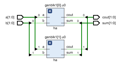
a[0] と b[0] は出力 sum[0] と cout[0] を与え、a[1] と b[1] は出力 sum[1] と cout[1] を与えます。
シミュレーションログncsim> run a=0x0 b=0x0 sum=0x0 cout=0x0 a=0x2 b=0x3 sum=0x1 cout=0x2 a=0x2 b=0x0 sum=0x2 cout=0x0 a=0x1 b=0x0 sum=0x1 cout=0x0 ncsim: *W,RNQUIE: Simulation is complete. ncsim> exit
エラボレートされた RTL には、実際に generate によって生成された 2 つの半加算器インスタンスがあることを確認してください。 ブロックします。
if を生成
以下は、if else を使用した例です。 generate の中 2 つの異なるマルチプレクサの実装から選択するための構造。最初のデザインは assign を使用します 2 番目の設計が case を使用している間にマルチプレクサを実装するステートメント 声明。 USE_CASE と呼ばれるパラメーターが最上位の設計モジュールで定義され、2 つの選択肢から選択されます。
// Design #1: Multiplexer design uses an "assign" statement to assign
// out signal
module mux_assign ( input a, b, sel,
                   output out);
  assign out = sel ? a : b;

  // The initial display statement is used so that
  // we know which design got instantiated from simulation
  // logs
  initial
  	$display ("mux_assign is instantiated");
endmodule

// Design #2: Multiplexer design uses a "case" statement to drive
// out signal
module mux_case (input a, b, sel,
                 output reg out);
  always @ (a or b or sel) begin
  	case (sel)
    	0 : out = a;
   	 	1 : out = b;
  	endcase
  end

  // The initial display statement is used so that
  // we know which design got instantiated from simulation
  // logs
  initial
    $display ("mux_case is instantiated");
endmodule

// Top Level Design: Use a parameter to choose either one
module my_design (	input a, b, sel,
         			output out);
  parameter USE_CASE = 0;

  // Use a "generate" block to instantiate either mux_case
  // or mux_assign using an if else construct with generate
  generate
  	if (USE_CASE)
      mux_case mc (.a(a), .b(b), .sel(sel), .out(out));
    else
      mux_assign ma (.a(a), .b(b), .sel(sel), .out(out));
  endgenerate

endmodule
テストベンチ
テストベンチは最上位モジュール my_design をインスタンス化し、パラメータ USE_CASE を 1 に設定して、case を使用してデザインをインスタンス化します。
module tb;
	// Declare testbench variables
  reg a, b, sel;
  wire out;
  integer i;

  // Instantiate top level design and set USE_CASE parameter to 1 so that
  // the design using case statement is instantiated
  my_design #(.USE_CASE(1)) u0 ( .a(a), .b(b), .sel(sel), .out(out));

  initial begin
  	// Initialize testbench variables
  	a <= 0;
    b <= 0;
    sel <= 0;

    // Assign random values to DUT inputs with some delay
    for (i = 0; i < 5; i = i + 1) begin
      #10 a <= $random;
      	  b <= $random;
          sel <= $random;
      $display ("i=%0d a=0x%0h b=0x%0h sel=0x%0h out=0x%0h", i, a, b, sel, out);
    end
  end
endmodule
パラメータ USE_CASE が 1 の場合、シミュレーション ログから、マルチプレクサが case を使用して設計されていることがわかります。 ステートメントがインスタンス化されます。 USE_CASE が 0 の場合、assign を使用するマルチプレクサ デザイン ステートメントがインスタンス化されます。これは、シミュレーション ログに出力される表示ステートメントから確認できます。
// When USE_CASE = 1
ncsim> run
mux_case is instantiated
i=0 a=0x0 b=0x0 sel=0x0 out=0x0
i=1 a=0x0 b=0x1 sel=0x1 out=0x1
i=2 a=0x1 b=0x1 sel=0x1 out=0x1
i=3 a=0x1 b=0x0 sel=0x1 out=0x0
i=4 a=0x1 b=0x0 sel=0x1 out=0x0
ncsim: *W,RNQUIE: Simulation is complete.

// When USE_CASE = 0
ncsim> run
mux_assign is instantiated
i=0 a=0x0 b=0x0 sel=0x0 out=0x0
i=1 a=0x0 b=0x1 sel=0x1 out=0x0
i=2 a=0x1 b=0x1 sel=0x1 out=0x1
i=3 a=0x1 b=0x0 sel=0x1 out=0x1
i=4 a=0x1 b=0x0 sel=0x1 out=0x1
ncsim: *W,RNQUIE: Simulation is complete.
ケースを生成
生成ケースを使用すると、モジュール、初期ブロック、常にブロックを case に基づいて別のモジュールでインスタンス化できます 多くの選択肢の中から 1 つを選択する式。
// Design #1: Half adder
module ha (input a, b,
           output reg sum, cout);
  always @ (a or b)
  {cout, sum} = a + b;

  initial
    $display ("Half adder instantiation");
endmodule

// Design #2: Full adder
module fa (input a, b, cin,
           output reg sum, cout);
  always @ (a or b or cin)
  {cout, sum} = a + b + cin;

    initial
      $display ("Full adder instantiation");
endmodule

// Top level design: Choose between half adder and full adder
module my_adder (input a, b, cin,
                 output sum, cout);
  parameter ADDER_TYPE = 1;

  generate
    case(ADDER_TYPE)
      0 : ha u0 (.a(a), .b(b), .sum(sum), .cout(cout));
      1 : fa u1 (.a(a), .b(b), .cin(cin), .sum(sum), .cout(cout));
    endcase
  endgenerate
endmodule
テストベンチ
module tb;
  reg a, b, cin;
  wire sum, cout;

  my_adder #(.ADDER_TYPE(0)) u0 (.a(a), .b(b), .cin(cin), .sum(sum), .cout(cout));

  initial begin
    a <= 0;
    b <= 0;
    cin <= 0;

    $monitor("a=0x%0h b=0x%0h cin=0x%0h cout=0%0h sum=0x%0h",
             a, b, cin, cout, sum);

    for (int i = 0; i < 5; i = i + 1) begin
      #10 a <= $random;
      b <= $random;
      cin <= $random;
    end
  end
endmodule
半加算器がインスタンス化されるため、cin は出力 sum と cout に影響を与えないことに注意してください。
シミュレーションログncsim> run Half adder instantiation a=0x0 b=0x0 cin=0x0 cout=00 sum=0x0 a=0x0 b=0x1 cin=0x1 cout=00 sum=0x1 a=0x1 b=0x1 cin=0x1 cout=01 sum=0x0 a=0x1 b=0x0 cin=0x1 cout=00 sum=0x1 ncsim: *W,RNQUIE: Simulation is complete.
Verilog