


モバイルリモート監視カメラ
コンポーネントと消耗品
>  |
| × | 1 | |||
| × | 1 | ||||
 |
| × | 1 | |||
 |
| × | 1 | |||
 |
| × | 1 |
必要なツールとマシン
| ||||
| ||||
| ||||
| ||||
| ||||
 |
| |||
|
このプロジェクトについて
この興味深いが複雑なプロジェクトでは、ロボットの構築の設計から、Linux(raspberry pi)の高度な構成、Androidアプリケーションの構築、ロボットの制御まで、さまざまなことをカバーします。
つまり、これは平均的なプロジェクトよりも野心的だと言われていますが、ここでいくつかのアイデアを検討したり、プロジェクト全体を複製したりすることで、学ぶことがたくさんあると思います。
まず、プレキシガラス、プラスチックシート、ギアボックス付きのDCモーター、およびさまざまな電子部品を使用してロボットを構築します。デバイスは2つの前輪を独立して動かすことができ、ヘッドライトを使用できるようになります。次に、ロボットに電力を供給するラズベリーパイをセットアップし、プロジェクトを構成して、さまざまな依存関係をインストールします。次に、Androidアプリをビルドしてインストールし、それを使用して、カメラとWi-Fi接続を使用してロボットをリモートで制御します。
テクノロジーとコンセプトはここで探求されます :
開発プラットフォーム:Arduino、Raspberry pi、Android
エレクトロニクス:Hブリッジ、トランジスタを使用して大きな負荷を駆動する赤外線センサー
Linux:docker、docker composeの使用、systemctlを使用したサービスの構成、ビデオストリーミング
プログラミング:Androidアプリケーション、Python、arduino言語、シリアル通信、MQTT
ステップ1:必要なもの <図>
 <図>
<図> 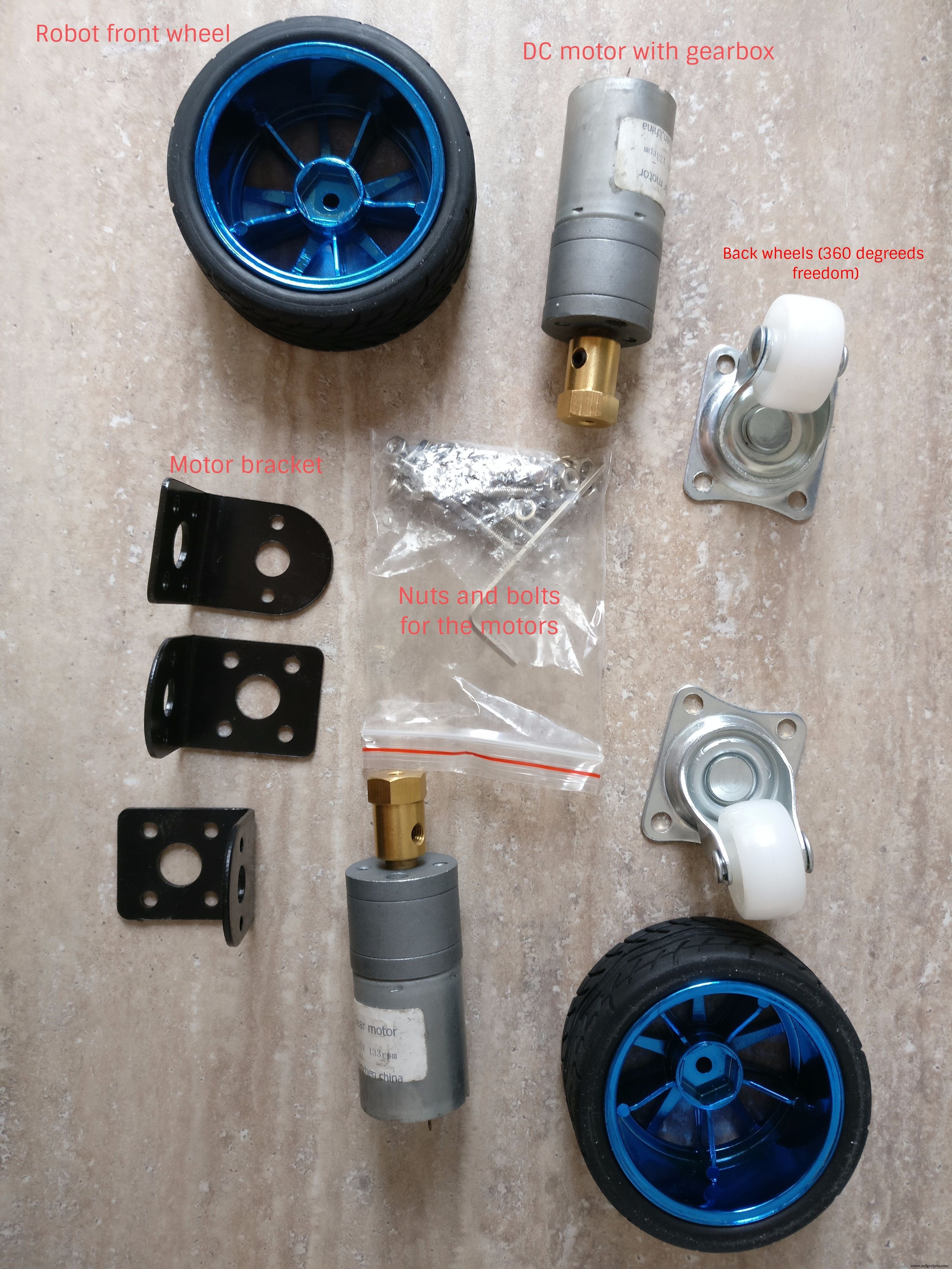
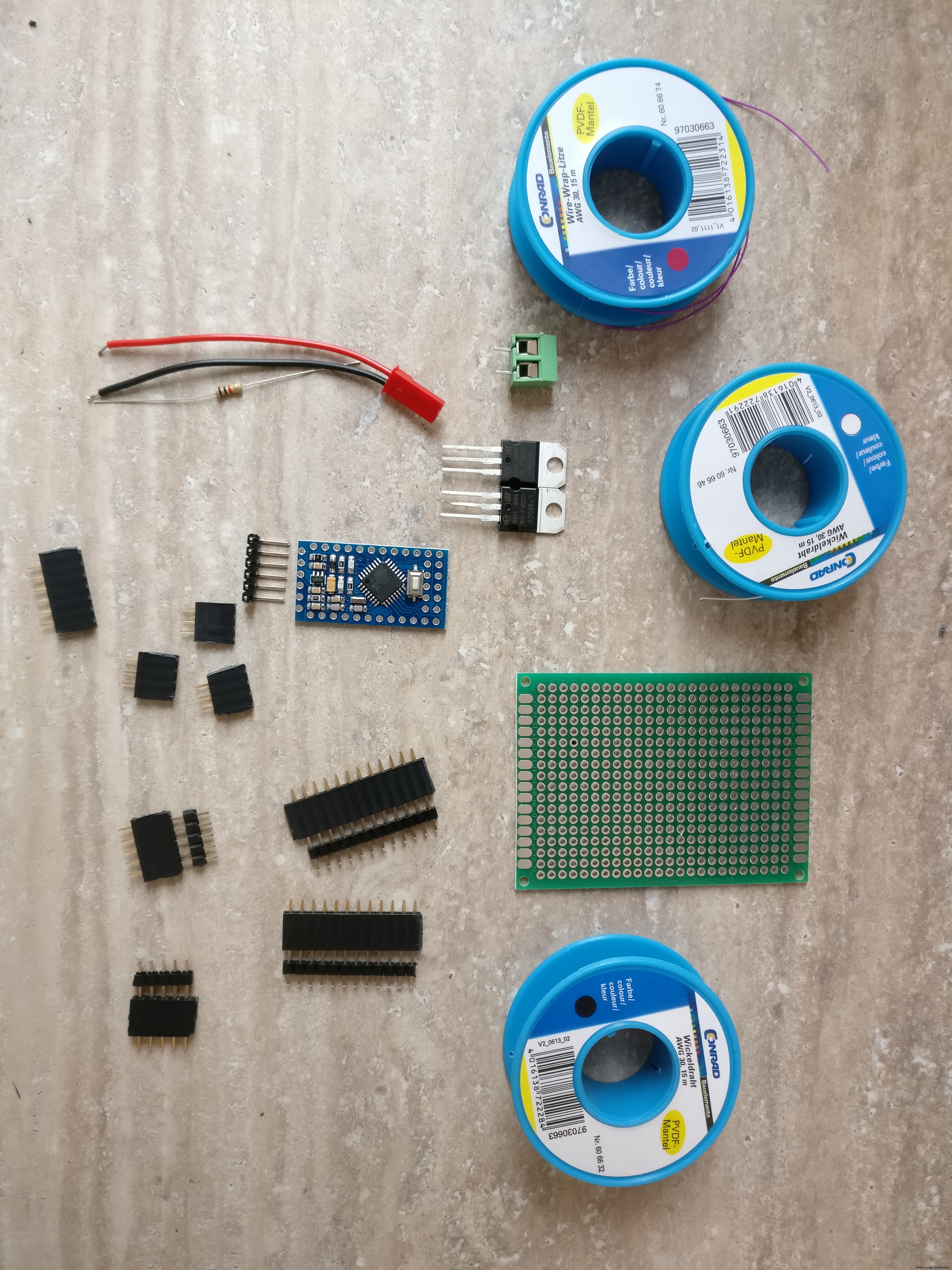
パーツ:
1.プレキシガラスシート
2.プラスチックシート(ここでプレキシガラスシートを使用することもできます)
3.接着剤
4.ギアボックス+ブラケット付きのタイヤ+ DCモーター。小さなナットとボルト、六角形の金属スペーサー
6. 2x任意の方向性ホイールタイヤ
7.小型LED懐中電灯(ヘッドライトに変換されます)
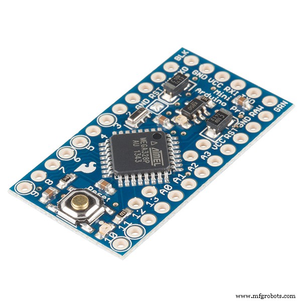
8. Arduino pro mini 328p
9. 2x赤外線障害物センサー
10. PCB
11. NPNトランジスタ(懐中電灯を駆動するため)
12. L7805CV5Vレギュレーター
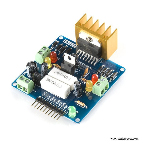
13. L298Hブリッジ
14.抵抗220オーム
15.オスUSBコネクタ
16.オスマイクロUSBコネクタ
17.さまざまなワイヤー
18. 3 vレギュレーター(arduinoとラズベリーパイ間の通信用)
19.オスおよびメスのPCBコネクタ
20.オン/オフスイッチ
21.XT-60メスLiPoコネクタ
22.XT-60コネクタ付き2S1300 mAhLiPoバッテリー
23.5vバッテリーパック
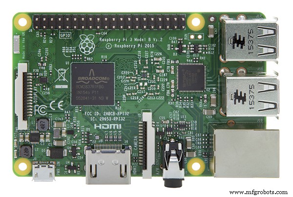
24.ラズベリーパイ3
25.ラズベリーパイカード
26.ラズベリーパイケース
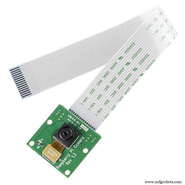
27.ラズベリーパイカメラ
ツール: 1. arduino prominiをプログラムするためのUSB-シリアルFTDIアダプターFT232RL
2. Arduino IDE
3.ドリル
4.ファインブレードソー
5.ドライバー
6.はんだごて
7.ワイヤーカッター
スキル:
1.はんだ付け、このチュートリアルを確認してください
2.基本的なarduinoプログラミング、このチュートリアルは役に立つかもしれません
3. Linuxサービスの構成、パッケージのインストール
ステップ2:ロボットプラットフォームを構築する
ロボット ビルドするのは、次の仕様です。 :
-2つの別々のDCモーターによって前輪を牽引します
-後輪は360度任意の方向に移動できる必要があります
-方向は前輪の速度を変えることによって制御されるので、個別の方向メカニズムは必要ありません。また、ロボットはその場で回転することができます
-上部にライトがあります
-電子機器、バッテリー、カメラ付きのラズベリーパイケースを収納するのに十分なスペースが必要です
-小さな障害物を克服するには、数cmの最低地上高が必要です
重要な詳細と構築のヒントについては、画像を確認することを忘れないでください。
<図>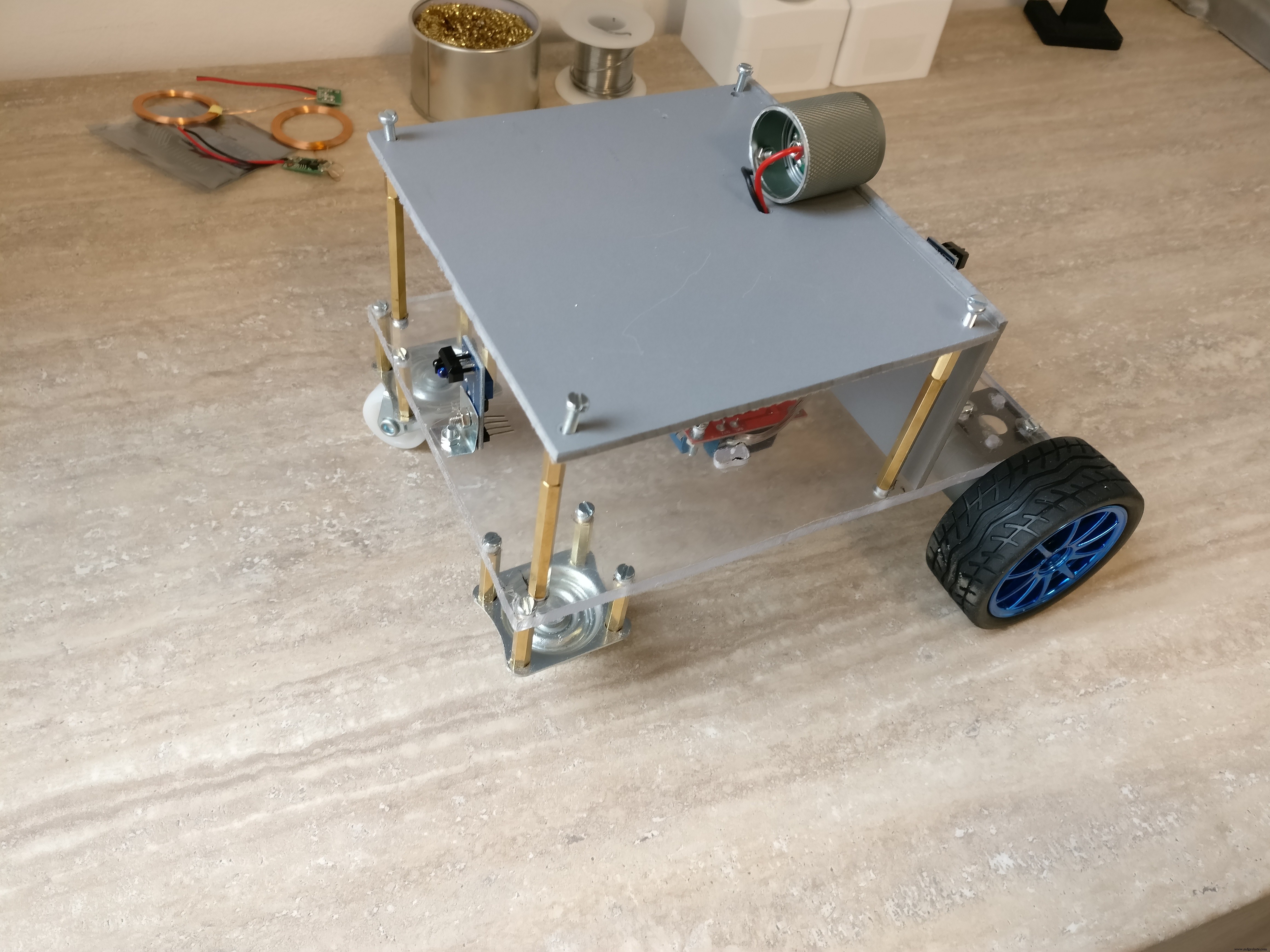 <図>
<図>  <図>
<図> 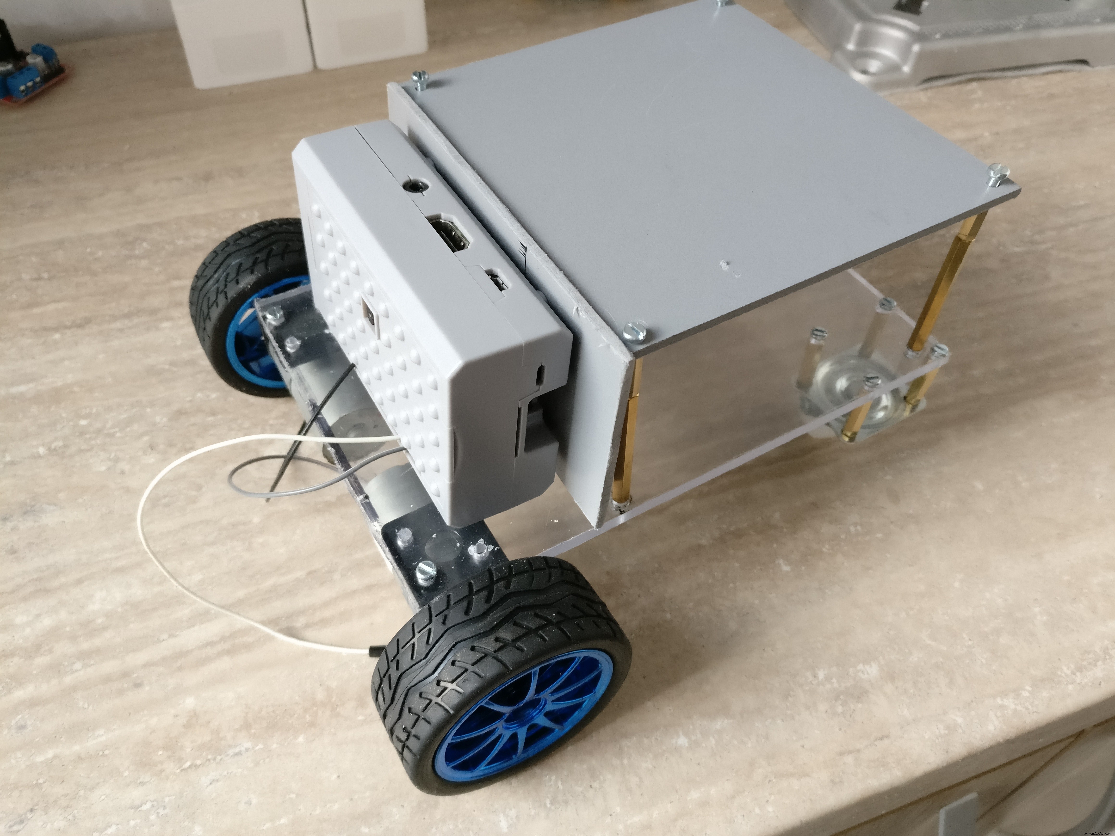 <図>
<図> 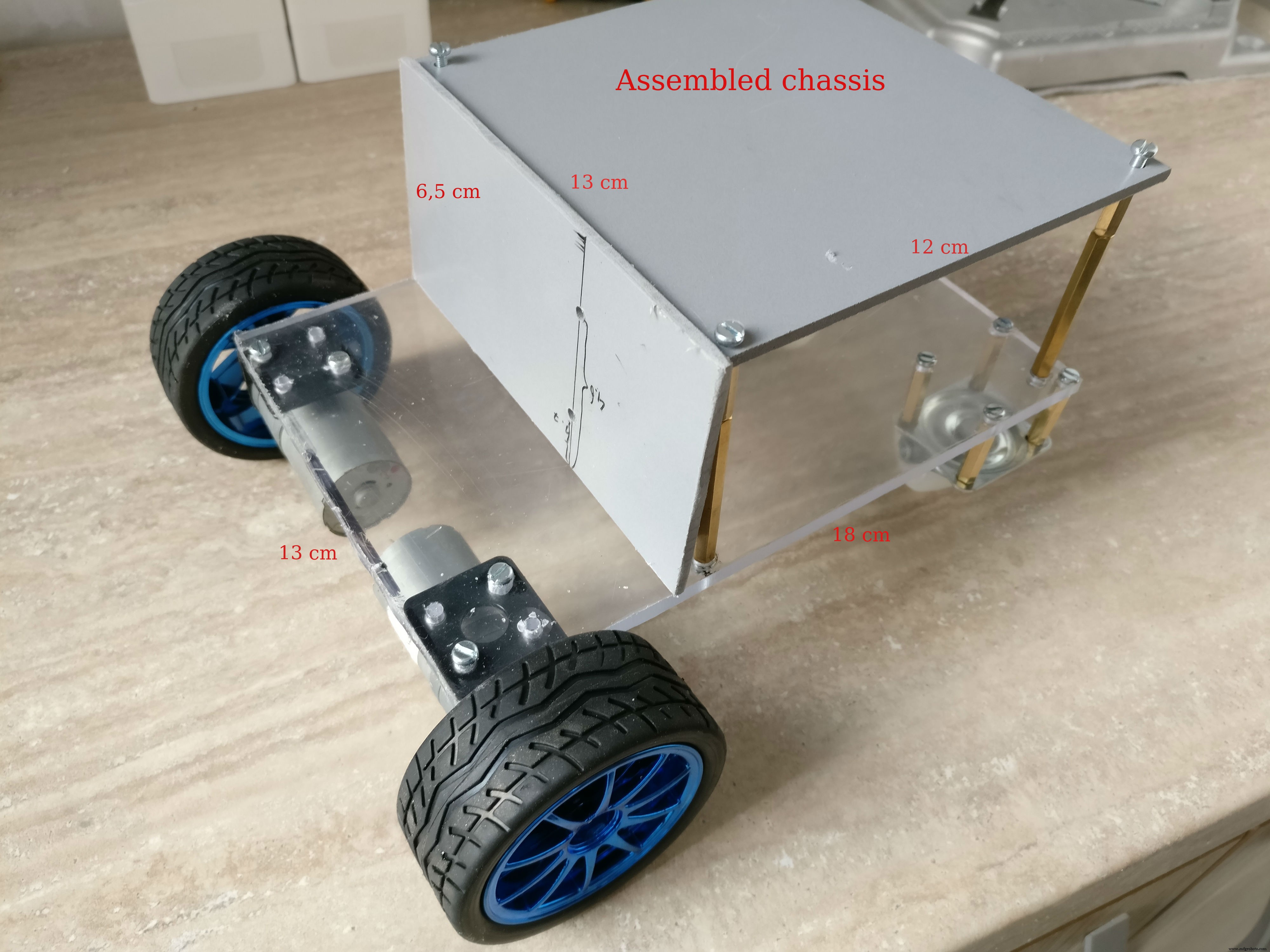 <図>
<図> 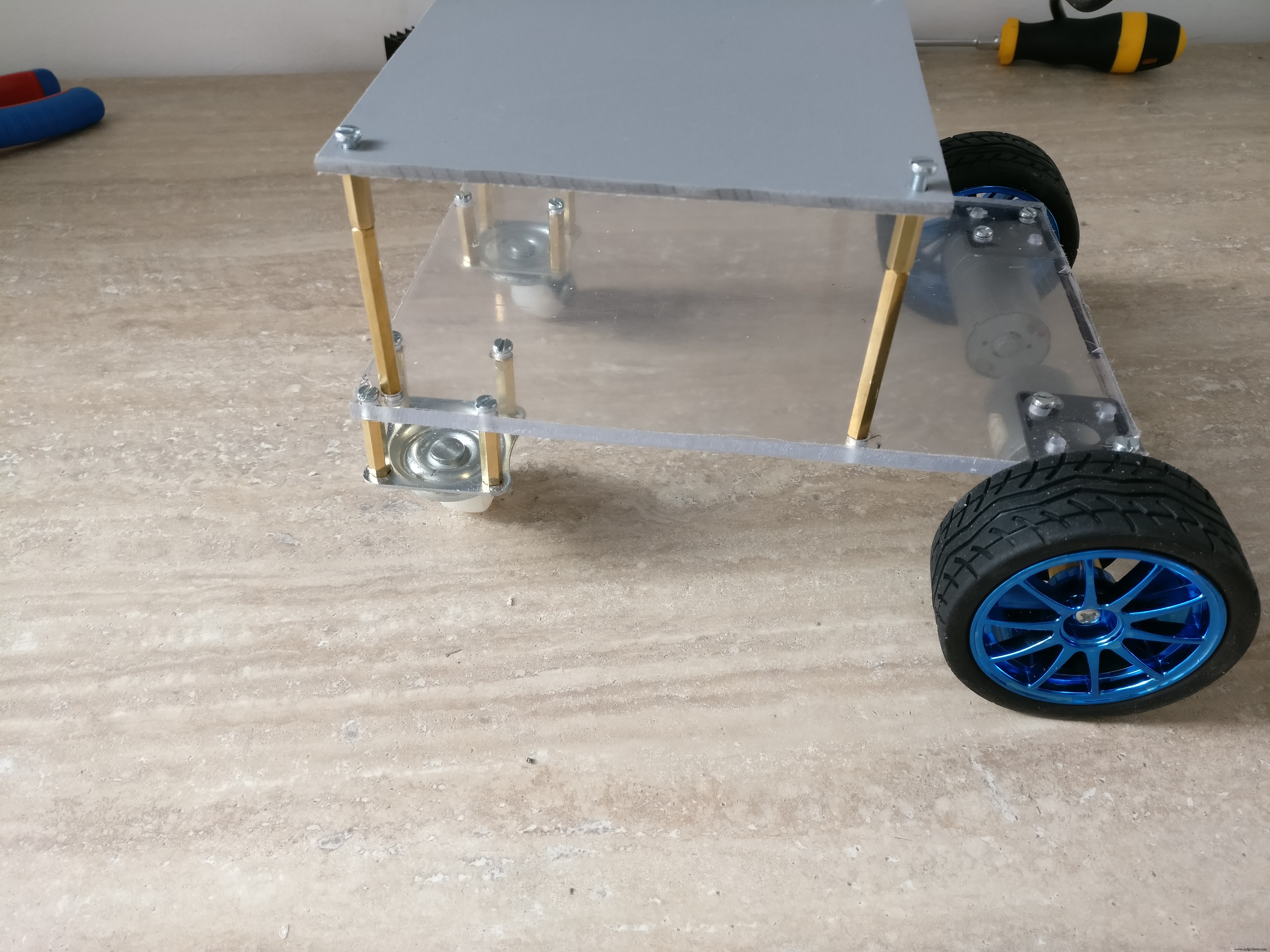 <図>
<図> 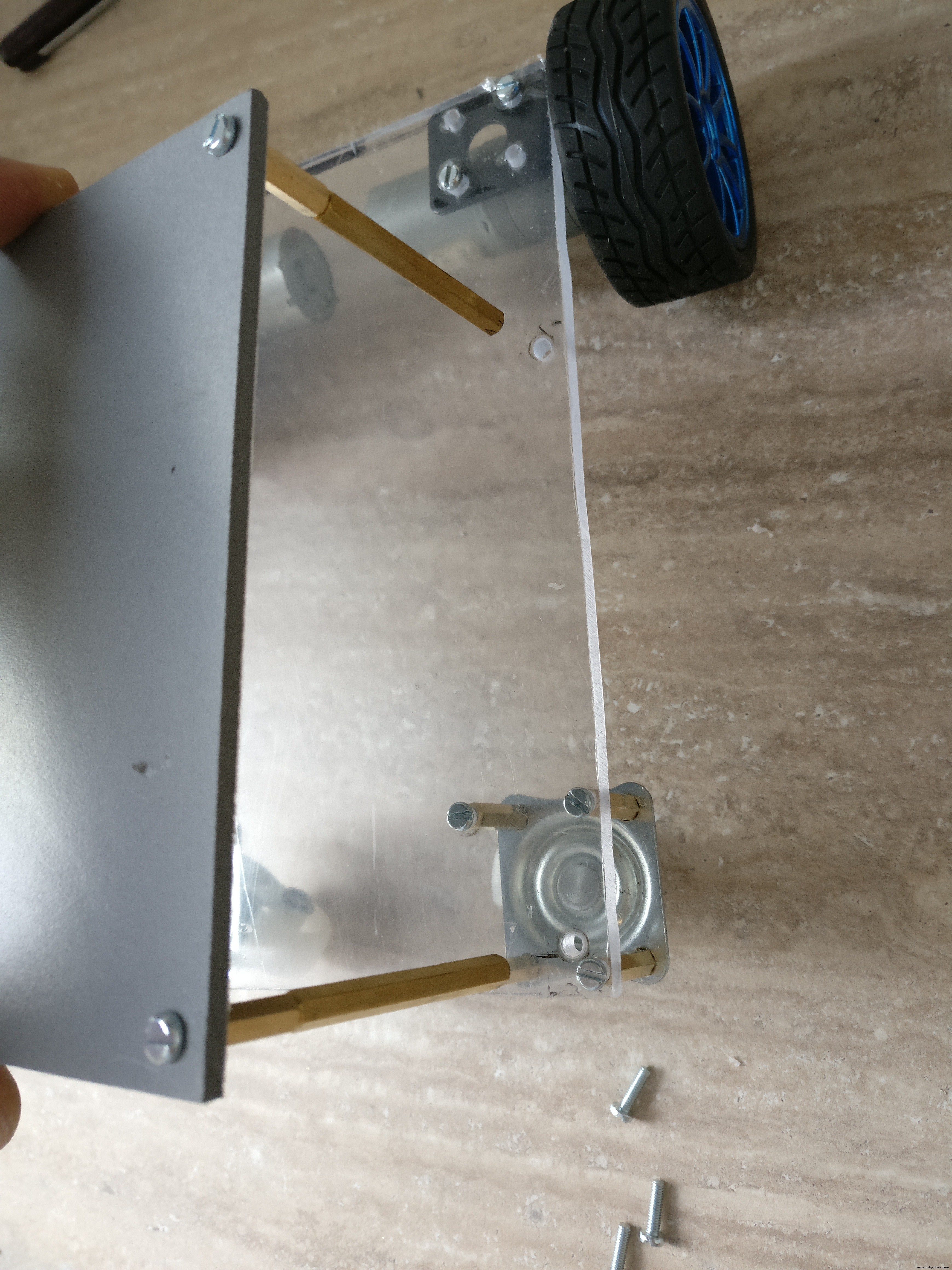 <図>
<図>  <図>
<図>  <図>
<図> 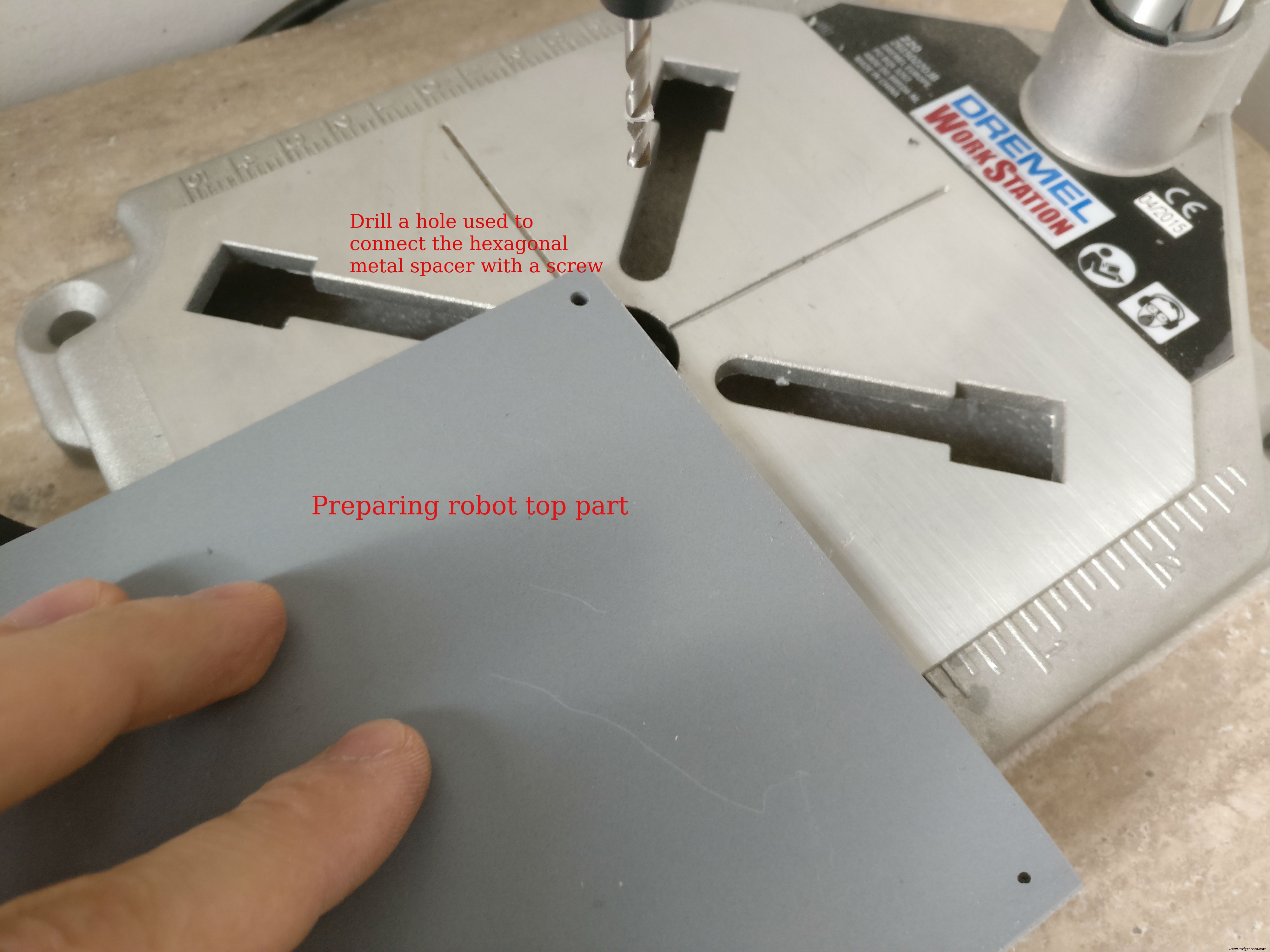 <図>
<図> 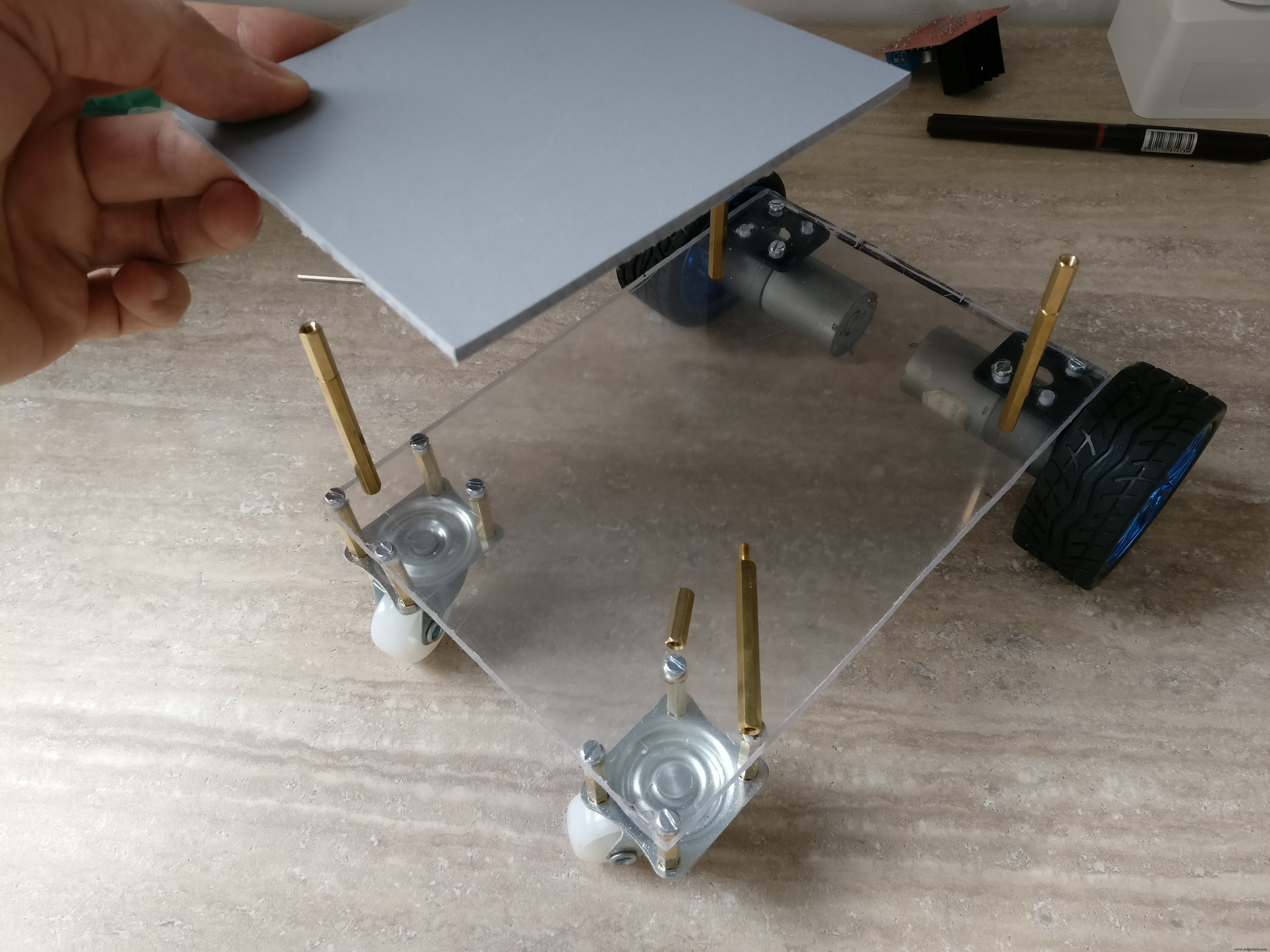 <図>
<図> 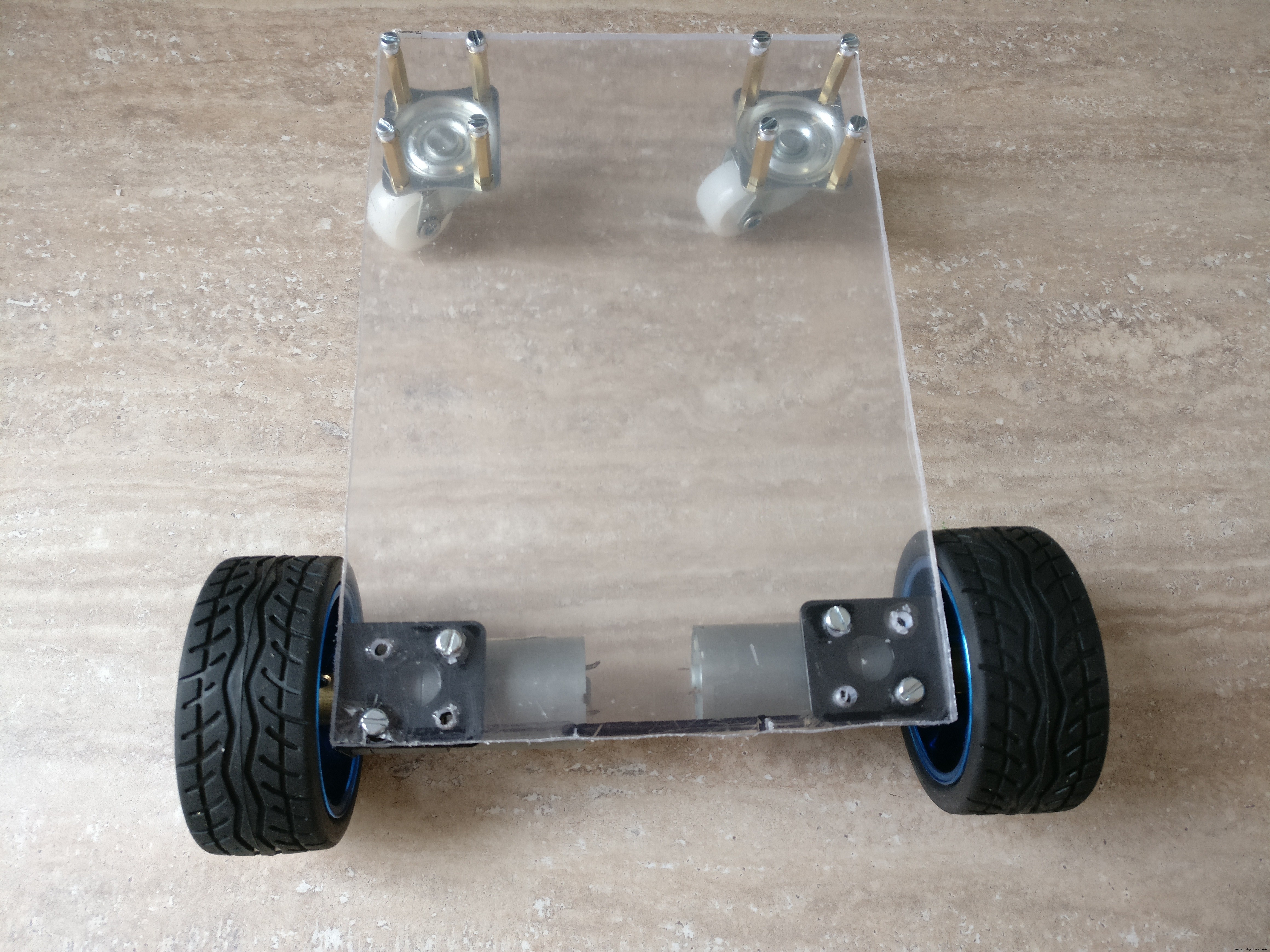 <図>
<図> 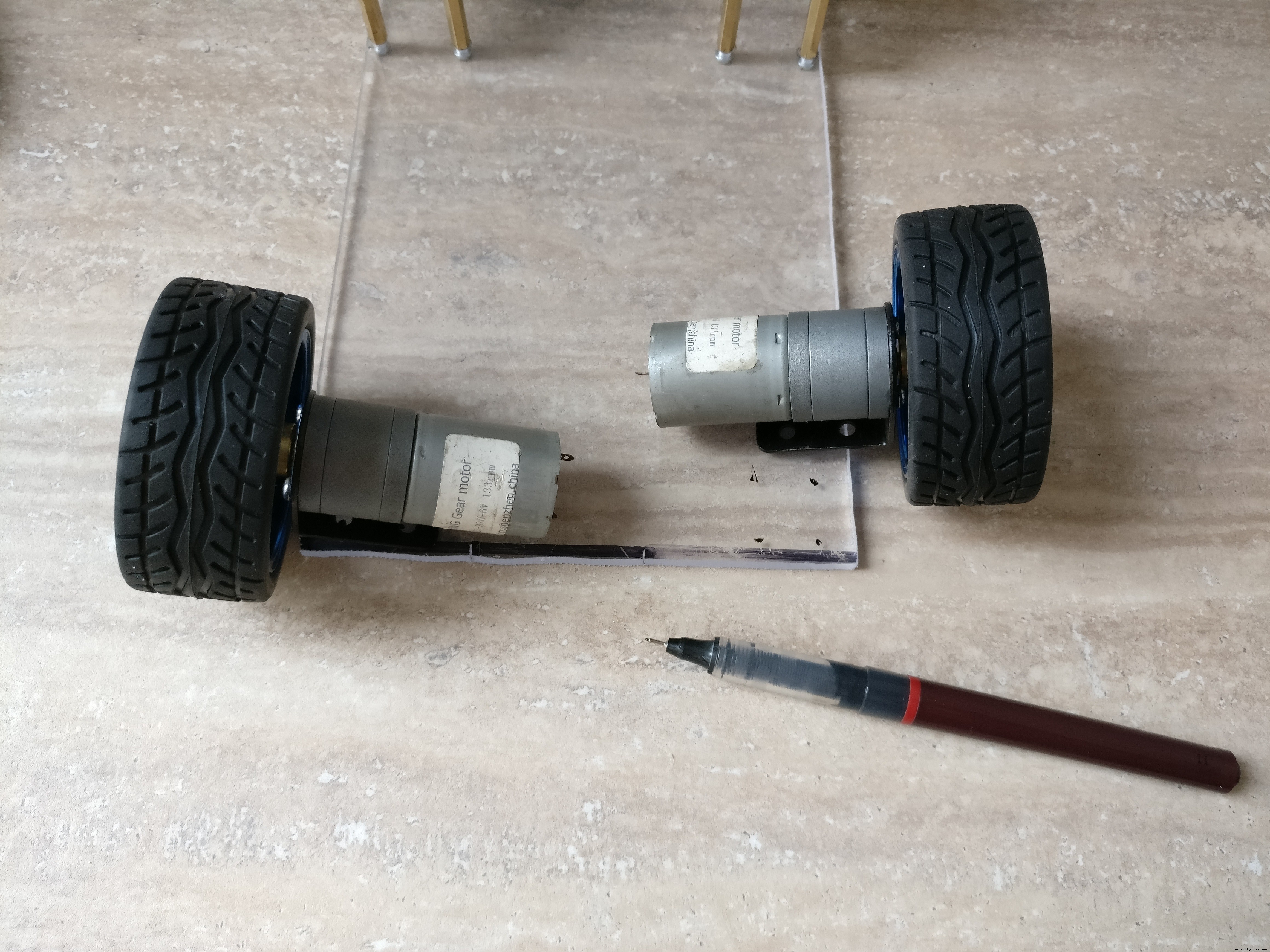 <図>
<図> 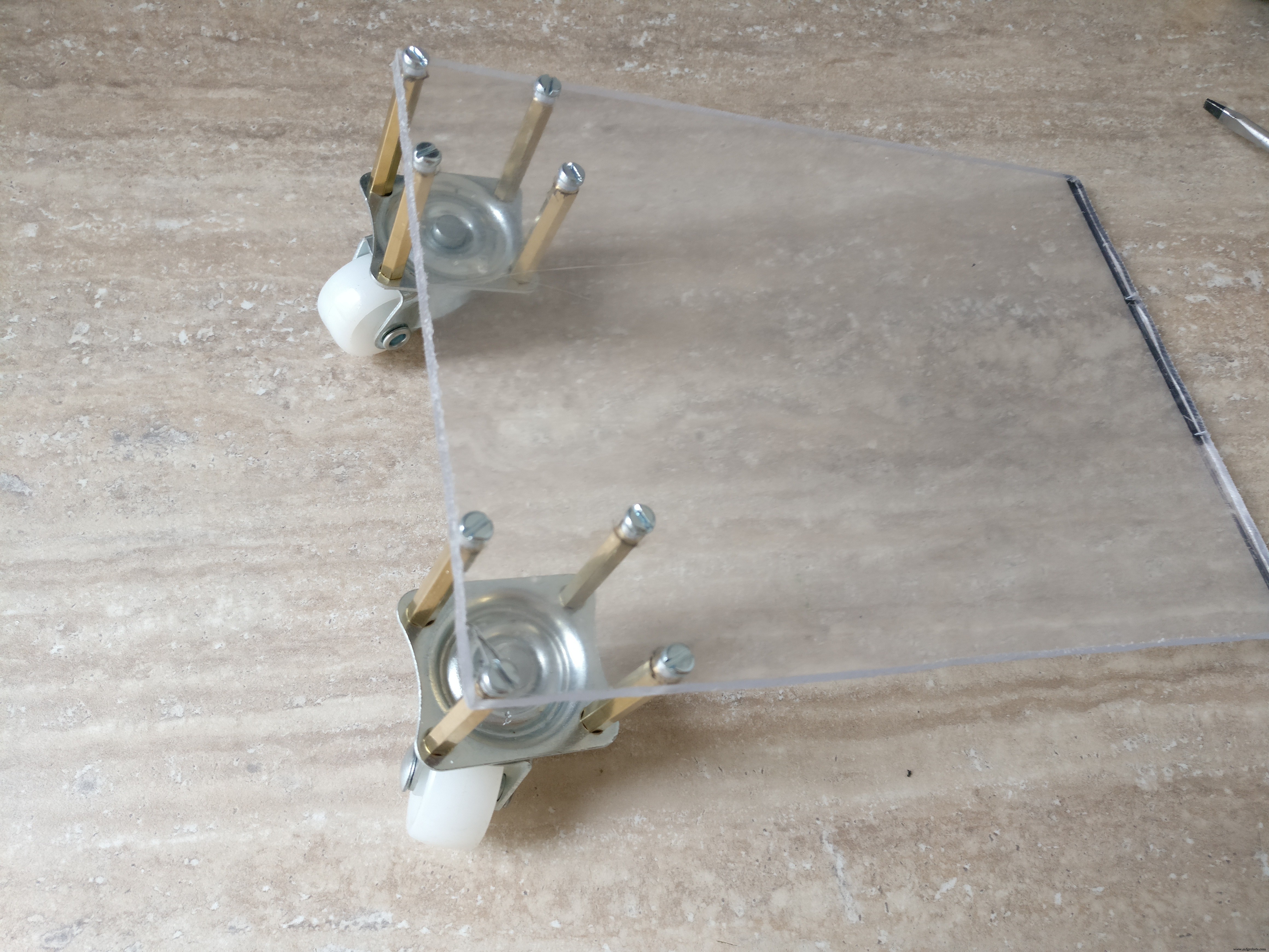 <図>
<図> 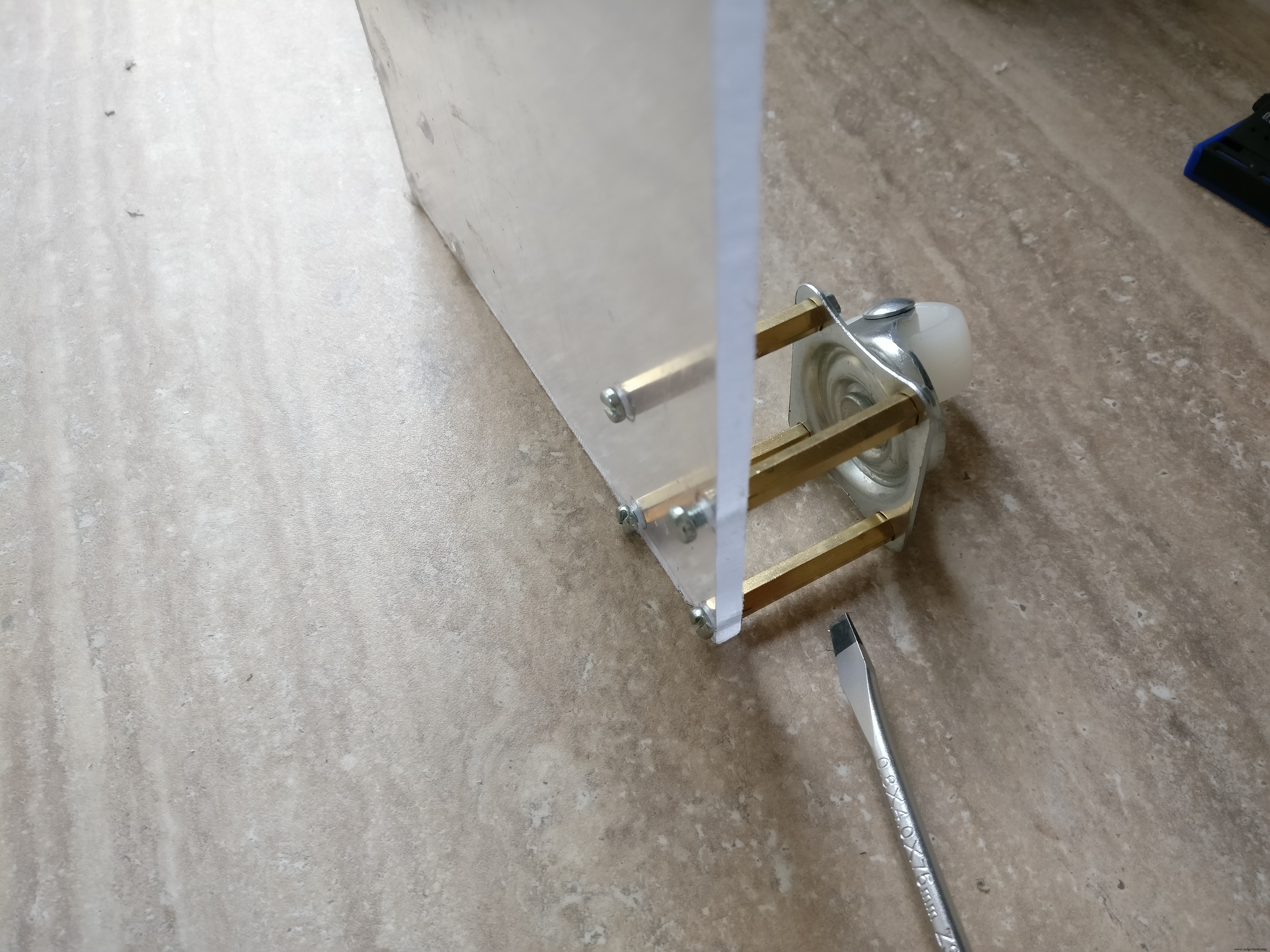 <図>
<図> 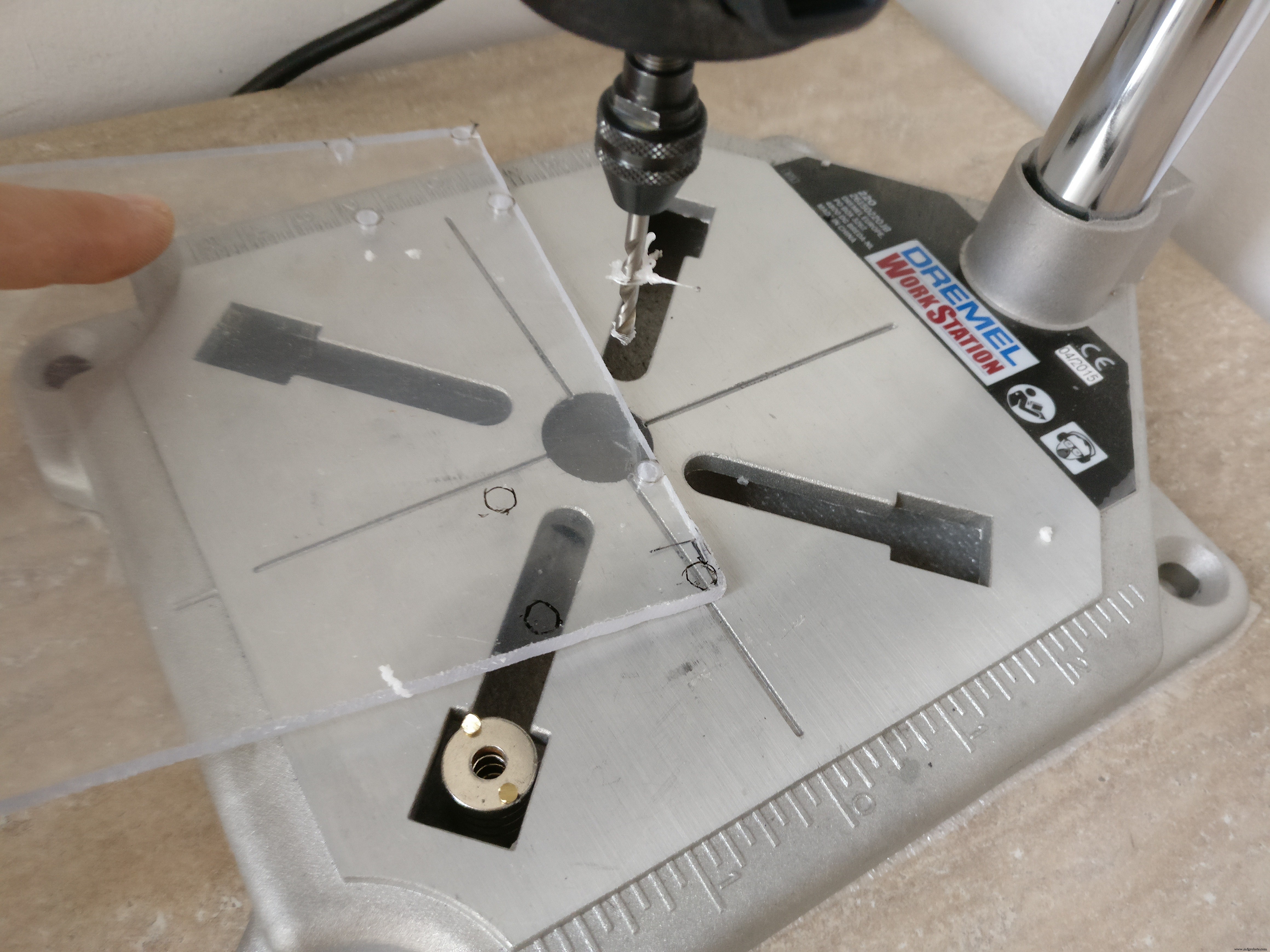 <図>
<図> 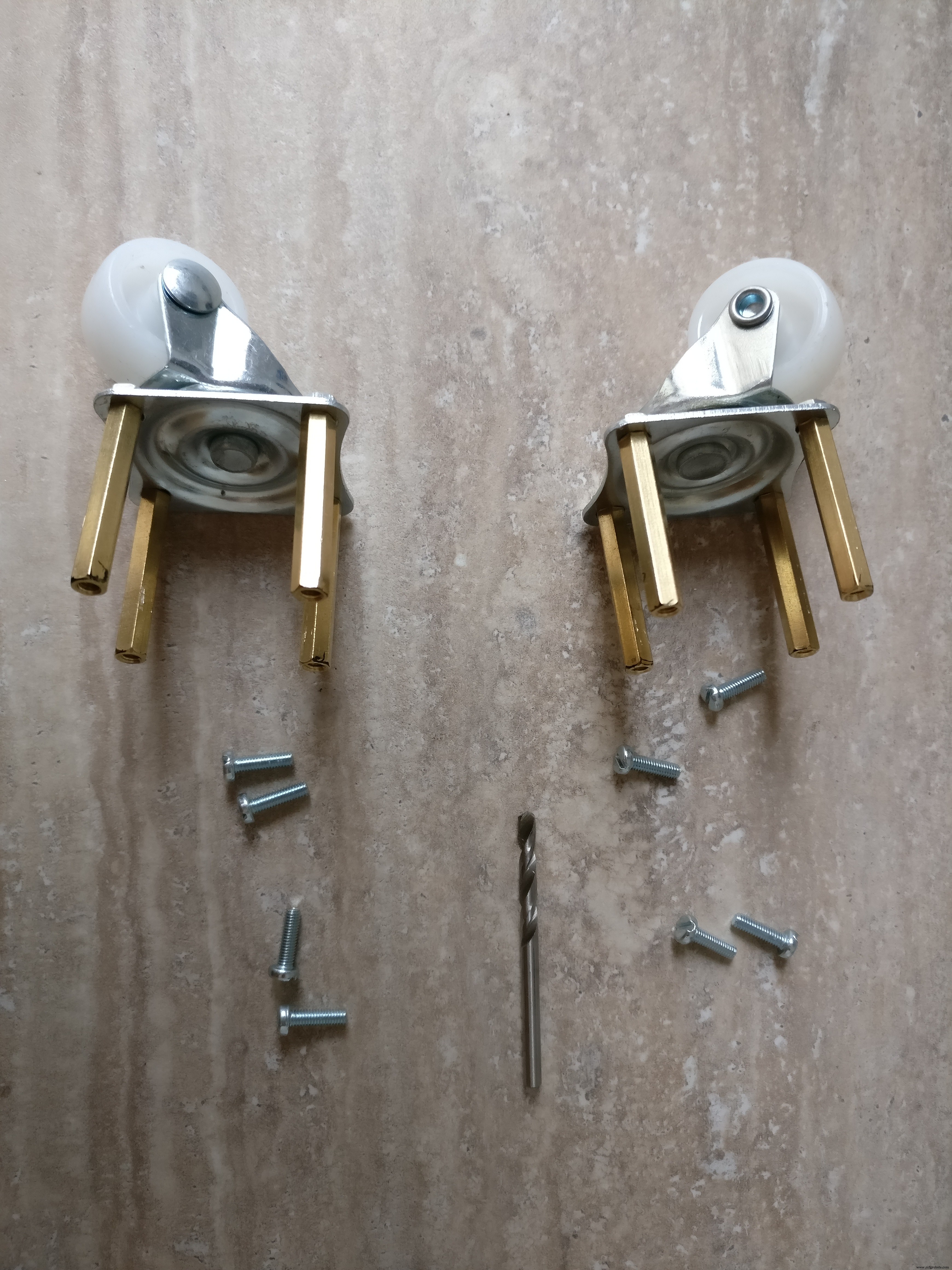 <図>
<図> 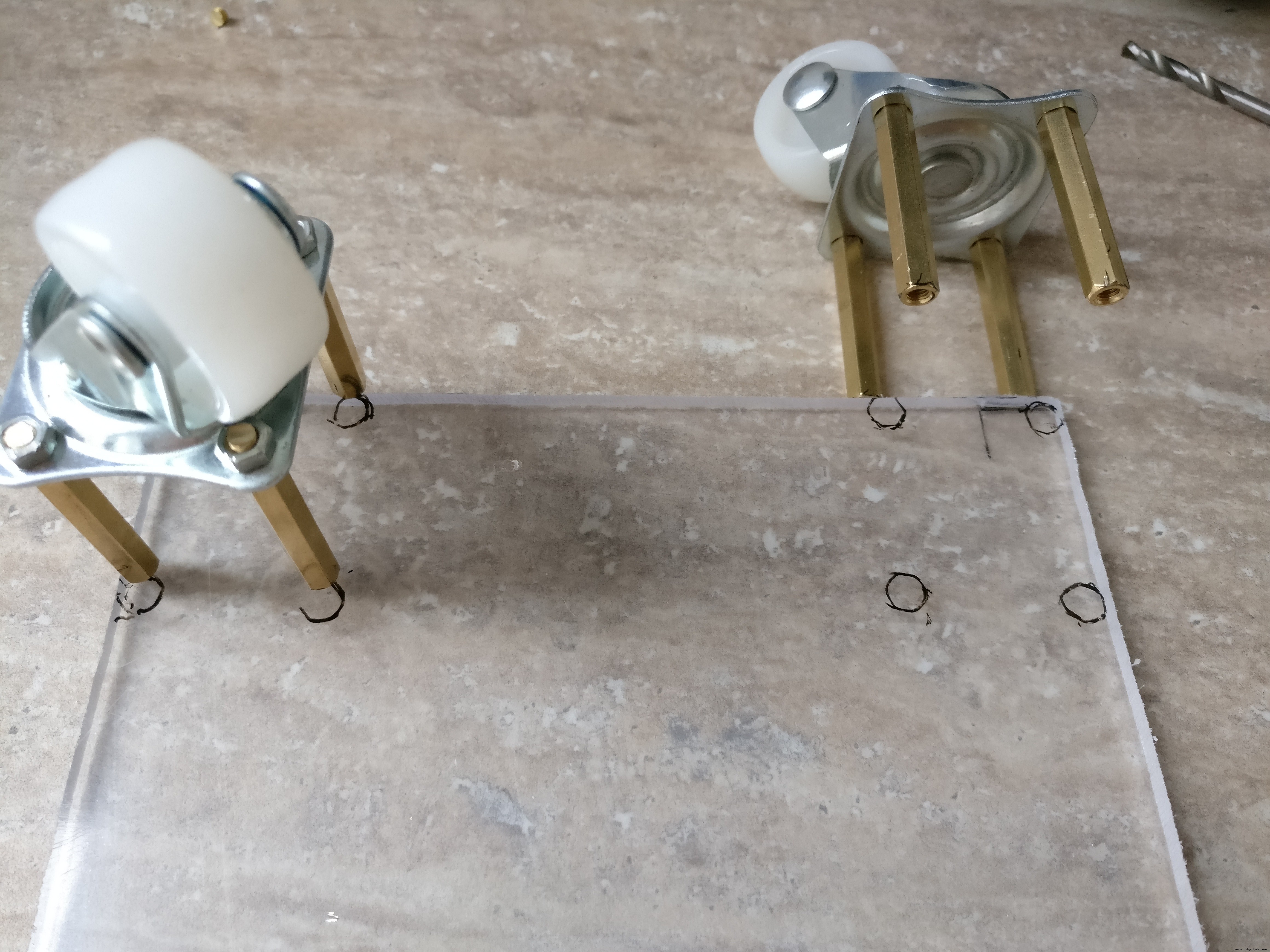 <図>
<図> 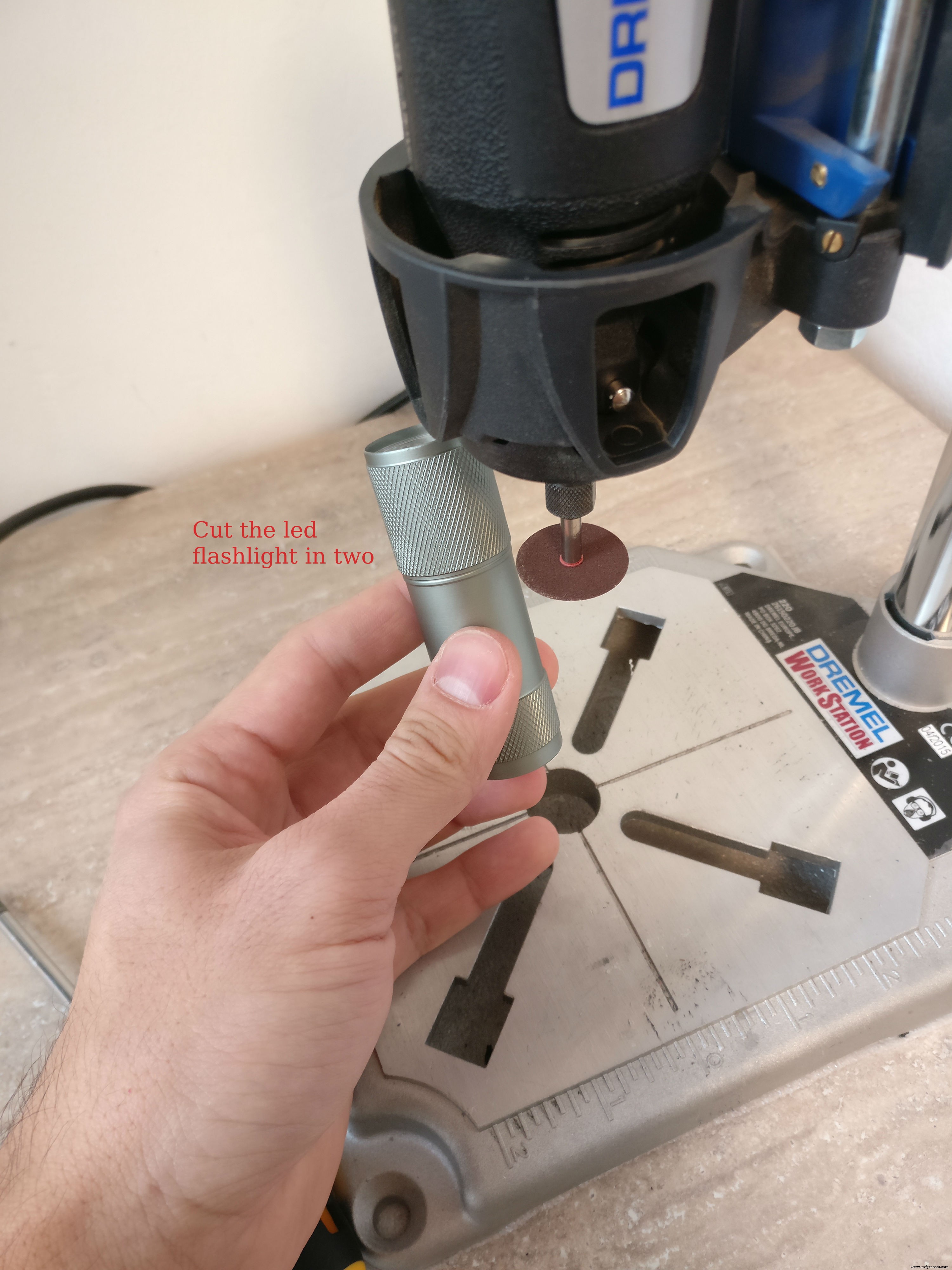 <図>
<図> 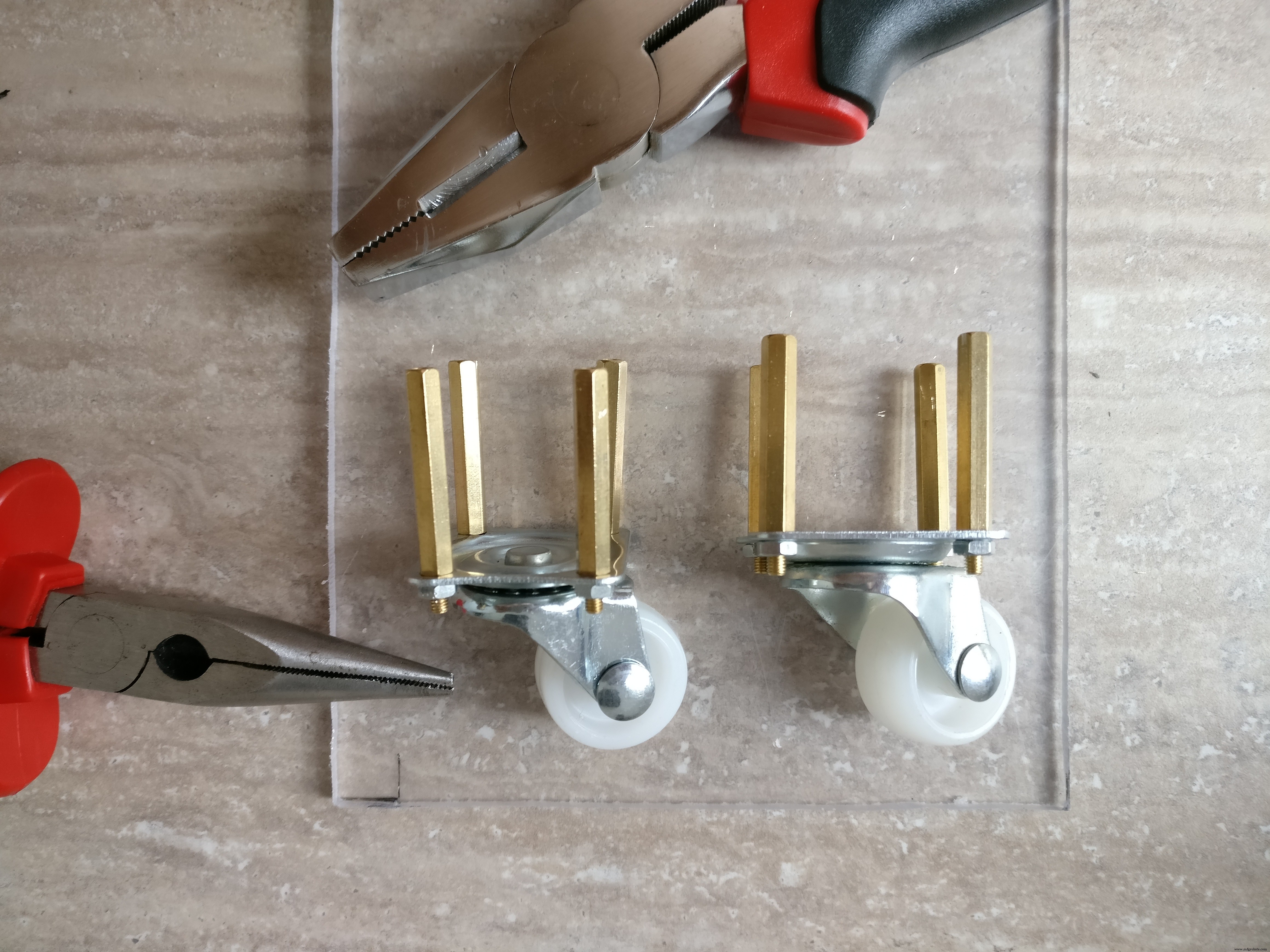 <図>
<図> 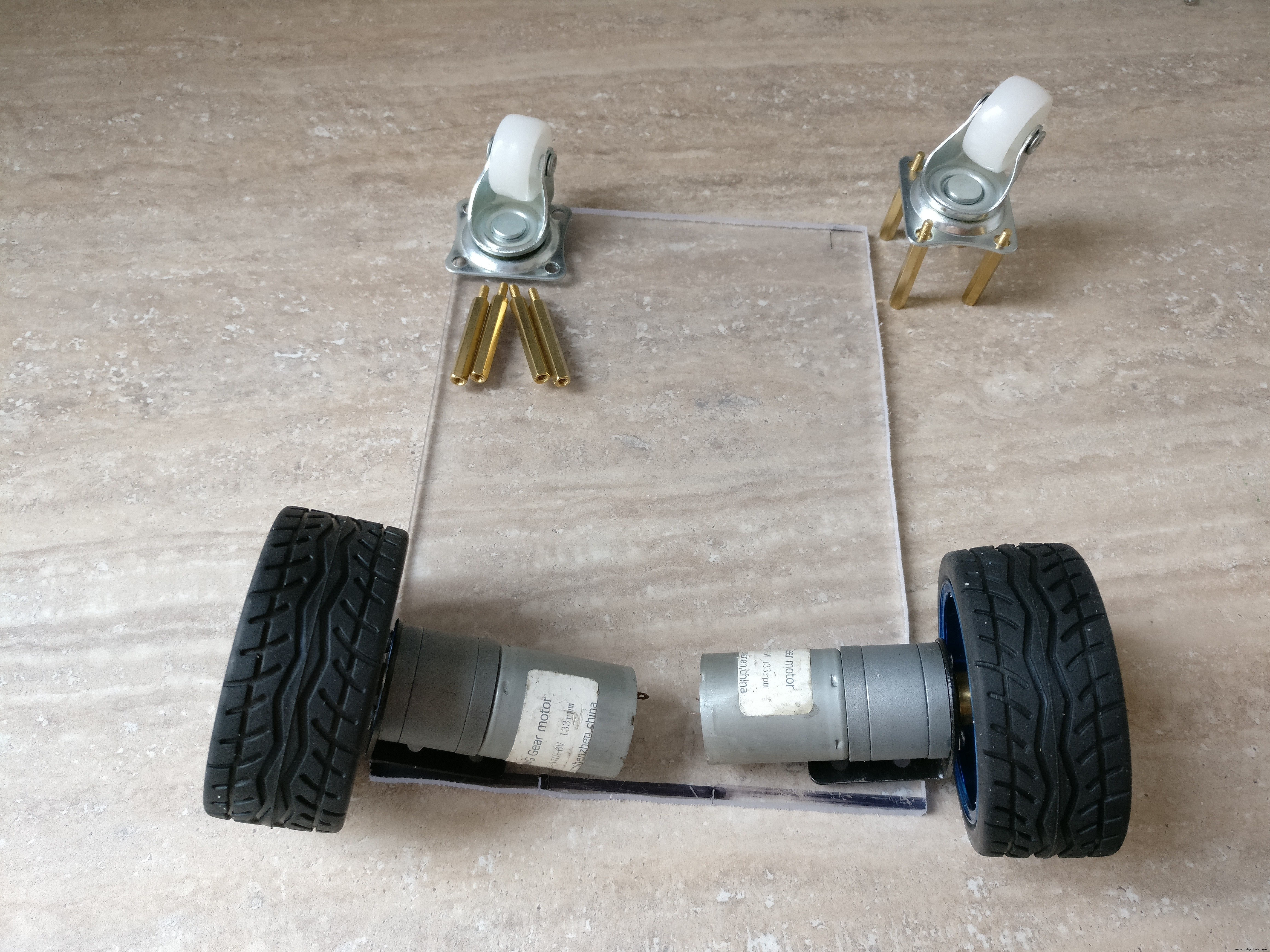 <図>
<図> 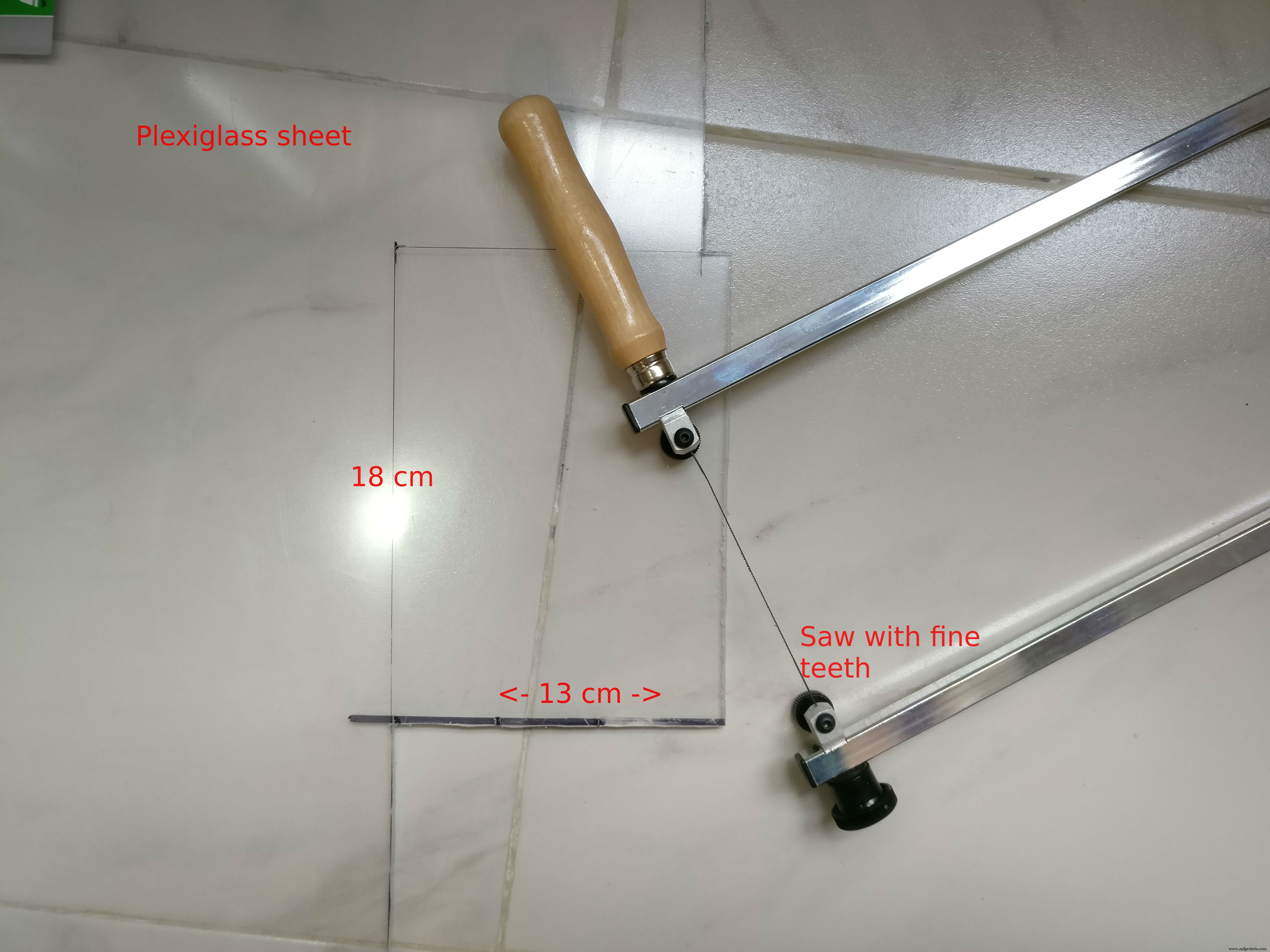 <図>
<図> 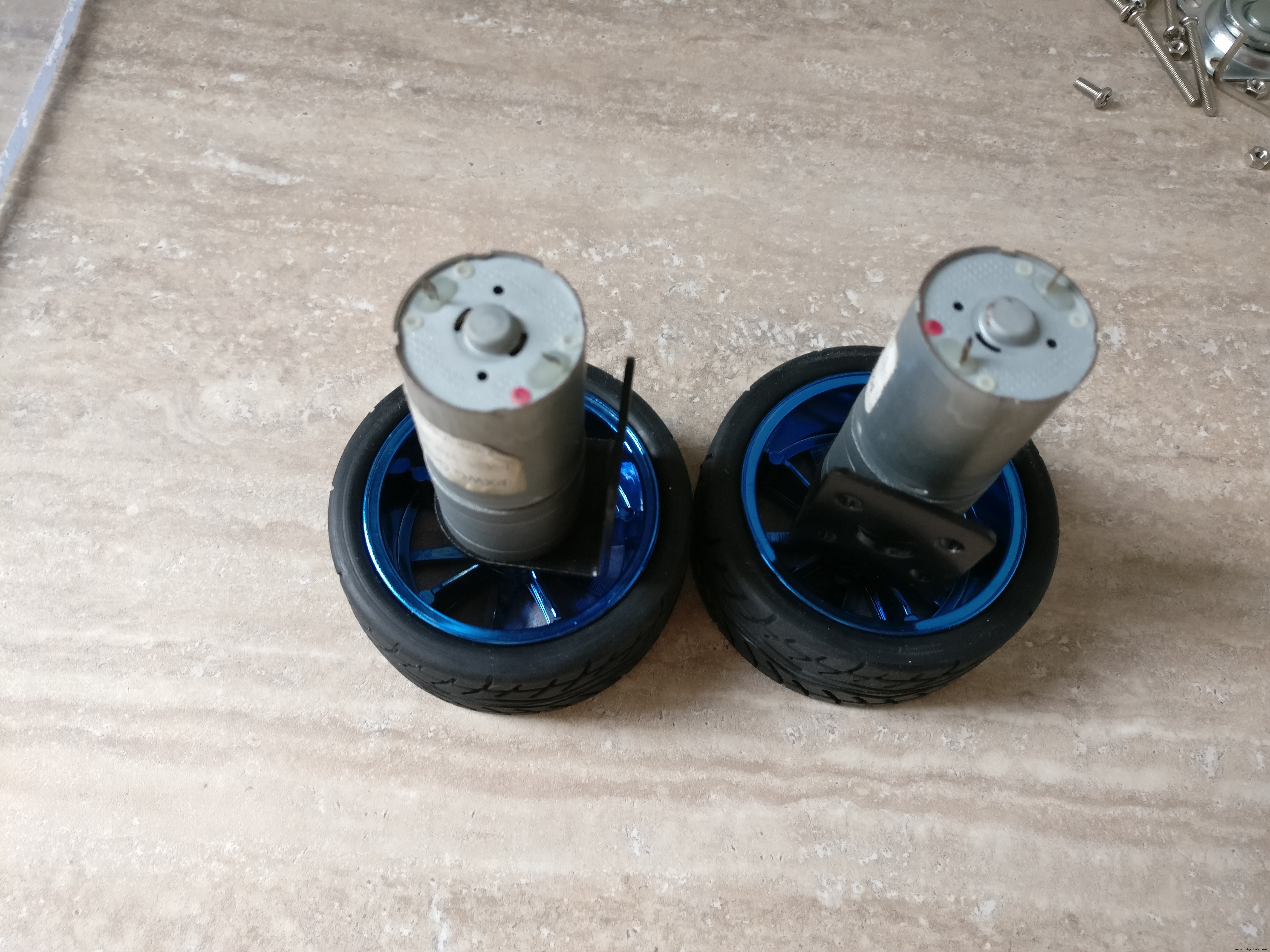 <図>
<図>  <図>
<図> 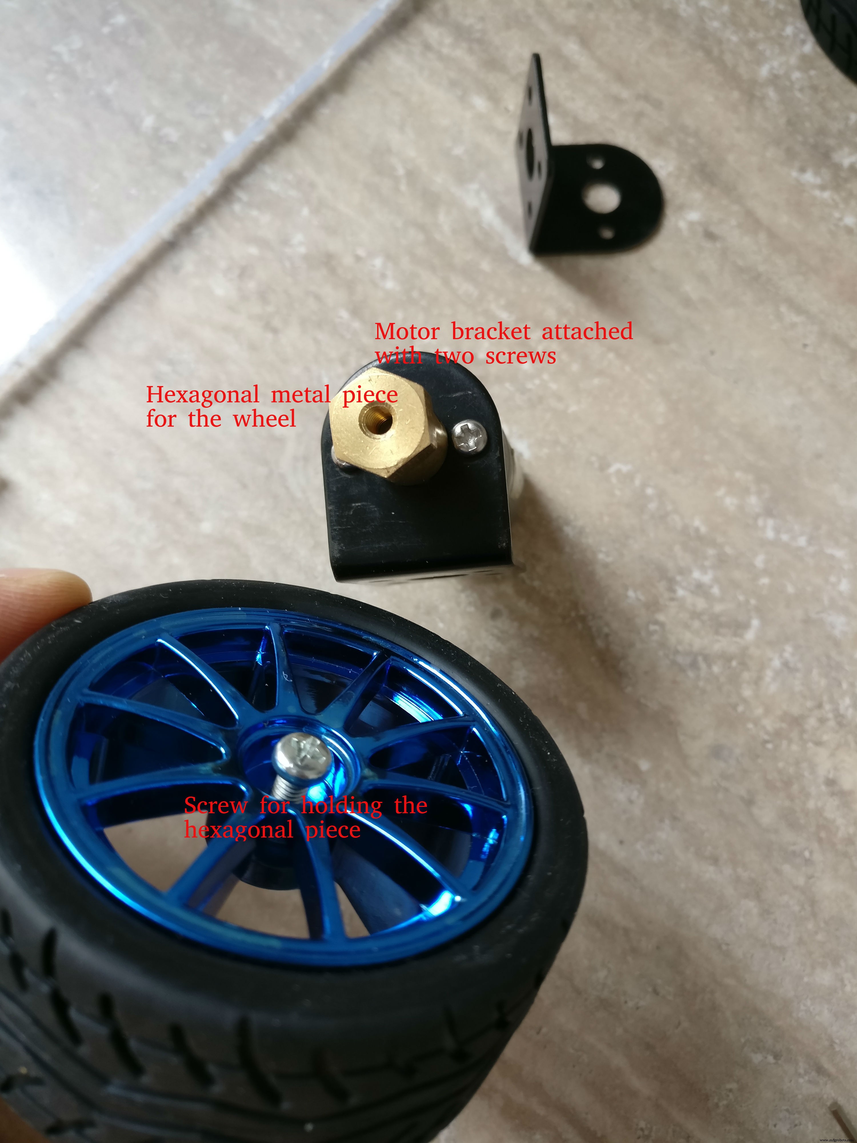 <図>
<図> 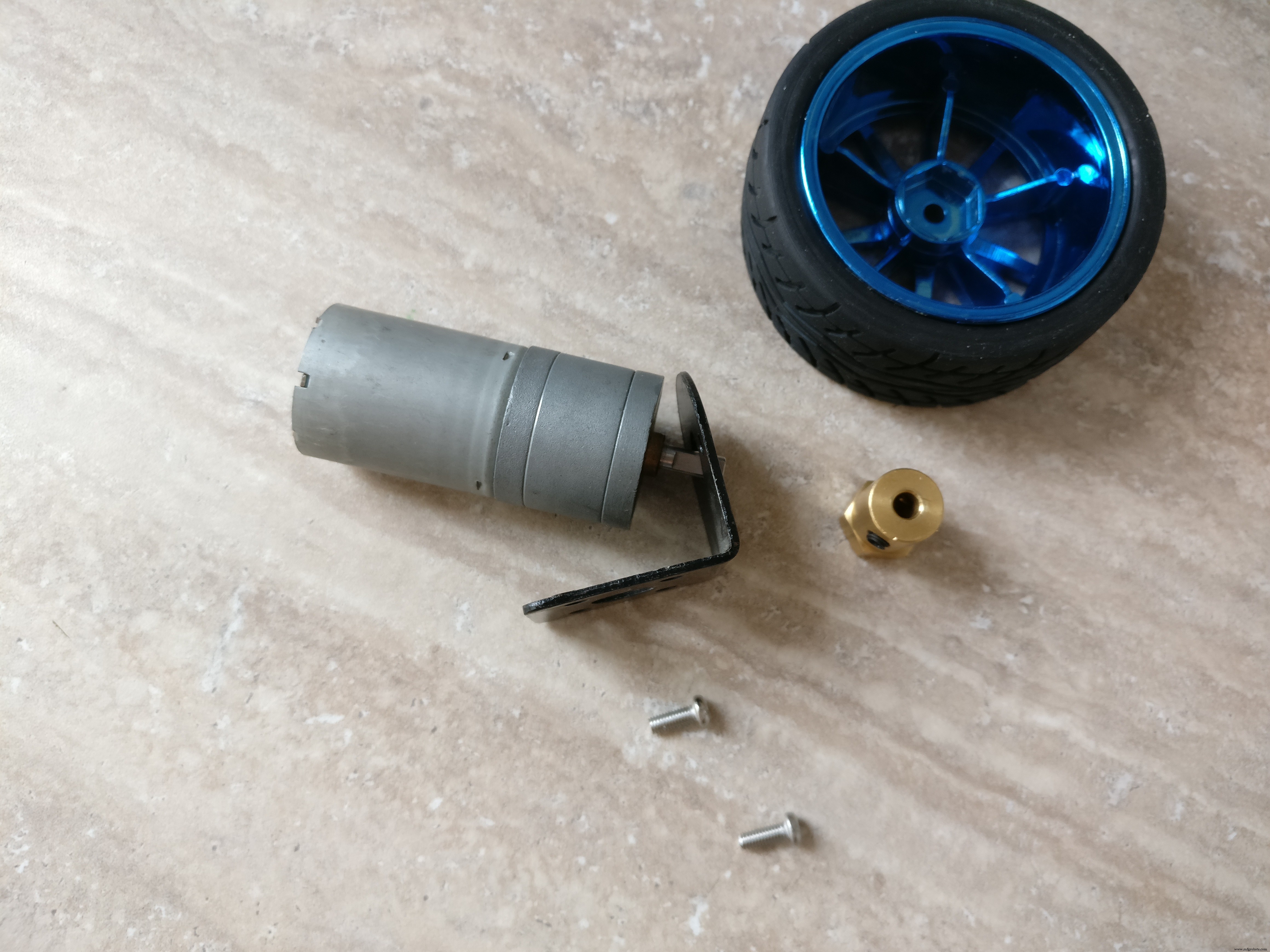
プレキシガラスまたは硬質プラスチックからロボットを構築します。両方を使用しましたが、好きなものを選択できます。
ベースプレート DCエンジンはベースプレート上で18x 13 cmになり、金属製のブラケットのナットとボルトで取り付けられます。 Hブリッジは、床に面したプレートの中央に取り付けられます。後輪は2cmの六角形の金属スペーサー(片側オス片側メス)を使用して取り付けられます
上面の電子機器を接続するには、Hブリッジの近くに大きな穴が必要です。
上部 ロボットの1つは「L」字型の2つのプレートで構成され、1つは12 x 13 cm、もう1つは6.5 x 13cmになります。プラスチックプレートは一緒に接着されます。これらのプレートは、電子機器のカバー、ヘッドライトを取り付ける場所、およびラズベリーパイケースのサポートを提供します。上部は6cmの六角形の金属スペーサーを使用して下部から取り付けられます)
ステップ3:電子機器の構築 <図>
 <図>
<図> 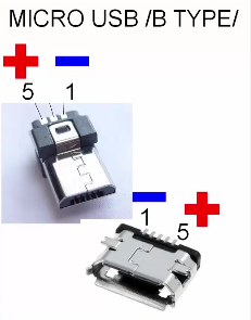 <図>
<図> 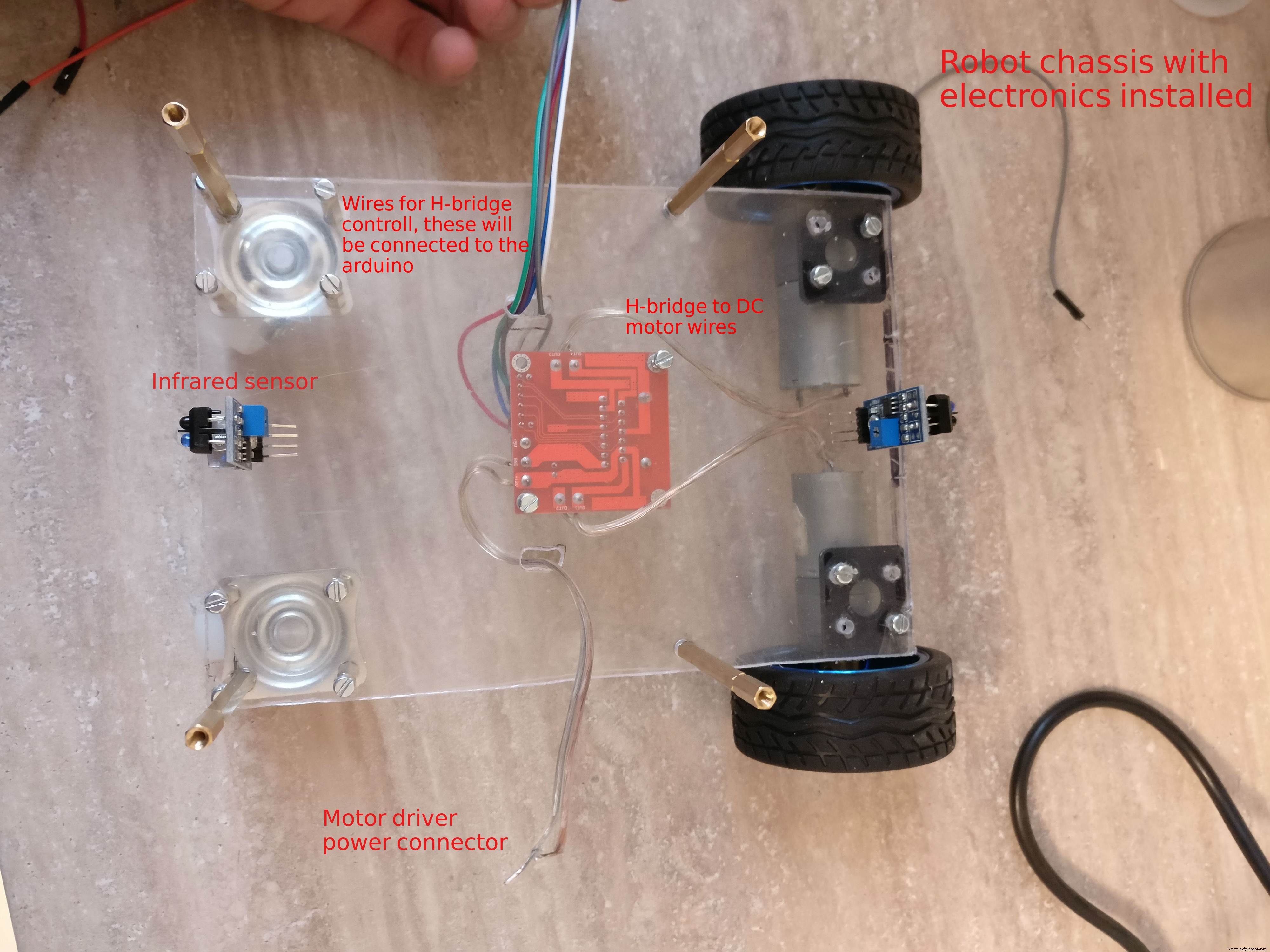 <図>
<図> 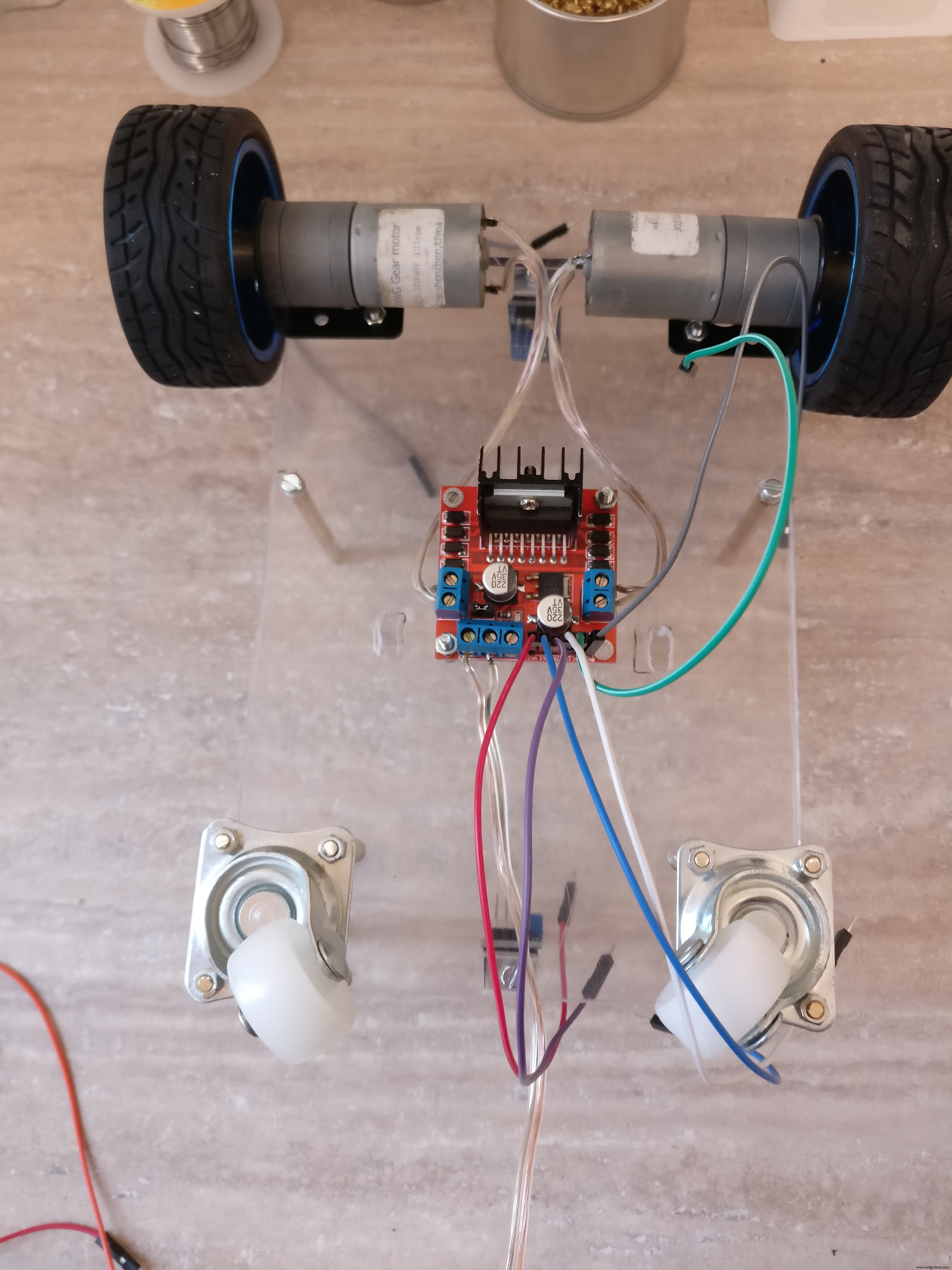 <図>
<図> 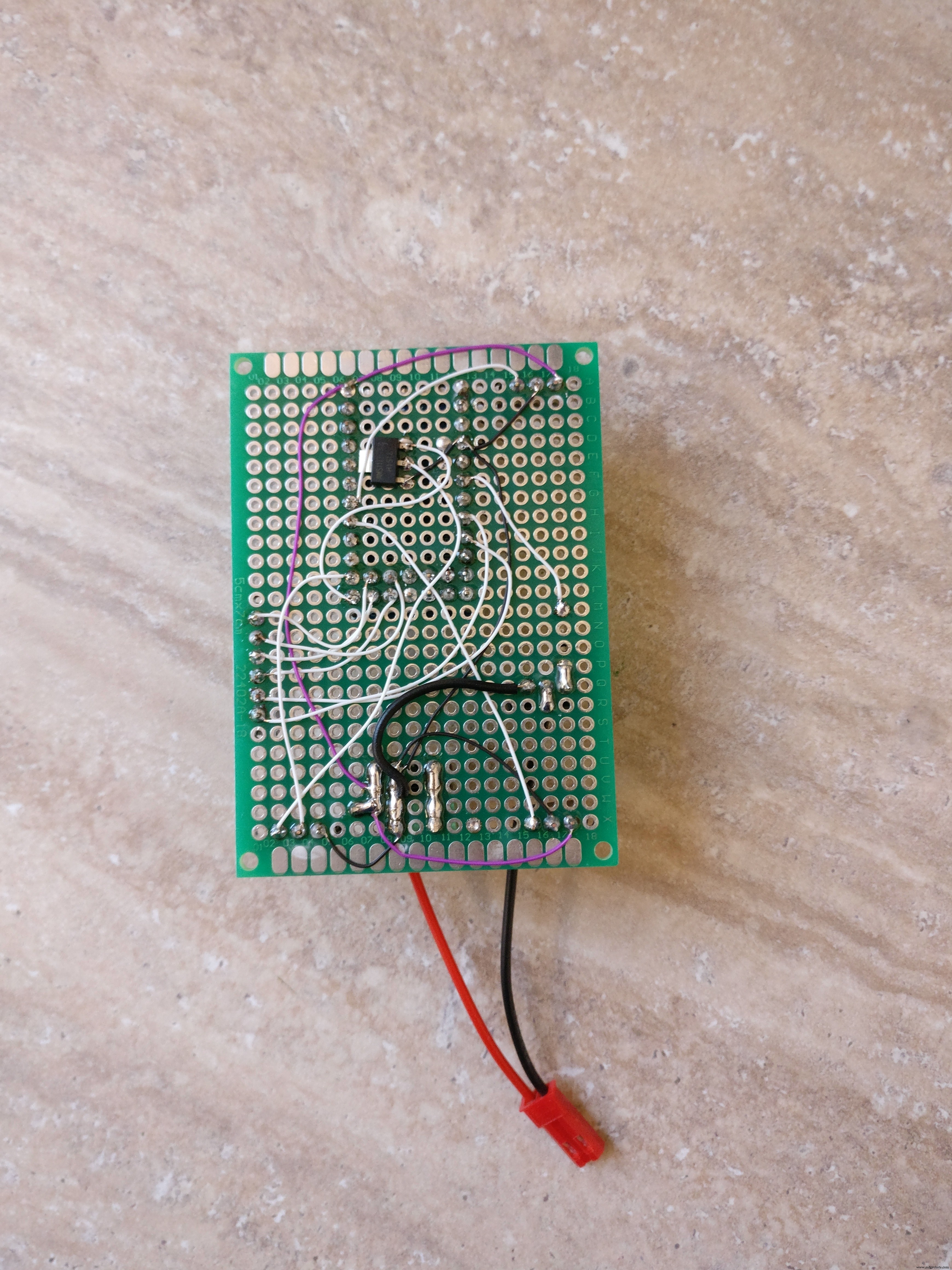 <図>
<図> 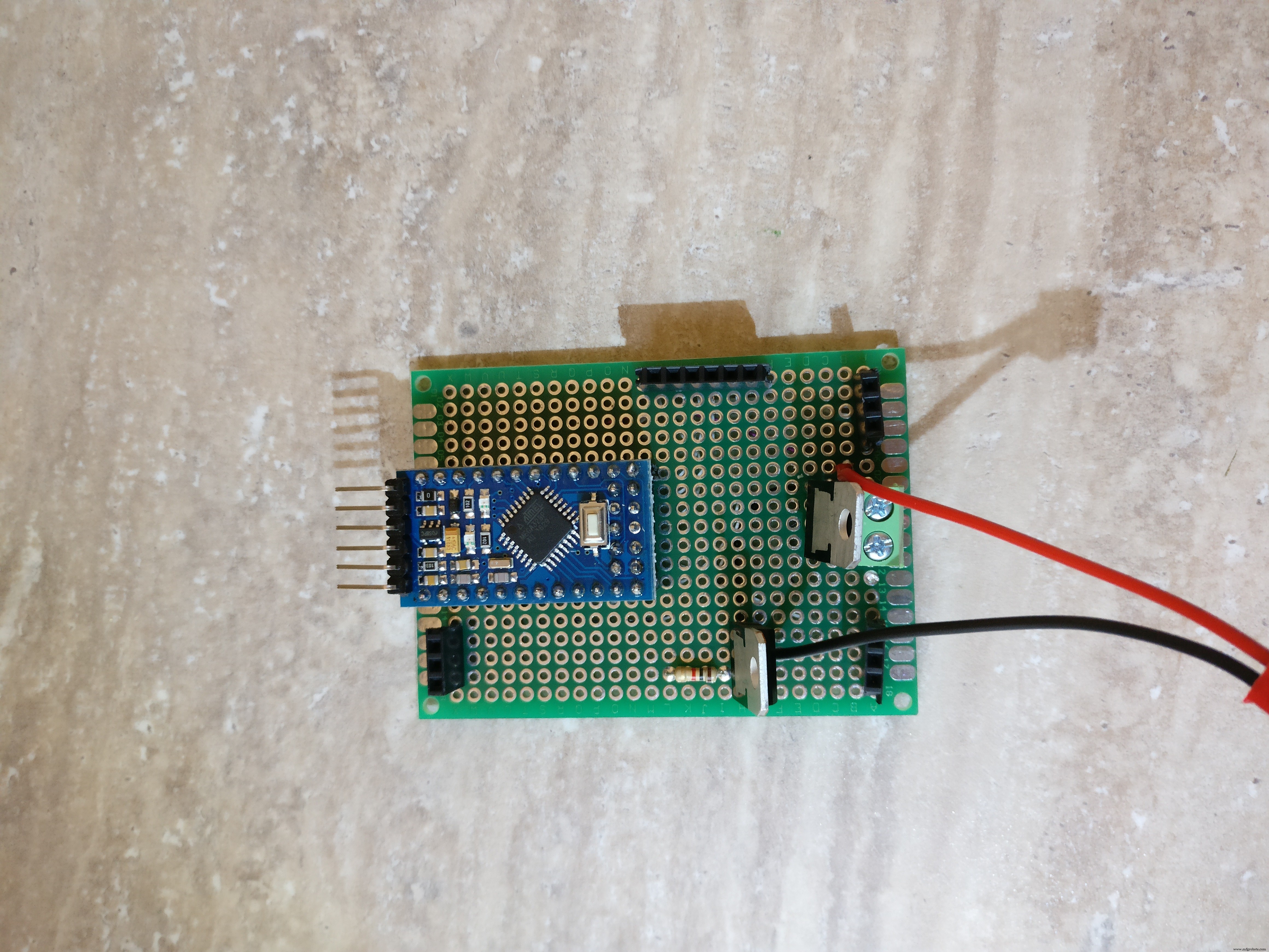 <図>
<図> 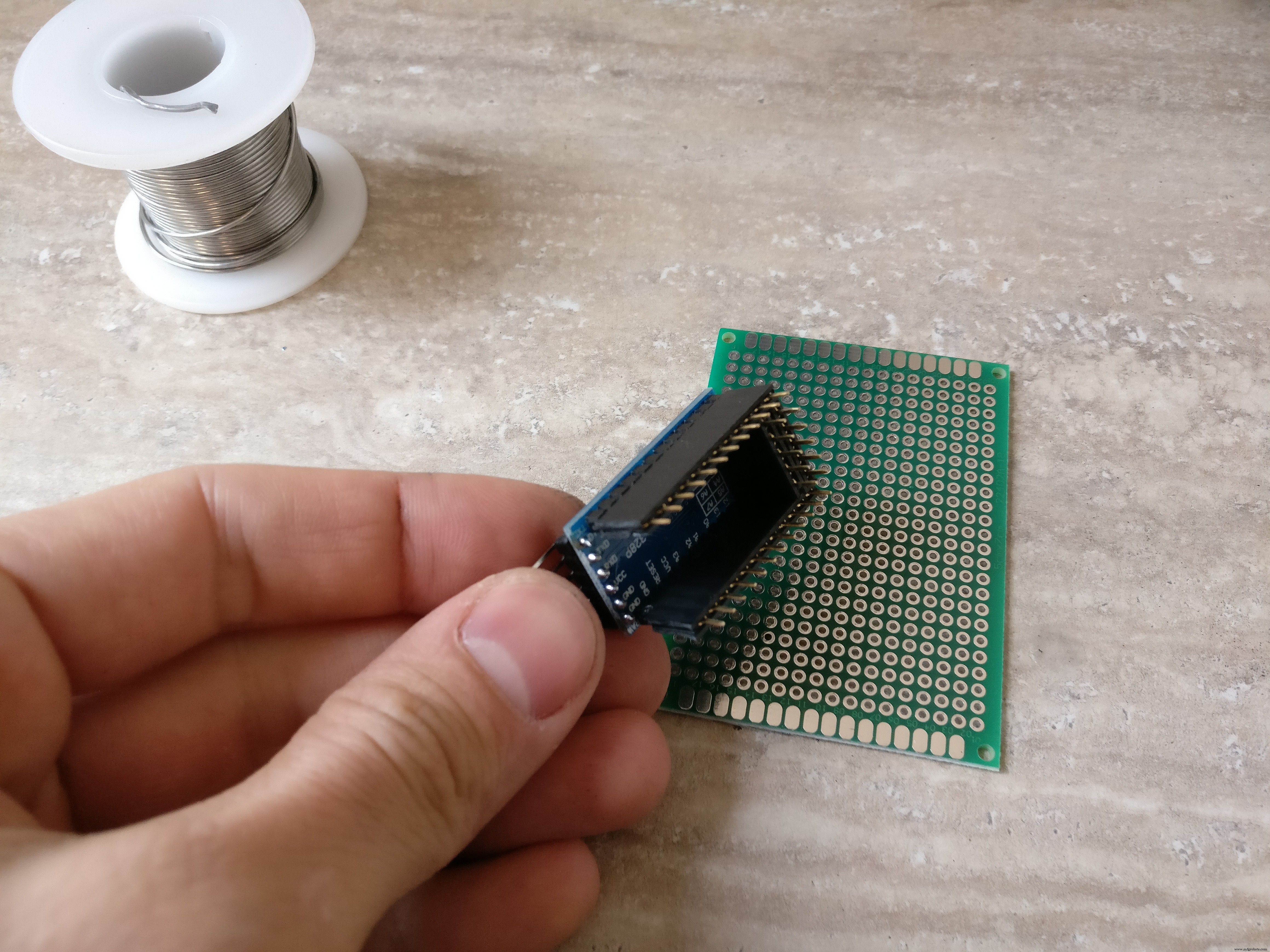 <図>
<図> 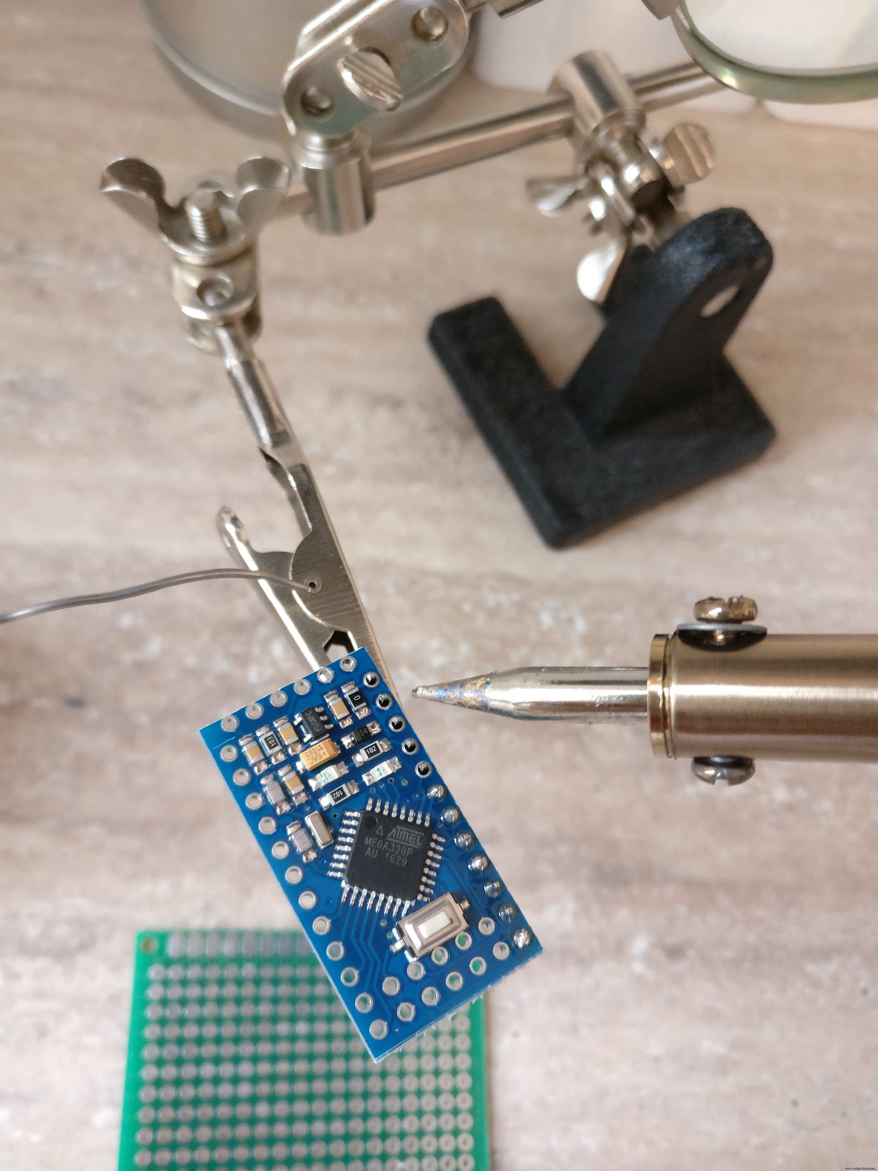 <図>
<図>  <図>
<図> 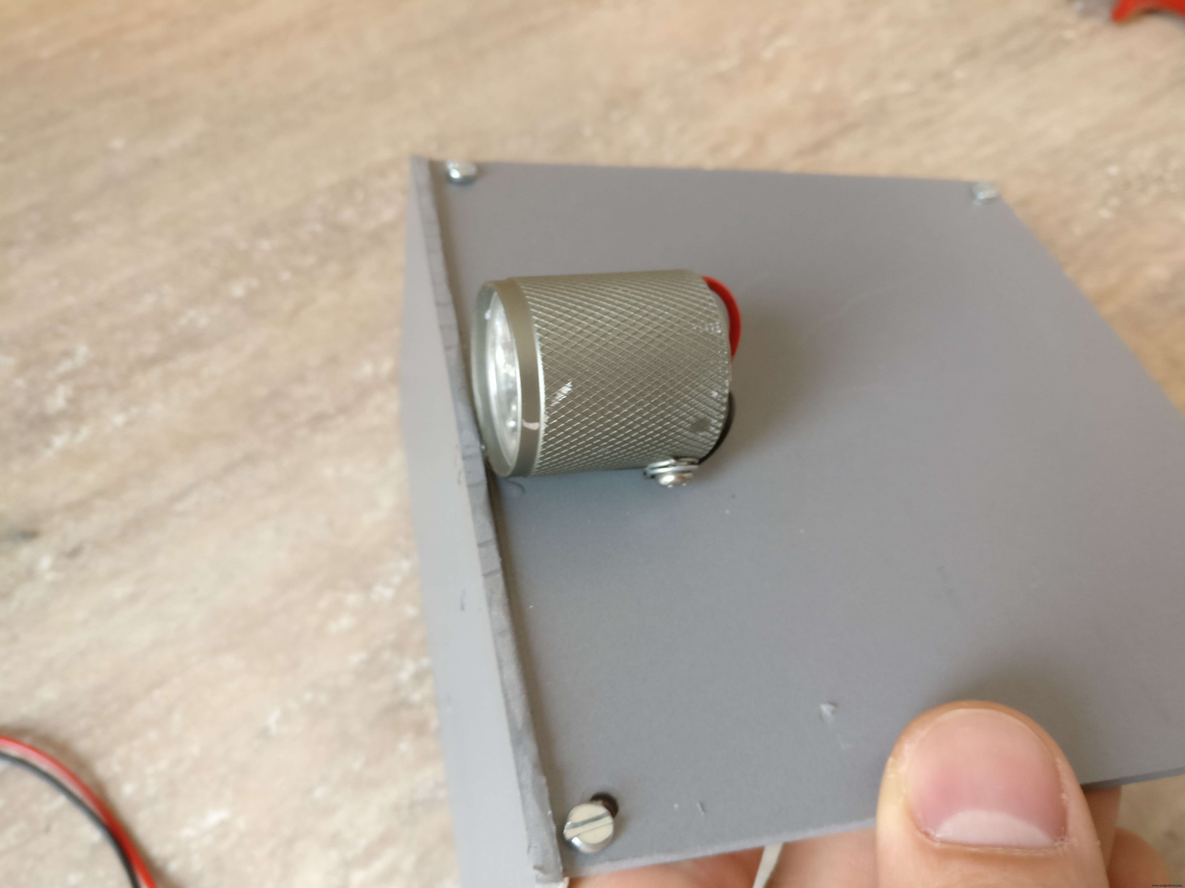 <図>
<図> 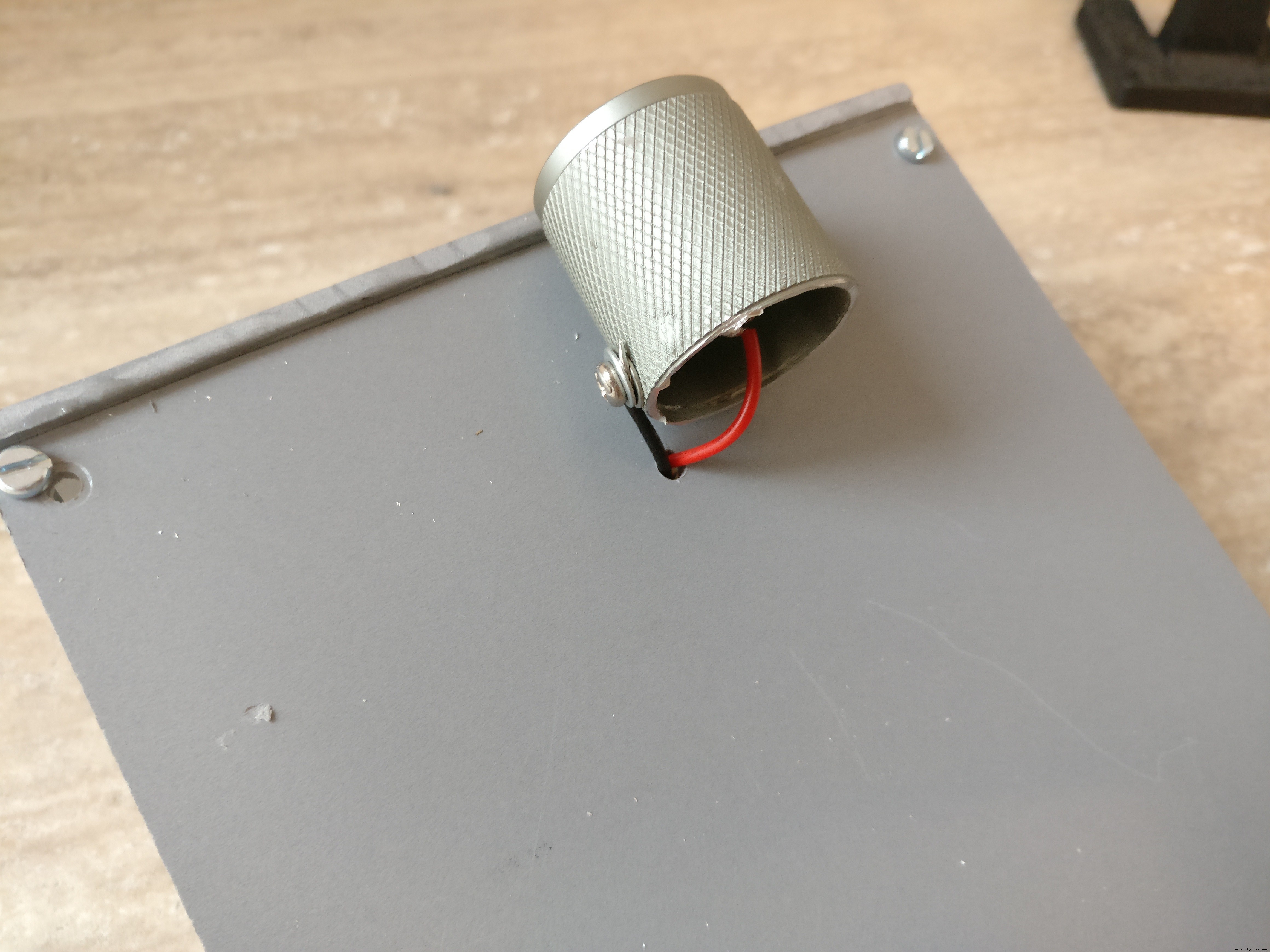 <図>
<図> 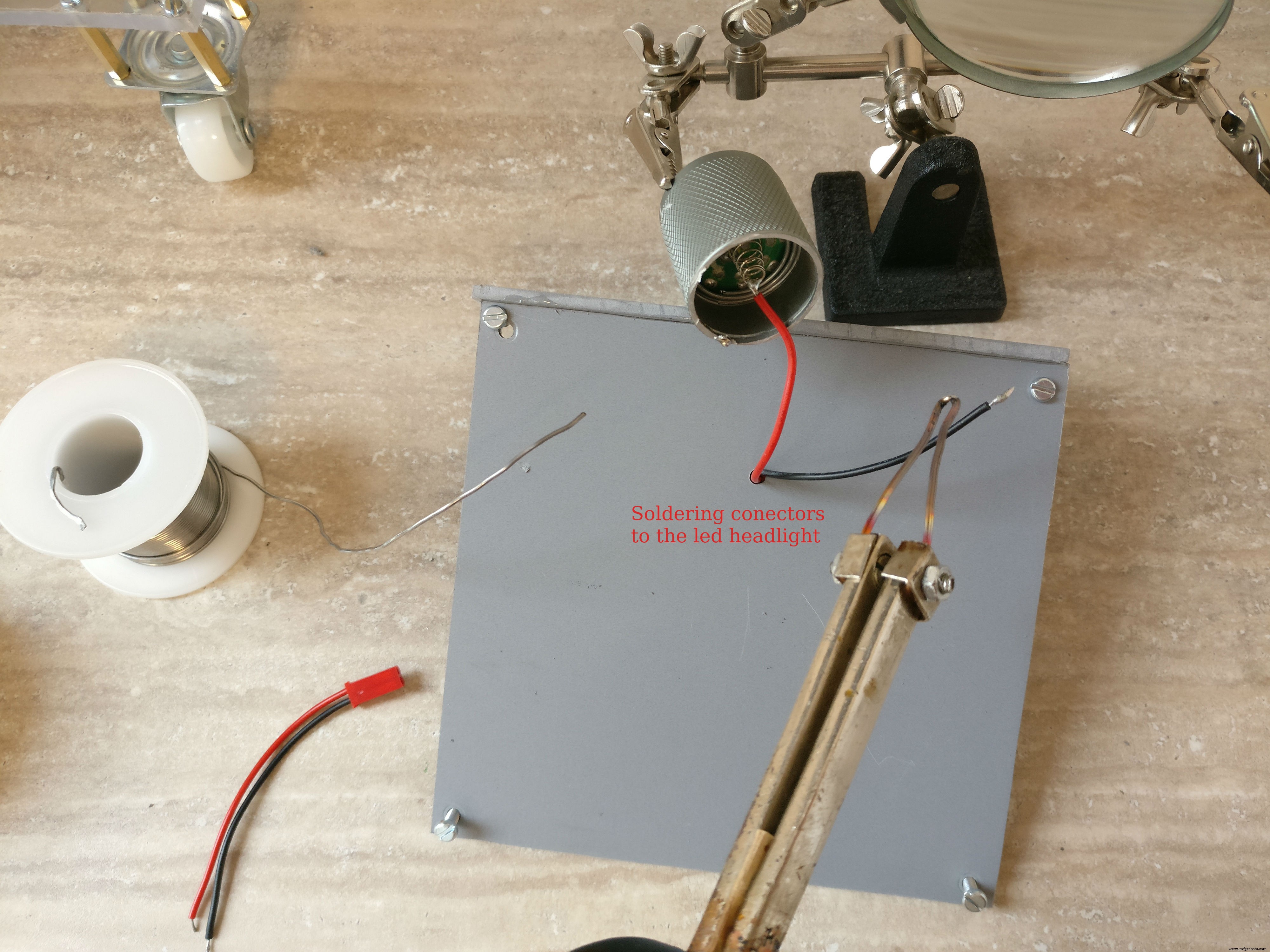 <図>
<図> 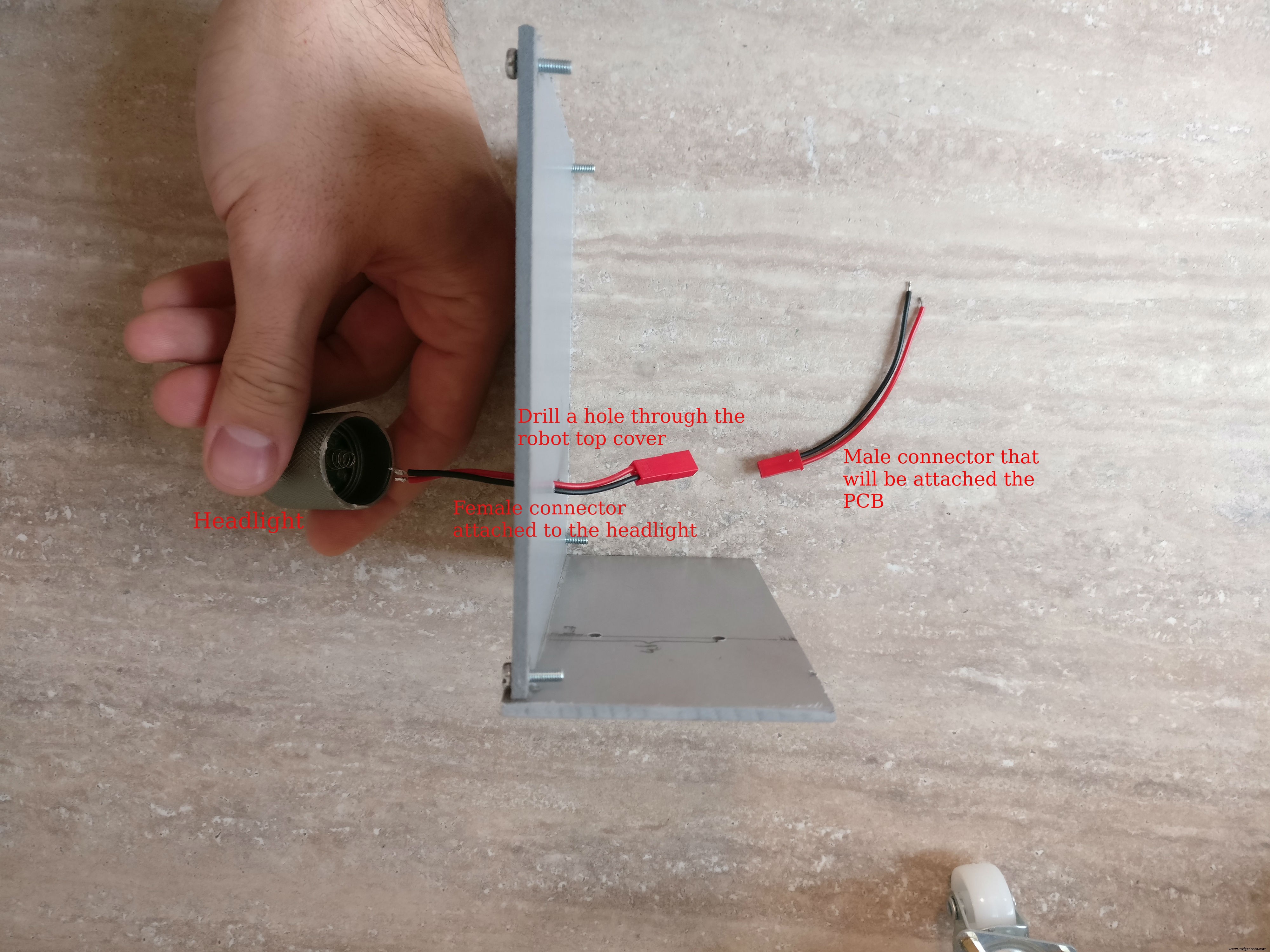 <図>
<図>  <図>
<図>  <図>
<図>  <図>
<図>  <図>
<図>  <図>
<図> 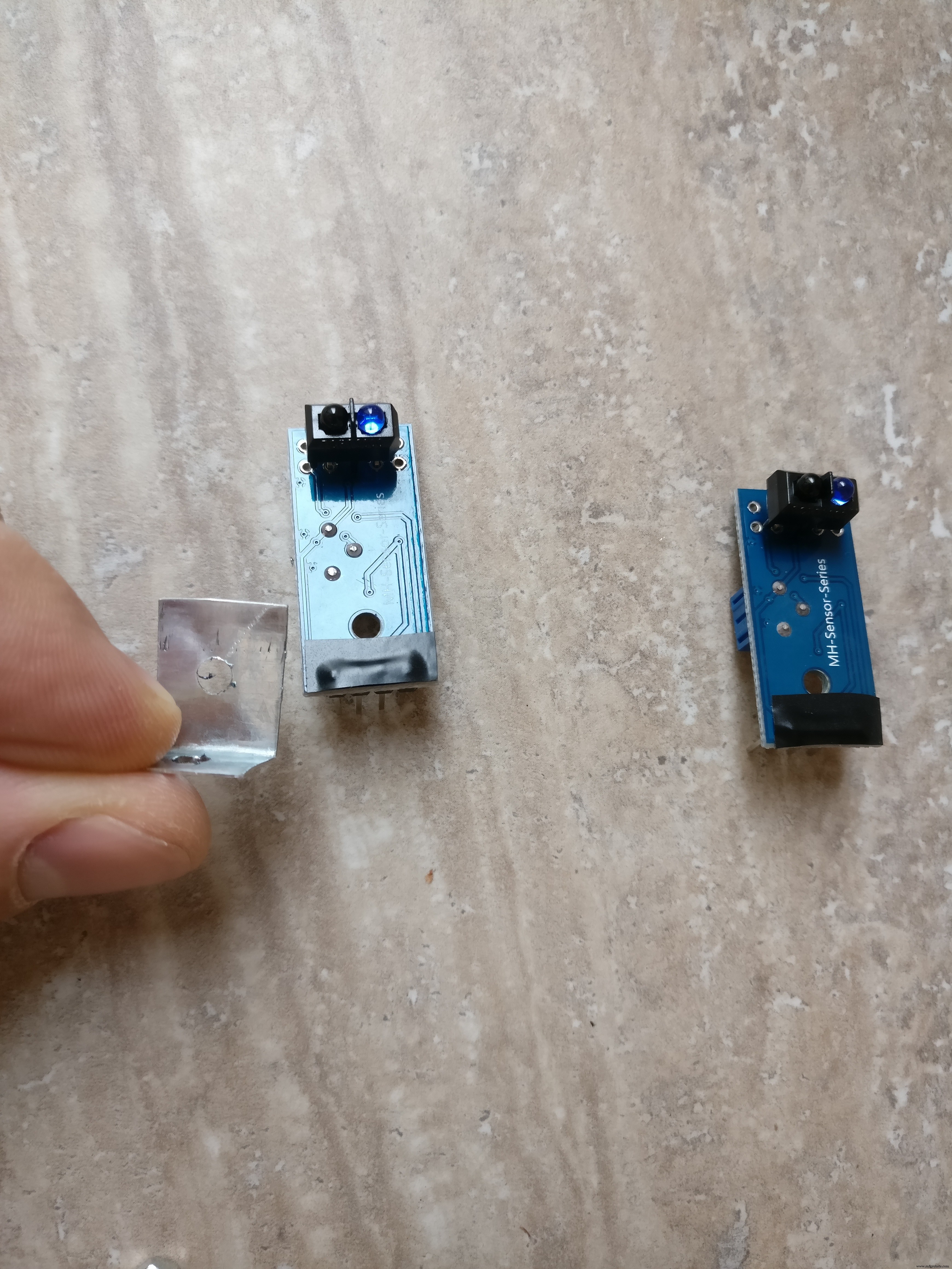 <図>
<図> 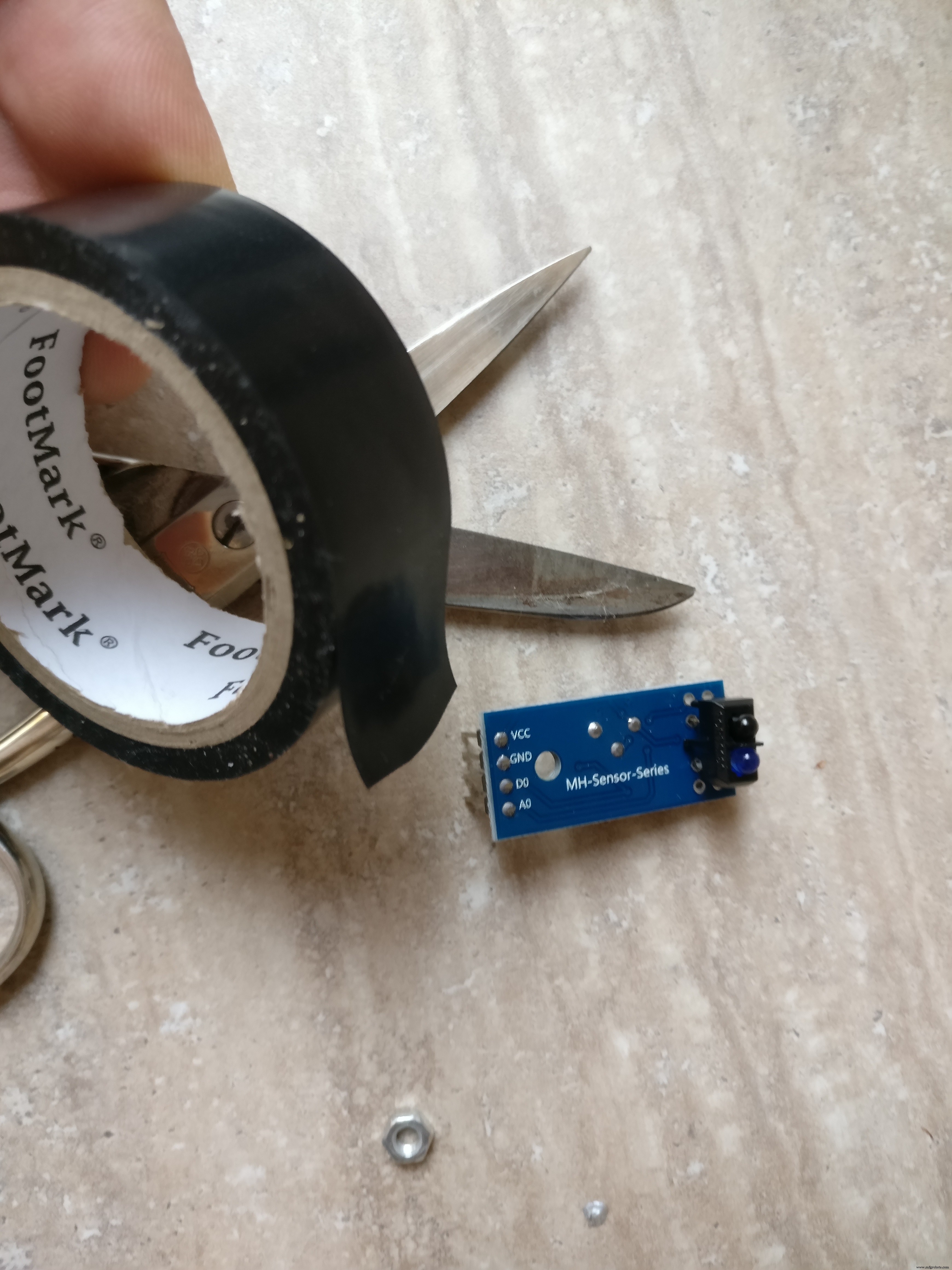 <図>
<図> 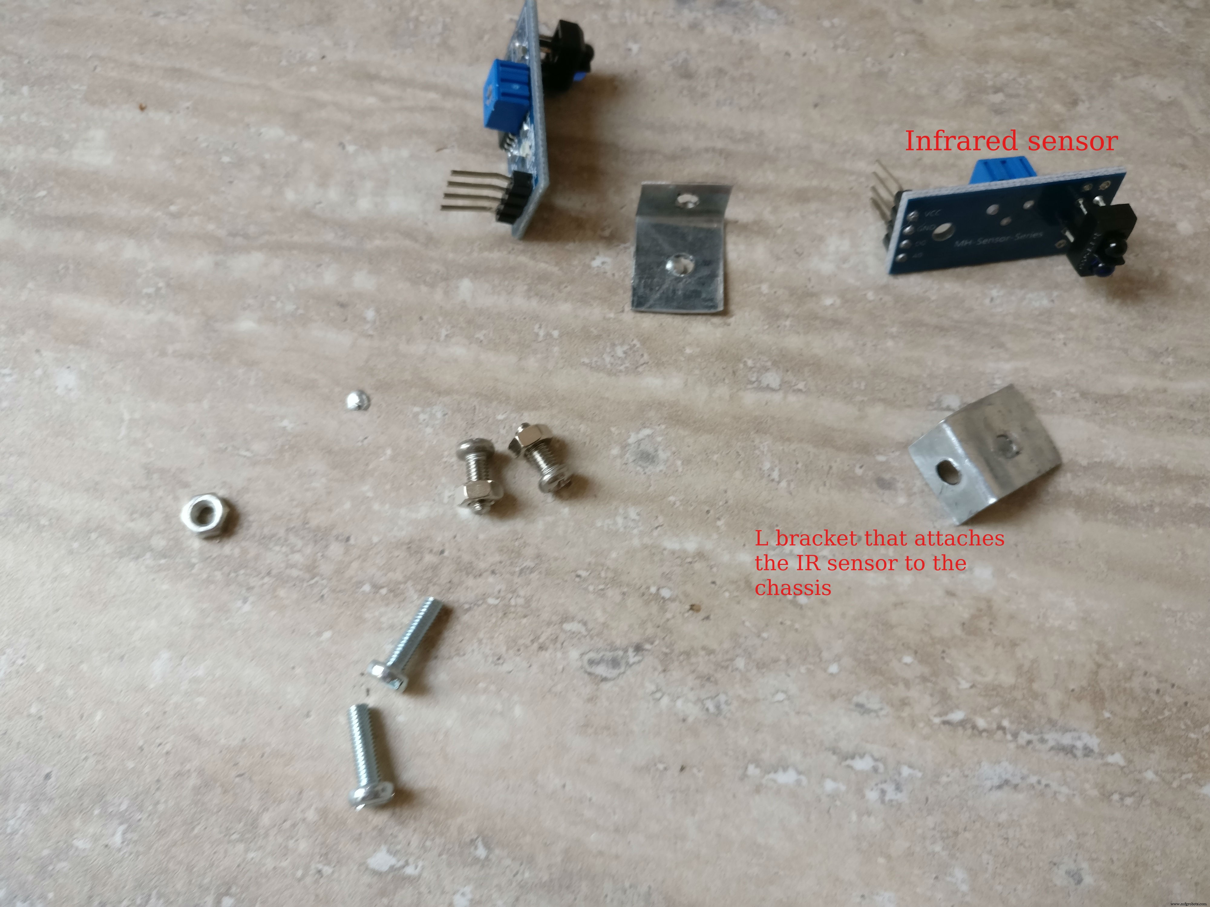 <図>
<図> 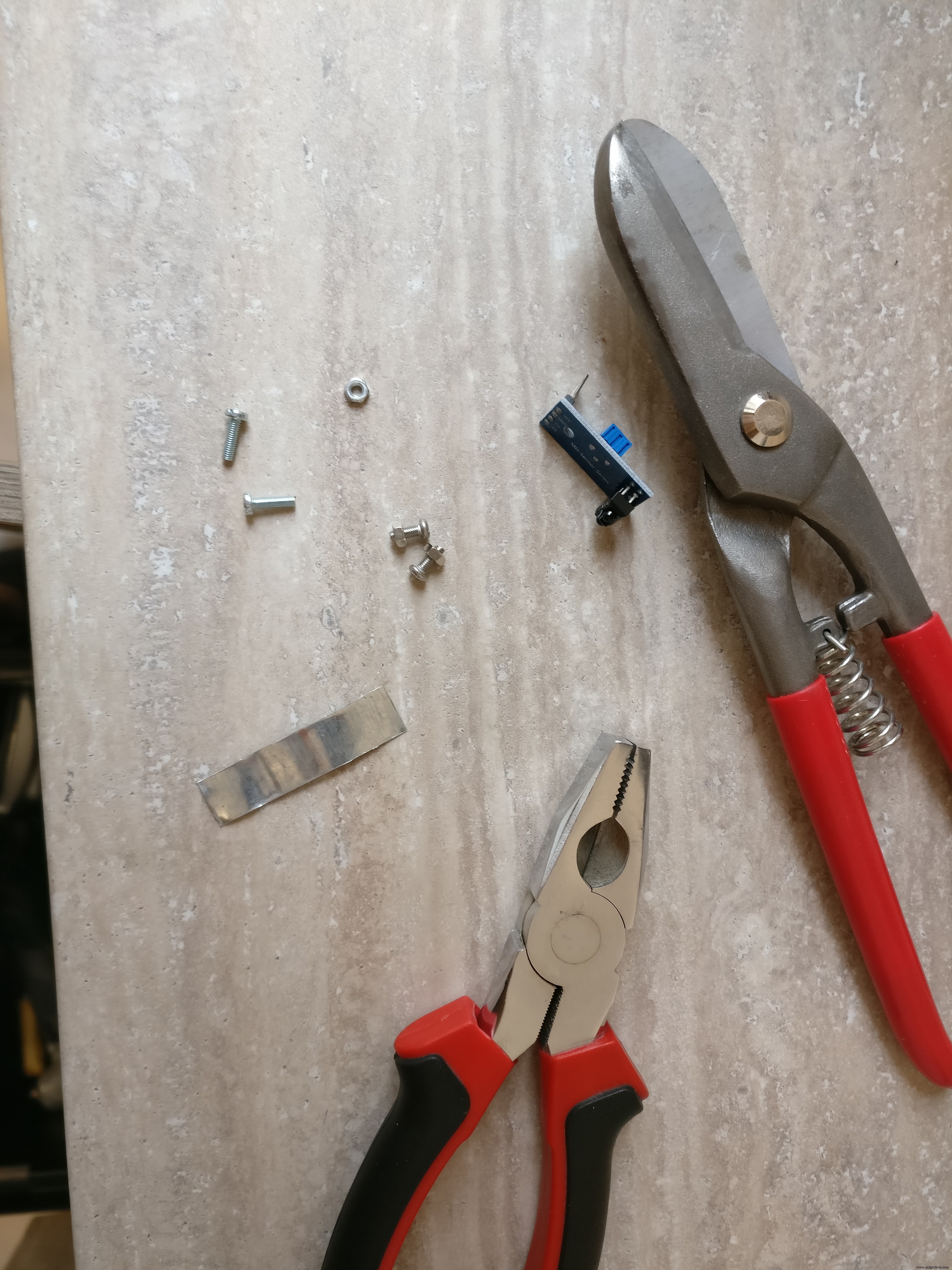 <図>
<図> 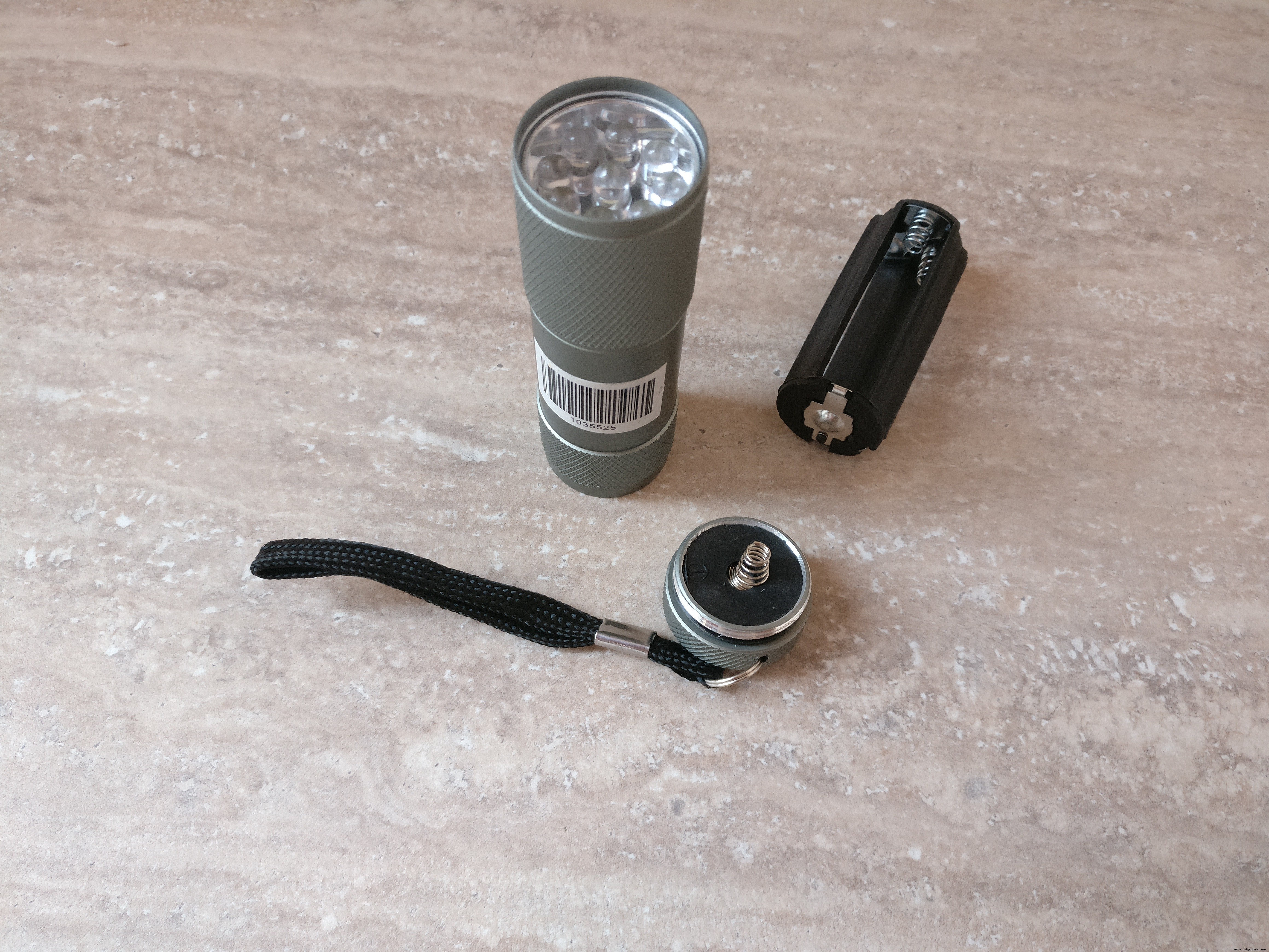 <図>
<図> 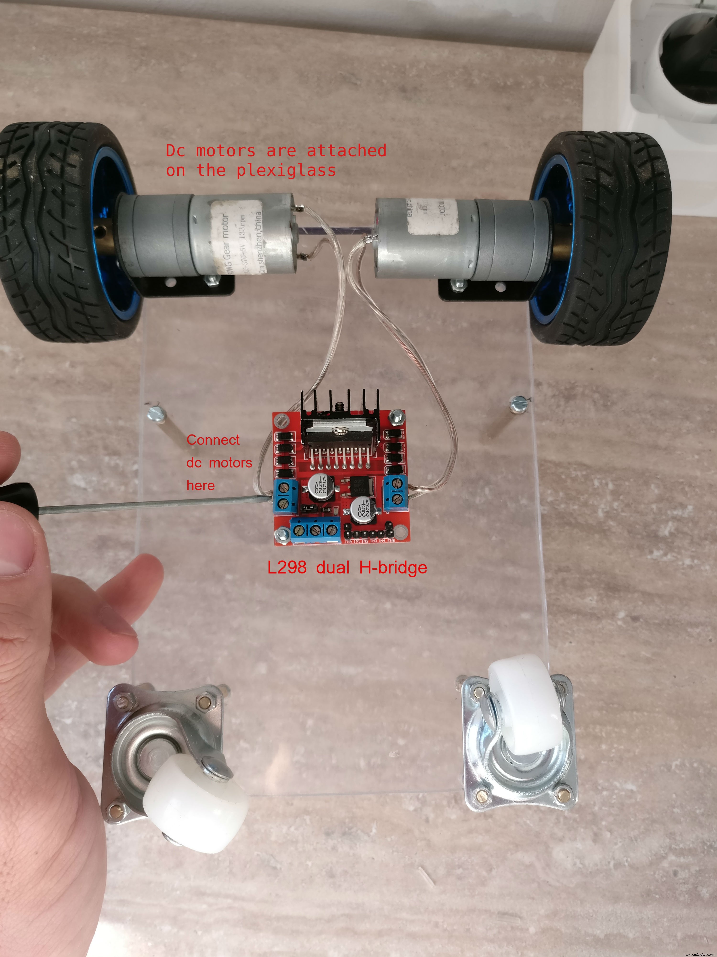 <図>
<図> 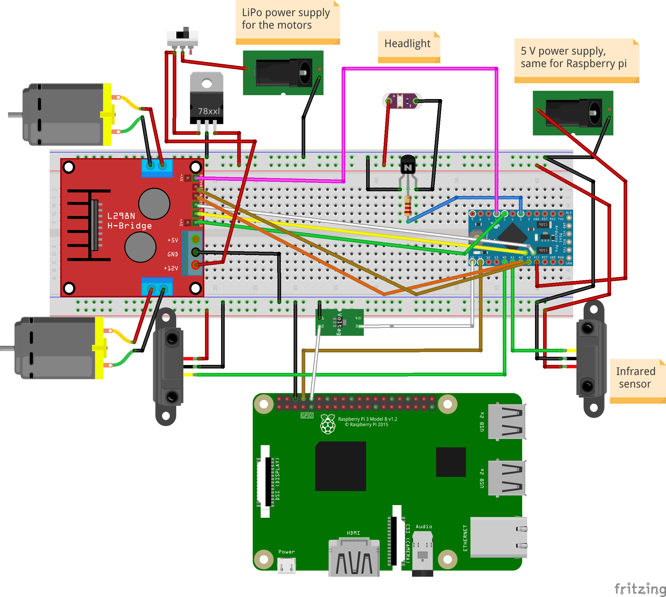
ピン配列(arduino):
LED懐中電灯:D3
左モーター:PWM(D5)、EN1、EN2(A4、A5)
右モーター:PWM(D6)、EN1、EN2(A3、A2)
赤外線センサー:前面(A0)、背面(A1)
ラズベリーパイ通信ピン:Tx:D11、Rx:D10
PCBの構築、アセンブリ
1。 最後のステップでは、ロボットの床側にHブリッジをすでに収容しました。また、2つの赤外線センサーをインストールする必要があります 1つは前に、もう1つは後ろにあります。小さな金属板を使用してシャーシに取り付けます。金属板は「L」字型になり、2つの穴があります。ナットとボルトを使用して、シャーシに取り付けます。センサーは、シャーシの中央に1つずつ前面に、もう1つは背面に配置されます。
2。 次にヘッドライト 一部、私はこれに5ボルトのLED懐中電灯を使用しました。 「ヘッド」部分だけを露出させるヘッドライトをカットし、2本のワイヤーをはんだ付けして電力を供給しました。次に、ロボットの上部の中央にヘッドライトを接着し、ヘッドライトの近くにドリルで穴を開け、ケーブルを穴に通して、小さなメスの2線式コネクタをはんだ付けしました。
3。 ラズベリーパイケースの組み立て。 ラズベリーパイ、パイカメラ、4 GB以上のメモリカード、パイカメラコネクタが必要です。最新のRaspianがインストールされたカードを挿入し、piカメラコネクタを使用してラズベリーpiに慎重に挿入し、カメラに挿入してからケースを閉じます。
Raspianオペレーティングシステムのインストール方法がわからない場合は、このリンクを確認してください。
カメラをインストールして有効にする方法の詳細については、この公式記事を確認してください。
4。 主要な電子部品を使用してPCBを構築します。 フリッツの回路図をfzz形式で写真として添付しました。電子機器の作り方の参考としてお使いいただけます。
はんだ付け手順:
a。 メスのPCBコネクタをカットします。マイクロコントローラ用の12ピンコネクタが2つ、5ピンコネクタが2つあり、IRセンサー用の3ピンコネクタが2つ、Hブリッジ用の6ピンコネクタとラズベリーパイ通信用のピンコネクタがあります。 (グラウンド、TX、RX) b。 すべてのコネクタを切断した後、PCBの背面にはんだ付けする必要があります
c。 KF301-2Pコネクタをはんだ付けします
d。 NPNトランジスタと対応する抵抗器をそのベースにはんだ付けします
e。 L7805CV5Vレギュレーターをはんだ付けします
f。 3.3ボルトレギュレーターをはんだ付けします arduinoからraspeberrypiTXラインまで
g。 オスのピンをarduinoprominiにはんだ付けします
h。 fritzigの回路図に従って、すべての赤(+)、黒(-)、および白(信号)の細いワイヤーをはんだ付けします
i。 懐中電灯用のブレッドボードにオスコネクタをはんだ付けします
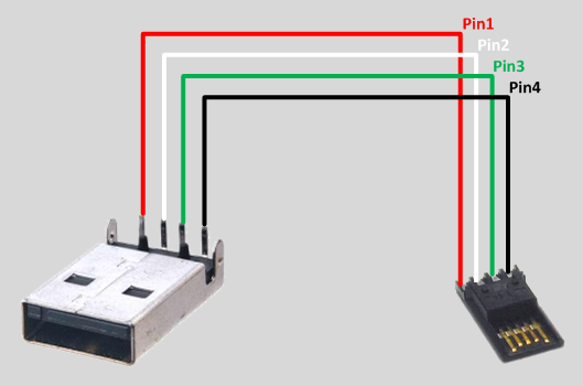
5。コネクタ
a。 5V USBバッテリーパックからラズベリーパイとarduinoへのコネクタを構築します。オスのUSBコネクタタイプA、オスのマイクロUSBコネクタの黒と赤のワイヤ、熱収縮チューブ、メスからメスのブレッドボードコネクタが必要です。最初にメス-メスコネクタを2つに切断します。これらの部品は、arduinoのネガティブおよびポジティブオスピンに入ります。タイプAのUSBコネクタは、マイクロUSBコネクタを使用してarduinoとラズベリーパイに電力を送信します。 USBチップのはんだ付けについては画像を確認してください。
b。 コネクタを作成します LiPoバッテリーを電子ボードに接続するには、XT-60メスLiPoコネクター、赤と黒のワイヤー、熱収縮チューブ、および10Aを処理できる小さなスイッチが必要です。黒のワイヤーはXT-60から直接接続されます。電子ボード(KF301-2Pプラグインスクリューコネクタ)に、赤いワイヤーが小さなスイッチを介して接続されます
c。 ロボットの2つのIRセンサーを、メス-オスのブレッドボードコネクタを使用して、PCB上の対応するメスコネクタに接続します
d。 オス-メスブレッドボードコネクタを使用して、HブリッジをPCBへの6ピンメスコネクタに接続します
e。 モーターのプラス端子とマイナス端子をHブリッジに接続します
f。 Hブリッジ主電源をPCBのKF301-2Pプラグインネジコネクタに接続します
6。 arduinoをPCBに配置する前に、虫眼鏡とマルチメーターを使用してすべてを再確認してください
ステップ4:Arduinoコード
最初に重要な質問に答える必要があります: Piを電子機器に直接接続するのではなく、中間のarduino層が存在する必要があるのはなぜですか?
1。 よりモジュール化されているため、PIなしで別のプロジェクトでarduinoロボットを再利用できます
2。 安全のために、Pi(35 $)を交換するよりも3 $ arduino prominiを交換する方が安価です
3。 piのようにオペレーティングシステムに邪魔されないarduinoなので、モーターのPWM制御を実装し、フロントセンサーとバックセンサーを1秒間に数回ポーリングする方が効率的です。
4。 Pythonスクリプトでエラーが発生した場合、ロボットは永久にバッテリーを消耗し、監視されていない場合はバッテリーを損傷したり発火したりする可能性があります。arduinoスケッチでは、オペレーティングシステムに依存しないため、より信頼性が高くなります。
5。 分離されたシステムのデバッグは簡単です
わかりました。Whyの部分について説明しました。arduinoのスケッチについて少し説明します。基本的に2つのことを行います:
1。 受信 モーターとライトのコマンド シリアルラインからモーターを駆動するか、ライトを切り替えます
例:
* " M:-25:16; "は(-25左)、(16パワー)を意味し、左モーターが17%、右モーターが32%に変換され、前方に移動します*" M:44:19; 「は(右に44)と(19のパワー)を意味します:左モーター38%、右モーター5%、前方方向
* " L:1; 「」はライトを意味し、「 L:0 「消灯
2。 赤外線センサーをポーリングします ロボットの背面と前面から、距離に関するデータを送信します シリアルライン経由
まず、このライブラリをダウンロードしてインストールする必要があります:
メインコードはここのgithubリポジトリにあります。または、下からコピーして貼り付けることもできます。
FTDIアダプターを使用してコードをarduinoにアップロードします。これで、ロボットにコマンドを与えて動作を確認できます。これには、2番目のシリアルラインを接続し、モーターまたはライトを送信するだけです。これを行う1つの方法は、HC-05などのBluetoothモジュールを使用し、Bluetoothアプリケーションを使用して電話に接続することです。次に、「L:1」のようなシリアルコマンドを指定します
// TextMotorCommandsInterpretterのソース: "https://github.com/danionescu0/arduino/tree/master/libraries/TextMotorCommandsInterpretter" #include #include const char MOTOR_COMMAND ='M'; const char LIGHT_COMMAND ='L'; / ** *モーターコマンドが有効になる時間(ミリ秒)*着信モーターコマンドはmaxDurationForMottorCommandの間持続します*別のモーターコマンドによってリセットされない場合* / const long maxDurationForMottorCommand =300; //この値を調整して、ロボットの速度を制限しますconst byte maxPwmValue =230; //連続する距離の送信間の長さ(ミリ秒)const longtransmitingInterval =500; const int maxObstacleDetection =1000; //アナログ読み取り最大検出値constint minObstacleDetection =500; //アナログ読み取り最小検出値constbyte FLASH_PIN =3; constバイトRIGHT_MOTOR_PWM_PIN =5; const byte RIGHT_MOTOR_EN1_PIN =A4; const byte RIGHT_MOTOR_EN2_PIN =A5; constバイトLEFT_MOTOR_PWM_PIN =6; constバイトLEFT_MOTOR_EN1_PIN =A3; constバイトLEFT_MOTOR_EN2_PIN =A2; constバイトFRONT_DISTANCE_SENSOR =A0; constバイトBACK_DISTANCE_SENSOR =A1; SoftwareSerial masterComm(11、10); // RX、TX TextMotorCommandsInterpretter motorCommandsInterpretter(-50、50、-50、50);文字列currentCommand; long lastCheckedTime; long lastTransmitTime; boolean inMotion =false; void setup(){Serial.begin(9600); masterComm.begin(9600); masterComm.setTimeout(10); pinMode(FLASH_PIN、OUTPUT); pinMode(LEFT_MOTOR_PWM_PIN、OUTPUT); pinMode(LEFT_MOTOR_EN1_PIN、OUTPUT); pinMode(LEFT_MOTOR_EN2_PIN、OUTPUT); pinMode(RIGHT_MOTOR_PWM_PIN、OUTPUT); pinMode(RIGHT_MOTOR_EN1_PIN、OUTPUT); pinMode(RIGHT_MOTOR_EN2_PIN、OUTPUT); lastCheckedTime =millis(); lastTransmitTime =millis(); } void loop(){if(masterComm.available()> 0){currentCommand =masterComm.readString(); processCommand(); } if(inMotion &&millis()-lastCheckedTime> maxDurationForMottorCommand){stopMotors(); } if(millis()-lastTransmitTime> TransmittingInterval){lastTransmitTime =millis(); masterComm.print(getObstacleData()); Serial.print(analogRead(BACK_DISTANCE_SENSOR)); Serial.print( "---"); Serial.println(getObstacleData()); } / *デバッグ用motorCommandsInterpretter.analizeText( "M:-14:40;"); Serial.write( "Left =="); Serial.println(motorCommandsInterpretter.getPercentLeft()); Serial.write( "Right =="); Serial.println(motorCommandsInterpretter.getPercentRight()); delay(10000); * /} String getObstacleData(){int frontDistance =analogRead(FRONT_DISTANCE_SENSOR); int backDistace =analogRead(BACK_DISTANCE_SENSOR); frontDistance =map(frontDistance、maxObstacleDetection、minObstacleDetection、0、10); backDistace =map(backDistace、maxObstacleDetection、minObstacleDetection、0、10); return String( "F =" + String(frontDistance)+ ":B =" + String(backDistace)+ ";"); } void processCommand(){switch(currentCommand.charAt(0)){case(MOTOR_COMMAND):steerCar();壊す;ケース(LIGHT_COMMAND):toggleLight(currentCommand.charAt(2));壊す; }} void steerCar(){motorCommandsInterpretter.analizeText(currentCommand); floatpercentLeftMotor =motorCommandsInterpretter.getPercentLeft(); floatpercentRightMotor =motorCommandsInterpretter.getPercentRight(); Serial.write( "Left ="); Serial.println(percentLeftMotor); Serial.write( "Right ="); Serial.println(percentRightMotor); setMotorsDirection(motorCommandsInterpretter.getDirection()); analogWrite(LEFT_MOTOR_PWM_PIN、percentLeftMotor * maxPwmValue); analogWrite(RIGHT_MOTOR_PWM_PIN、percentRightMotor * maxPwmValue); inMotion =true; lastCheckedTime =millis(); } void setMotorsDirection(boolean forward){if(forward){digitalWrite(LEFT_MOTOR_EN1_PIN、HIGH); digitalWrite(LEFT_MOTOR_EN2_PIN、LOW); digitalWrite(RIGHT_MOTOR_EN1_PIN、HIGH); digitalWrite(RIGHT_MOTOR_EN2_PIN、LOW); } else {digitalWrite(LEFT_MOTOR_EN1_PIN、LOW); digitalWrite(LEFT_MOTOR_EN2_PIN、HIGH); digitalWrite(RIGHT_MOTOR_EN1_PIN、LOW); digitalWrite(RIGHT_MOTOR_EN2_PIN、HIGH); }} void stopMotors(){Serial.println( "モーターの停止"); analogWrite(LEFT_MOTOR_PWM_PIN、0); analogWrite(RIGHT_MOTOR_PWM_PIN、0); inMotion =false; } void tokenLight(char command){Serial.println( "Toggle light"); if(command =='1'){digitalWrite(FLASH_PIN、HIGH); } else {digitalWrite(FLASH_PIN、LOW); }}
ステップ5:RaspberryPiプロジェクトと依存関係のインストールと構成
どのように機能しますか:
<図>
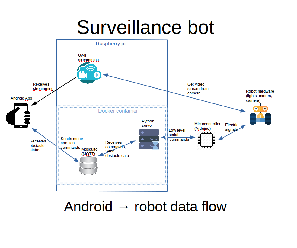
添付の画像に、上記で説明しようとしていることの図が表示されます。
a。 Androidアプリは、Webビュー内のuv4lストリーミングを表示します。 uv4lプロセスはラズベリーパイで実行され、カメラからのビデオ入力をキャプチャしてストリーミングします。多くの機能を備えた素晴らしいツールです
b。 Androidアプリ内のコントロールを使用すると、ライトとエンジンのコマンドがMQTTサーバーに発行されます
c。 ラズベリーパイのDockerコンテナ内のPythonサーバーは、MQTTコマンドをリッスンし、シリアルインターフェイスを使用してarduinoに渡します。 arduinoボードはモーターとライトを制御します。
d。 arduinoはロボットの前後の距離を感知し、シリアルインターフェースを介してPythonサーバーにデータを送信します。PythonはそれらをMQTTに転送し、Androidインターフェースによって取得されてユーザーに表示されます
最初 Raspberry piに完全にインストールおよび構成されたRaspbianが必要であり、カメラは精神的に接続および構成されている必要があります。また、すべての構成はsshを使用して行われるため、構成することをお勧めします。
ここでは基本的なことをすべて網羅することはできませんが、必要に応じて次のリンクを試してください。
Raspbianオペレーティングシステムのインストール方法がわからない場合は、このリンクを確認してください。カメラをインストールして有効にする方法の詳細については、この公式記事を確認してください。
Raspbianでsshを設定する方法については、これを確認してください。
Wi-Fiの外部からAndroidアプリを使用してロボットを制御する場合は、Wi-Fiルーターでのポート転送を検討する必要があります。そうしないと、Wi-Fi内でのローカルIPアドレスの使用が制限されます。
ラズベリーパイのローカルIPアドレスを確認するには、「ifconfig」を使用します。
ifconfig ......... eth0 Link encap:Ethernet HWaddr b8:27:eb:16:e7:ff inet6 addr:fe80 ::ff00:f22f:9258:b92b / 64スコープ:リンクアップブロードキャストマルチキャストMTU:1500メトリック:1 RXパケット:0エラー:0ドロップ:0オーバーラン:0フレーム:0 TXパケット:0エラー:0ドロップ:0オーバーラン:0キャリア:0衝突:0txqueuelen:1000RXバイト:0(0.0 B)TXバイト:0(0.0 B)........ wlan0 Link encap:Ethernet HWaddr 00:c1:41:00:10:f6 inet addr:192.168.0.102 Bcast:192.168.0.255マスク:255.255.255.0inet6アドレス:fe80 ::e1f4:5112:9cb2:3839/64スコープ:リンクアップブロードキャスト実行マルチキャストMTU:1500メトリック:1 RXパケット:1678396エラー:0ドロップ:0オーバーラン:0フレーム:0 TXパケット:381859エラー:0ドロップ:0オーバーラン:0キャリア:0衝突:0 txqueuelen:1000 RXバイト:259428527(247.4 MiB)TXバイト:187573084(178.8 MiB)..... wlan0 inet addr、この場合は「192.168.0.102」に関心があります
転送されるポート(デフォルト)は、uv4lの場合は9090、mosquittoの場合は1883です。インターネットプロバイダーのファイアウォールまたは他のいくつかのポートから禁止されていない場合は、このポートを同じ出力ポートに転送できます。
ポートフォワーディングは、ルーターごとに異なる方法で行われるものです。ここにいくつかのチュートリアルがあります。これは、Googleで検索することもできます。ポートフォワーディングyour_router_model "より関連性の高い結果を表示します。
前提条件:
a。 コマンドラインを使用してgitをインストールする
b。 ホームフォルダにgithubプロジェクトのクローンを作成します:
docker-compose.ymlでは場所が次のようにハードコーディングされているため、フォルダーの場所は重要です。/home / pi / robot-camera-platform:/ root / debug場所を変更する必要がある場合は、docker-composeの値を変更してください。あまりにも
git clone https://github.com/danionescu0/robot-camera-platform.git c。 piのシリアルコンソールを無効にします。その方法がわからない場合は、このリンクを確認してください
Uv4lストリーミングをインストールします:
chmod + x uv4l / install.sh chmod + x uv4l / start.sh sh ./uv4l/install.sh これが失敗した場合、またはuv4lの詳細を確認する必要がある場合は、このチュートリアルを確認してください。
構成:
a。 uv4l / start.sh を編集する ビデオストリーミングの次の側面を構成できます:パスワード、ポート、フレームレート、高さ、回転、およびその他のマイナーな側面
b。 config.pyを編集し、パスワードを置き換えます mosquittoサーバーに設定した自分のパスワードを使用する
c。 docker-container / mosquitto / Dockerfileを編集し、この行を置き換えます
RUN mosquitto_passwd -b / etc / mosquitto / pwfile user your_password 自分のユーザーとmosquittoのパスワードを使用する
d。 config.pyを編集し、シリアルポートを置き換えます ボーレートは自分で設定しますが、ボーレートは維持することをお勧めします。変更したい場合は、arduino-sketchでも編集することを忘れないでください
uv4lのインストールをテストしますa。 開始する:
sh ./uv4l/start.sh b。 次のアドレスのブラウザでテストします:http:// your_ip:9090 / stream
c。 やめて
sudo pkill uv4l
dockerとdocker-composeをインストールします
Dockerのインストールについて:https://www.raspberrypi.org/blog/docker-comes-to -...
docker-composeのインストールについて:https://www.raspberrypi.org/blog/docker-comes-to -...
再起動/起動時にサービスを自動開始
サービスを自動開始することで、sshを介して手動でログインし、すべてのサービスを手動でアクティブ化する必要がなくなります。これは、systemctlを使用して行います。
a。 Copy the files from systemctl folder in systemctl folder to /etc/systemd/system/
b. Enable services
sudo systemctl enable robot-camera.service sudo systemctl enable robot-camera-video.service c. Reboot
d. Optional, check status:
sudo systemctl status robot-camera.service sudo systemctl status robot-camera-video.service
Step 6:Configuring and Building the Android Application
We're all most done, in this step we're going to install the android application. These are all the prerequisites:
1。 Clone the github project:
git clone https://github.com/danionescu0/android-robot-camera The next steps involves setting up your environment, i'll just enumerate them and give a link to a specialized tutorial, in case you don't know how to do it.
2。 Enable developer options on your android phone. You can find out more here:https://developer.android.com/studio/debug/dev-opt...
3。 Download and install Android studio:https://developer.android.com/studio/index.html?ut... and this https://www.javaworld.com/article/3095406/android/...
4。 Import project :https://developer.android.com/studio/intro/migrate...
Now we're going to configure the the streaming and MQTT credentials:
5。 Edit ./app/src/main/values/passwords.xml and configure MQTT and streaming
The MQTT host should be something like:1883
The streaming host should be something like:
6。 Upload and run the application
Step 7:Using the Robot and Debugging <図>
 <図>
<図> 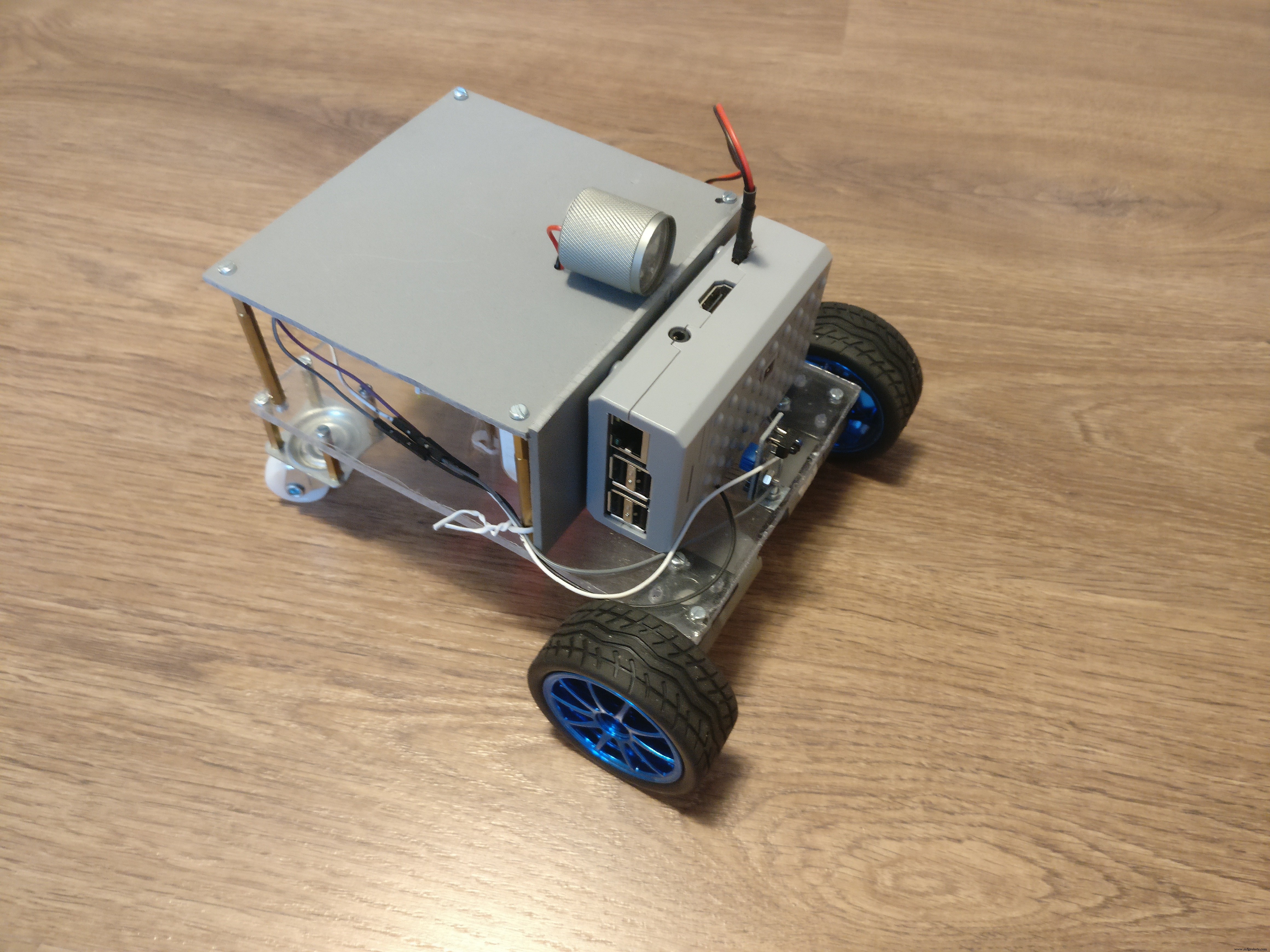 <図>
<図> 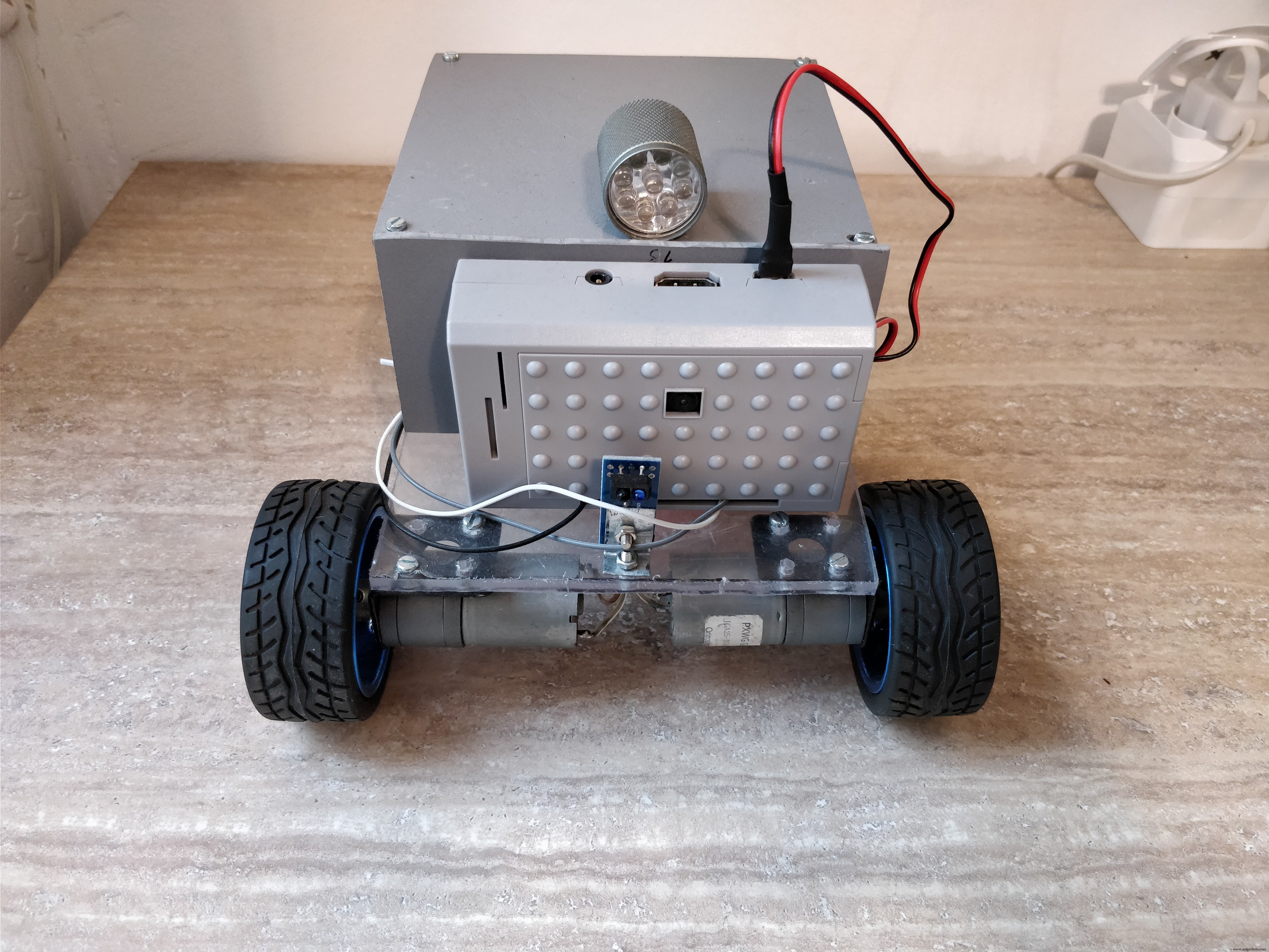
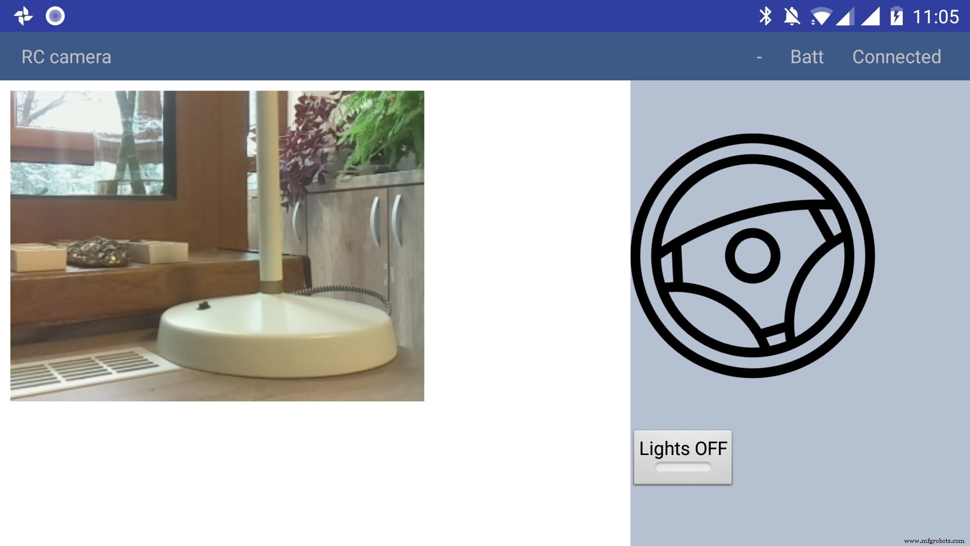
Using the app
The application has only a main screen, in the left of the screen the streamming image is displayed. On the right
there are the controls. The main control is a steering wheel, touch the steering wheel in the direction you wish the robot to move. Below the steering wheel there is a headlight button, touch it to toggle the light.
In the top right corner there is a text like :"- Batt Connected".
* First dash means no obstacles, if there is an obstacle in front or in the back of the robot it will be signaled with a small arrow pointing in front or in the back.
* The "Batt" status is not implemented yet.
* "Connected" means that MQTT server is connected so the robot can be used, the other possible value is "Disconnected"
Debugging can be done on multiple layers:
1。 On the arduino layer
- Connect the FTDI adapter to the second serial line to the laptop (RX to pin 11 and TX to pin 10) and issue motor commands and light commands to see if the robot responds to these commands
- Double check the connections, if the motors are moving backwards reverse the both motor wires, if one motor is moving backwards reverse the it's wires
- Check if the arduino is connected properly to the H-bridge, check this link for more information
2。 On the rasberry pi layer
- Check docker is running the two containers (mosquitto and python server)
pi@raspberrypi:~ $ docker ps CONTAINER ID IMAGE COMMAND CREATED STATUS PORTS NAMES 473a56da2230 dockercontainer_python-server "python /root/debu..." 9 months ago Up 4 hours dockercontainer_python-server_1 3e0b1933d310 robot-camera-mosquitto "/usr/bin/entry.sh..." 9 months ago Up 4 hours 0.0.0.0:1883->1883/tcp dockercontainer_mosquitto_1 - Check the processes are running on specified ports, you should look for 9090 (streamming) and 1883 (mosquitto)
pi@raspberrypi:~ $ netstat -nltp (Not all processes could be identified, non-owned process info will not be shown, you would have to be root to see it all.) Active Internet connections (only servers) Proto Recv-Q Send-Q Local Address Foreign Address State PID/Program name tcp 0 0 0.0.0.0:9090 0.0.0.0:* LISTEN - tcp 0 0 0.0.0.0:5900 0.0.0.0:* LISTEN - tcp 0 0 0.0.0.0:8080 0.0.0.0:* LISTEN - tcp 0 0 0.0.0.0:22 0.0.0.0:* LISTEN - tcp6 0 0 :::1883 :::* LISTEN - tcp6 0 0 :::5900 :::* LISTEN - tcp6 0 0 :::22 :::* LISTEN - - Check the serial port exists (it's the correct one) and it's specified in the project config.py
pi@raspberrypi:~ $ ls -l /dev/ttyS0 crw-rw---- 1 root dialout 4, 64 Jan 14 19:59 /dev/ttyS0 - Stop the docker process and manually connect to serial using picocom
Then issue motor and light commands directly to see if the robot responds
sudo systemctl start robot-camera.service picocom -b 9600 /dev/ttyS0 # now issue motor and light commands to test the robot - Check if the serial console is deactivated on the raspberry pi
- Check the streaming and MQTT are accessible outside the raspberry pi suing a mosquitto client (for MQTT) and checking the streaming in a web browser)
3。 Android application layer
- Check all the necessary steps to enable the phone into debugging mode (check this out)
- Make sure you've set up the passwords and endpoints correctly in the passwords.xml
- Check the streaming and MQTT are accessible outside the raspberry pi suing a mosquitto client (for MQTT) and checking the streaming in a web browser)
- See the top right corner of the app and check for "Connected"
- Use the android debugger to check for errors
Step 8:Other Use Cases, Extending the Code
Another use case is a object following robot .The robot will follow an object of a specific color and size threshold
Check above for the video.
Because this is out of scope of this tutorial i'll just give you some hints:
First install dependencies using pip, the installation process will be quite slow
sudo pip3 install -r /home/pi/robot-camera-platform/navigation/requirements.txt - make sure python 3.x is installed though
- In navigation/config_navigation.py you'll find:
hsv_bounds =( (24, 86, 6), (77, 255, 255) ) object_size_threshold =(10, 100) HSV means hue saturation value, and for our color object detection to work it has a lower and an upper bound, our object color will have to be in this range to be detected. Here you can find a visual HSV object threshold detector.
Object size threshold means the smallest and the highest object radius size (in percents from width) which will be considered a detection.
- install and configure VNC (more information of how to install VNC here)
- Run the object tracking script in VNC graphical interface in a terminal. This will enable you to view the video, with a circle drawn over it. The circle means that the object has been detected.
python3 object_tracking.py colored-object --show-video OR Run the object tracking script with no video output:
python3 object_tracking.py colored-object I think the main advantage of this platform is versatility , it can be adapted easily to other interesting usages, some of my ideas:
- Following a person by face recognition
- Patrolling and reporting movement
- Replace the wifi with a 3G modem and the robot can be controlled outside, maybe exploring dangerous zones
This being a very complex project i assume that there will be errors, i will appreciate if you ask me anything in the comments area.
If you like my project please my youtube channel for more interesting stuff.
コード
Android application
https://github.com/danionescu0/android-robot-cameraMain repository for arduino, python code
https://github.com/danionescu0/robot-camera-platform 回路図
sketch_nWf7cZeUWL.fzz Main repository for arduino, python code
The main repositoryhttps://github.com/danionescu0/robot-camera-platformAndroid application
https://github.com/danionescu0/android-robot-camera製造プロセス
- カメラ
- カメラレンズ
- MrRobot – Ubuntuモバイルアプリ対応のロボティクス(Raspberry Piとarduinoが関与)
- Roomberry Surveillance Robot:Roomba + Pi Zero + Camera
- ArduinoBluetooth制御の電動カメラスライダー
- NeoPixelリングでジャイロスコープを楽しむ
- Arduino、1Sheeld、Androidを使用したユニバーサルリモコン
- Arduinoゲームコントローラー
- Pixie:ArduinoベースのNeoPixel腕時計
- Arduinoによる音声認識と合成
- ArduinoPowerPointポインター