


ArduinoBluetooth制御の電動カメラスライダー
コンポーネントと消耗品
>  |
| × | 1 | |||
 |
| × | 1 | |||
| × | 1 | ||||
| × | 4 | ||||
| × | 4 | ||||
| × | 4 | ||||
| × | 4 | ||||
| × | 2 | ||||
| × | 2 | ||||
| × | 2 | ||||
| × | 2 | ||||
| × | 2 | ||||
| × | 4 | ||||
| × | 4 | ||||
| × | 8 | ||||
| × | 2 | ||||
| × | 1 | ||||
| × | 1 | ||||
| × | 1 | ||||
| × | 1 | ||||
| × | 1 | ||||
| × | 1 | ||||
| × | 1 | ||||
| × | 1 |
必要なツールとマシン
>  |
|
アプリとオンラインサービス
>  |
| |||
| ||||
 |
|
このプロジェクトについて
プロジェクトの概要
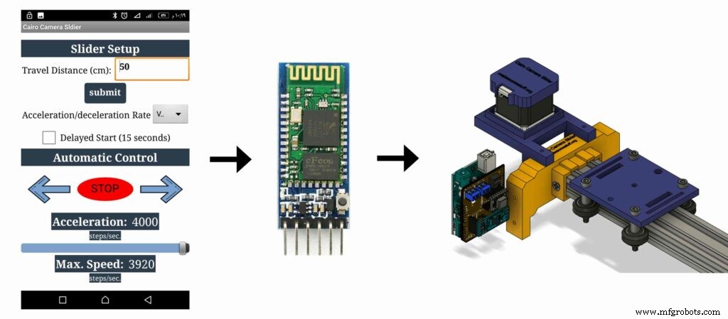
ランダムな趣味の動画を撮影するのが好きな人にとっては、電動カメラスライダーを購入するのはどういうわけか高価です。それで、私は自分で作りました。このチュートリアルでは、各ステップを実行して、Bluetoothで制御される独自の電動カメラスライダーを作成します。
今日は、カスタムメイドのAndroidモバイルアプリからBluetooth経由でワイヤレスで制御できる電動カメラスライダーを構築します。 「MITAppInventor」ツールを使用して、スライダーの移動速度、移動距離、加速/減速率など、さまざまな要素を制御できるアプリを作成しました。モバイルアプリは非常に堅牢で、アプリ内で使用しているカメラスライダーの長さを設定できます。つまり、アプリを気にすることなく、最大10メートルの長さの実際のカメラスライダーを自由に作成できます。
<図>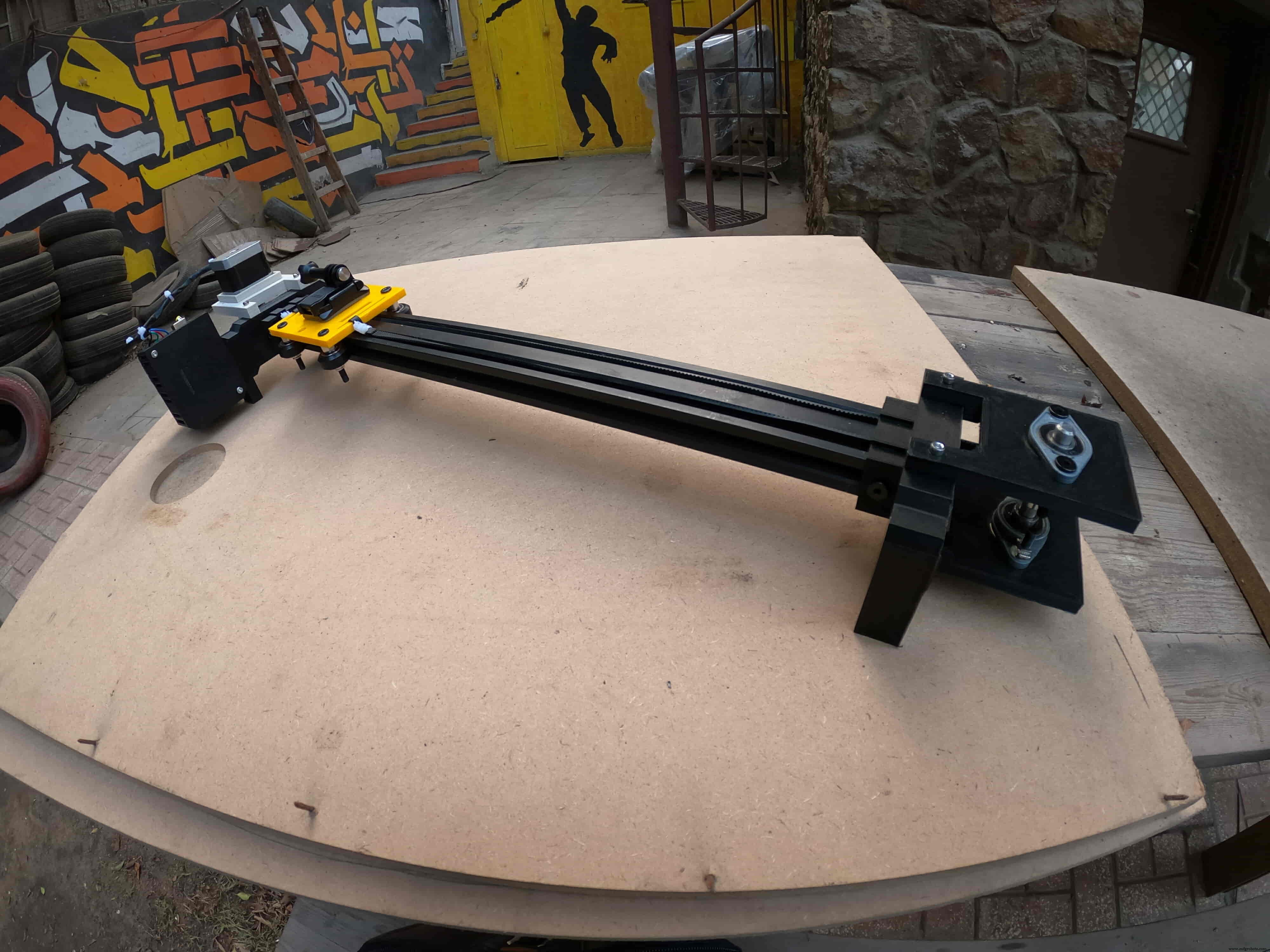
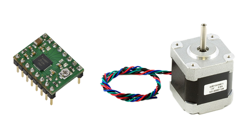
NEMA17ステッピングモーターをアクチュエーターとして使用したので、カメラスライダーを動かすのに必要なステップ数を制御できます。 Arduinoボードを使用してステッピングモーターを制御するには、Arduinoボードからコマンドを受け取り、ステッピングモーターが理解できる言語に翻訳するトランスレーターが必要です。これがA4988Pololuステッピングモータードライバーの役割です。これにより、5つの異なるマイクロステップ解像度(1/16ステップまで)が得られ、最大の移動精度と動きの滑らかさを実現します。
<図>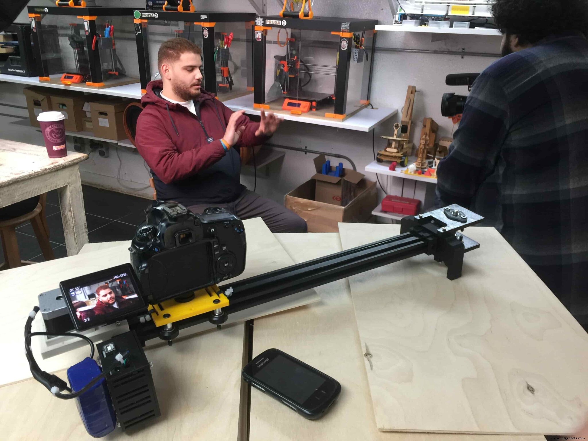
このプロジェクトは、ファブラボ/メーカースペース/ハッカースペースでの製造可能性を念頭に置いて設計されています。
CADと3Dモデリング
Fusion360を使用してカメラスライダーを設計しました。非常によく知られた、見つけやすい機械部品を使用することを選択しました。これらの機械部品は、住んでいる場所に関係なく、ほぼすべてのオンラインストアまたはオフラインストアから簡単に購入できます。
<図>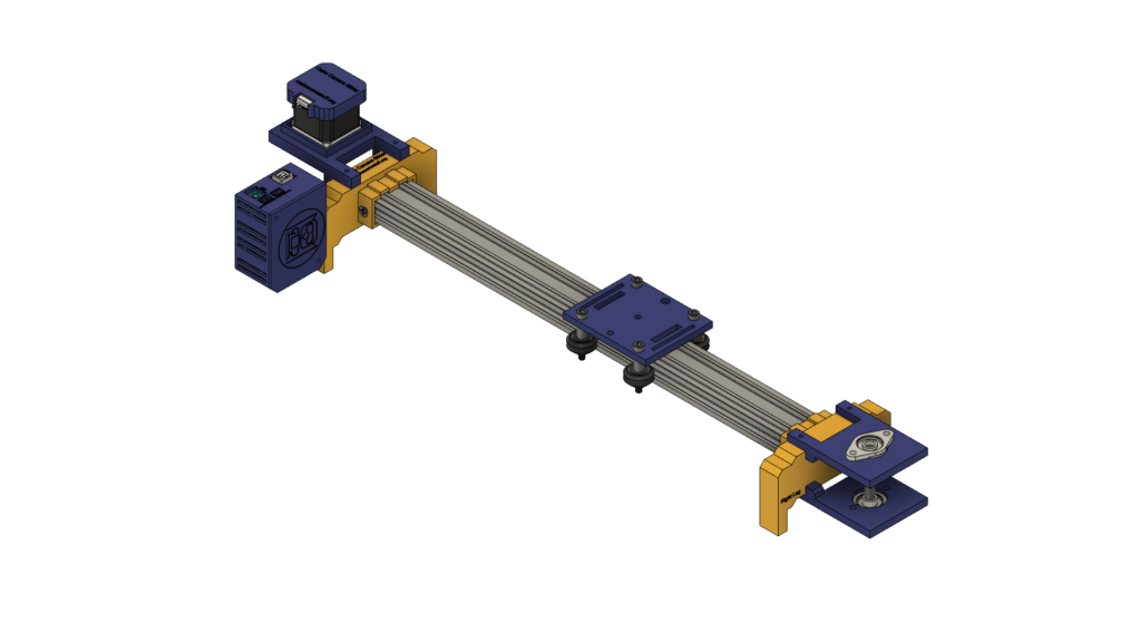
Openbuildsハードウェアを使用して機械的構造を構築し、Vスロット2040リニアレールをカメラの移動ガイドとして使用しています。 2つのプーリー、1つはステッピングモーターシャフトにあります。もう1つは、スライダーの反対側にある8mmの線形レールシャフト上にあり、タイミングベルトが開いており、ステッピングモーターの回転運動から線形運動に変換されます。
<図>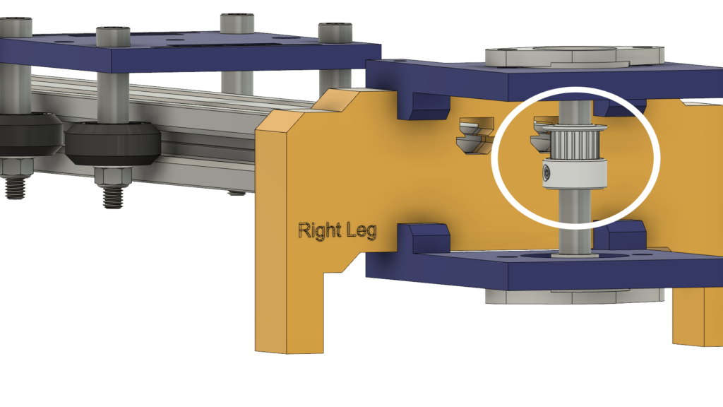 <図>
<図> 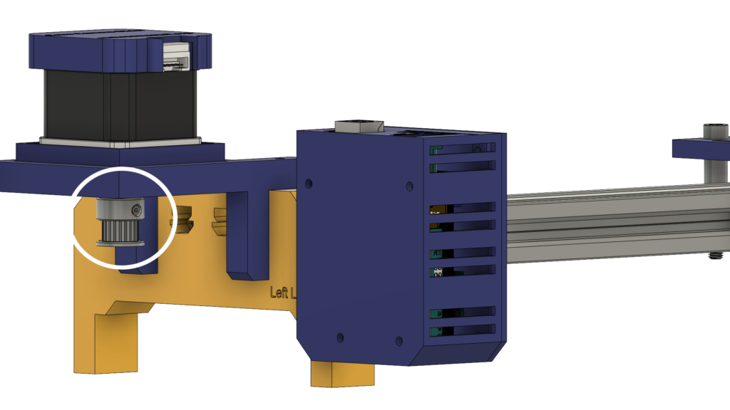
8mmリニアレールシャフトは、4本のM5ネジで上部プレートと下部プレートに取り付けられている2つの自動調心ピローフランジブロックベアリングの間に取り付けられています。
<図>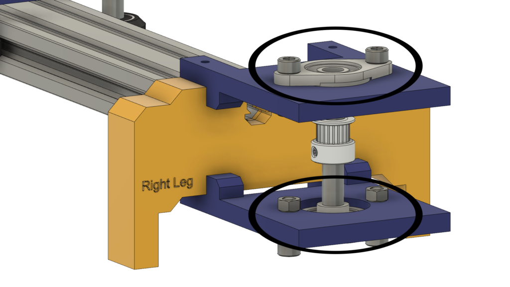
カメラの動きを非常にスムーズにするために、VスロットレールのV溝に乗る4つのデルリンVスロットソリッドホイールを使用しています。カメラプレートの中央には、標準の三脚ネジ用の直径1/4インチの穴があり、カメラを簡単に取り付けることができます。
<図>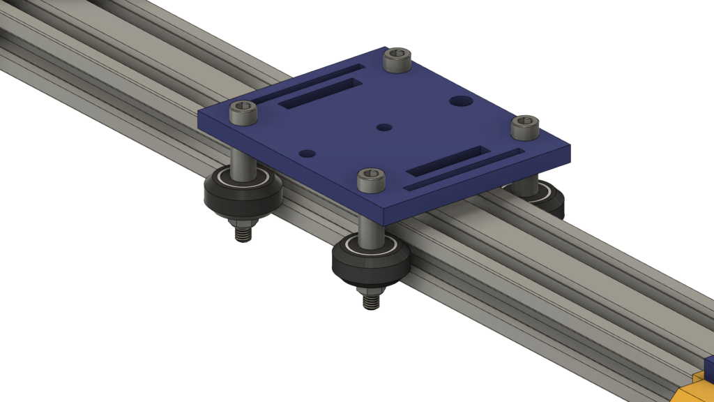
最後に、電子機器用のエンクロージャーです。すべてのカメラスライダーパーツは、m3 * 16mmのネジとナットで固定されています。
<図>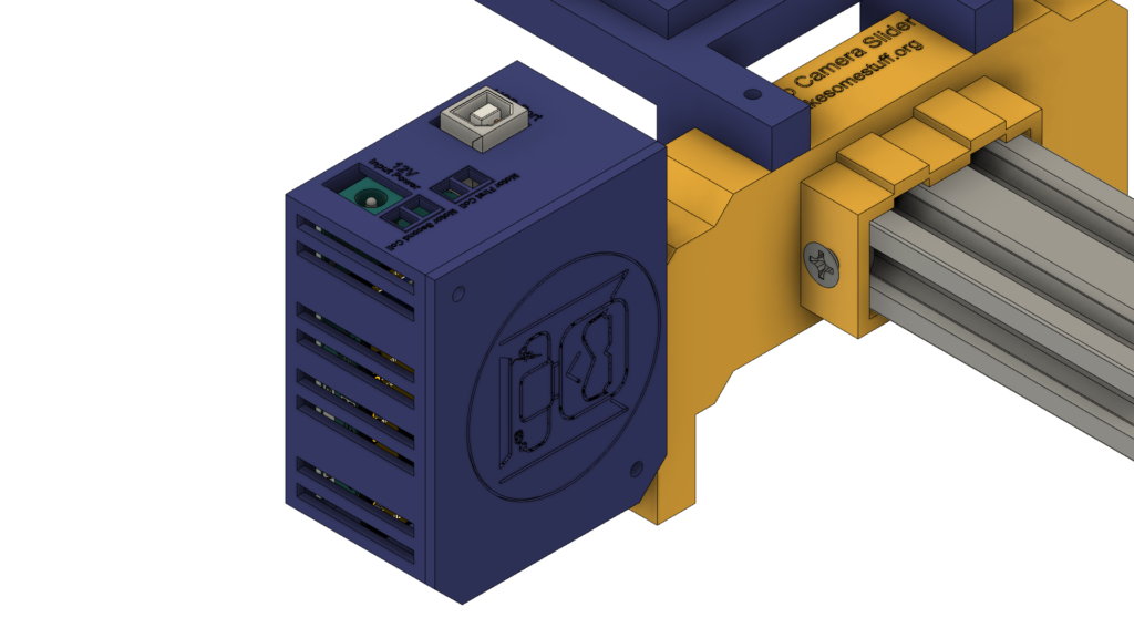
デジタルファブリケーション(3Dプリント)
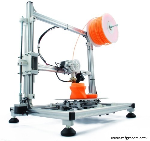
カメラスライダー本体はすべて3Dプリントされ、0.2層の高さ、20%の塗りつぶしで印刷されますが、カメラスライダーの左右の脚は、0.2層の高さ、50%の塗りつぶしで印刷されます。
STLファイルはからダウンロードできます シンギバース。
Vホイールキットアセンブリ
組み立て工程はとても簡単です、さあ!最初のステップでは、4つのソリッドVホイールを組み立てる必要があります。頑丈なVホイールキットには、ラバーホイール、2つのベアリング、2つのパーシジョンシム、およびロックナットが付属しています。
<図>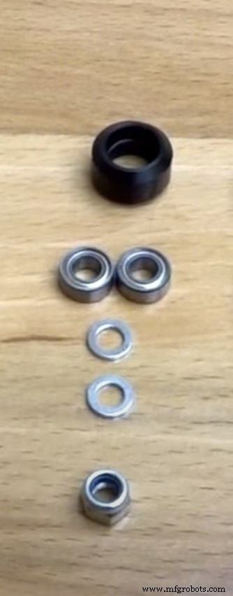
ゴムホイールの片側からベアリングを挿入し、ホイールを裏返し、ゴムホイールの内側に精密シムを1つ挿入し、最後に2番目の面側から2番目のベアリングを挿入します。
<図>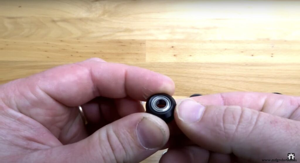 <図>
<図> 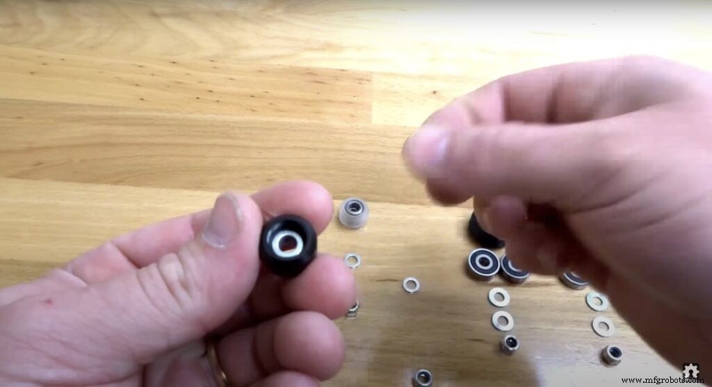 <図>
<図> 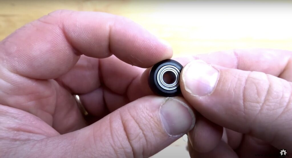
カメラスライダーメカニカルアセンブリ
まず、カメラプレートと4つのソリッドVホイールを組み立てる必要があります。 9mmアルミニウムスペーサー、精密シム、ロックナットを使用。
<図>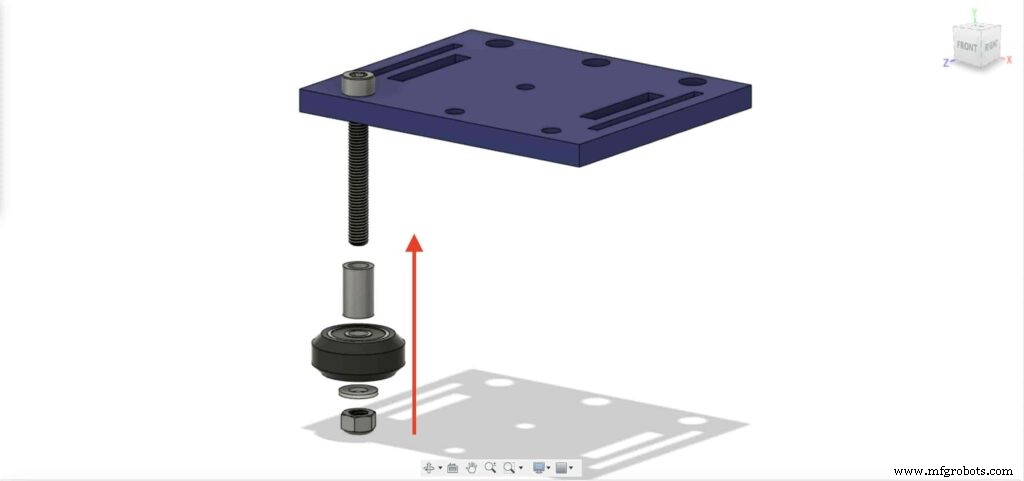 <図>
<図> 
他の3つのホイールで前の手順を繰り返します。右の2つのホイールでは、9mmスペーサーを使用します。そして、他の2つの左ホイールは、9mmスペーサーの代わりに3mmスペーサーを備えた偏心スペーサーを使用します。
<図>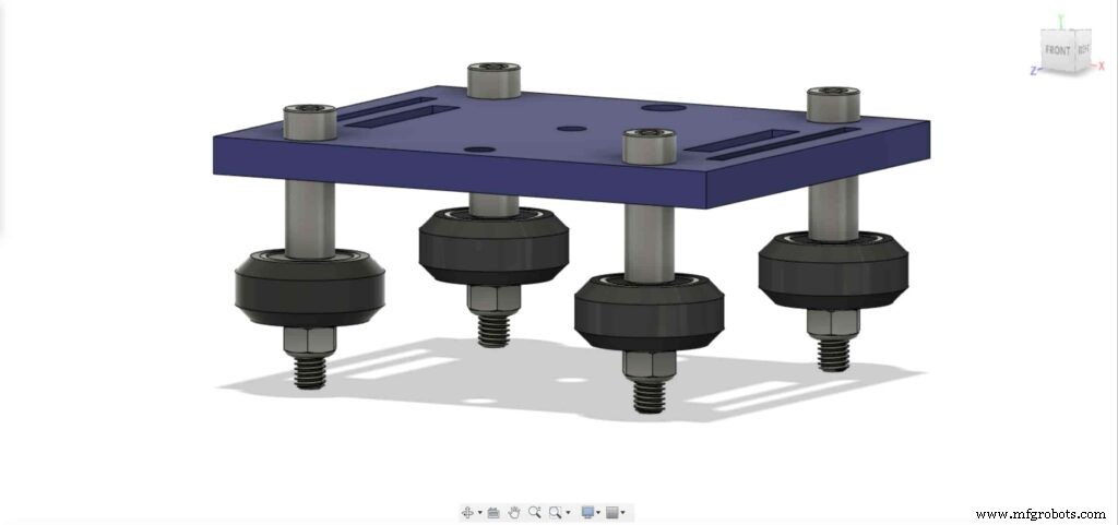
次に、カメラホルダープレートをVスロットプロファイルに挿入します。プレートが緩んで揺れていることがわかった場合は、プレートが固くなるまでエキセントリックナットを締めることができます。
<図>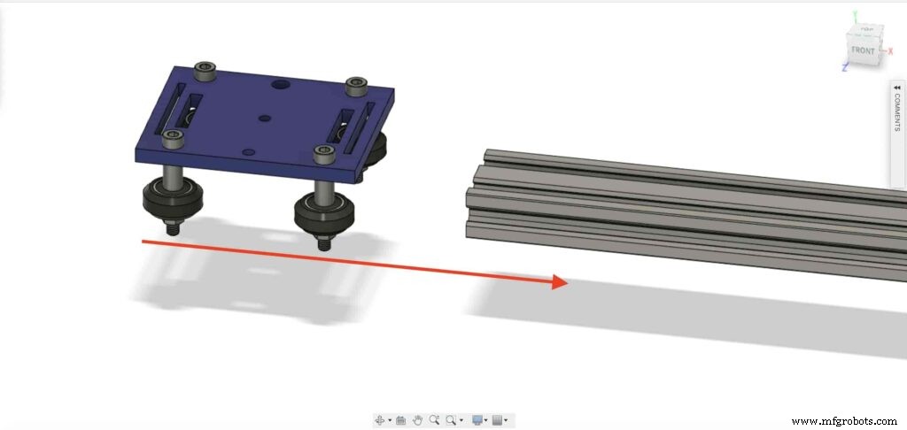 <図>
<図> 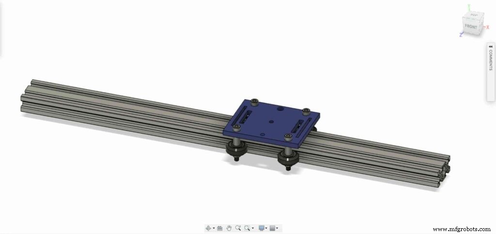
Vスロットプロファイルの両端に2つのドロップインTナットを挿入しましょう。 Vスロットプロファイルをカメラスライダーの左右の脚に接続する必要があります。
<図>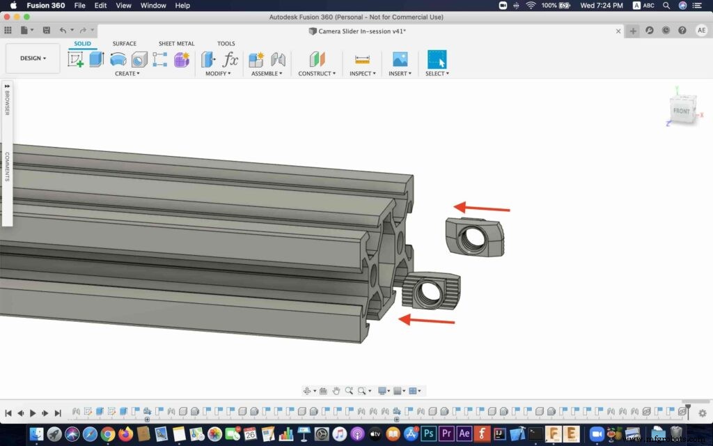 <図>
<図> 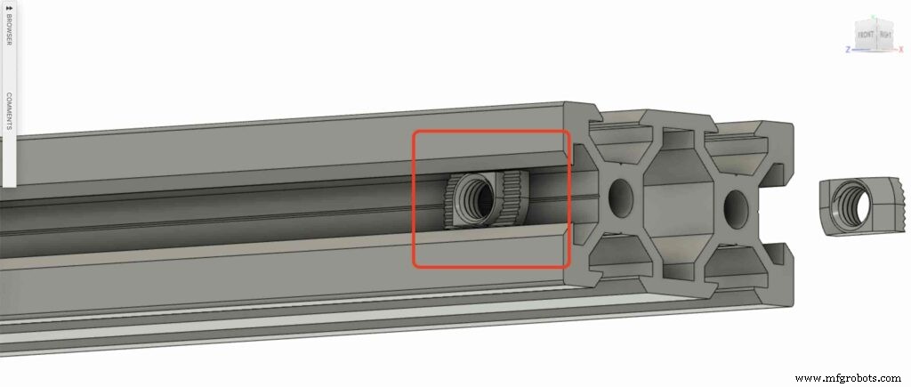 <図>
<図> 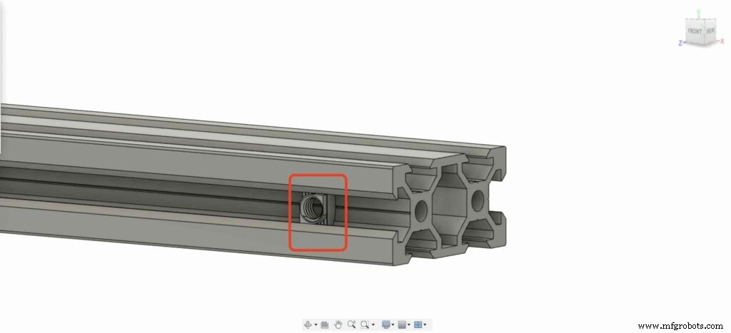
2つのカメラスライダーレッグを入手して、Vスロットプロファイルに押し込みます。
<図>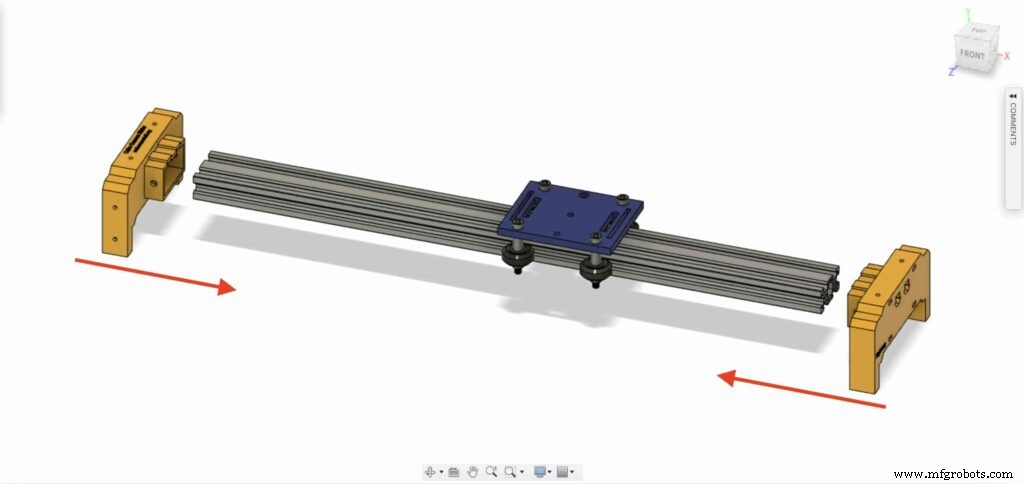 <図>
<図>  <図>
<図> 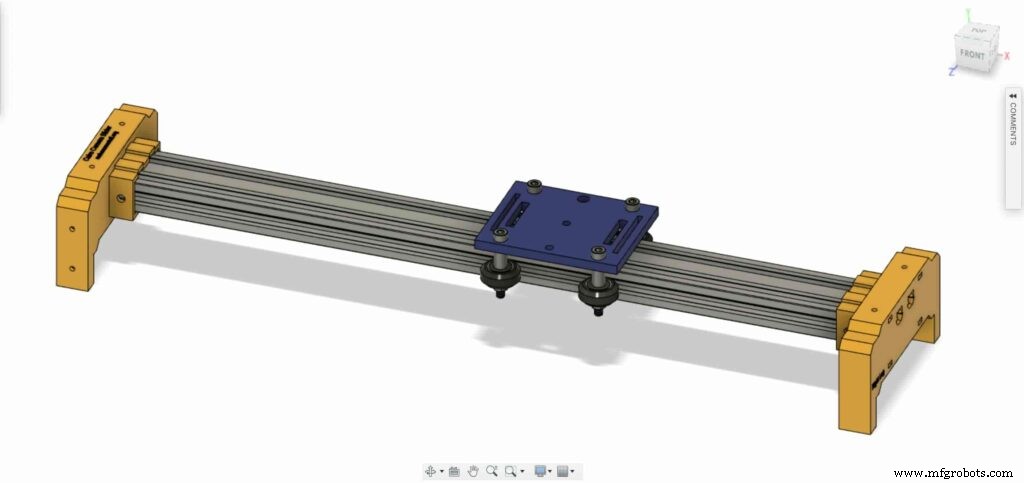
4本のM5X10mmネジを持参し、2本の脚をVスロットプロファイルで固定します。
<図>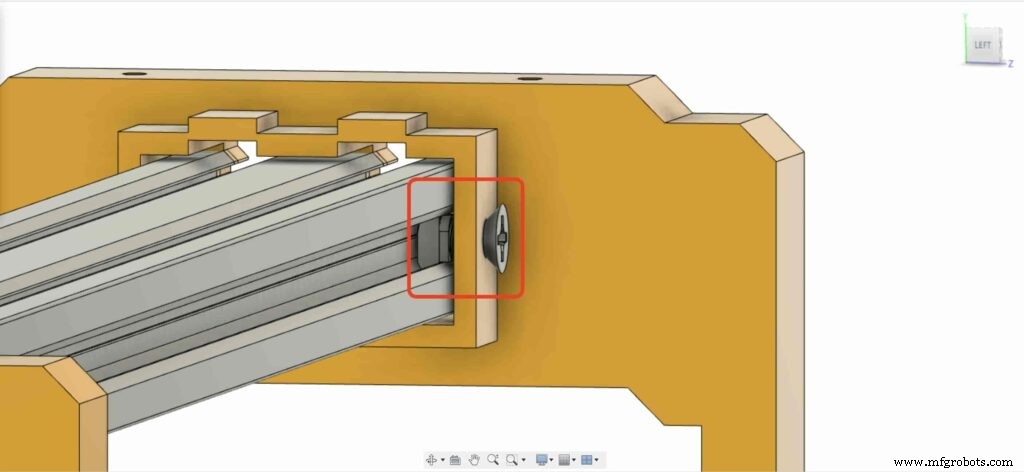 <図>
<図> 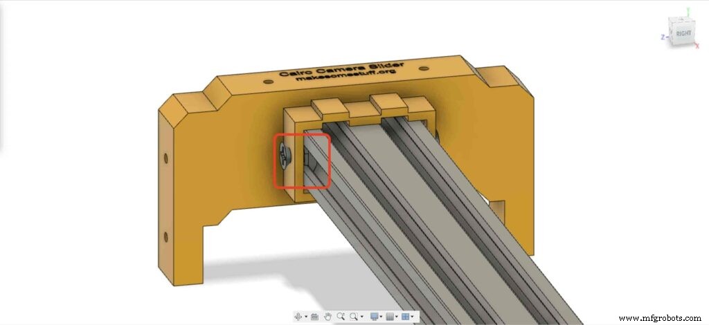
NEMA17ステッピングモーターをプレートに取り付ける必要があります。次に、4本のM3X16mmネジを使用して、モーターを所定の位置に固定します。
<図>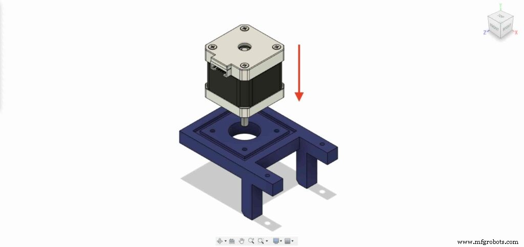 <図>
<図> 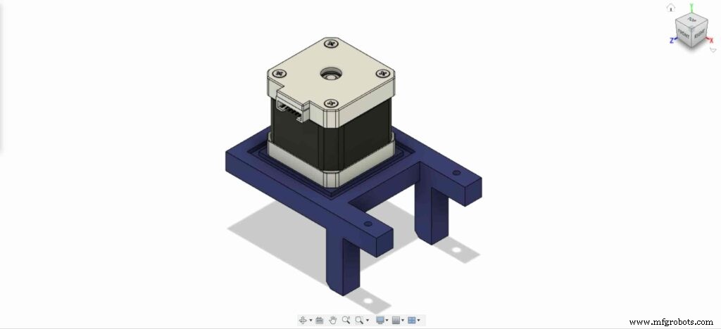 <図>
<図> 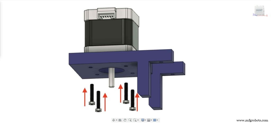 <図>
<図> 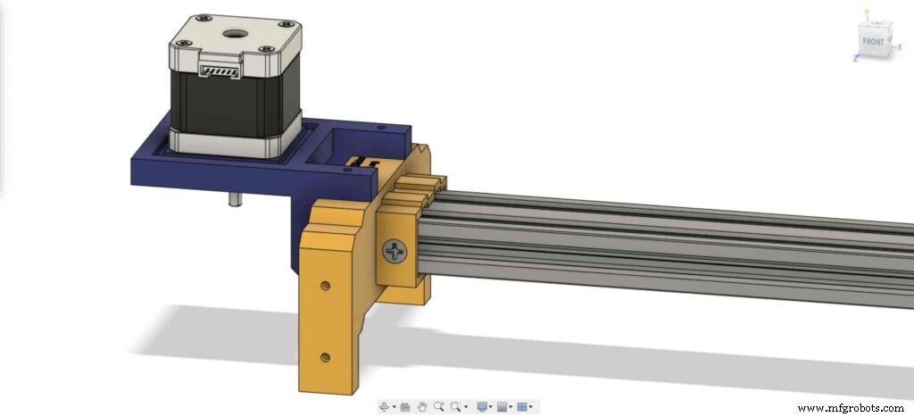
左脚で、左脚の上部ナットの場所の内側に2つのナットを挿入します。
<図>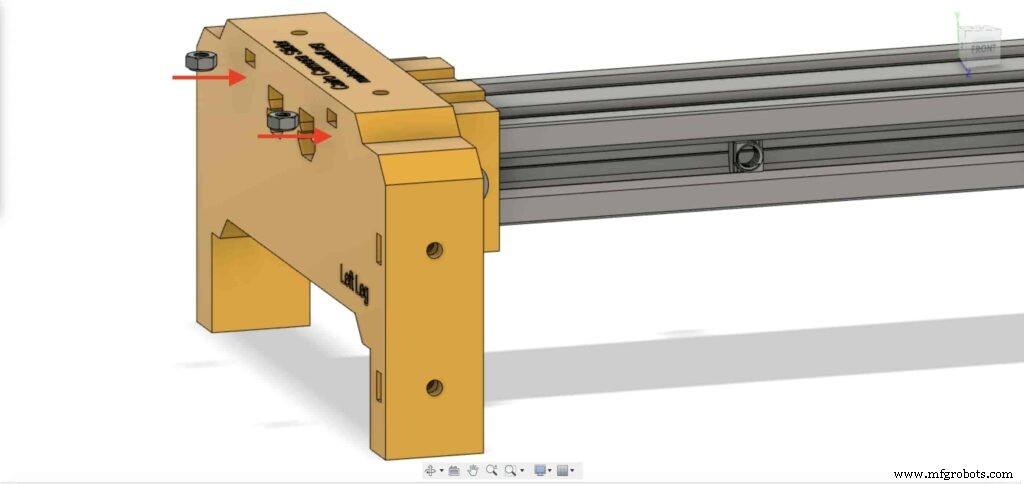 <図>
<図> 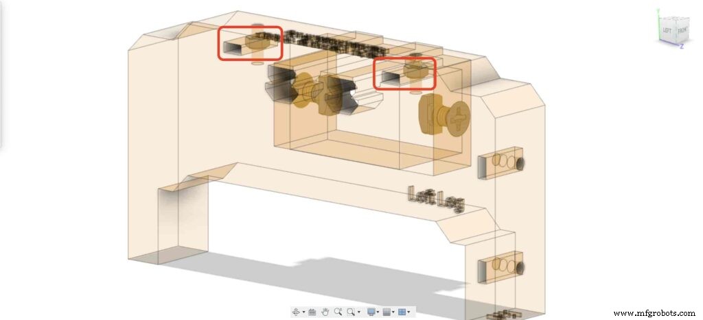
NEMA 17モータープレートを持ってきて、左脚の上部に固定します。そして、2本のM3X16mmネジを使用して、プレートを左脚に固定します。
<図>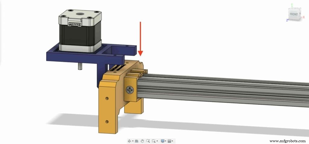 <図> <図>
 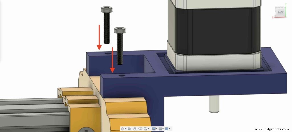 <図>
<図> 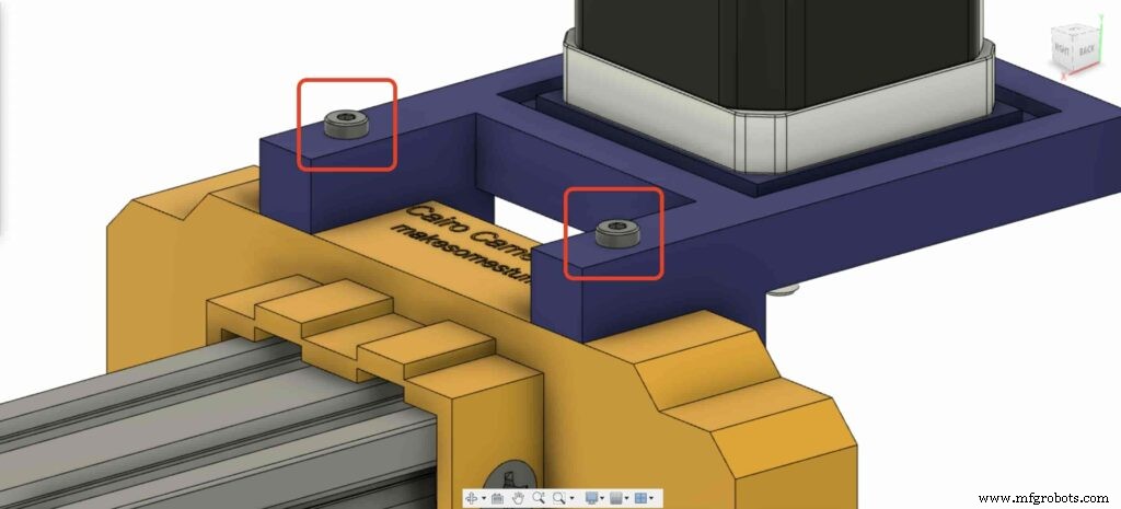
ステッピングモーターの回転運動を直線運動に変換できるようにするには、モーターシャフトにGT2ボア5mmプーリーを取り付ける必要があります。六角レンチを使用して、プーリーセットネジを締めて所定の位置に固定します。
<図>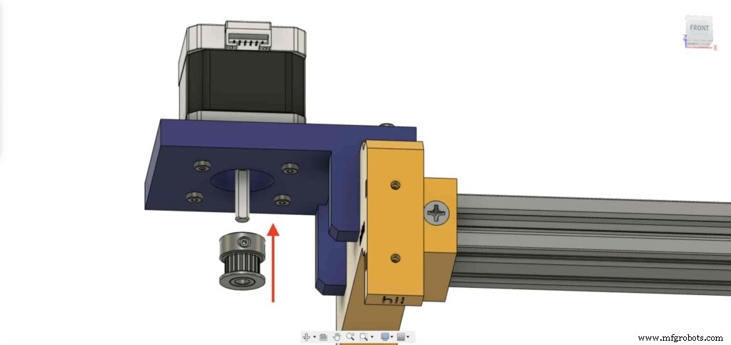 <図>
<図> 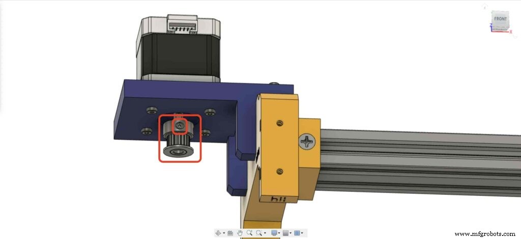
カメラスライダーの右脚に移動し、4つのM3ナットを脚ナットの場所に挿入します。
<図>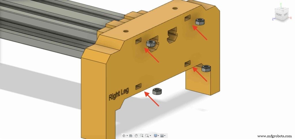 <図>
<図> 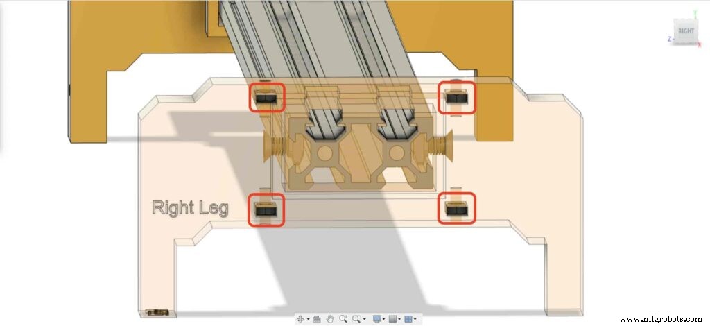
次に、右脚ベアリングをカメラスライダーの右脚の上部に2枚のプレートを置きます。
<図>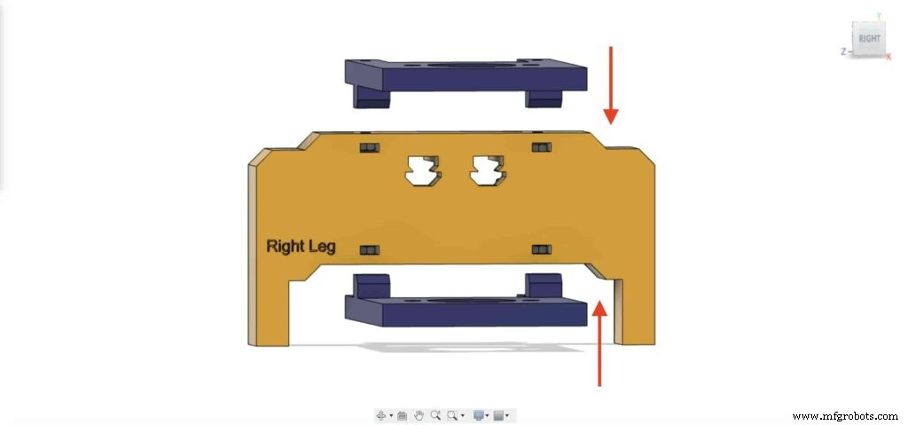 <図>
<図> 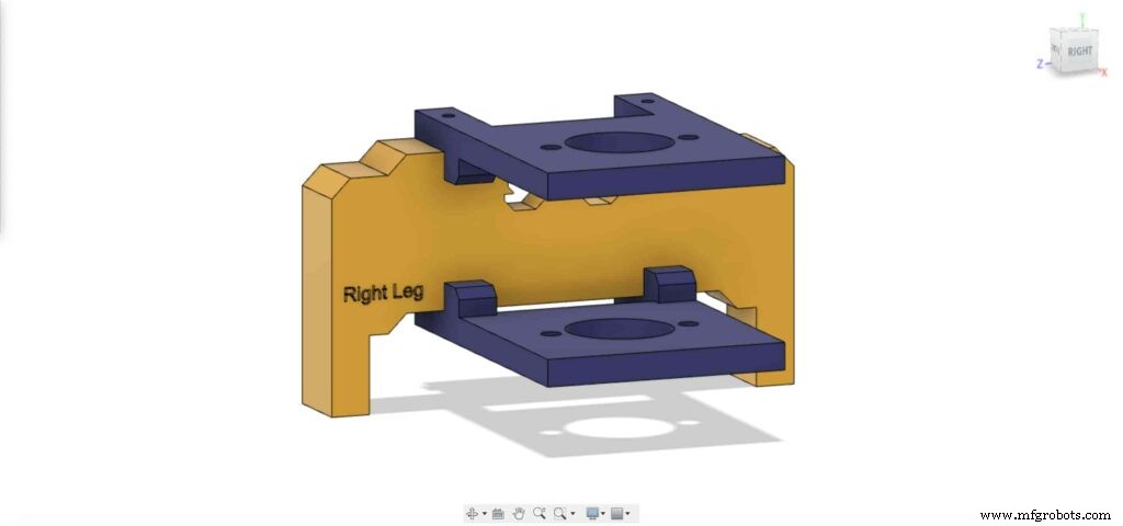
4本のM3X16mmネジを使用して、カメラスライダーの右脚に2つのプレートを固定し、所定の位置に固定します。
<図>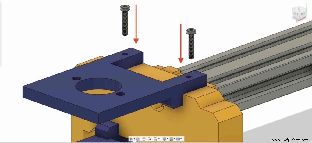 <図>
<図> 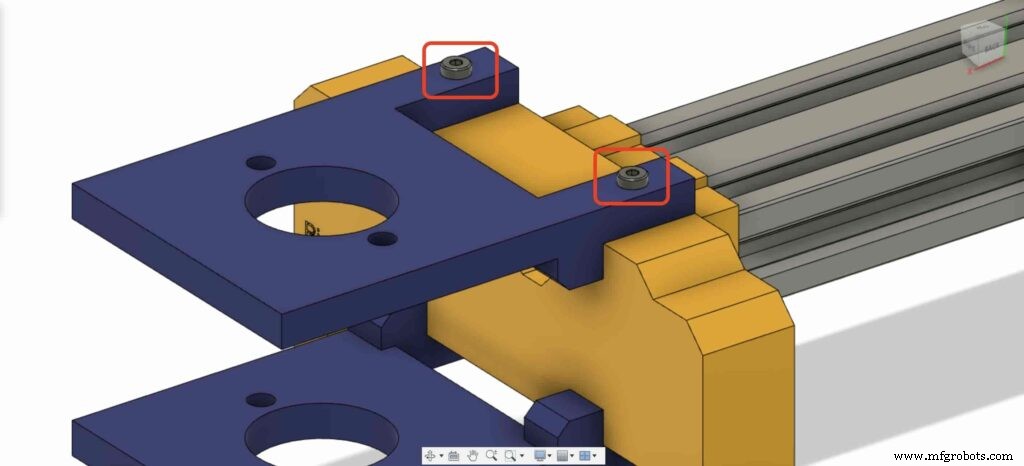 <図>
<図> 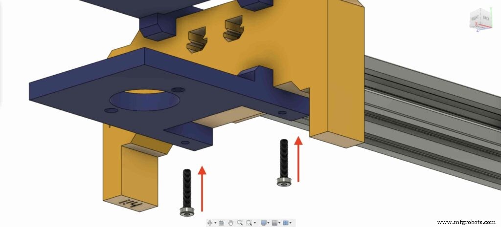 <図>
<図> 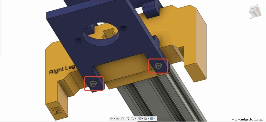
8mmフランジブロックベアリングの1つを持ってきて、右上のレッグプレートに取り付けます。 2本のM5X20mmネジと2本のM5ナットを使用します。
<図>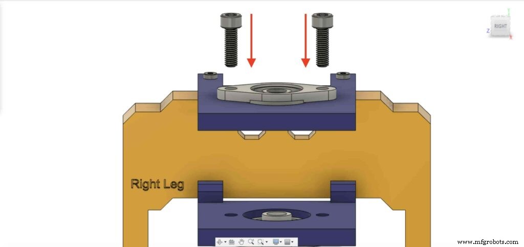 <図>
<図> 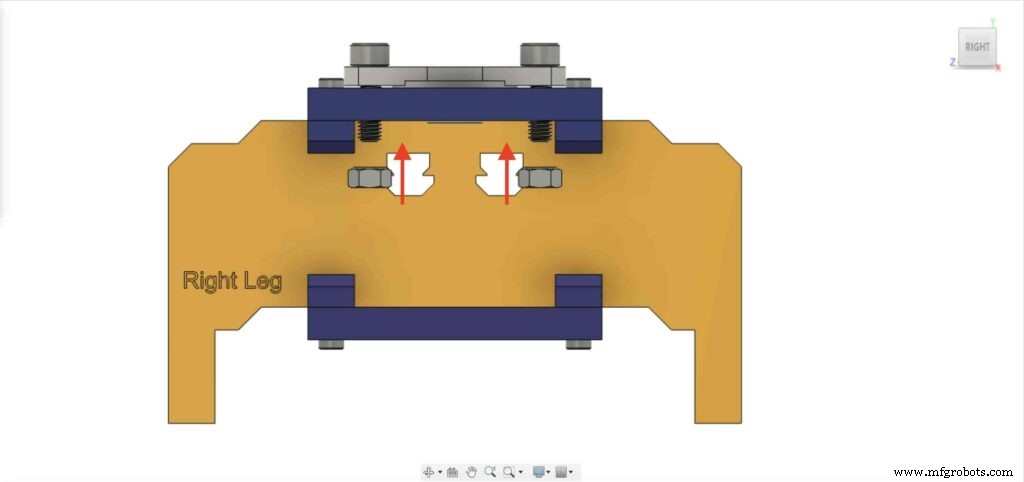 <図>
<図> 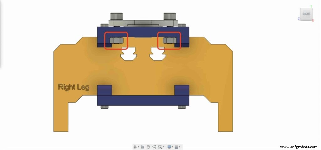
2番目の8mmフランジベアリングブロックで前の手順を繰り返して、カメラスライダーの右脚の底板に固定する必要があります。
<図>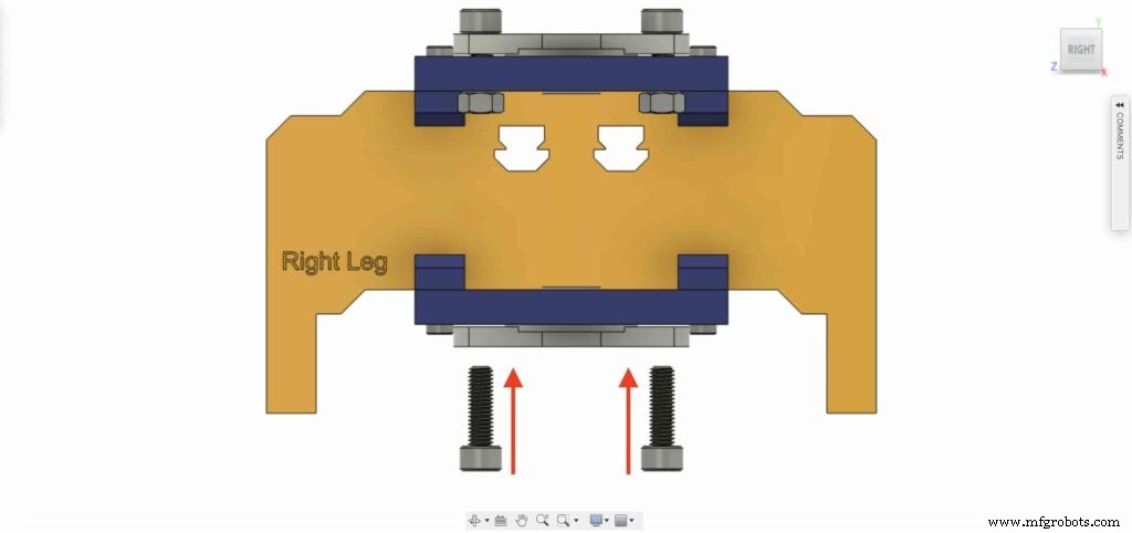 <図>
<図> 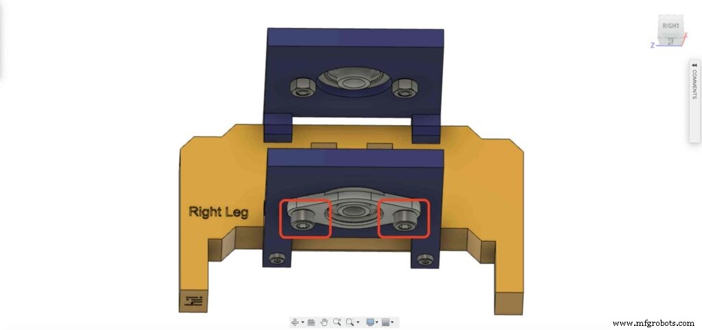 <図>
<図> 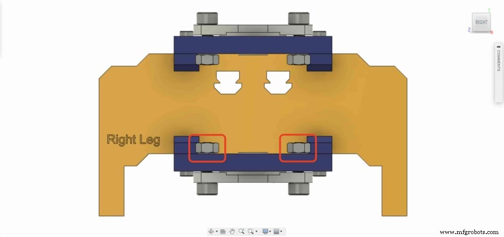
8mmリニアレールシャフトを8mmフランジベアリングブロックの下側から挿入し、上に押し込みます。次に、8mmボアプーリーをリニアレールシャフトに挿入し、プーリーの止めネジを締めて固定します。
<図>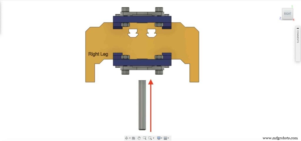 <図>
<図> 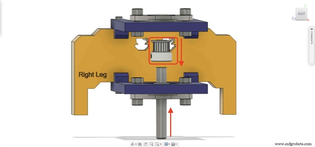 <図>
<図> 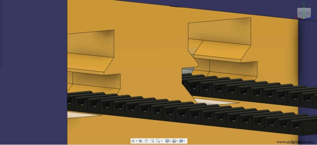
チェックポイント、1つを除いてすべてのカメラスライダーメカニズムを組み立てました。タイミングベルト。やってみましょう。
<図>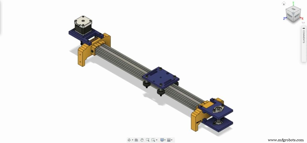
NEMA17モーターの5mmボアプーリーの6mmタイミングベルトを回転させます。また、右脚には8mmボアプーリー。最後に、カメラプレートでベルトを締めます。
<図> <図> 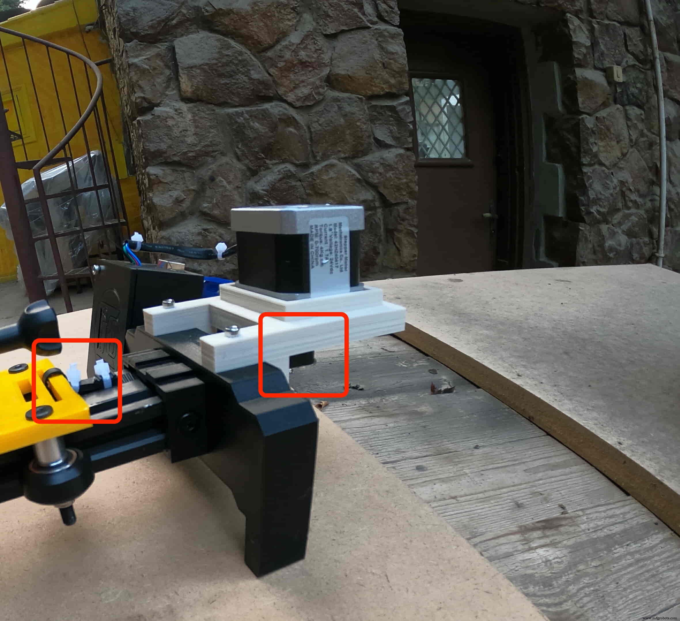
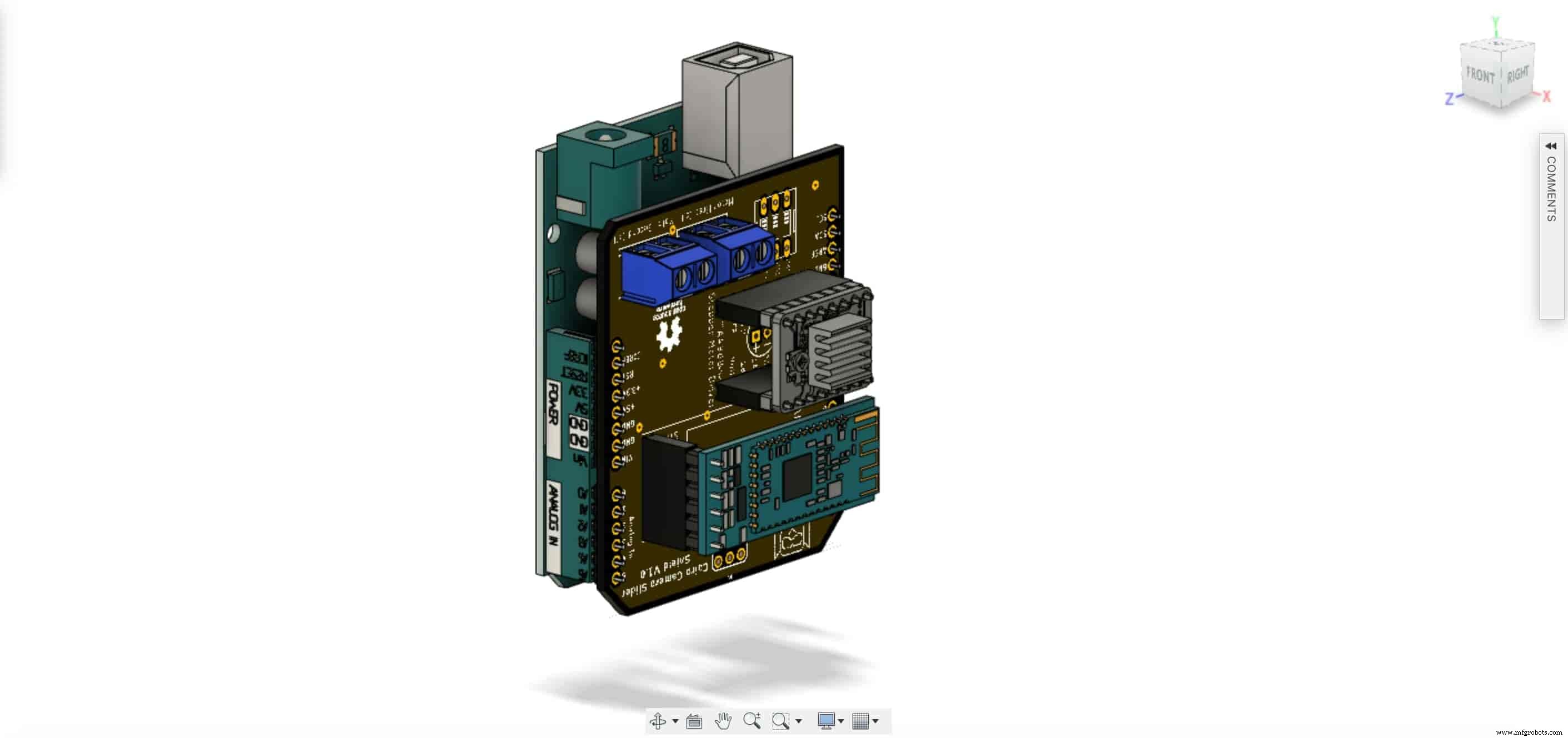
コントロールボードを組み立てる時が来ました。 Arduinoボードの上部にCairoカメラスライダーArduinoシールドを挿入します。
<図>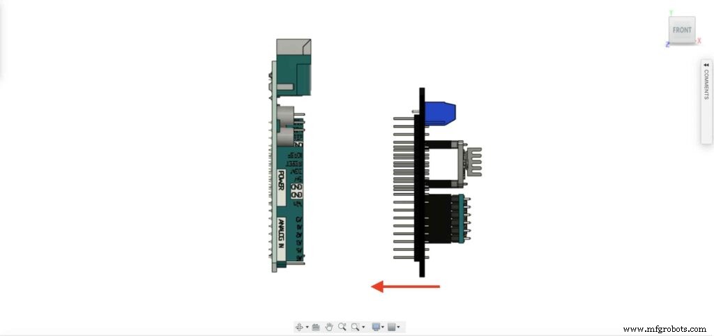 <図>
<図> 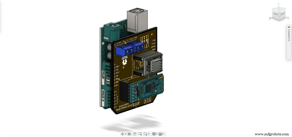
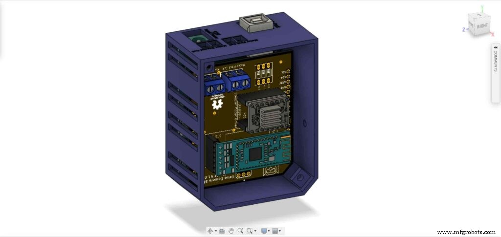
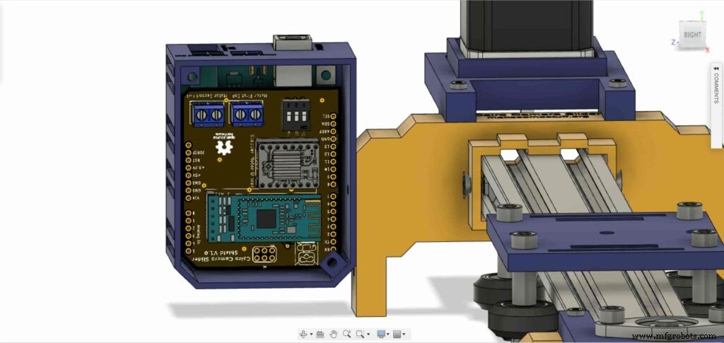
ArduinoボードとCairoカメラスライダーシールドをコントロールボードエンクロージャー内に挿入します。
<図>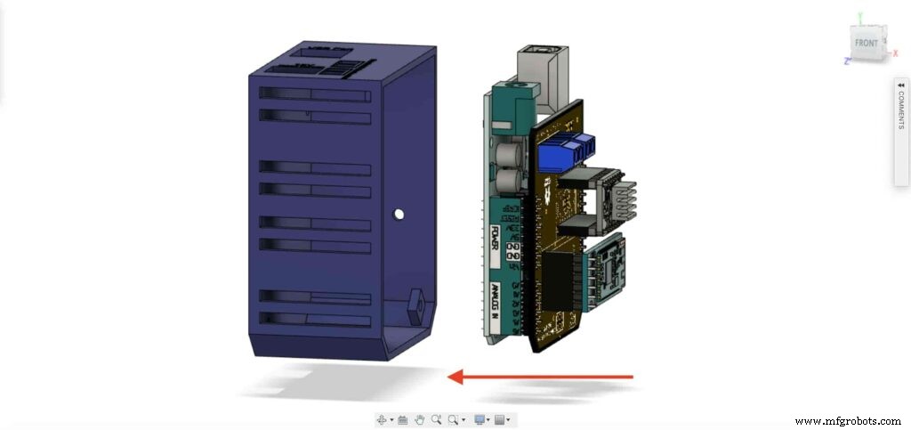
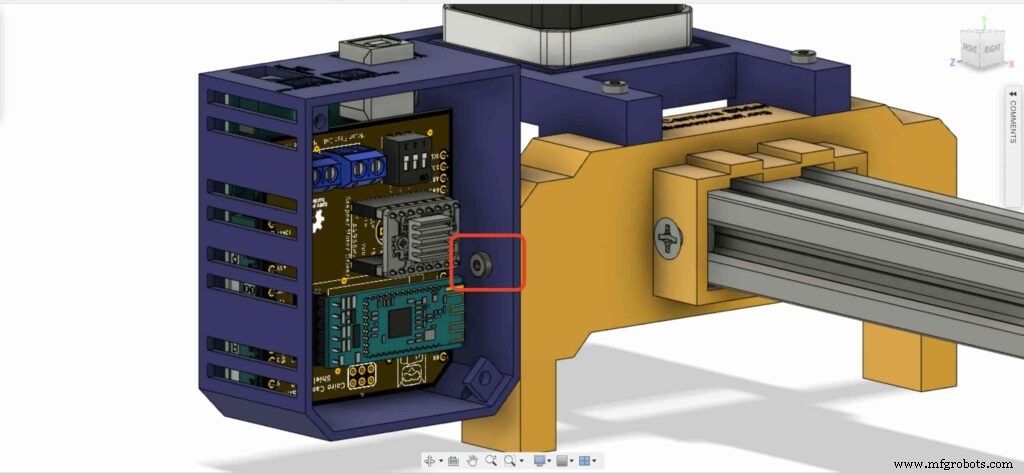
insert two M3 nuts inside the left leg nuts place.
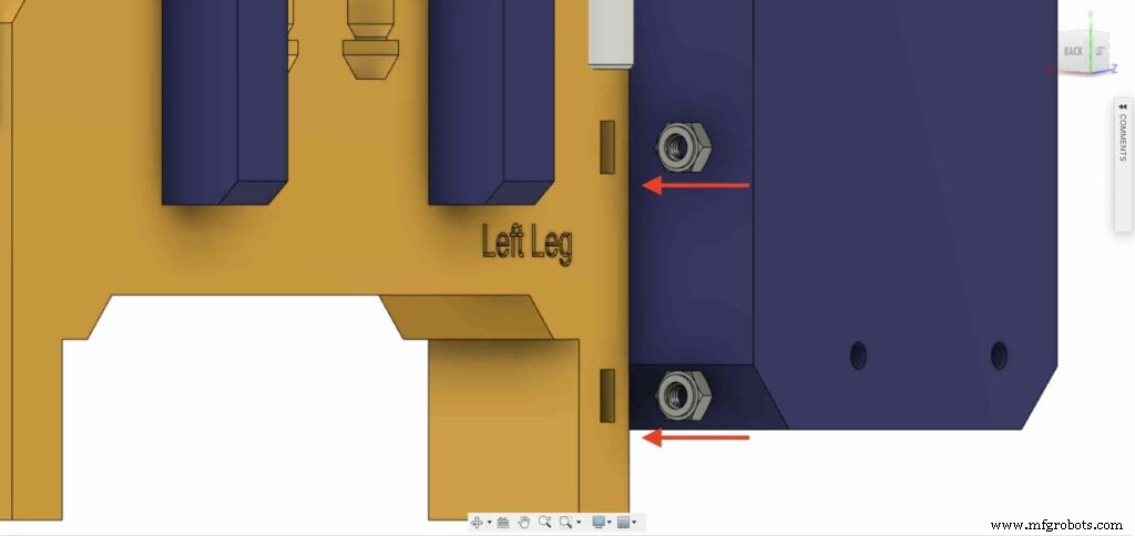
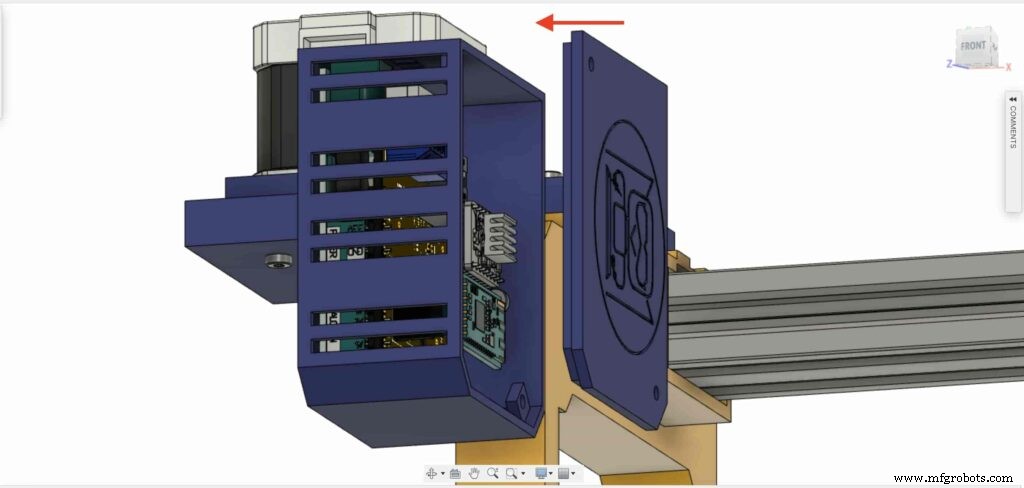
install the control board enclosure to the Cairo Camera Slider left leg with M3X16mm screws.

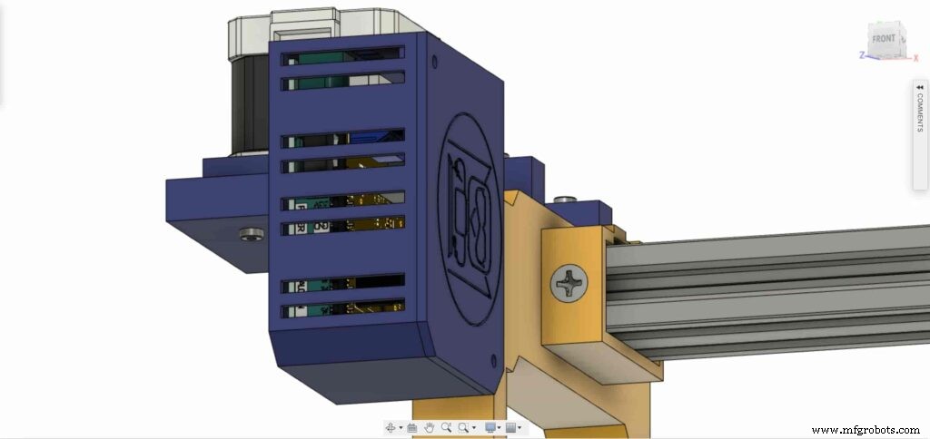
close the enclosure box top face with two M3 screws and nuts, and that’s it!

Stepper Motor Test Control
After assembling all the parts together, We need to test it to make sure that everything is installed in its place correctly. Now, we need to connect the stepper motor with the Arduino board through the A4988 stepper motor driver and write some code to run that thing.
A4988 stepper motor driver
To control any stepper motor using the Arduino board or any microcontroller, you will need a stepper motor driver which works as a translator, takes commands from the Arduino board and translate it to the language that the motor understands.
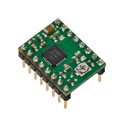
there are a lot of stepper motor drivers out there but we will use the A4988 driver 。 This driver allows us to control one bipolar motor at up to 2A output current per coil, it’s very simple to interface with the Arduino board you only need two digital pins to fully control your motor step and direction, allows you to control the maximum current output easily with an onboard potentiometer, and gives you a micro-step resolution down to 1/16 micro-step.
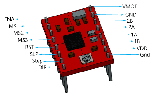
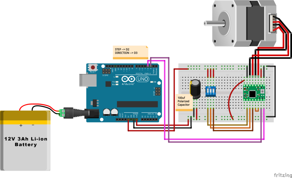
VMOT, GND: It’s the power connection pins for the stepper motor itself, it can be 8V-35V. In our case, we are connecting a 12V 3A power source on those pins with a 100uf decoupling capacitor to protect the A4998 board from any power spikes.
2B, 2A: the output pins for the stepper motor first coil which can deliver up to 2A.
1A, 1B: the output pins for the stepper motor second coil which can deliver up to 2A as well.
VDD, GND: Used for driving the internal logic circuitry, it can be 3V to 5.5V. It’s totally isolated from the VMOT pin.
EN: Stands for “Enable” it’s an active LOW(0V) input pin, which means when this pin pulled LOW(0V) the A4988 chip is enabled. And when pulled HIGH(5V) the A4988 chip is disabled. By default, this pin is pulled LOW(0V). So, the chip is always enabled unless you pull it HIGH(5V).
MS1, MS2, MS3: Through these pins, you can select your motor microstepping resolution(step size). The A4988 gives you five different microstep resolutions (full step, half step, quarter step, Eighth step, Sixteenth step) 。 By applying appropriate logic levels to these three pins we can set the motors to one of the five step resolutions.
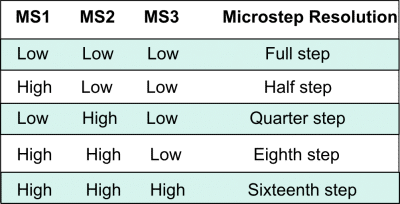
By default, the MS1, MS2, MS3 pins have internal pull-down resistors. So leaving these three microstep selection pins disconnected results in full-step mode.
RST, SLP: The “Reset” pin is an active LOW(0V) input pin, which means when it pulled LOW(0V), all the step inputs are ignored it also resets the translator itself until you pull it HIGH(5V). The “Sleep” pin also an active LOW pin, pulling it LOW, puts the driver in the sleep mode minimizing the power consumption. By default, the “Sleep” pin is pulled HIGH(5V).
STP, DIR: The “Step” pin is responsible for controlling the number of steps that the motor is rotating, each pulse to the “Step” pin corresponds for one microstep in the direction selected by the “Direction” pin, the faster the pulses, the faster the motor will rotate. By applying logic value HIGH(5V) on the “Direction” pin it makes the motor rotate clockwise, by applying LOW(0V) it makes the motor rotate counterclockwise(it may differs from one to another according to your motor wiring with the driver).
NEMA17 Stepper Motor
Stepper motors are DC motors that can rotate in precise increments, they are used in many applications like 3D printers to align the printhead and CNC machines to control the movement of the cutting tool and this is because they are very accurate and precise.
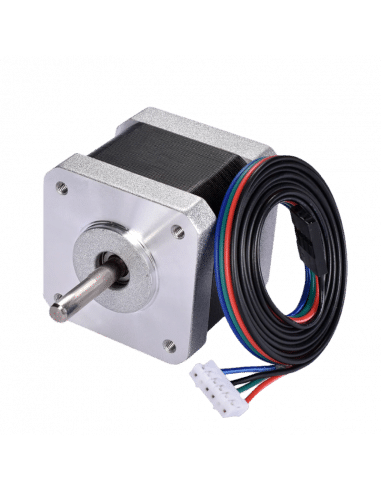
Unlike DC motors, stepper motors are controlled by applying DC electrical pulses to their internal coils. Each pulse makes the shaft advance by one step or a fraction of step which is called “Microstepping”. So, you can control precisely how many steps or even fraction steps you want the motor shaft to move. Another great advantage of using stepper motors is that it can move very precisely and accurately at very slow speeds without even stalling.
The type of motor we are using in this project is the NEMA 17 Bipolar stepper motor 。 The bipolar stepper motor has two internal coils and it usually has four wires, two wires per coil. unlike the Bipolar stepper motor which has five wires. The “Step Angle” of the motor is 1.8° which indicates how much the shaft advances in each full step, the motor works on 9V but if you want to get the maximum power of it use a 12V power source.
So, by connecting the stepper motor with the A4988 stepper motor driver, we can control how many steps we need the motor to move and in what direction. Also, we can set the “microstep” mode is it full step, half step, quarter step, ….. Let’s take a look at the wiring diagram.
Wiring Diagram
As we stated before, we need to make a small check to make sure that everything we assembled before is right in its place and moving properly. Now, we will wire all the hardware together, the NEMA 17 stepper motor with the A4988 stepper motor driver to the brain, the Arduino board. And using a 12V 3A Lithium-Ion battery to feed the motors with the power it needs.
Arduino Code
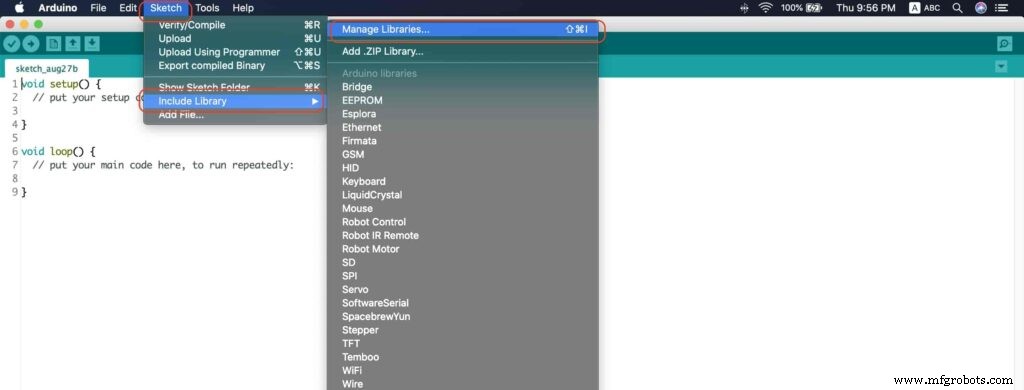
AccelStepper Library Installation
The Installation is pretty simple, we need to open Arduino IDE. From the “Sketch” menu. Select Include Library –> Manage Libraries…
A new window should appear, search for “AccelStepper” and install the library made by “Mike McCauley”. Easy right!
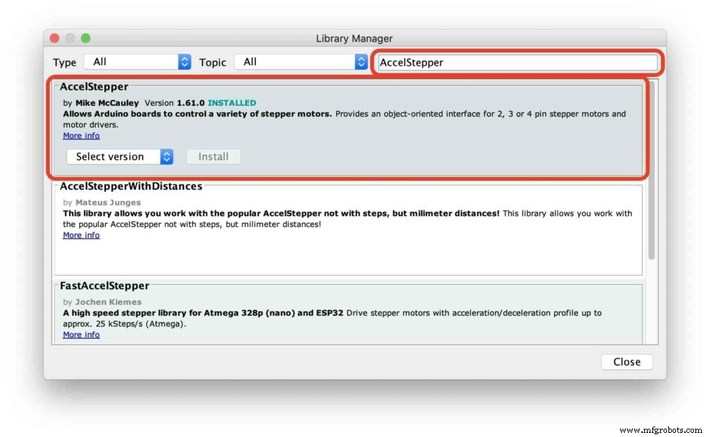
After installing the AccelStepper library, you should see it in the examples menu.
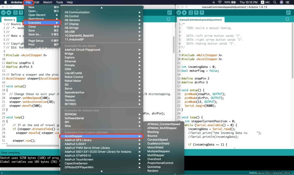
I wanna make sure that the AccelStepper library is installed correctly and my stepper motor connection with the A4988 motor driver is right and my power management is fine. So, let’s write some lines of code to run our stepper motor forward and backward.
// Bounce stepper test program
// Make a single stepper bounce from one limit to another
// Copyright (C) 2020 makesomestuff.org

#include
#define stepPin 2
#define dirPin 3 // Define a stepper and the pins it will use

AccelStepper stepper(AccelStepper::DRIVER, stepPin, dirPin); //create an object. the pin "2" is the step pin, "3" is the direction pin.

void setup()
{
 // Change these to suit your stepper if you want
 stepper.setMaxSpeed(100);
 stepper.setAcceleration(20);
 stepper.moveTo(500);
}

void loop()
{
 // If at the end of travel go to the other end
 if (stepper.distanceToGo() ==0)
 stepper.moveTo(-stepper.currentPosition());
 stepper.run();
}
The code logic is pretty straightforward, we initialized an object from the AccelStepper library, we defined two constants (stepPin, dirPin) that two digital pins is used by the A4988 stepper motor driver to control the movement of the motor itself.
#include

#define stepPin 2
#define dirPin 3 // Define a stepper and the pins it will use

AccelStepper stepper(AccelStepper::DRIVER, stepPin, dirPin); //create an object. the pin "2" is the step pin, "3" is the direction pin.
Inside the void setup function, we set the Max. speed of the stepper motor to 100 steps/sec. Also, we set the acceleration/deceleration rate to 20 steps/sec. lastly, we used the moveTo() function to tell the motor to move 500 steps.
void setup()
{
 // Change these to suit your stepper if you want
 stepper.setMaxSpeed(100);
 stepper.setAcceleration(20);
 stepper.moveTo(500);
}
Inside the void loop function, we are checking if the motor reached it’s position or not. If it reached the position, it will bounce back. and if it didn’t reach it’s position yet, it will keep running.
void loop()
{
 // If at the end of travel go to the other end
 if (stepper.distanceToGo() ==0)
 stepper.moveTo(-stepper.currentPosition());
 stepper.run();
}
Camera Slider Full Wireless Control
We have done great things so far. Let’s continue! The next step after testing everything, is to work on the mobile app that we will use to control the camera slider movement and send the orders to it. Also, we need to work on the Arduino code that will receive the data from the mobile app and according to these data it will take some actions like moving the motor, changing speed, acceleration, and so on…
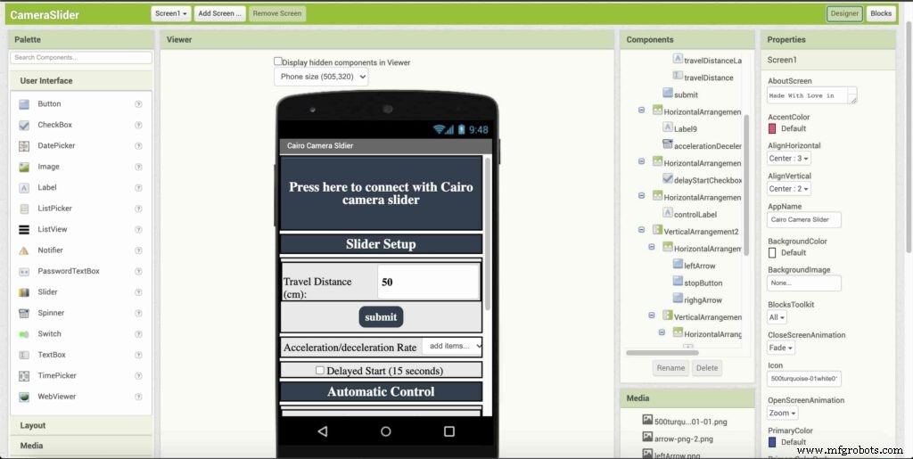
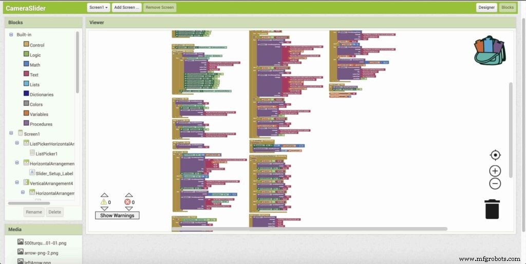
Building The Mobile App
To build the mobile app, I used the MIT App inventor tool that allows you to create mobile apps that run on any Android smartphone. The tool is pretty simple since you only drag and drop some pre-made code blocks to build the logic of your program, also you use some premade blocks to build the app user interface. You can access the source of the mobile app from the link down below. Feel free to edit and share, it’s open-source. Mobile App Source
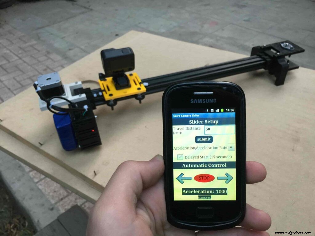
The image down below, a brief explanation for each button function and how it works.
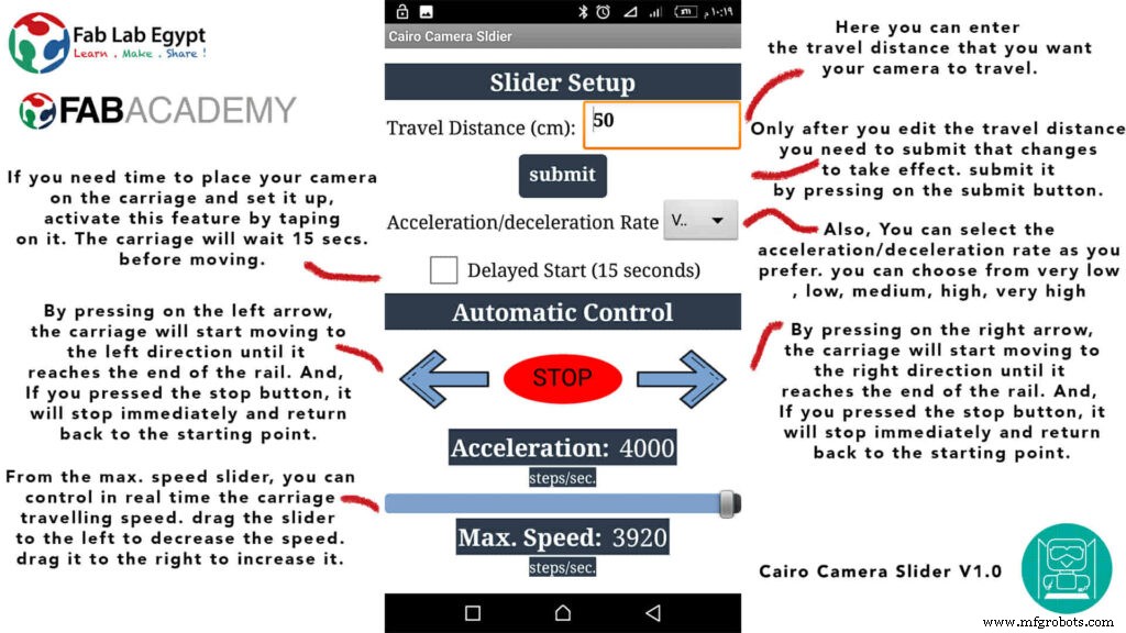
That mobile app will communicate with the Cairo camera slider wirelessly over the Bluetooth communication. So, the next step is to connect a Bluetooth module to the last circuit we built before and upload some lines of code to the Arduino board to be able to establish the communication between the mobile app and the Cairo camera slider.
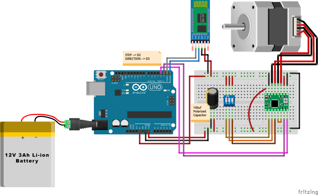
Wiring Diagram
It’s the time to connect all things together, previously we connected the stepper motor, stepper motor driver, Arduino UNO, and the battery together and tested the circuit and it worked fine. Now, and after building the mobile app, we need to connect the HC-05 Bluetooth module to our circuit.
To make it wireless we will use the HC-05 Bluetooth module which has wide use, it can set as slave or master as well (unlike the HC-06 module which can work only as a slave) which means that you can make a Bluetooth connection between two different Arduino boards. the HC-05 Bluetooth module is an SPP (Serial Port Protocol) module, which means that it communicates with the Arduino board via the Serial communication. You only need to connect the Tx and the Rx pins between the HC-05 module and the Arduino UNO board.
- Tx(Arduino) --> Rx(HC-05)
- Rx(Arduino) --> Tx(HC-05)
- 5V(Arduino) --> VCC(HC-05)
- GNND(Arduino) --> GND(HC-05)
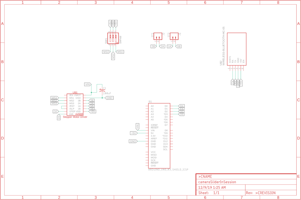
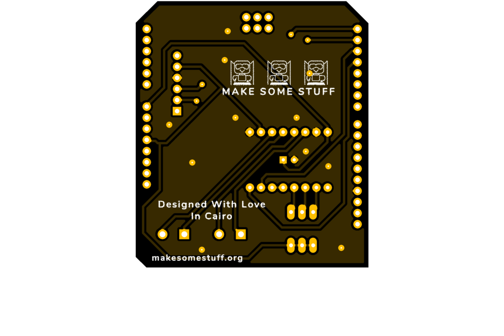
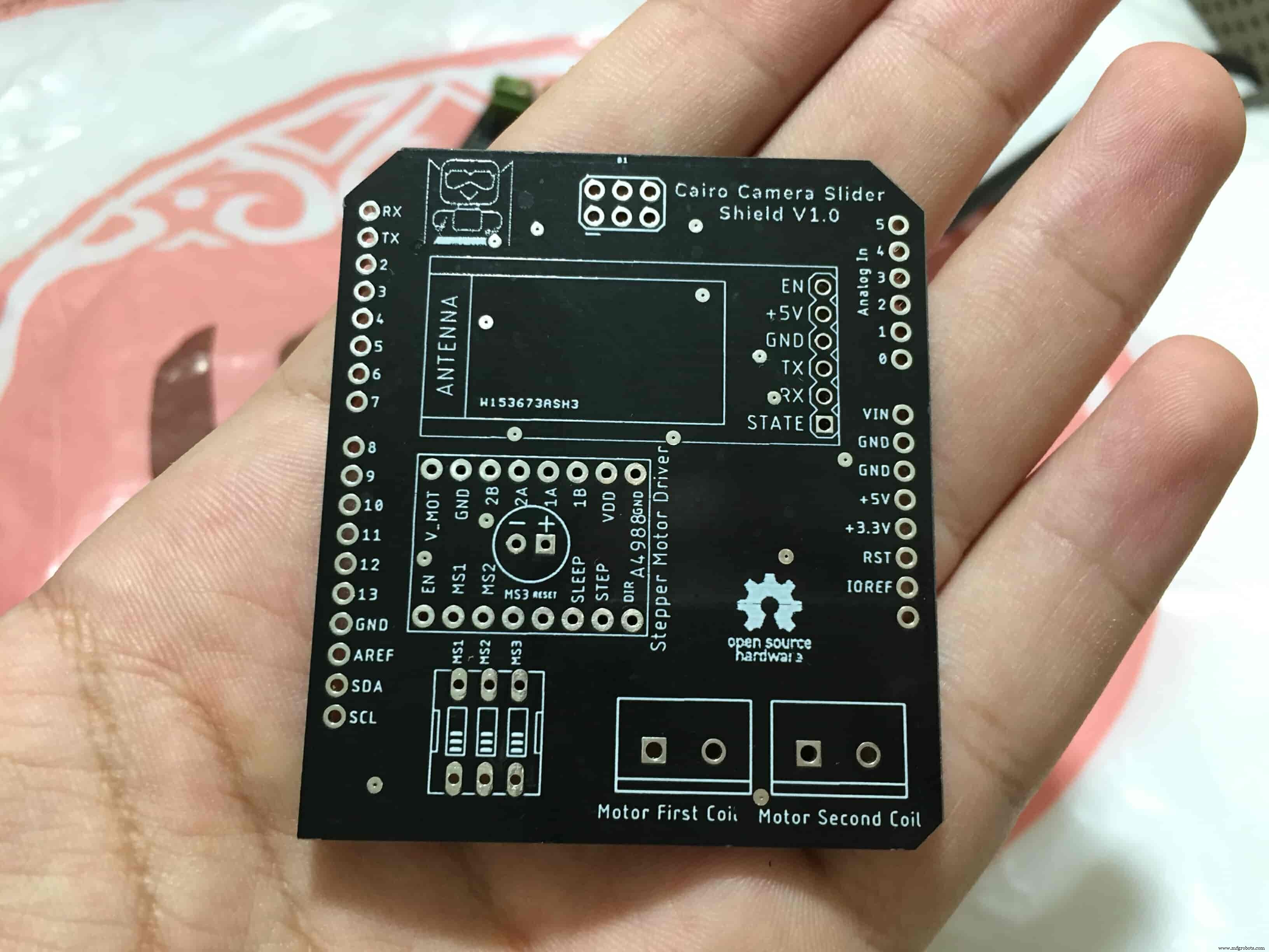
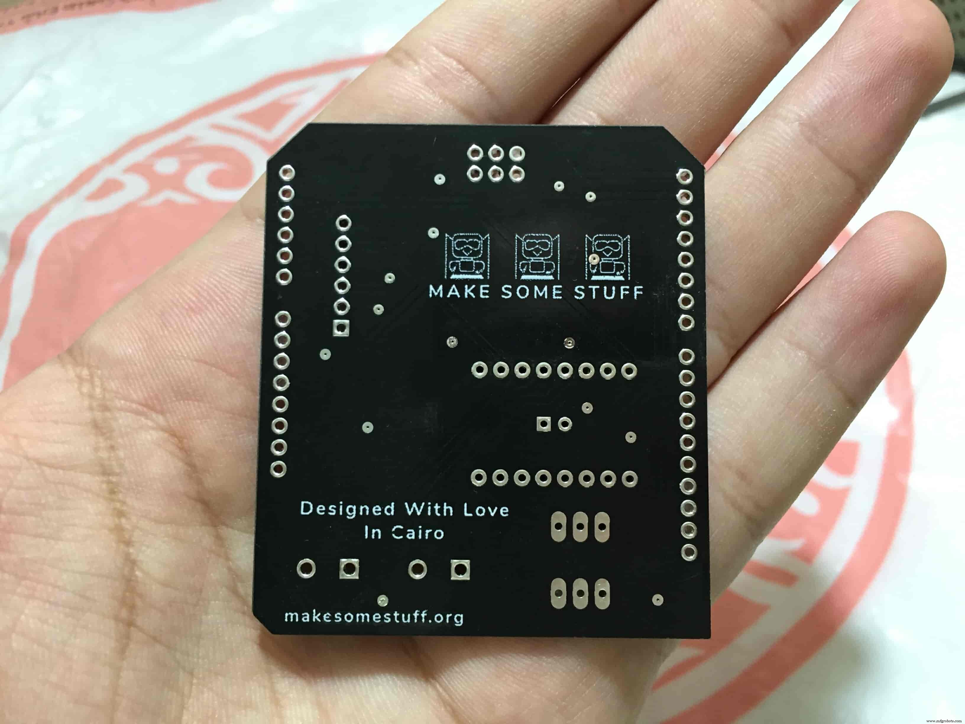
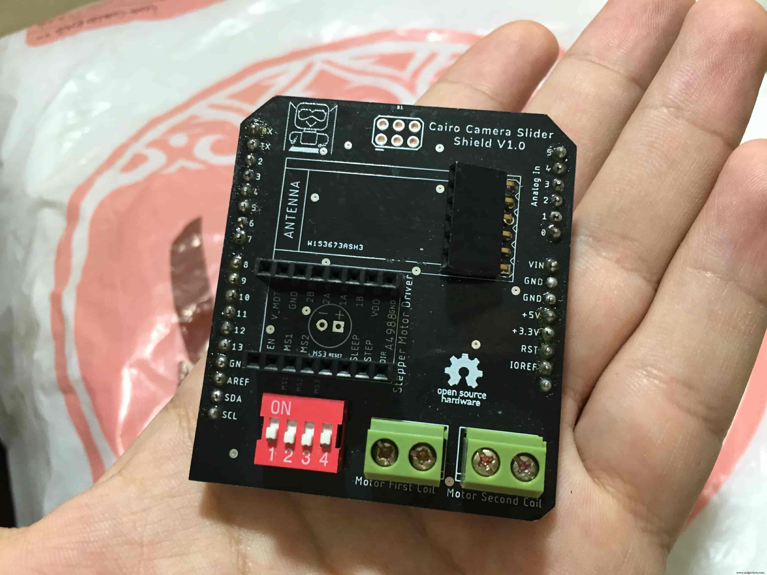
Schematic and PCB Fabrication
Man! I don’t like breadboarding a big circuit like this. So, I designed a super pretty Arduino UNO shield PCB board that keeps all my components in place without worrying about the jumper wires or even the connections. All you need to do is to place your component on the Arduino shield PCB, insert the HC-05 Bluetooth module, A4988 stepper motor driver, and the battery in their places. and install the shield on top of the Arduino board. that’s it!
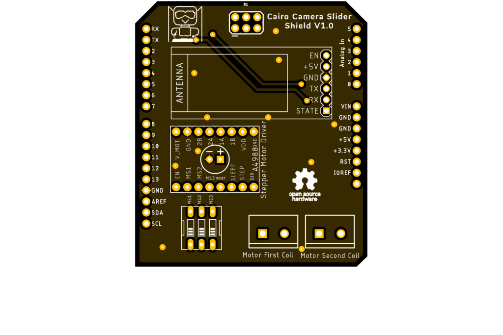
I fabricated my PCB at PCBWay the quality was very good, in a few days the package arrived in Egypt safely. and I paid just 5$ for the fabrication which is amazing. The coolest thing that I was able to check the order fabrication and processing status online on my account panel and track everything happening to my baby board like I was there inside the factory.
you can download the PCB design source files or even ordering the Cairo Camera Slider Arduino Shield PCB from the PCBWay website. PCB Source Files &Ordering

Arduino Code And Bluetooth Communication
/*
 TODO::Update the arduino program to Make the user able to choose the motor driver micro stepping mode. find and equation that helps to automatically adjust the the "steps" variable value.
 TODO::update the mobile app to ask the user on the beginning only about the [homing position(done), microstepping mode].
 TODO::Update the arduino program to make the code only iterates around the "homing position" &"microstepping mode" only once on the void setup() function.

 DATA::left arrow button sends --> 1.
 DATA::right arrow button sends --> 2.
 DATA::stop button sends --> 3.

 DATA::rail length (1cm - 1000cm) --> (201 - 1200).

 DATA::motor acceleration spinner Very High --> 14.
 DATA::motor acceleration spinner High --> 11
 DATA::motor acceleration spinner Medium --> 12
 DATA::motor acceleration spinner Low --> 13
 DATA::motor acceleration spinner Very Low --> 15

 DATA::motor speed slider (1 step/sec. - 4000 step/sec.) --> (5001 - 9000).

 DATA::delay start checkbox is true --> 7.
 DATA::delay start checkbox is false --> 8.

 DATA::left end homing --> 16.
 DATA::right end homing --> 17.

 DATA::Smooth movement Type --> 18.
 DATA::Very Smooth movement Type --> 19.

 1301 --> 2300
*/

#include
#include

#define stepPin 2
#define dirPin 3

bool homingPositionFlag =false;
int startupSetupFlag =0;
bool delayedStart =false;

int incomingData =0;
int movementDistance =50;
long steps =0; //50cm rail by default @1/8 microstepping.
int microStepResolution =0; //4 or 16
long railLength =0;
int sliderSpeed =10;

AccelStepper stepper(AccelStepper::DRIVER, stepPin, dirPin); //create an object. the pin "2" is the step pin, "3" is the direction pin.

void setup() {
 pinMode(stepPin, OUTPUT);
 pinMode(dirPin, OUTPUT);
 Serial.begin(9600);

 stepper.setMaxSpeed(10.00); //The fastest motor speed that can be reliably supported is about 4000 steps per second at a clock frequency of 16 MHz on Arduino such as Uno
 stepper.setAcceleration(500.00); //1600 (40%) (Medium Acceleration rate)

 while (startupSetupFlag <3) {
 if (Serial.available()> 1) {
 unsigned int dataOne =Serial.read();
 unsigned int dataOne1 =Serial.read();
 unsigned int incomingData =(dataOne1 * 256) + dataOne;

 //**************************************************************Motor Homing Part**************************************************
 if (incomingData ==16) { //left end homing position.
 stepper.setCurrentPosition(steps);
 homingPositionFlag =false;
 startupSetupFlag++;
 } else if (incomingData ==17) { //right end homing position.
 stepper.setCurrentPosition(-(steps));
 homingPositionFlag =true;
 startupSetupFlag++;
 }
 //**************************************************************microstep resolution Part**************************************************
 if (incomingData ==18) {
 microStepResolution =4; //50cm rail length @1/4 microstep resolution.
 startupSetupFlag++;
 } else if (incomingData ==19) {
 microStepResolution =16; //50cm rail length @1/16 microstep resolution.
 startupSetupFlag++;
 }

 if (incomingData>=1301 &&incomingData <=2300) {
 railLength =incomingData - 1300; //from raw data to cm.
 if (microStepResolution ==4) {
 steps =((6100L * railLength) / 50L);
 startupSetupFlag++;
 }
 else if (microStepResolution ==16) {
 steps =((25000L * railLength) / 50L);
 startupSetupFlag++;
 }
 }
 }
 //Serial.println(startupSetupFlag);
 }
 /*
 * *********** *********** **********For Debugging Purposes* *********** *********** **********
 Serial.print("rail length:");
 Serial.print(railLength);
 Serial.print(" number of steps:");
 Serial.print(steps);
 Serial.print(" Homing position:");
 Serial.print(stepper.currentPosition());
 Serial.print(" microstep resolution:");
 Serial.println(microStepResolution);*/
}

void loop() {

 if (Serial.available()> 1) {

 unsigned int dataOne =Serial.read();
 unsigned int dataOne1 =Serial.read();
 unsigned int incomingData =(dataOne1 * 256) + dataOne;
 //Serial.print("raw data:");
 //Serial.println(incomingData);

 //**************************************************************Motor Control Part**************************************************
 if (incomingData ==1 &&stepper.isRunning() ==false &&stepper.currentPosition() !=6050 &&homingPositionFlag ==true) {
 if (delayedStart ==true) { //use millis to delay 15 seconds.
 delay(15000); //wait 15 seconds.
 }
 stepper.setCurrentPosition(0);
 stepper.moveTo(steps); //from end to end (@ 1/4 step).
 homingPositionFlag =false;

 /*Serial.print("rail length:");
 Serial.print(railLength);
 Serial.print(" number of steps:");
 Serial.print(steps);
 Serial.print(" Homing position:");
 Serial.print(stepper.currentPosition());
 Serial.print(" microstep resolution:");
 Serial.println(microStepResolution);*/
 }

 else if (incomingData ==2 &&stepper.isRunning() ==false &&stepper.currentPosition() !=-6050 &&homingPositionFlag ==false) {
 if (delayedStart ==true) { //use millis to delay 15 seconds.
 delay(15000); //wait 15 seconds.
 }
 stepper.setCurrentPosition(0);
 stepper.moveTo(-(steps)); //from end to end (@ 1/4 step).
 homingPositionFlag =true;

 /*Serial.print("rail length:");
 Serial.print(railLength);
 Serial.print(" number of steps:");
 Serial.print(steps);
 Serial.print(" Homing position:");
 Serial.print(stepper.currentPosition());
 Serial.print(" microstep resolution:");
 Serial.println(microStepResolution);*/
 }

 else if (incomingData ==3 &&stepper.isRunning() ==true) {
 homing();
 }

 //**************************************************************Set Max. Speed Part**************************************************
 else if (incomingData>=5001 &&incomingData <=9000) {
 sliderSpeed =incomingData - 5000;
 stepper.setMaxSpeed(sliderSpeed);
 }

 //**************************************************************Set Delayed Start Part**************************************************
 else if (incomingData ==7) { //delayed start (15 seconds) is checked "true"
 delayedStart =true;
 }
 else if (incomingData ==8) { //delayed start (15 seconds) is not checked "false"
 delayedStart =false;
 }

 //**************************************************************Set movement distance Part**************************************************
 else if (incomingData>=201 &&incomingData <=1200) { //convertin from rail length into number of steps. (upto 10 meters)
 movementDistance =incomingData - 200; //from raw data to cm.
 if (microStepResolution ==4) {
 steps =((6100L * movementDistance) / 50L);
 }
 else if (microStepResolution ==16) {
 steps =((25000L * movementDistance) / 50L);
 }
 /*Serial.print("rail length:");
 Serial.print(movementDistance);
 Serial.print(" number of steps:");
 Serial.println(steps);*/
 }

 //**************************************************************Set Acceleration Part**************************************************
 else if (incomingData ==11 &&stepper.isRunning() ==false) { //HIGH
 stepper.setAcceleration(3000);
 }

 else if (incomingData ==12 &&stepper.isRunning() ==false) { //Medium
 stepper.setAcceleration(1000);
 }

 else if (incomingData ==13 &&stepper.isRunning() ==false) { //Low
 stepper.setAcceleration(500);
 }

 else if (incomingData ==14 &&stepper.isRunning() ==false) { //Very High
 stepper.setAcceleration(4000);
 }

 else if (incomingData ==15 &&stepper.isRunning() ==false) { //Very Low
 stepper.setAcceleration(10);
 }
 }
 stepper.run();
}

void homing() {
 if (stepper.currentPosition()> 0) {
 homingPositionFlag =true;
 } else {
 homingPositionFlag =false;
 }
 stepper.moveTo(0);
}
Code Logic
We’re using the amazing AccelStepper Arduino library that provides an object-oriented interface for 2, 3, 4 pins stepper motors to control it’s movement precisely.
#define stepPin 2
#define dirPin 3

bool homingPositionFlag =false;

int startupSetupFlag =0;
bool delayedStart =false;

int incomingData =0;
int movementDistance =50;

long steps =0; //50cm rail by default @1/8 microstepping.
int microStepResolution =0; //4 or 16

long railLength =0;
int sliderSpeed =10;

AccelStepper stepper(AccelStepper::DRIVER, stepPin, dirPin); //create an object. the pin "2" is the step pin, "3" is the direction pin.
when you open the mobile app and get connected to the Cairo camera slider it will ask you about the micro-stepping mode that you set the A4988 motor driver to work at. it’s very important to choose the correct micro-stepping mode. The Cairo camera slider only supports the 1/4 and 1/16 micro-step resolution. If you chose a wrong micro-step mode it will affect the distance calculations causing the camera carriage to hit the slider limits. So, be careful!
- 1/4 --> Smooth.
- 1/16 --> Very Smooth.

//**************************************************************microstep resolution Part**************************************************
if (incomingData ==18) {
 microStepResolution =4; //50cm rail length @1/4 microstep resolution.
 startupSetupFlag++;

} else if (incomingData ==19) {
 microStepResolution =16; //50cm rail length @1/16 microstep resolution.
 startupSetupFlag++;
}
It sets the camera slider homing if it’s left or right side homing. the homing position, once you click on right or left side homing a specific piece of data will get sent from the mobile app to the Arduino board according to the homing position that you have chosen.

void setup() {
 pinMode(stepPin, OUTPUT);
 pinMode(dirPin, OUTPUT);
 Serial.begin(9600);

 stepper.setMaxSpeed(10.00); //The fastest motor speed that can be reliably supported is about 4000 steps per second at a clock frequency of 16 MHz on Arduino such as Uno
 stepper.setAcceleration(500.00); //1600 (40%) (Medium Acceleration rate)

 while (startupSetupFlag <3) {
 if (Serial.available()> 1) {
 unsigned int dataOne =Serial.read();
 unsigned int dataOne1 =Serial.read();
 unsigned int incomingData =(dataOne1 * 256) + dataOne;

 //**************************************************************Motor Homing Part**************************************************
 if (incomingData ==16) { //left end homing position.
 stepper.setCurrentPosition(steps);
 homingPositionFlag =false;
 startupSetupFlag++;
 }
 else if (incomingData ==17) { //right end homing position.
 stepper.setCurrentPosition(-(steps));
 homingPositionFlag =true;
 startupSetupFlag++;
 }
now it sets how many steps should the stepper motor moves without hitting the camera carriage with the camera slider right or left legs. it reads and saves the rail length according to the value that the user enters in the mobile app. So, depending on the micro-step resolution that the user selected before, and the rail length I can calculate the number of steps that the motor should rotate to reach the limits of the slider rail without hitting the right or left legs.

if (incomingData>=1301 &&incomingData <=2300) {
 railLength =incomingData - 1300; //from raw data to cm.
 if (microStepResolution ==4) {
 steps =((6100L * railLength) / 50L);
 startupSetupFlag++;
 }
 else if (microStepResolution ==16) {
 steps =((25000L * railLength) / 50L);
 startupSetupFlag++;
 }
 }
 }
 //Serial.println(startupSetupFlag);
 }
inside the loop function, it reads the mobile app incoming data and according to these data it takes different actions, like moving the stepper motor clockwise, moving anti-clockwise, stop and return back to the starting point, and changing the traveling speed, so on…
void loop() {

 if (Serial.available()> 1) {

 unsigned int dataOne =Serial.read();
 unsigned int dataOne1 =Serial.read();
 unsigned int incomingData =(dataOne1 * 256) + dataOne;
 //Serial.print("raw data:");
 //Serial.println(incomingData);

 //**************************************************************Motor Control Part**************************************************
 if (incomingData ==1 &&stepper.isRunning() ==false &&stepper.currentPosition() !=6050 &&homingPositionFlag ==true) {
 if (delayedStart ==true) { //use millis to delay 15 seconds.
 delay(15000); //wait 15 seconds.
 }
 stepper.setCurrentPosition(0);
 stepper.moveTo(steps); //from end to end (@ 1/4 step).
 homingPositionFlag =false;

 /*Serial.print("rail length:");
 Serial.print(railLength);
 Serial.print(" number of steps:");
 Serial.print(steps);
 Serial.print(" Homing position:");
 Serial.print(stepper.currentPosition());
 Serial.print(" microstep resolution:");
 Serial.println(microStepResolution);*/
 }

 else if (incomingData ==2 &&stepper.isRunning() ==false &&stepper.currentPosition() !=-6050 &&homingPositionFlag ==false) {
 if (delayedStart ==true) { //use millis to delay 15 seconds.
 delay(15000); //wait 15 seconds.
 }
 stepper.setCurrentPosition(0);
 stepper.moveTo(-(steps)); //from end to end (@ 1/4 step).
 homingPositionFlag =true;

 /*Serial.print("rail length:");
 Serial.print(railLength);
 Serial.print(" number of steps:");
 Serial.print(steps);
 Serial.print(" Homing position:");
 Serial.print(stepper.currentPosition());
 Serial.print(" microstep resolution:");
 Serial.println(microStepResolution);*/
 }

 else if (incomingData ==3 &&stepper.isRunning() ==true) {
 homing();
 }

 //**************************************************************Set Max. Speed Part**************************************************
 else if (incomingData>=5001 &&incomingData <=9000) {
 sliderSpeed =incomingData - 5000;
 stepper.setMaxSpeed(sliderSpeed);
 }

 //**************************************************************Set Delayed Start Part**************************************************
 else if (incomingData ==7) { //delayed start (15 seconds) is checked "true"
 delayedStart =true;
 }
 else if (incomingData ==8) { //delayed start (15 seconds) is not checked "false"
 delayedStart =false;
 }

 //**************************************************************Set movement distance Part**************************************************
 else if (incomingData>=201 &&incomingData <=1200) { //convertin from rail length into number of steps. (upto 10 meters)
 movementDistance =incomingData - 200; //from raw data to cm.
 if (microStepResolution ==4) {
 steps =((6100L * movementDistance) / 50L);
 }
 else if (microStepResolution ==16) {
 steps =((25000L * movementDistance) / 50L);
 }
 /*Serial.print("rail length:");
 Serial.print(movementDistance);
 Serial.print(" number of steps:");
 Serial.println(steps);*/
 }

 //**************************************************************Set Acceleration Part**************************************************
 else if (incomingData ==11 &&stepper.isRunning() ==false) { //HIGH
 stepper.setAcceleration(3000);
 }

 else if (incomingData ==12 &&stepper.isRunning() ==false) { //Medium
 stepper.setAcceleration(1000);
 }

 else if (incomingData ==13 &&stepper.isRunning() ==false) { //Low
 stepper.setAcceleration(500);
 }

 else if (incomingData ==14 &&stepper.isRunning() ==false) { //Very High
 stepper.setAcceleration(4000);
 }

 else if (incomingData ==15 &&stepper.isRunning() ==false) { //Very Low
 stepper.setAcceleration(10);
 }
 }
 stepper.run();
}

void homing() {
 if (stepper.currentPosition()> 0) {
 homingPositionFlag =true;
 } else {
 homingPositionFlag =false;
 }
 stepper.moveTo(0);
}
Cairo Camera Slider User Guide &troubleshooting
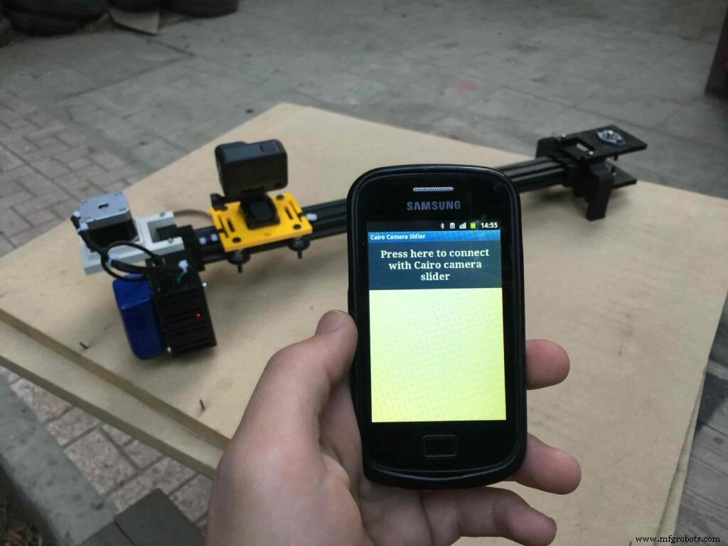
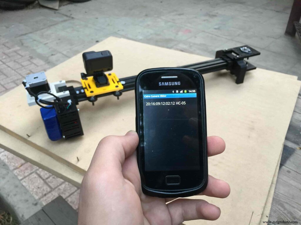
After connecting the 12V power source to the Arduino UNO board that distributes power to the Cairo camera slider Arduino shield as well, turn on the Bluetooth on your mobile, search for new devices, pair with the HC-05 device, and open the mobile app then press on the “Press here to connect with Cairo camera slider” button. It will show up the menu of the paired Bluetooth devices, select the HC-05 Bluetooth device.
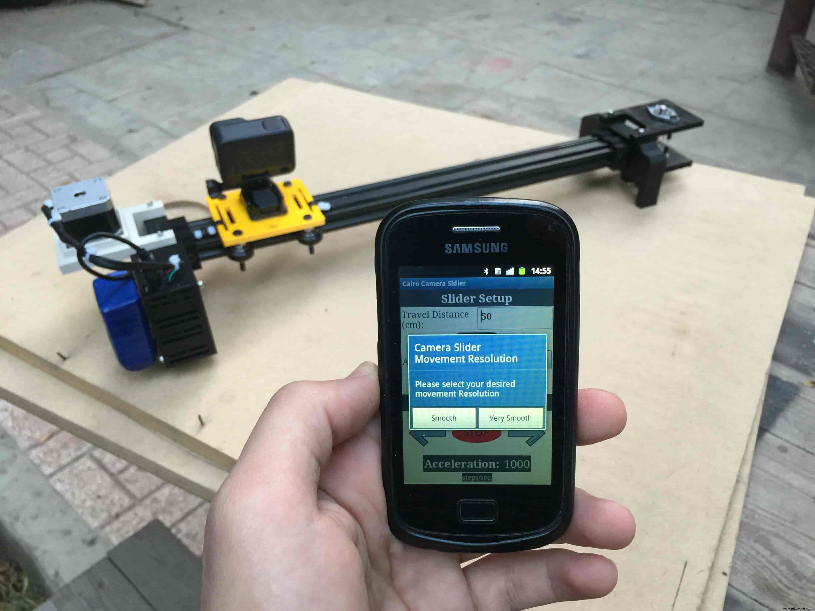
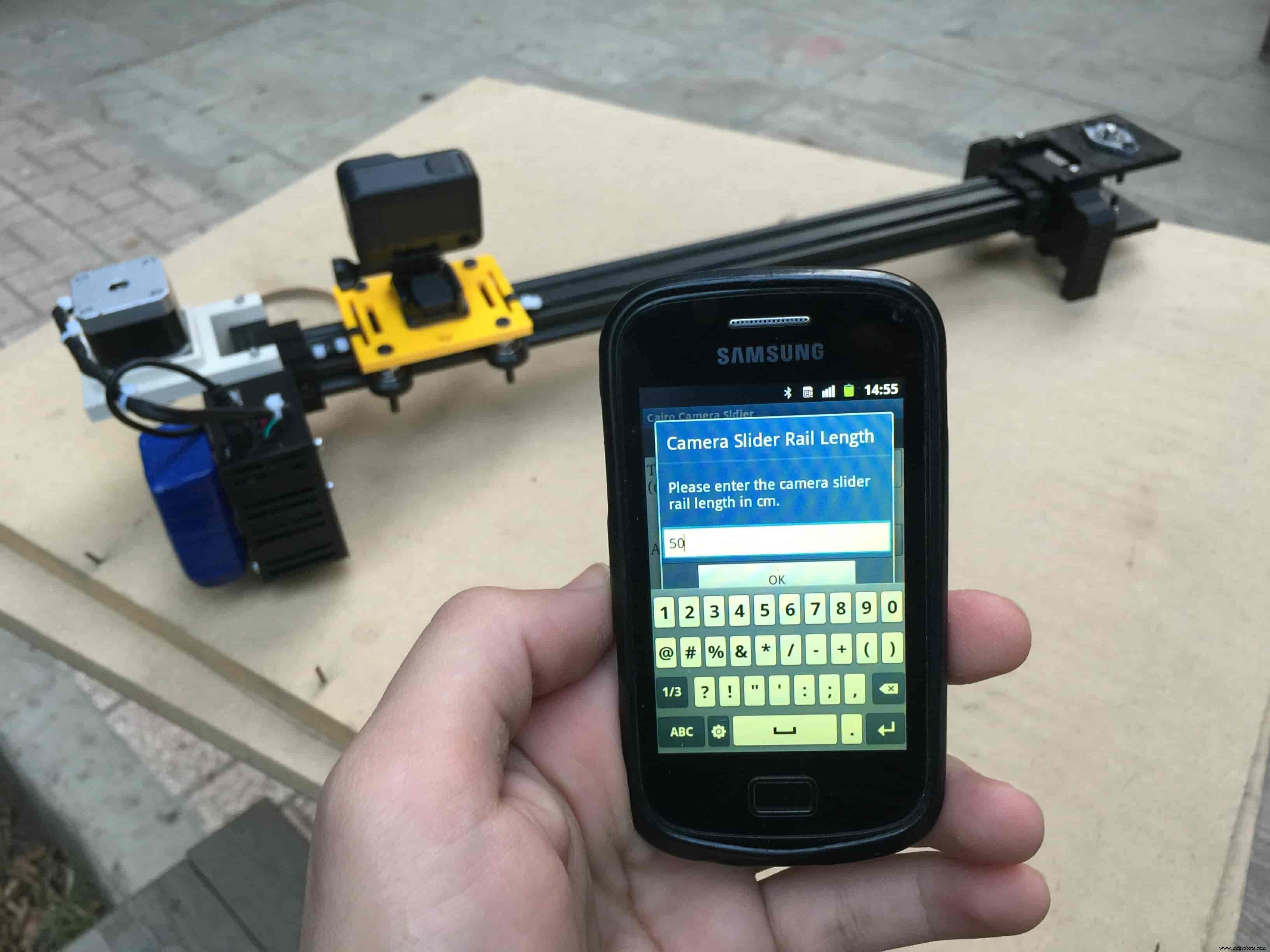
After connecting successfully with the Control board, the mobile app will ask you some questions to set up some parameters. First question will ask you about the micro-step resolution of the stepper motor driver if it’s smooth(1/4 micro-step), or very smooth(1/16 micro-step). select the mode According to the micro-stepping resolution mode that you set the A4988 driver at. If you selected a wrong mode The Cairo camera slider will not work correctly.
Then, it will ask you about the aluminum rail length that you are using in your camera slider. Enter the distance in CM. in my case I’m using a 50cm rail length.
Lastly, it will ask you about the camera carriage homing position, It’s very important to place the camera carriage on one of the two rail ends, the right end or the left end. In my case, the camera carriage is on the left end. So, I selected the left end homing.
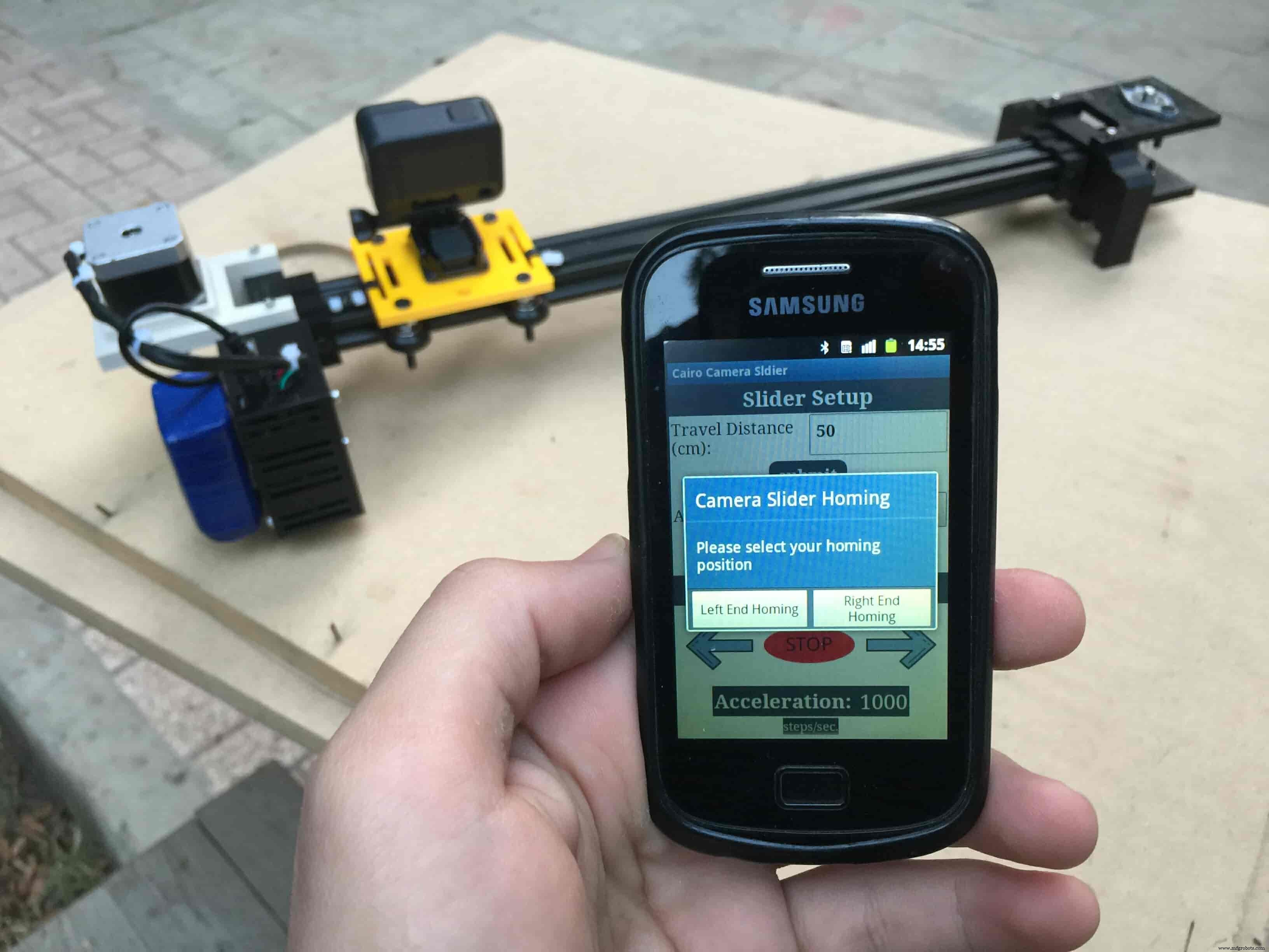
If you started the Cairo camera slider and the camera carriage is on the middle of the rail or not on one of the two rail ends it will cause the carriage to hit the limits when it moves.
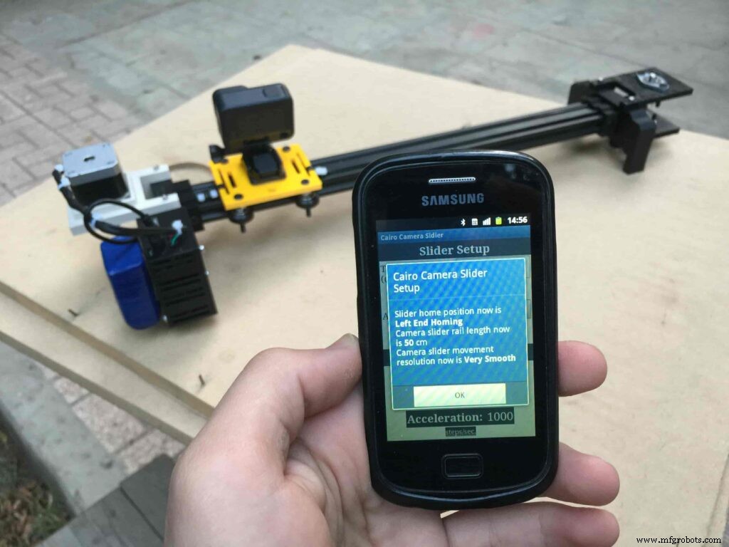
After you finish the set-up process, It will show you the parameters that you have set. And once you click OK, you will be ready to play around with your lovely Cairo camera slider.
Cairo Camera Slider In-Action
Code
- Cairo Camera Slider Final Code
Cairo Camera Slider Final CodeArduino
/* TODO::Update the arduino program to Make the user able to choose the motor driver micro stepping mode. find and equation that helps to automatically adjust the the "steps" variable value. TODO::update the mobile app to ask the user on the beginning only about the [homing position(done), microstepping mode]. TODO::Update the arduino program to make the code only iterates around the "homing position" &"microstepping mode" only once on the void setup() function. DATA::left arrow button sends --> 1. DATA::right arrow button sends --> 2. DATA::stop button sends --> 3. DATA::rail length (1cm - 1000cm) --> (201 - 1200). DATA::motor acceleration spinner Very High --> 14. DATA::motor acceleration spinner High --> 11 DATA::motor acceleration spinner Medium --> 12 DATA::motor acceleration spinner Low --> 13 DATA::motor acceleration spinner Very Low --> 15 DATA::motor speed slider (1 step/sec. - 4000 step/sec.) --> (5001 - 9000). DATA::delay start checkbox is true --> 7. DATA::delay start checkbox is false --> 8. DATA::left end homing --> 16. DATA::right end homing --> 17. DATA::Smooth movement Type --> 18. DATA::Very Smooth movement Type --> 19. 1301 --> 2300*/#include#include #define stepPin 2#define dirPin 3bool homingPositionFlag =false;int startupSetupFlag =0;bool delayedStart =false;int incomingData =0;int movementDistance =50;long steps =0; //50cm rail by default @1/8 microstepping.int microStepResolution =0; //4 or 16long railLength =0;int sliderSpeed =10;AccelStepper stepper(AccelStepper::DRIVER, stepPin, dirPin); //create an object. the pin "2" is the step pin, "3" is the direction pin.void setup() { pinMode(stepPin, OUTPUT); pinMode(dirPin, OUTPUT); Serial.begin(9600); stepper.setMaxSpeed(10.00); //The fastest motor speed that can be reliably supported is about 4000 steps per second at a clock frequency of 16 MHz on Arduino such as Uno stepper.setAcceleration(500.00); //1600 (40%) (Medium Acceleration rate) while (startupSetupFlag <3) { if (Serial.available()> 1) { unsigned int dataOne =Serial.read(); unsigned int dataOne1 =Serial.read(); unsigned int incomingData =(dataOne1 * 256) + dataOne; //**************************************************************Motor Homing Part************************************************** if (incomingData ==16) { //left end homing position. stepper.setCurrentPosition(steps); homingPositionFlag =false; startupSetupFlag++; } else if (incomingData ==17) { //right end homing position. stepper.setCurrentPosition(-(steps)); homingPositionFlag =true; startupSetupFlag++; } //**************************************************************microstep resolution Part************************************************** if (incomingData ==18) { microStepResolution =4; //50cm rail length @1/4 microstep resolution. startupSetupFlag++; } else if (incomingData ==19) { microStepResolution =16; //50cm rail length @1/16 microstep resolution. startupSetupFlag++; } if (incomingData>=1301 &&incomingData <=2300) { railLength =incomingData - 1300; //from raw data to cm. if (microStepResolution ==4) { steps =((6100L * railLength) / 50L); startupSetupFlag++; } else if (microStepResolution ==16) { steps =((25000L * railLength) / 50L); startupSetupFlag++; } } } //Serial.println(startupSetupFlag); } /* * *********** *********** **********For Debugging Purposes* *********** *********** ********** Serial.print("rail length:"); Serial.print(railLength); Serial.print(" number of steps:"); Serial.print(steps); Serial.print(" Homing position:"); Serial.print(stepper.currentPosition()); Serial.print(" microstep resolution:"); Serial.println(microStepResolution);*/}void loop() { if (Serial.available()> 1) { unsigned int dataOne =Serial.read(); unsigned int dataOne1 =Serial.read(); unsigned int incomingData =(dataOne1 * 256) + dataOne; //Serial.print("raw data:"); //Serial.println(incomingData); //**************************************************************Motor Control Part************************************************** if (incomingData ==1 &&stepper.isRunning() ==false &&stepper.currentPosition() !=6050 &&homingPositionFlag ==true) { if (delayedStart ==true) { //use millis to delay 15 seconds. delay(15000); //wait 15 seconds. } stepper.setCurrentPosition(0); stepper.moveTo(steps); //from end to end (@ 1/4 step). homingPositionFlag =false; /*Serial.print("rail length:"); Serial.print(railLength); Serial.print(" number of steps:"); Serial.print(steps); Serial.print(" Homing position:"); Serial.print(stepper.currentPosition()); Serial.print(" microstep resolution:"); Serial.println(microStepResolution);*/ } else if (incomingData ==2 &&stepper.isRunning() ==false &&stepper.currentPosition() !=-6050 &&homingPositionFlag ==false) { if (delayedStart ==true) { //use millis to delay 15 seconds. delay(15000); //wait 15 seconds. } stepper.setCurrentPosition(0); stepper.moveTo(-(steps)); //from end to end (@ 1/4 step). homingPositionFlag =true; /*Serial.print("rail length:"); Serial.print(railLength); Serial.print(" number of steps:"); Serial.print(steps); Serial.print(" Homing position:"); Serial.print(stepper.currentPosition()); Serial.print(" microstep resolution:"); Serial.println(microStepResolution);*/ } else if (incomingData ==3 &&stepper.isRunning() ==true) { homing(); } //**************************************************************Set Max. Speed Part************************************************** else if (incomingData>=5001 &&incomingData <=9000) { sliderSpeed =incomingData - 5000; stepper.setMaxSpeed(sliderSpeed); } //**************************************************************Set Delayed Start Part************************************************** else if (incomingData ==7) { //delayed start (15 seconds) is checked "true" delayedStart =true; } else if (incomingData ==8) { //delayed start (15 seconds) is not checked "false" delayedStart =false; } //**************************************************************Set movement distance Part************************************************** else if (incomingData>=201 &&incomingData <=1200) { //convertin from rail length into number of steps. (upto 10 meters) movementDistance =incomingData - 200; //from raw data to cm. if (microStepResolution ==4) { steps =((6100L * movementDistance) / 50L); } else if (microStepResolution ==16) { steps =((25000L * movementDistance) / 50L); } /*Serial.print("rail length:"); Serial.print(movementDistance); Serial.print(" number of steps:"); Serial.println(steps);*/ } //**************************************************************Set Acceleration Part************************************************** else if (incomingData ==11 &&stepper.isRunning() ==false) { //HIGH stepper.setAcceleration(3000); } else if (incomingData ==12 &&stepper.isRunning() ==false) { //Medium stepper.setAcceleration(1000); } else if (incomingData ==13 &&stepper.isRunning() ==false) { //Low stepper.setAcceleration(500); } else if (incomingData ==14 &&stepper.isRunning() ==false) { //Very High stepper.setAcceleration(4000); } else if (incomingData ==15 &&stepper.isRunning() ==false) { //Very Low stepper.setAcceleration(10); } } stepper.run();}void homing() { if (stepper.currentPosition()> 0) { homingPositionFlag =true; } else { homingPositionFlag =false; } stepper.moveTo(0);}
Custom parts and enclosures
Cairo Camera Slider STLs
CAD file on thingiverse.comSchematics

製造プロセス