


コンパニオンIC
コンポーネントと消耗品
>  |
| × | 1 | |||
 |
| × | 1 | |||
 |
| × | 4 | |||
 |
| × | 1 | |||
 |
| × | 2 | |||
 |
| × | 3 | |||
 |
| × | 4 | |||
 |
| × | 2 | |||
 |
| × | 1 | |||
 |
| × | 1 |
必要なツールとマシン
>  |
| |||
 |
|
このプロジェクトについて
<図> 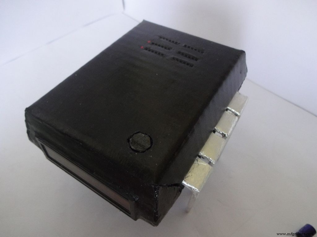 <図>
<図>  <図>
<図> 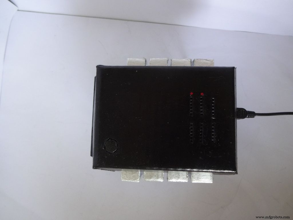
コンパニオンICは、非常にかっこいい時計+抵抗計+静電容量計+ダイオードテスターです。 ICのピン1を押して電源を入れてください!コンポーネントの迅速なテストと時間を確認するために、これを作業台に保管してください。作業台の近くに電源がある場合は、バッテリーまたはUSBで実行できます。
私はいつもプロジェクトを公開したかったのですが、今までユニークなものを見つけることはありませんでした!いくつかのコンデンサをテストして、それらが故障しているかどうかを確認したいと思ったときに、このアイデアが思い浮かびました。マルチメータしかありませんでしたが、静電容量測定機能はありませんでした。それについて調べた後、私はArduinoがこれを行うことができることを知りました。作ることにしましたが、Arduinoの未使用のピンを見るのはあまり満足のいくものではなかったので、オートレンジ抵抗計、クイックLED /ダイオードテスター、RTCクロックも追加することにしました!また、コンポーネントを接続してプローブを使用せずに直接値を測定することも望んでいました。デザインはユニークでなければならなかったので、ブレインストーミングを行った後、ICデザインが作成されました!
編集(2016年7月1日):オプションの導通テストが追加されました。コメントセクションをご覧ください。
この記事では、私がこれをどのように作成したか、そしてあなたも自分でこれを作成する方法について詳しく説明します。初心者向けで、Arduino / Electronicsの経験が2〜3週間あれば、誰でもこれを作成できます!
デザインは変更可能であり、要件に応じて新しい機能を削除/追加できます。段ボールでケースを作りましたが、スキルがあれば木や3Dプリントで作れます。
私は自分が行ったすべてのステップで写真を撮って添付しようとしました(各ステップでたくさん!)。これらのほとんどは、私が最高の角度/光を得るまで何度も撮影されましたが、それでもいくつかは、すべてを両手で保持するのが難しい場合があるため、少しぼやけています。
私はコード全体と配線を細かく分割して、それをどのように作成したかを説明しました。含まれているコードは、コメントが多く、適切にインデントされています。先に進むと。すべてのコードと配線を段階的に組み合わせて、最終的なICを作成します。これは、誰もがそれを明確に理解するのに役立つはずです。そうでない場合は、コメントでお知らせください。
作らないと決めたとしても、ブレッドボードで試してみるか、少なくとも一度読んでみてください。ここで学ぶことができ、いつか役立つ方法やトリックなどが必要です(真剣に、いつかはわかりません)クリックします!)
ステップ1:必要なツールとコンポーネント <図>
 <図>
<図>  <図>
<図> 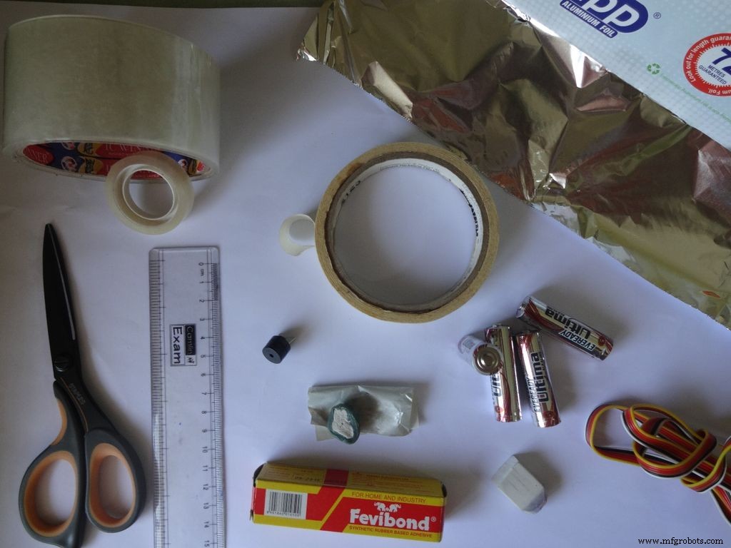 <図>
<図> 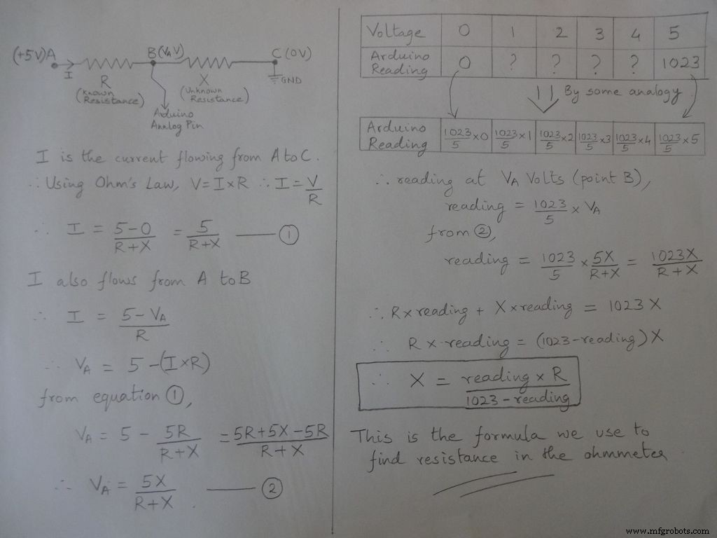
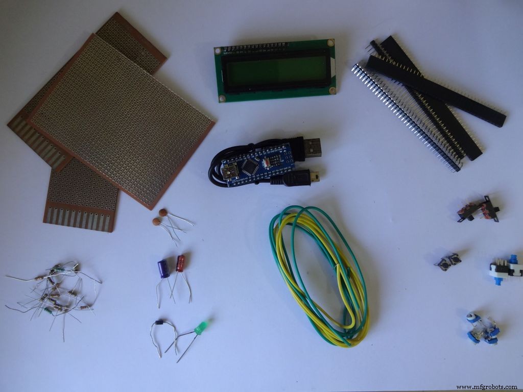
使用されているコンポーネントと材料のリスト(参照用のストアリンク):
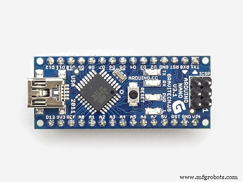
- 1x Arduino Nano V3、 CH340Gでクローンを使用しました --ebay
- ミニUSBケーブル ArduinoNanoの場合-ミニ マイクロではありません !
- 段ボール- 厚さ約2mmの梱包箱を使用しました。近所の人や友達に聞いて、見つからない場合は清掃に行きましょう。
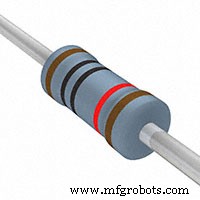
- 4x 10kオーム抵抗 -簡単に入手可能
- 2x 220オーム抵抗 -簡単に入手可能
- 1x (1k、4.7k、47k、100k)オーム抵抗 -簡単に入手可能
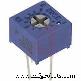
- 1x小型 10kオームポテンショメータ、 LCDのコントラスト制御用...どんな小さなサイズでも機能します .-- ebay
- 2xマイクロプッシュボタン、 リセットおよびモード変更ボタンの場合、ブレッドボードで使用する一般的なボタン。
- 3x小型スライドスイッチ 、バックライトを有効にするには、ピン0と1、シリアルを使用している間はこれらのピンを無効にする必要があります --ebay
- 1xメンテナンス/トグル/ ラッチプッシュスイッチ、 電源スイッチ用 --ebay
- 一部のコンデンサ、ダイオード、LEDはテスト用ですが、いつか使用する予定です。
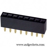
- 4x メスヘッダーピンストリップ --ebay(ストリップあたり40ピン)
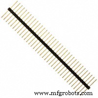
- 2x オスヘッダーピンストリップ --ebay(ストリップあたり40ピン)
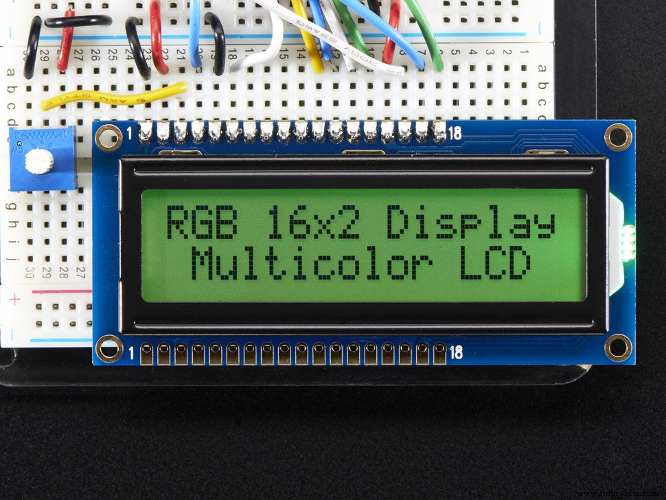
- 1x 16x2文字LCD --ebay
- 1x DS3231またはDS1307RTCモジュール (RTCはReal Time Clockの略です)- ebayから安いものを購入しないでください。これらは偽のチップを使用しており、不正確です。これ、これまたはこれを購入します。これらのいずれかが機能します。
- 4x AA電池(またはAAA。 AAAの使用ははるかに簡単ですが、バッテリー容量は少なくなります)
- 1x 4 AA(またはAAA)バッテリーホルダー 、フラットバリアント --ebay
- 一本鎖線 、ブレッドボードに使用されるもの、22ゲージ
- リボンケーブル (またはいくつかの細いツイストペア線を使用できます) --ebay
- 2x 小さなナットとボルト -古いMeccanoセットのものを使用しました(ボルトの長さは1.3cm)
- 黒のアクリル絵の具とブラシ
必要なツール:
- はんだごて
- はんだ
- 芯/ブレードのはんだ除去(めちゃくちゃにしたときのために!)
- グルーガン
- マスキングテープ
- セロテープ、透明
- ワイヤーストリッパー、ニッパー
- シャープボックスカッター
- はさみの鋭いペア
ステップ2:抵抗計-コンセプト <図>
<図> 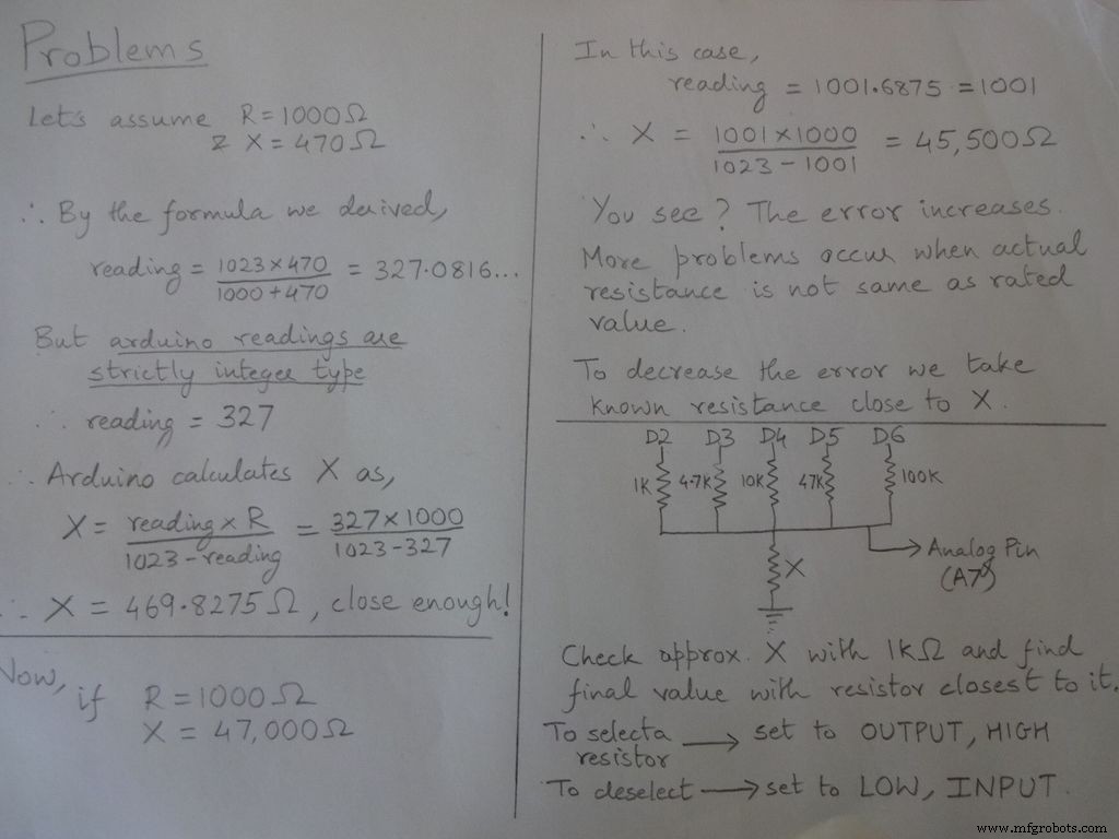 <図>
<図> 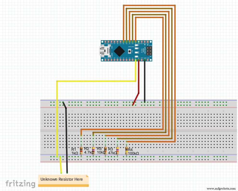
抵抗を測定する基本的な考え方は、分圧器に由来します。
抵抗値は変更可能で、r1、r2などの値を変更します。それに応じて範囲(自動レンジ用)も設定します。以下のコードを参照し、最後のファイルからダウンロードして、ブレッドボードで抵抗計をテストします
Nanoを初めて設定する場合は、CH340Gドライバーをここからダウンロードできます。Windows7、8、8.1、および10で動作します。Macユーザーはここを確認してください。
ボードメニューで「ArduinoNano」を選択し、正しいCOMポートを選択します。アップロード!
コード
//抵抗を見つけるために使用されるアナログピンApin =7; // r1からr5floatの値r1 =1000; float r2 =4700; float r3 =10000; float r4 =47000; float r5 =100000; / / r1からr5intへのピンr1_pin =2; int r2_pin =3; int r3_pin =4; int r4_pin =5; int r5_pin =6; float reading =0; //アナログピンから読み取り、herefloat R =0に保存します。 //不明を計算してhereStringfinalRに格納します; // unitsintcasenoとともに表示される最終値; //デバッグのために、ケース番号を格納します//範囲全体をケースに分割し、それぞれに番号を割り当てます。合計5つのケース// case1:2850未満// case2:2850〜7350 // case3:7350〜28500 // case4:28500〜73500 // case5:73500以上#include // floatをstringに変換するために必要で、String(float、n)関数があります。以下に説明します。voidsetup(){Serial.begin(9600);} void loop(){//最初に1kOhm抵抗を使用して未知の抵抗を見つけます//したがって、R2、R3、R4、およびR5を無効にしますdigitalWrite(r2_pin、LOW); // INPUTとして設定する前に各ピンをLOWに切り替えますpinMode(r2_pin、INPUT); // HIGHで内部プルアップ抵抗が有効になったときにINPUTにすると、digitalWrite(r3_pin、LOW); pinMode(r3_pin、INPUT); digitalWrite(r4_pin、LOW); pinMode(r4_pin、INPUT); digitalWrite(r5_pin、LOW); pinMode(r5_pin、INPUT); pinMode(r1_pin、OUTPUT); digitalWrite(r1_pin、HIGH); //抵抗を読み取って計算しますreading =analogRead(Apin); R =(reading * r1)/(1023-reading); //値<2850の場合、finalR =value(using 1kOhm)if(R <2850){caseno =1; if(R <1000){//値が1000未満の場合は、「kOhm」ではなく「Ohm」を使用しますfinalR =String(R、2)+ "Ohm"; // String(float、n)floatを10進数の後にn桁の文字列に変換します//値の後に "Ohm"を文字列に付加し、 '+'はここで2つの文字列を結合します} else {// use "kOhm R =R / 1000; finalR =String(R、2)+ "kOhm";}} // 2850〜7350の値の場合、4.7kOhmで取得した値を使用else if(R> =2850 &&R <7350){caseno =2; digitalWrite(r1_pin 、LOW); // 4.7kOhmのみを有効にするpinMode(r1_pin、INPUT); digitalWrite(r3_pin、LOW); pinMode(r3_pin、INPUT); digitalWrite(r4_pin、LOW); pinMode(r4_pin、INPUT); digitalWrite(r5_pin、LOW ); pinMode(r5_pin、INPUT); pinMode(r2_pin、OUTPUT); digitalWrite(r2_pin、HIGH); reading =analogRead(Apin); R =(reading * r2)/(1023-reading)/ 1000; finalR =String( R、2)+ "kOhm";} // 7350〜28500の値の場合、10kOhmで取得した値を使用else if(R> =7350 &&R <28500){caseno =3; digitalWrite(r1_pin、LOW); pinMode( r1_pin、INPUT); digitalWrite(r2_pin、LOW); pinMode(r2_pin、INPUT); digitalWrite(r4_pin、LOW); pinMode(r4_pin、INPUT); digitalWrite(r5_pin、LOW); pinMode(r5_pin、INPUT); pinMode(r3_pin、OUTPUT); digitalWrite(r3_pin、HIGH); reading =analogRead(Apin); R =(reading * r3)/(1023-reading)/ 1000; finalR =String(R、2)+ "kOhm"; } // 28500〜73500の値の場合、47kOhmによって取得された値を使用しますelse if(R> =28500 &&R <73500){caseno =4; digitalWrite(r1_pin、LOW); pinMode(r1_pin、INPUT); digitalWrite(r2_pin、LOW); pinMode(r2_pin、INPUT); digitalWrite(r3_pin、LOW); pinMode(r3_pin、INPUT); digitalWrite(r5_pin、LOW); pinMode(r5_pin、INPUT); pinMode(r4_pin、OUTPUT); digitalWrite(r4_pin、HIGH); reading =analogRead(Apin); R =(reading * r4)/(1023-reading)/ 1000; finalR =String(R、2)+ "kOhm"; } // 73500を超える値の場合、100kOhmによって取得された値を使用しますelse if(R> =73500){caseno =5; digitalWrite(r1_pin、LOW); pinMode(r1_pin、INPUT); digitalWrite(r2_pin、LOW); pinMode(r2_pin、INPUT); digitalWrite(r3_pin、LOW); pinMode(r3_pin、INPUT); digitalWrite(r4_pin、LOW); pinMode(r4_pin、INPUT); pinMode(r5_pin、OUTPUT); digitalWrite(r5_pin、HIGH); reading =analogRead(Apin); R =(reading * r5)/(1023-reading)/ 1000; finalR =String(R、2)+ "kOhm"; } Serial.println(finalR); //単位Serial.println( "");で最終文字列を出力しますdelay(1000);}
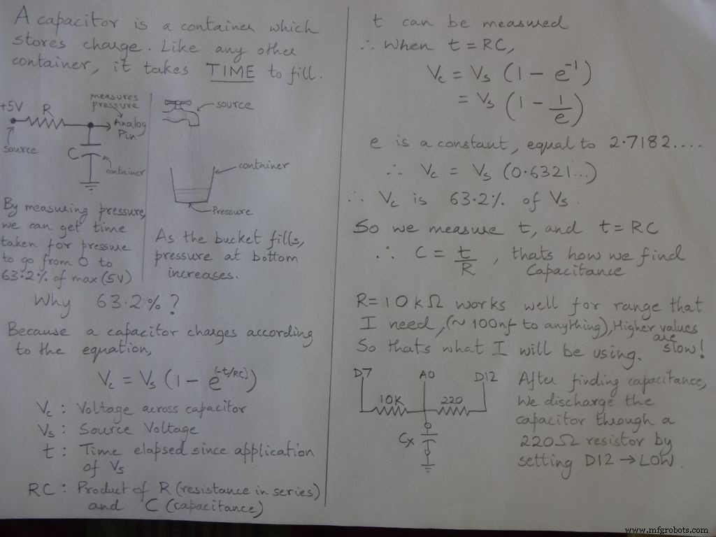
ステップ3:静電容量計-コンセプト <図>
 <図>
<図> 
コード
/ * RCTiming_capacitance_meter * Paul Badger2008から取得したコードの概念**ある時定数でのコンデンサの電圧は、充電電圧の63.2%として定義されます。 *つまり、コンデンサは1つの時定数で総容量の63.2%まで満たされます* / int analogPin =0; //コンデンサ電圧を測定するためのアナログピンintchargePin =7; //コンデンサを充電するためのピン-充電抵抗の一端に接続されていますintchargePin =12; //コンデンサを放電するためのピン。ダイオードテスト(chechPin1)に使用されるものと同じです。floatresistorValue=10000.0; // 10kOhm抵抗unsignedlongstartTimeを使用します; unsigned longlapsedTime;フロートマイクロファラッド; //精度を維持するための浮動小数点変数、計算をfloat nanoFarads; void setup(){pinMode(chargePin、OUTPUT); // ChargePinを出力に設定しますdigitalWrite(chargePin、LOW); Serial.begin(9600); //デバッグ用にシリアル送信を初期化します} void loop(){digitalWrite(chargePin、HIGH); // ChargePinをHIGHに設定し、コンデンサの充電を開始しますstartTime =millis(); while(analogRead(analogPin)<648){// 647は1023の63.2%であり、これはフルスケール電圧に対応します} lapsedTime =millis()-startTime; //ミリ秒を秒(10 ^ -3)に変換し、ファラッドをmicroFarads(10 ^ 6)に変換し、net 10 ^ 3(1000)microFarads =((float)elapsedTime / resistanceValue)* 1000; //(float)「unsignedlong」経過時間をfloat Serial.print(elapsedTime);に変換します。 //値をシリアルポートに出力しますSerial.print( "mS"); //単位を出力if(microFarads> 1){Serial.print((long)microFarads); //値をシリアルポートに出力しますSerial.println( "microFarads"); //単位を出力} else {//値が1マイクロファラッドよりも小さい場合は、nanoFarads(10 ^ -9ファラッド)に変換します。 nanoFarads =microFarads * 1000.0; // 1000を掛けて、nanoFarads(10 ^ -9ファラッド)に変換しますSerial.print((long)nanoFarads); //値をシリアルポートに出力しますSerial.println( "nanoFarads"); //印刷単位} / *コンデンサを放電します* / digitalWrite(chargePin、LOW); //充電ピンをLOWに設定pinMode(chargePin、OUTPUT); //放電ピンを出力に設定しますdigitalWrite(chargePin、LOW); //放電ピンをLOWに設定while(analogRead(analogPin)> 0){//コンデンサが完全に放電されるまで待機} pinMode(chargePin、INPUT); //放電ピンを入力に戻します}
ステップ4:ダイオードテスト <図>
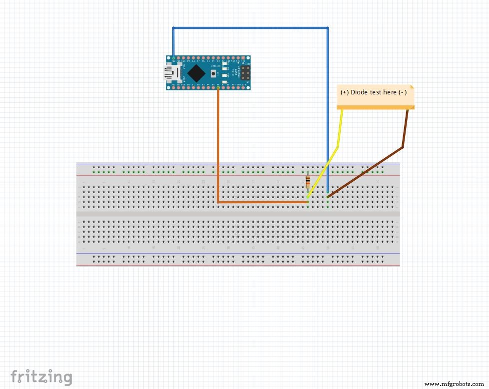
アナログピンは、10kオームの抵抗で5Vにプルアップされます。したがって、アナログピンは 1023 を読み取ります 何も接続されていないとき。 D12 OUTPUT に設定されています 、低 。
ダイオードがアナログピン間で順方向にバイアスされている場合 ( 5V )および D12 ( GND )、アナログピン 100-400 を読み取ります 。
逆バイアスをかけると、実際には非常に小さな電流が流れ、アナログピン 900-1023 を読み取ります 。
このようにして、任意のダイオードのp側とn側を簡単に見つけることができます。これは、LEDとダイオードをすばやくチェックするために使用できます。
コード
String state ="null"; int checkPin1 =12; int checkPin2 =6; void setup(){Serial.begin(9600);} void loop(){pinMode(checkPin1、OUTPUT); digitalWrite(checkPin1、LOW); //ピン11はローに設定されます//アナログ読み取りは通常10k抵抗によってプルアップされるため、ヌル読み取りは1023 //フォワードバイアスでは、アナログピンはLOWであるcheckPin1に接続されます。したがって、読み取り値が1023 //未満の場合、逆バイアスでも実際には小さな電流が流れるため、700を使用してif(analogRead(checkPin2)<700){state ="forward";を区別します。 } Serial.println(state); Serial.println(analogRead(checkPin2)); state ="null"; delay(500);}
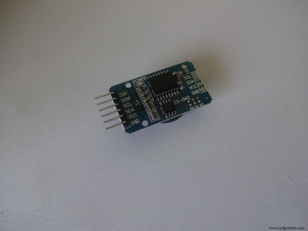
ステップ5:リアルタイムクロック(RTC) <図>
 <図>
<図> 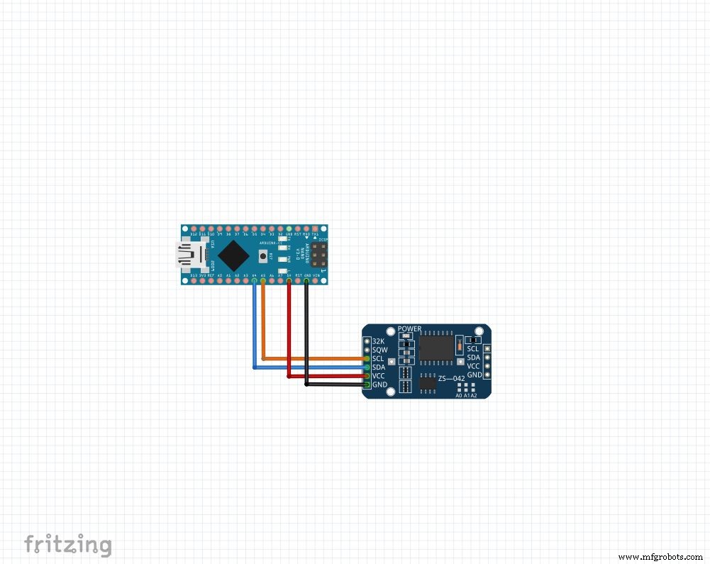
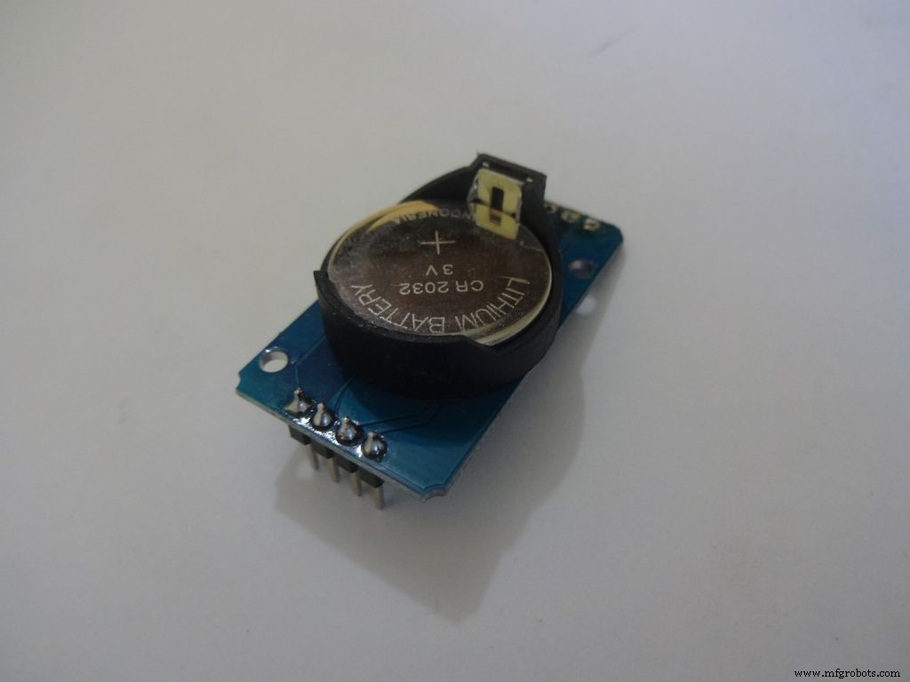
RTCは、秒、分、時間、日、日付、月、および年の情報を保持します。小さなコイン電池のおかげで外部電源を切ってもカウントを続けます。うるう年の修正を含め、31日未満の月については、月末の日付が自動的に調整されます。
どのモジュールを使用する場合でも、4つのピンを使用します: Vcc 、 GND 、 SDAおよびSCL 。 SDA および SCL arduinonanoとunoのピンは A4 および A5 それぞれ。他のarduinoについては、グーグルで検索してください!
時間の設定とアクセスが非常に簡単な「RTClib」ライブラリを使用します。ライブラリはここからダウンロードできます([ZIPのダウンロード]をクリックして、Arduinoライブラリフォルダーにある「RTClib-master」を抽出します。ライブラリのインストールの詳細)
時間を設定するには、このステップに添付されている「RTC_set_time.ino」をダウンロードして、行のコメントを解除します。
rtc.adjust(DateTime(F(__ DATE __)、F(__ TIME__)));
コンパイル中にコンピュータに設定された時間を使用したい場合。または
rtc.adjust(DateTime(2014、1、21、3、0、0)); //年、月、日付、時、分、秒
カスタム時間を設定します。
図のように接続してアップロードします。 シリアルを開く 9600ボーで監視する 現在の時刻を確認します。数時間後にもう一度チェックして、RTCがどのように追いついているかを確認してください。
必ずこれらの行を推奨し、時間を一度設定した後で再度アップロードしてください。そうしないと、Arduinoがリセットされるたびにリセットし続けます!
コード
// I2CとWireを介して接続されたDS1307RTCを使用した日付と時刻の関数lib#include #include RTC_DS1307 rtc; // RTC_DS1307の「rtc」オブジェクトの作成、オブジェクト関数にアクセスするために使用されます//オブジェクトとクラスの詳細:https://www.youtube.com/watch?v =ABRP_5RYhqUchar daysOfTheWeek [7] [12] ={"Sunday"、 "Monday"、 "Tuesday"、 "水曜日 "、"木曜日 "、"金曜日 "、"土曜日 "}; void setup(){Serial.begin(9600); rtc.begin(); //次の行は、RTCをこのスケッチがコンパイルされた日時に設定します// rtc.adjust(DateTime(F(__ DATE __)、F(__ TIME__))); //この行は、明示的な日付と時刻を使用してRTCを設定します。たとえば、// 2014年1月21日午前3時に、次のように設定します。//rtc.adjust(DateTime(2014、1、21、3、0、0) );} void loop(){DateTime now =rtc.now(); Serial.print(now.year()); Serial.print( '/'); Serial.print(now.month()); Serial.print( '/'); Serial.print(now.day()); Serial.print( "("); Serial.print(daysOfTheWeek [now.dayOfTheWeek()]); Serial.print( ")"); Serial.print(now.hour()); Serial.print( ':'); Serial.print(now.minute()); Serial.print( ':'); Serial.print(now.second()); Serial.println(); Serial.println(); delay(1000);}
ステップ6:最終設定 <図>
 <図>
<図> 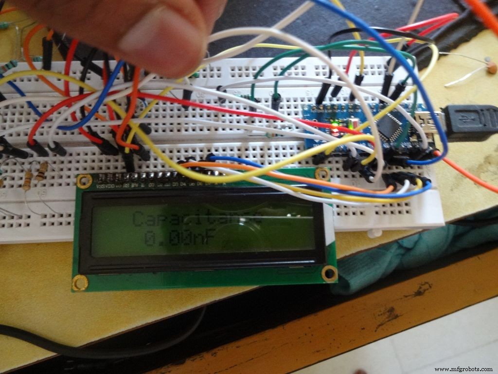
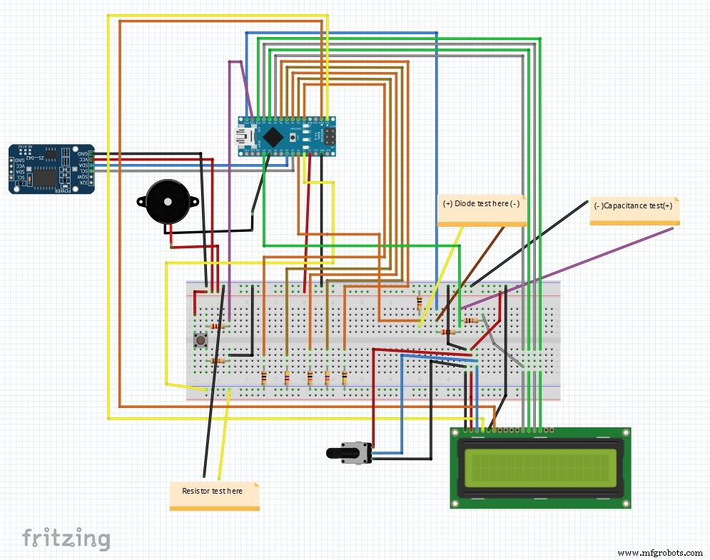
これが、すべての要素を組み合わせた後の最終回路です。メインコードとフリッツファイルは最後に添付されています。
まだダウンロードしていない場合は、fritzing.orgからfritzingをダウンロードしてください。
Main_code.rarファイルを抽出し、Main_file_rtc.inoを開きます。すべての変数宣言を個別の definations.h に含めました。 ヘッダーファイル。メインコードを開くと自動的に追加されます。
さまざまな部分が関数になります: Clock() 、 findResistance() 、 findCapcitance() および diodeTest() 。これらは別々のタブに書かれているため、読みやすく、変更も簡単に実装できます。メインファイルは「モードボタン」の状態をチェックし、適切な関数を呼び出します。
その他の詳細は、コード自体で適切に説明されています。
ブレッドボードでテストを実行した後、ICの作成を開始する準備が整いました!
注:ブザーは、まだ使用されていない場合は、必要に応じて使用できます。たとえば、連続機能などです。
ステップ7:スイッチの準備 <図>
 <図>
<図> 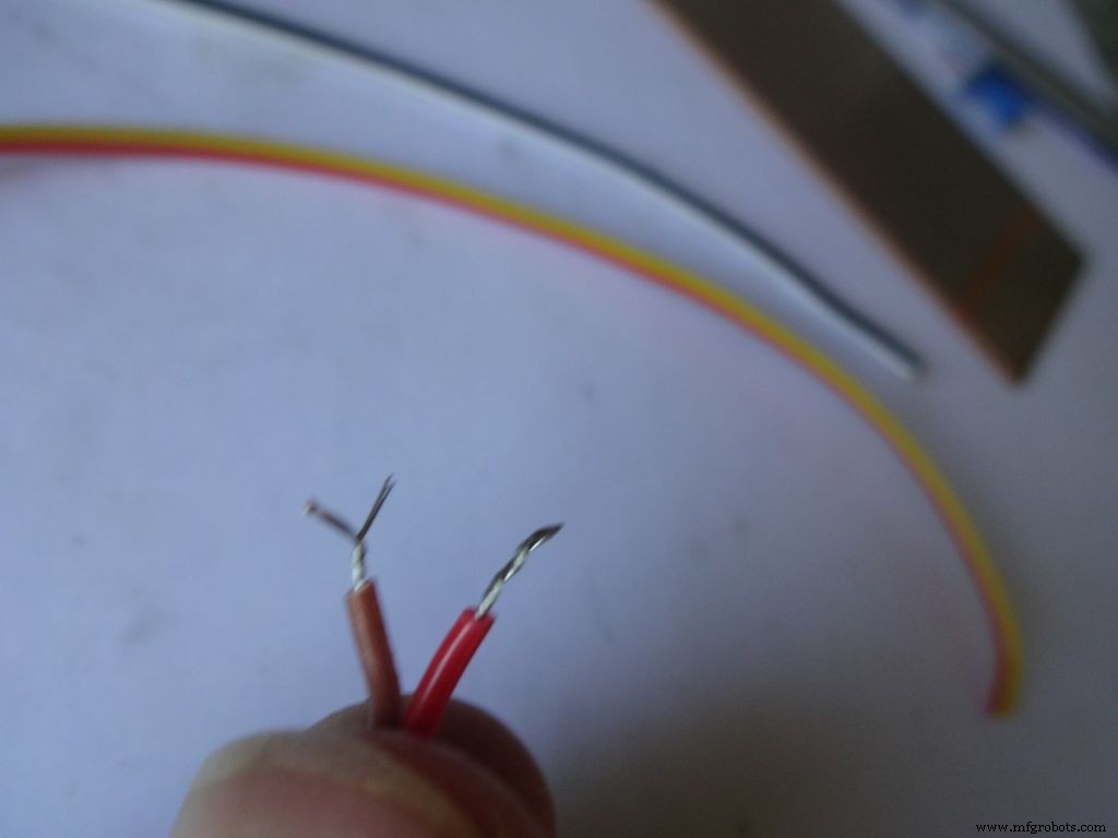 <図>
<図> 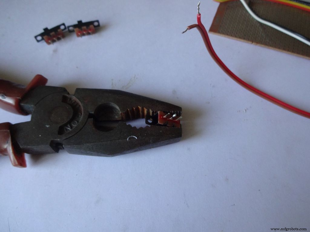 <図>
<図> 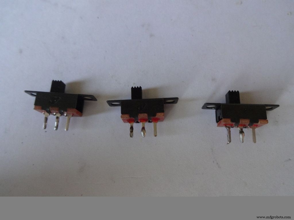 <図>
<図> 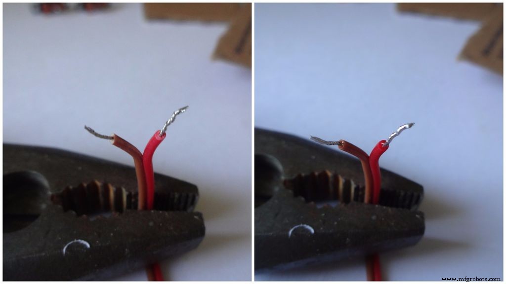 <図>
<図>  <図>
<図> 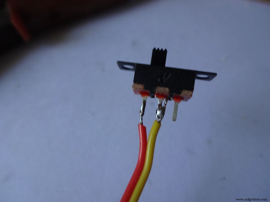 <図>
<図> 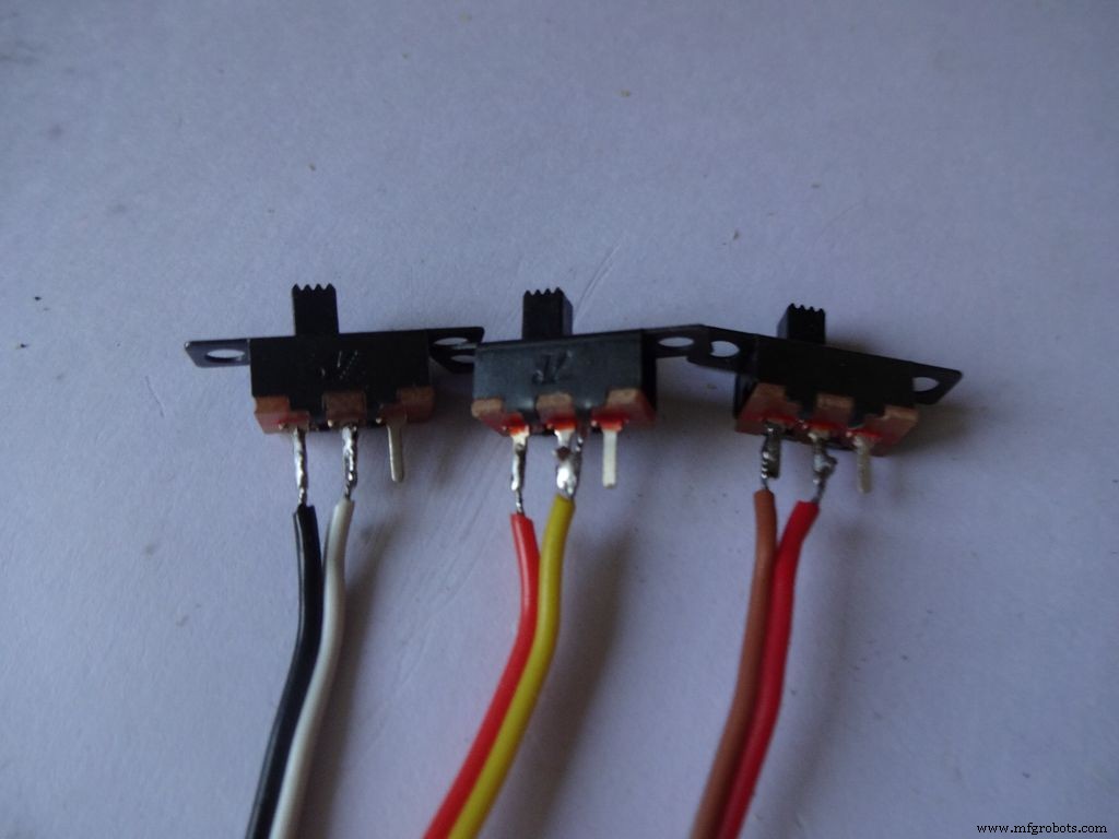 <図>
<図> 
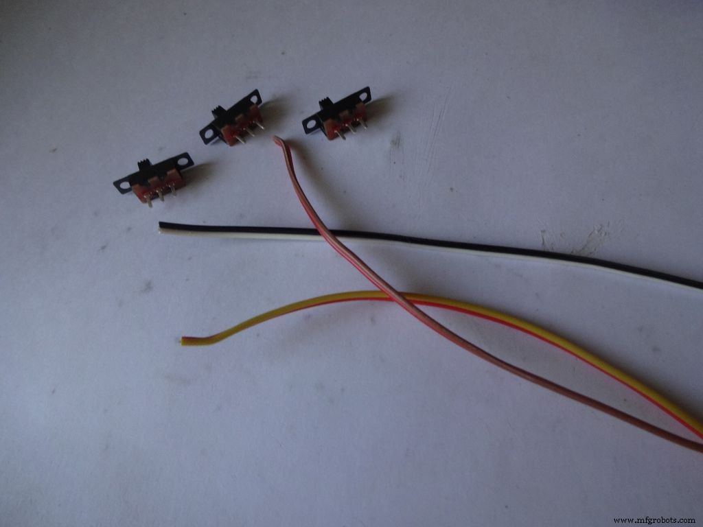
3つのスライドスイッチと3対のワイヤー(長さ約10cm)を用意します。このためにリボンケーブルを分割しました。
断熱材のごく一部(5mm以下)を剥がし、ストランドをねじります。
各スイッチの隣接する2つのピンにはんだを塗布します。何かを使ってそれを保持しますはんだ付けする間、私は重いペンチを使用しました。
以前にはんだ付けしたことがない場合は、今が開始するのに良い時期です。 Youtubeには、適切にはんだ付けする方法を説明するビデオがたくさんあります。 PACEからのレッスンは非常に有益です、それを見てください。
次に、ワイヤーを「錫メッキ」する必要があります。はんだごての先端を錫メッキするワイヤーに接触させます。チップとワイヤーの間に少量のはんだを塗布します。これにより、チップからワイヤーに熱を伝導するブリッジが作成されます。次に、はんだごての先端の反対側で、ワイヤーに直接はんだを適用します 。はんだを取り除きます。チップを取り外します。これに関するビデオ。
その後、スイッチを所定の位置に保持し、錫メッキされたワイヤーの1つをピンに持ってきて、はんだごてに触れてはんだをリフローします。 2番目のワイヤーでも同じようにします。スイッチの片側に濃い色のワイヤーを配置していることに注意してください。
ここで手順を繰り返し、2本のワイヤーを押しボタンに取り付けます(これによりリセットボタンになります)。 通常接続されているボタンの端にワイヤーを接続しないように注意してください。
ステップ8:ケースを作成する-レイアウトをカットする <図>
 <図>
<図> 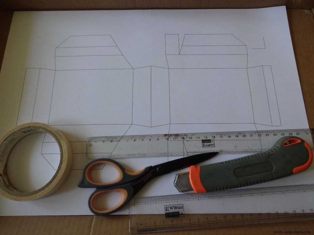 <図>
<図> 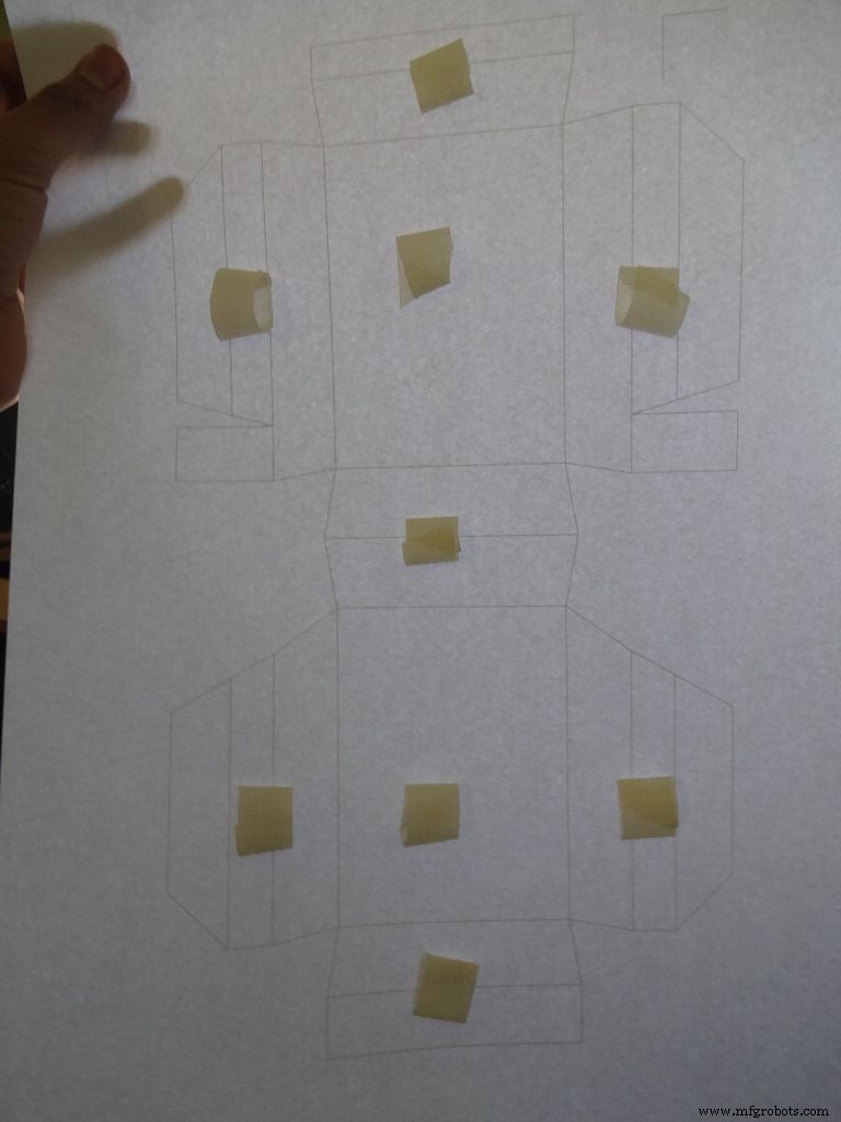 <図>
<図> 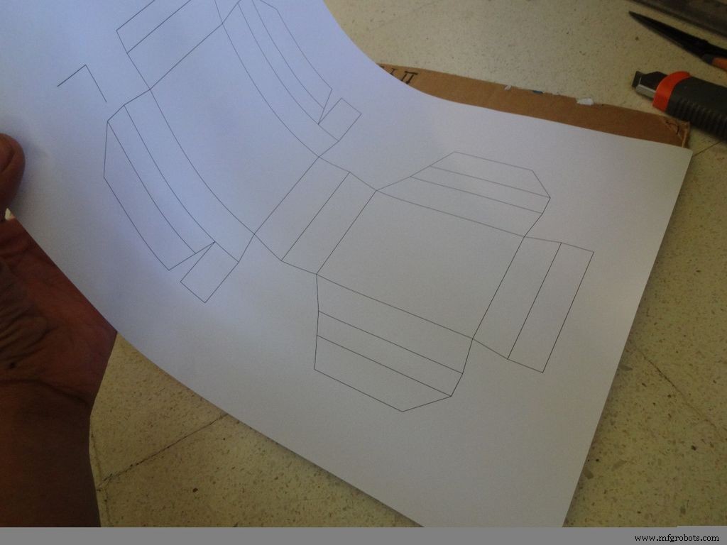 <図>
<図> 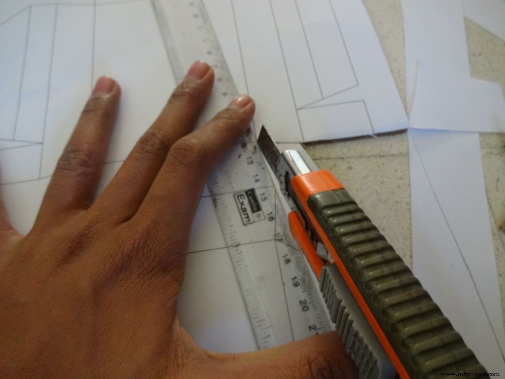 <図>
<図> 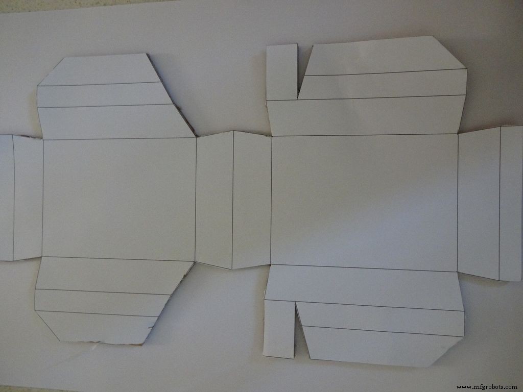
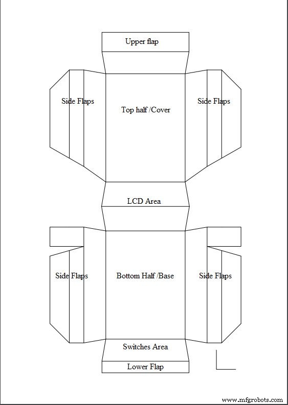
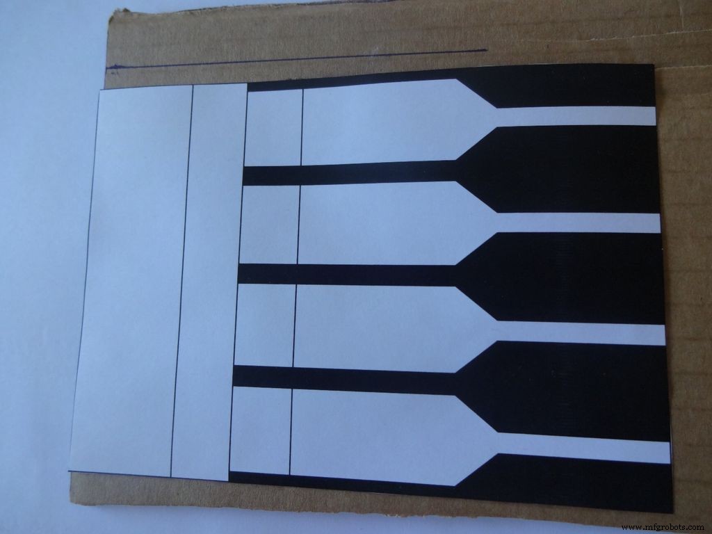
お住まいの地域で利用可能な用紙サイズに基づいて、「Layout_Final_A3.pdf」または「Layout_Final_ANSI_B.pdf」をダウンロードしてください。最後に添付されています。
A3サイズの用紙(29.7 x42.0cmまたは11.69x 16.53インチ)または米国の代替ANSI B(11 x17インチまたは279x 432mm)に印刷します。 印刷中に適切な用紙サイズと向きを選択し、[実際のサイズ]オプションを選択していることを確認してください。 右下隅の小さな直角を測定して、印刷が正確であることを確認します。2cmx2cmである必要があります。
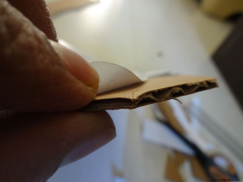
段ボールをレイアウトよりも大まかに切り取ります。テープの小片を引き裂き、「両面粘着性」ロールを形成し、示されている場所に貼り付けます。次に、シートを段ボールに貼り付けます。
鋭利なはさみまたは定規付きのカッターナイフを使用して、ケースレイアウトの外側の境界を切り取ります。はさみよりもカッターナイフの方がはるかに優れていることがわかりました。ほとんどのカッターには、新鮮で鋭い先端を得るために段階的に壊すことができるブレードがあるので、そうすることをお勧めします。カットする部分の下に別の段ボールまたは木を置きます。これは、よりきれいなカットを得るのに役立ちます。
また、切断中に定規をライン上に適切に保持しないことは、一般的なエラーです。急いでこれをしないでください。
ステップ9:ケースの作成-折り目と折り畳み <図>
 <図> <図>
 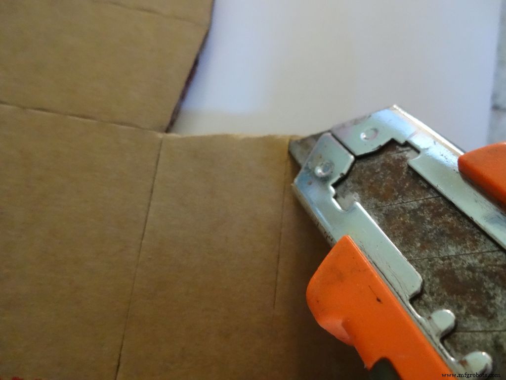 <図>
<図> 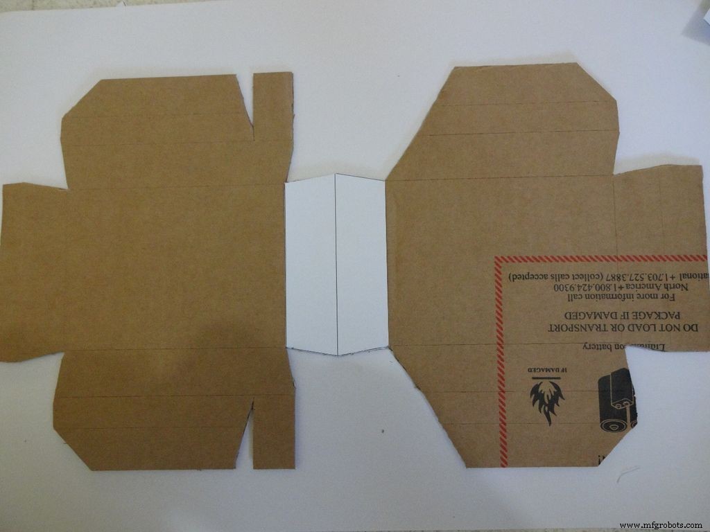 <図>
<図> 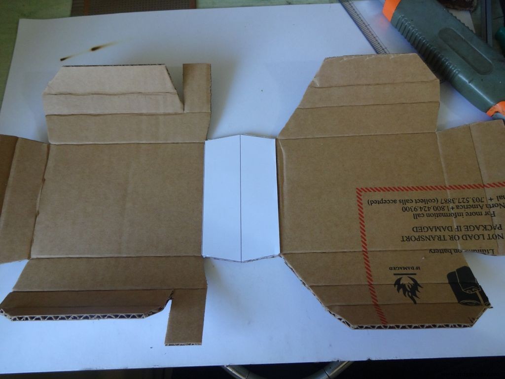 <図>
<図> 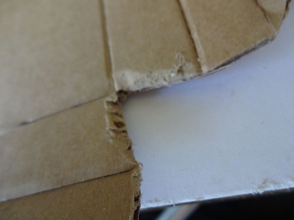 <図>
<図> 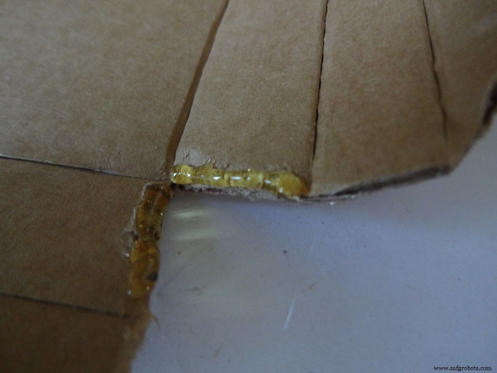 <図>
<図>  <図>
<図> 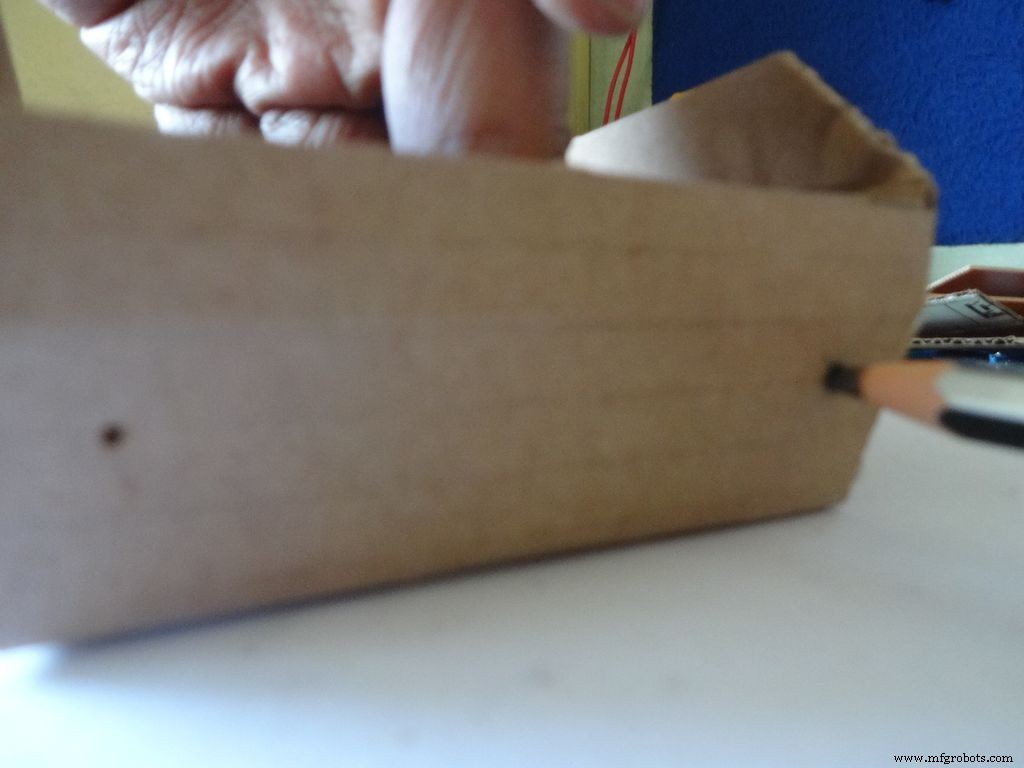 <図>
<図> 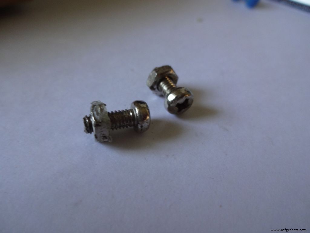 <図>
<図> 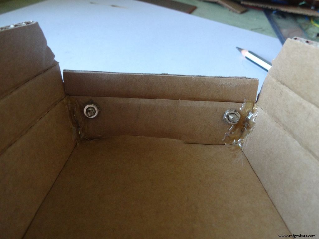 <図>
<図> 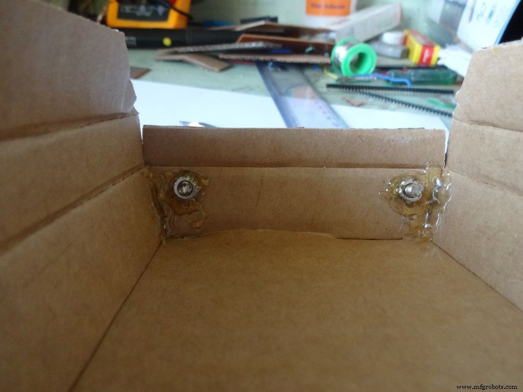 <図>
<図>  <図>
<図> 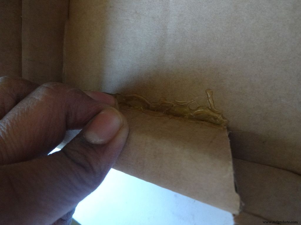 <図>
<図> 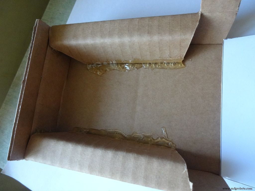
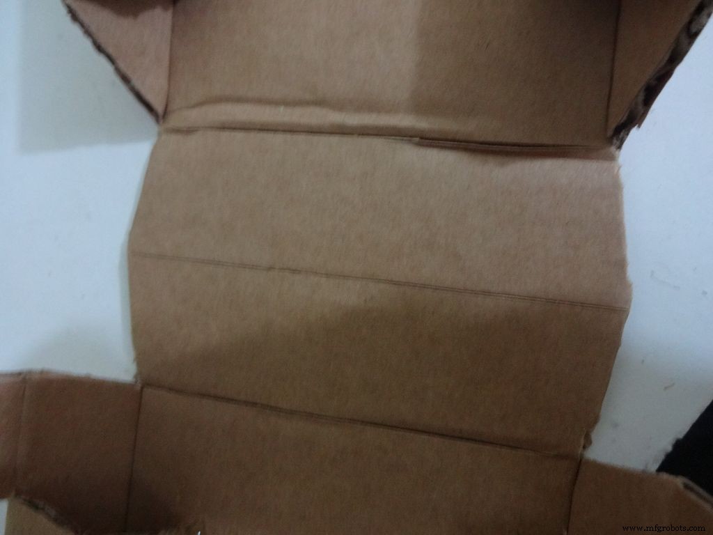
目盛り付きのカッターを使用して、LCD領域の中央の線を除くすべての折り線に沿って慎重に折り目を付けます。 すべての折り畳み可能な部品を曲げて折り畳み、不完全な折り目を修正します。
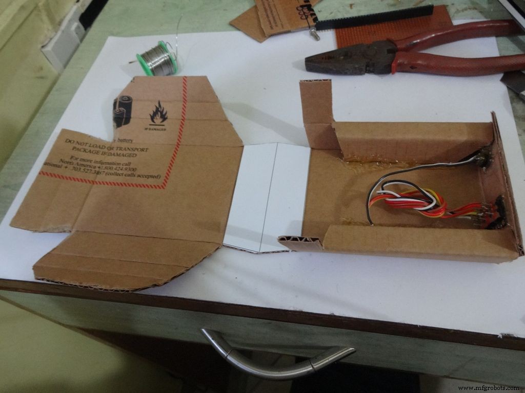
下半分またはベースの場合:
サンドペーパーサンドを使用して、最初の4つのエッジを傾斜させ、接着剤ガンでホットグルーを塗布し(一度に片側)、接着剤が冷えるまで30〜60秒間結合して保持します。
図のようにサムピンで2つの穴を開け、ボルトがはまるのに十分なだけ鉛筆で拡大します。内側のナットを締め、ホットグルーを塗布し(ナットにちょうど!)、冷まします。スクドライバーでボルトを外します。
次に、2つのサイドフラップを内側に折り、貼り付けます。フラップの外側部分は少し傾けて、中央部分は平らにする必要があります。
ステップ10:ケースを作成する-スイッチを追加する <図>
 <図>
<図> 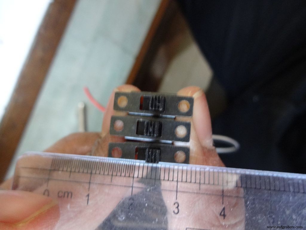 <図>
<図> 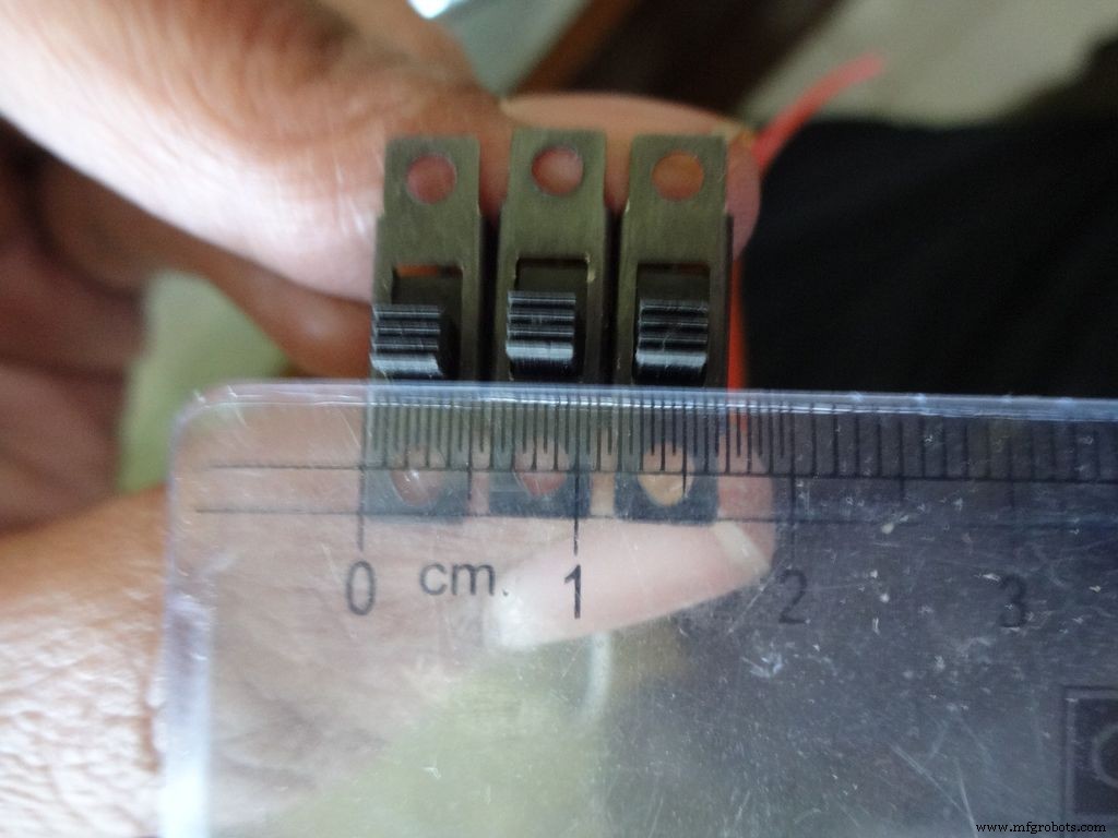 <図>
<図> 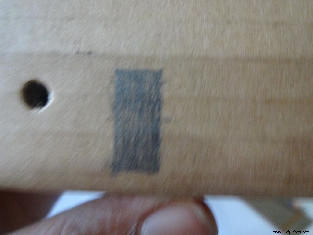 <図>
<図> 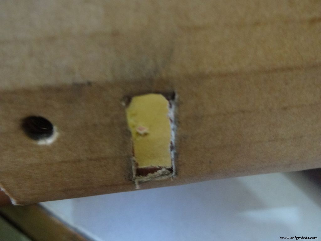 <図>
<図> 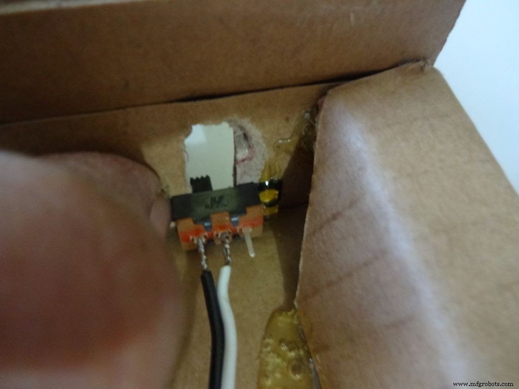 <図>
<図> 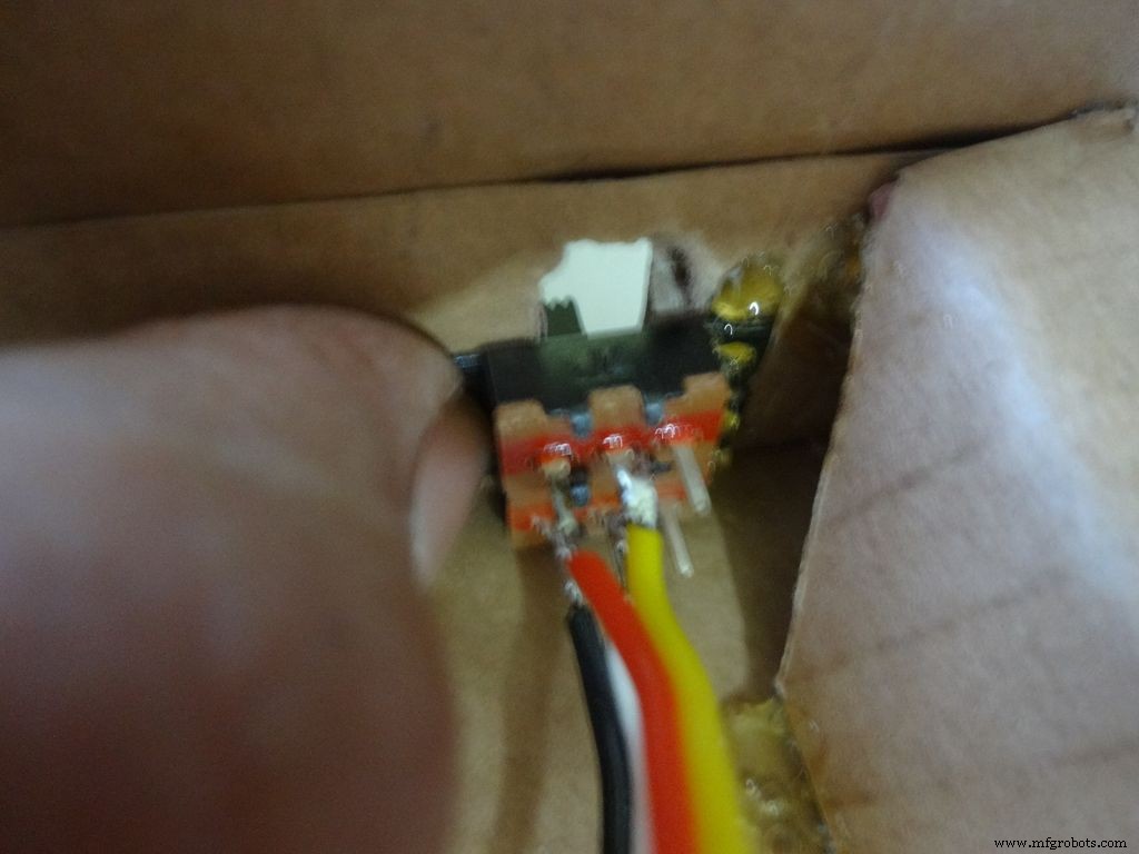 <図>
<図> 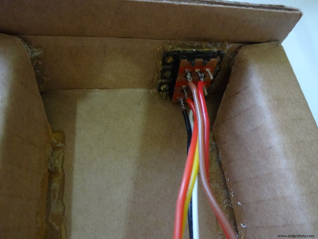 <図>
<図> 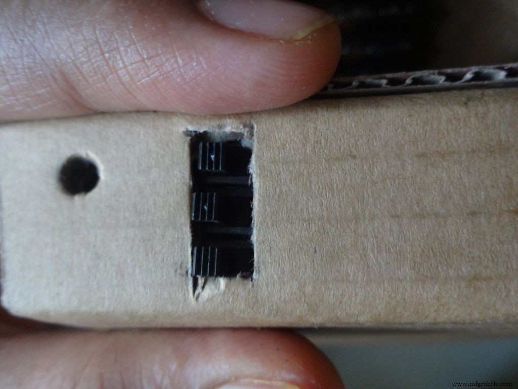 <図>
<図> 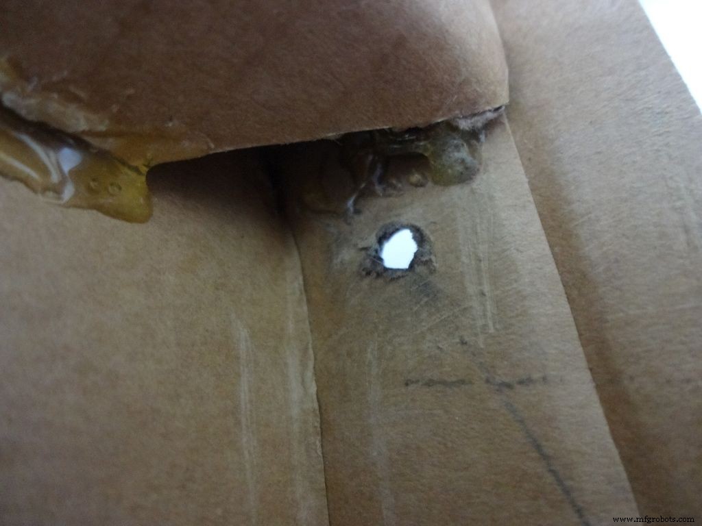 <図>
<図> 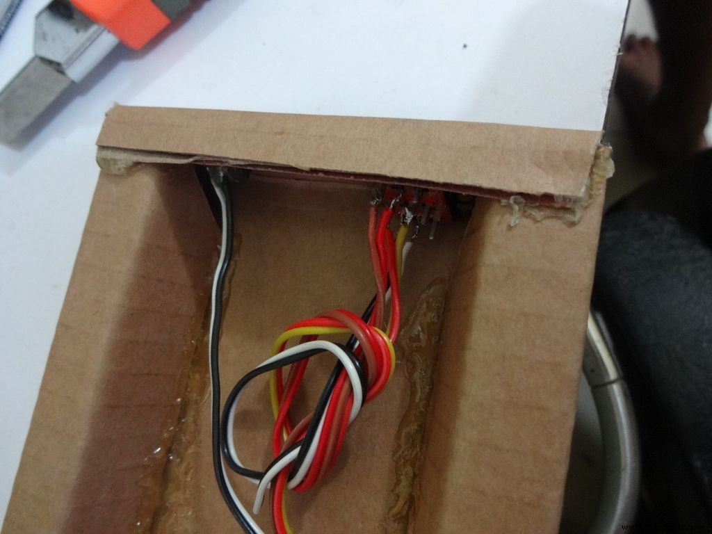 <図>
<図> 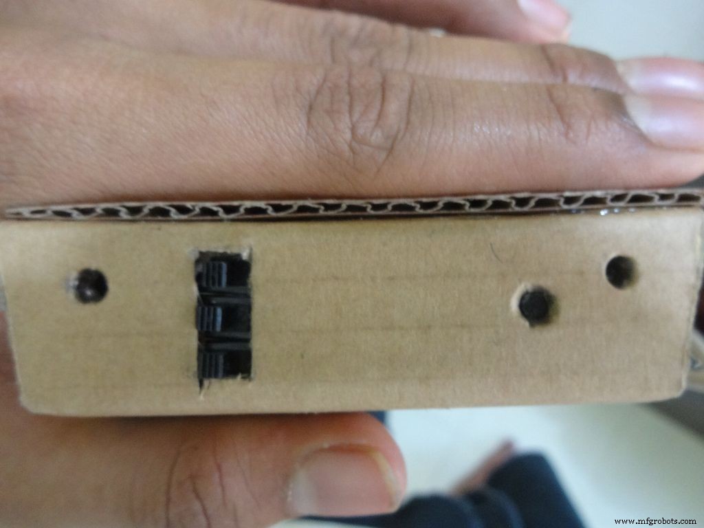 <図>
<図> 
前にはんだ付けしたワイヤーで3つのスライドスイッチを取り、必要な長方形のおおよその寸法を測定します。ボックスの左側(外側から左)にマークを付けます。カッターでカットし、内側を少しサンドして、はみ出しているものを取り除きます。
最初のスイッチを所定の位置に保持し、それを保持しながら片側に接着剤を追加します。冷ましてください。他の2つでも繰り返し、残りの面に接着剤を追加します。注:スイッチの配線ピンは同じ側にある必要があります。
リセット押しボタン用に反対側に別の穴を開けます。ボタンを所定の位置に保持し、接着剤を追加します。下のフラップを内側に折り、貼り付けます。
ステップ11:ケースの作成-上半分またはカバー <図>
 <図>
<図> 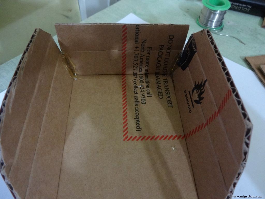 <図>
<図> 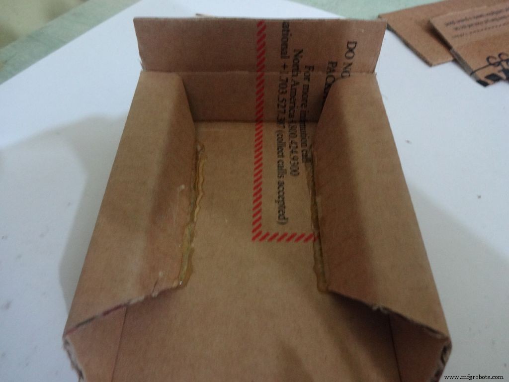 <図>
<図> 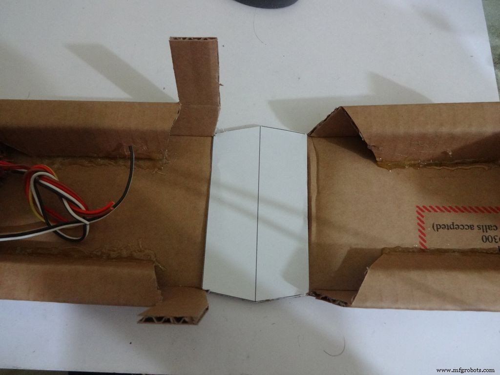
上半分のエッジをサンドし、サイドフラップを内側に(ベースと同じように)貼り付けます
ステップ12:ケースを作成する-LCDを追加する <図>
 <図>
<図> 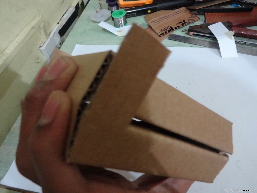 <図>
<図> 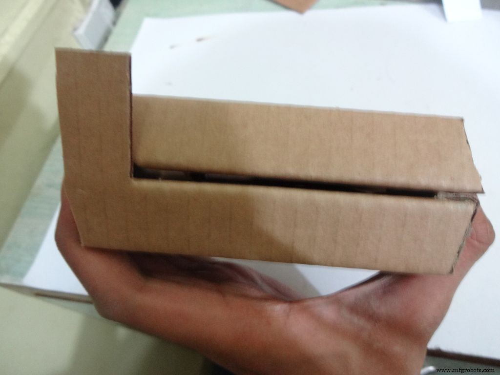 <図>
<図>  <図>
<図>  <図>
<図>  <図>
<図>  <図>
<図> 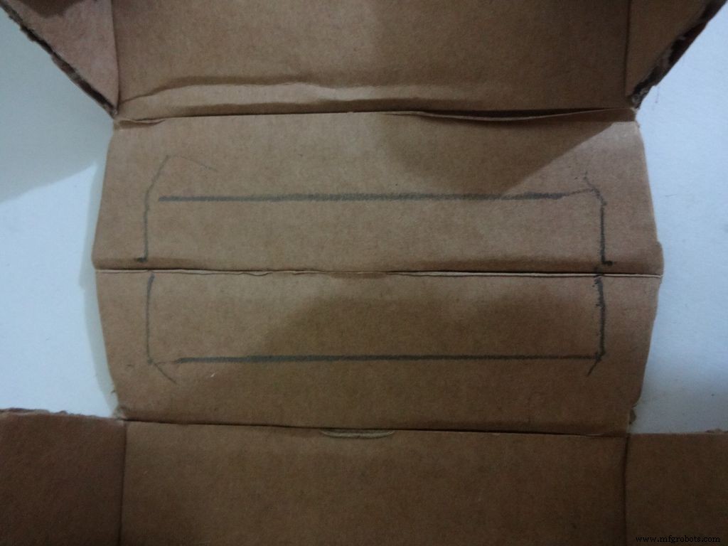 <図>
<図> 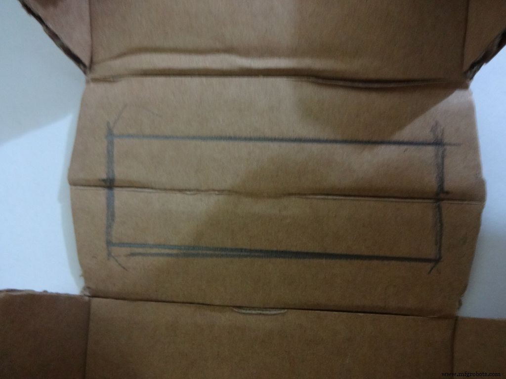 <図>
<図> 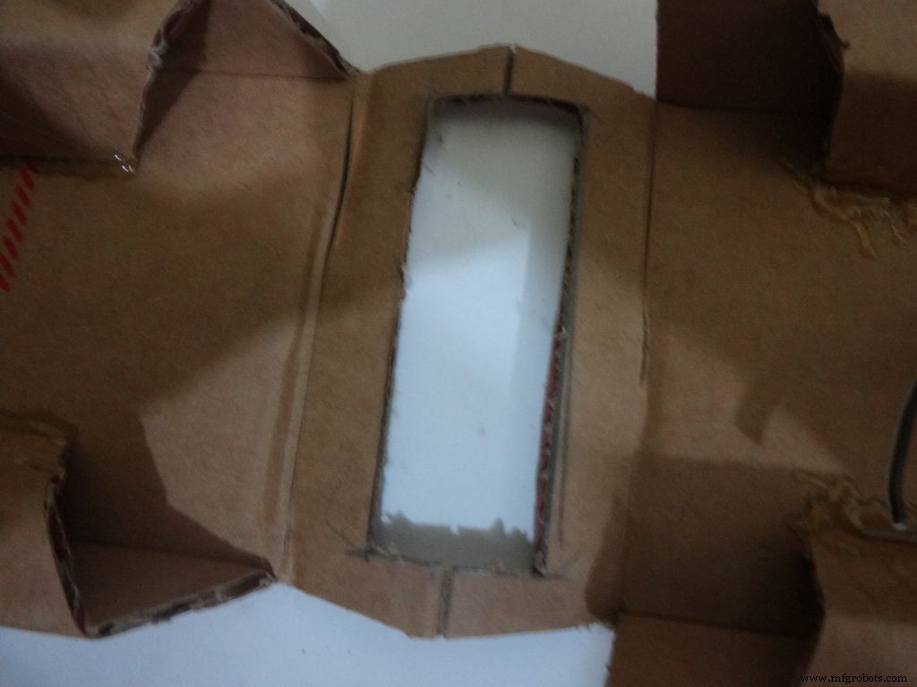 <図>
<図> 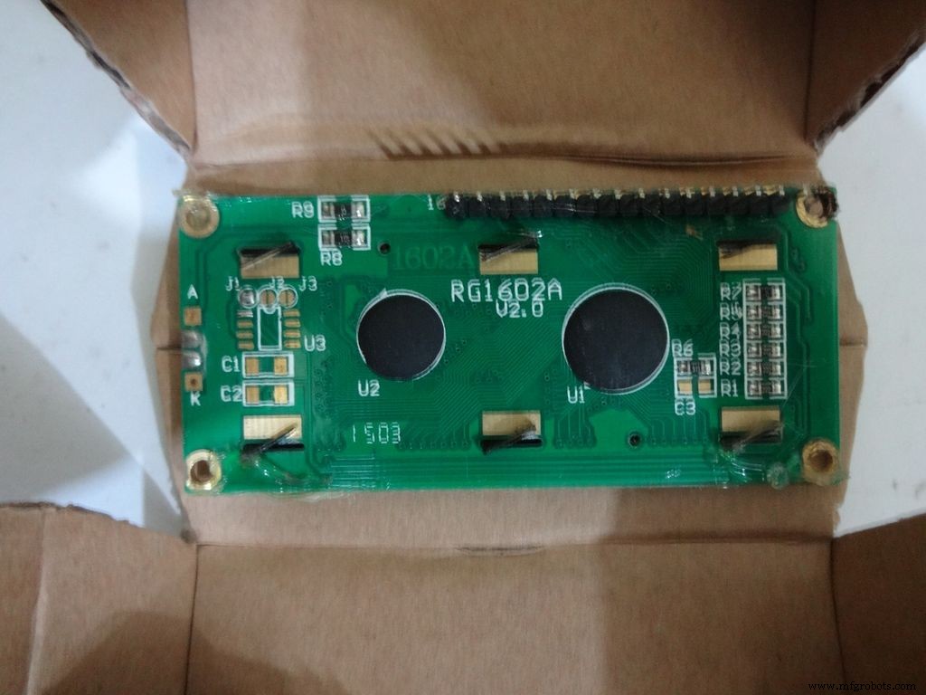 <図>
<図> 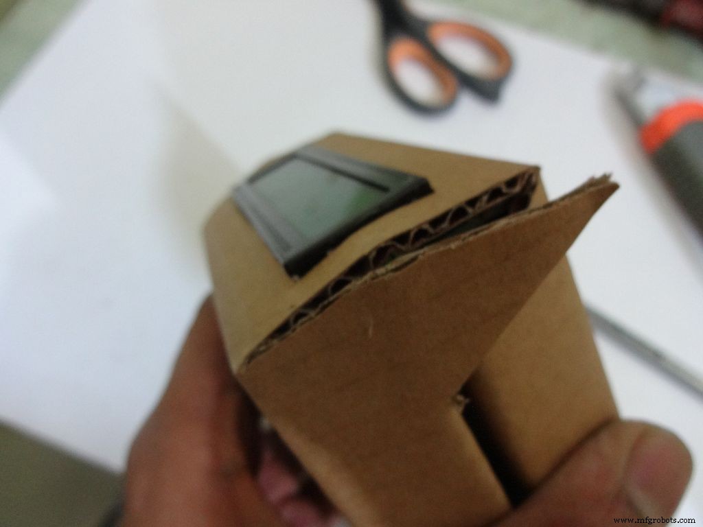 <図>
<図> 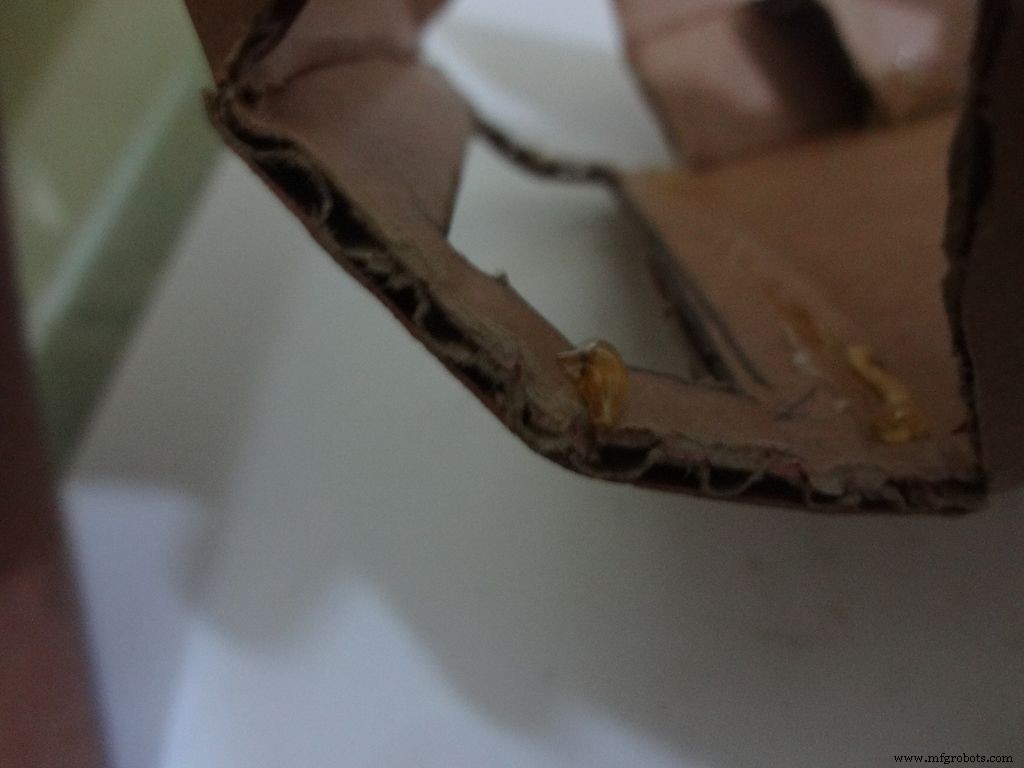 <図>
<図> 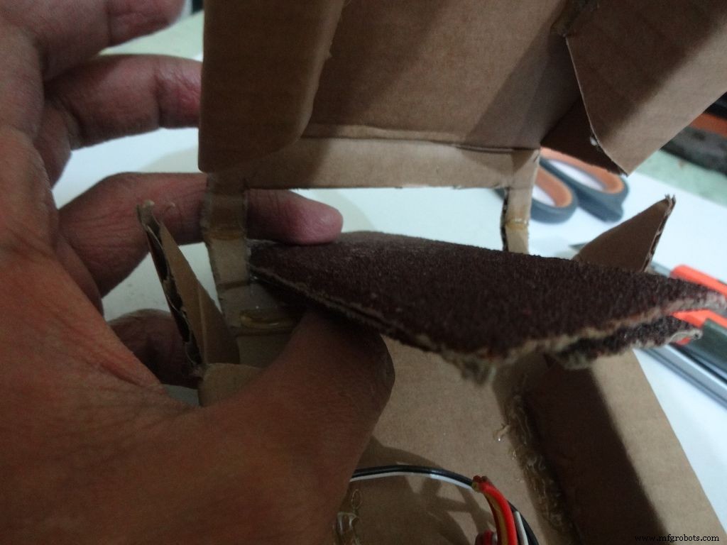 <図>
<図> 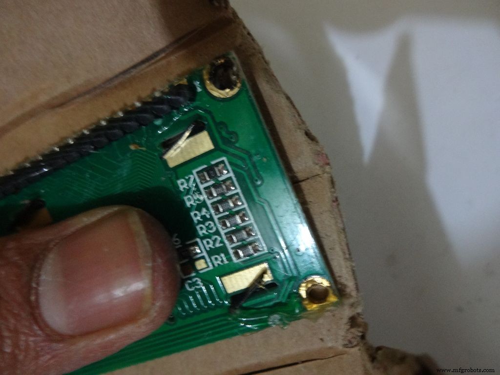 <図>
<図> 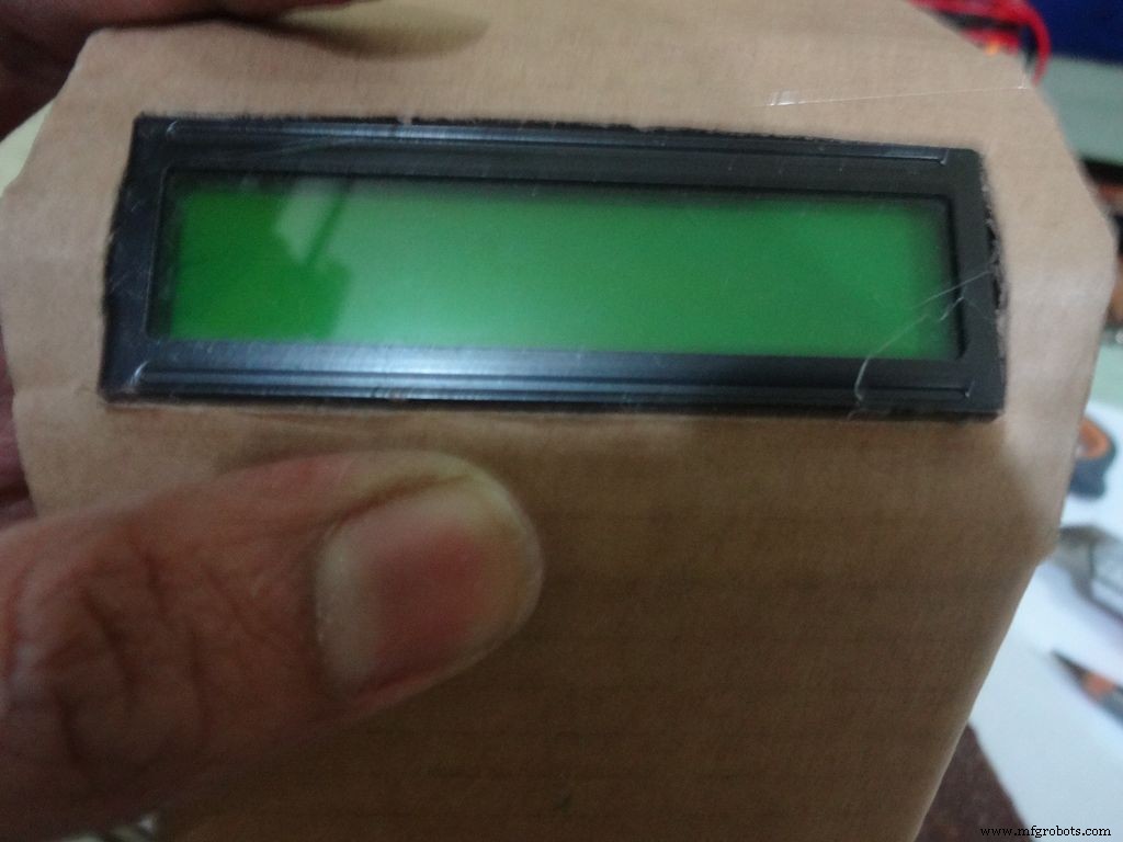
真ん中の線に折り目を付けます。 (デリケートですぐに緩むので、早めにやらなかった)
カバーをベースまで折りたたんで、すべてが正常に見えるかどうかを確認します。ICピン用に十分な間隔を空ける必要があります。 (写真を参照)
画像のようにカバーフラップをカットします。
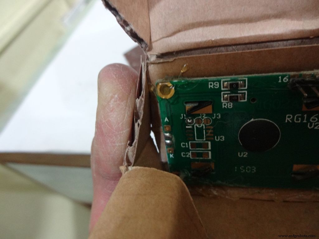
LCDをLCD領域の中央に置き、鉛筆で印を付けます。定規を使用して、長方形を適切に作成し、カッターを使用して慎重にカットします。 LCDウィンドウを折り、ヒンジに接着剤を塗布して、ヒンジを正しい位置に保ちます。 LCDを挿入し、必要に応じて変更を加えます。
最後に、LCDの四隅に接着剤を塗布し(余分に置かないでください)、所定の位置に配置します。
ステップ13:ケースの作成-ファイナルフラップ <図>
 <図>
<図> 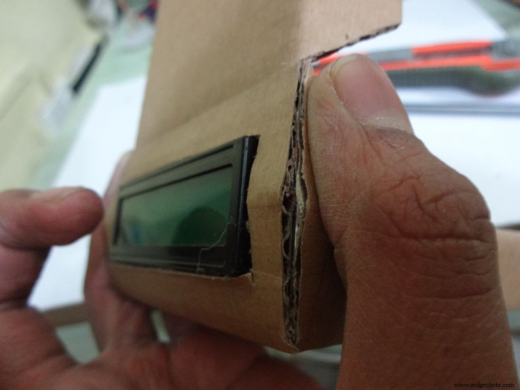 <図>
<図> 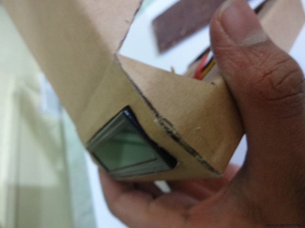 <図>
<図> 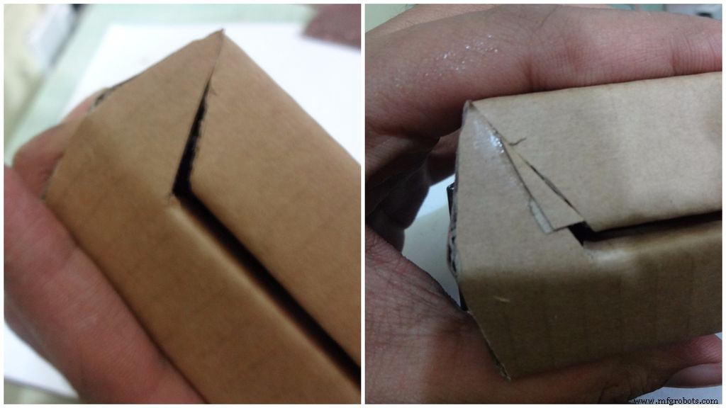 <図>
<図> 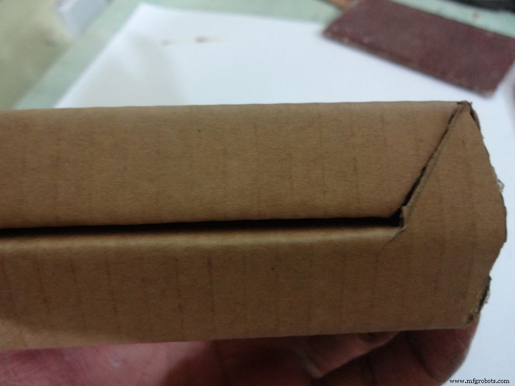 <図>
<図> 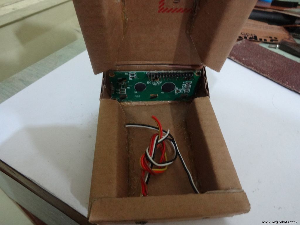 <図>
<図> 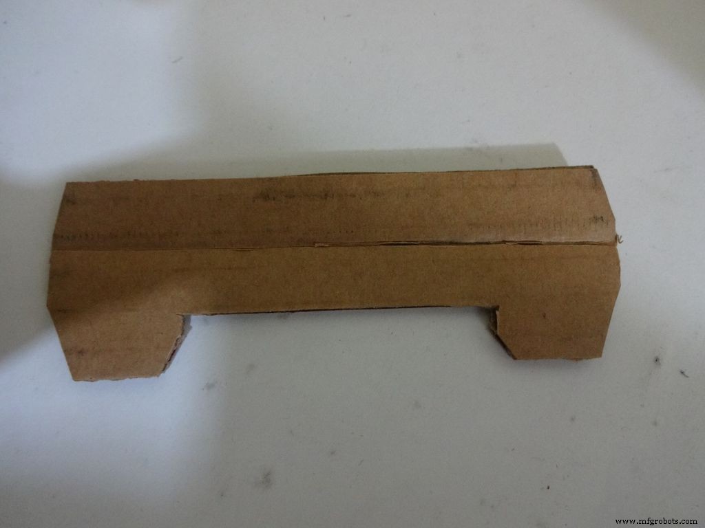 <図>
<図> 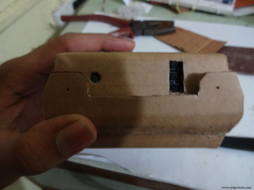
砂を入れ、トリミングして、環状フラップを閉じます。
図のように小片を作り、カバーに貼り付けます。 2つの穴を開け、鉛筆で広げてボルトを挿入し、カバーをベースにロックします。
ステップ14:回路基板-適合させる <図>
 <図>
<図> 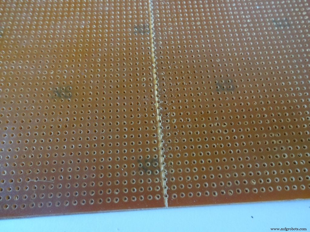 <図>
<図> 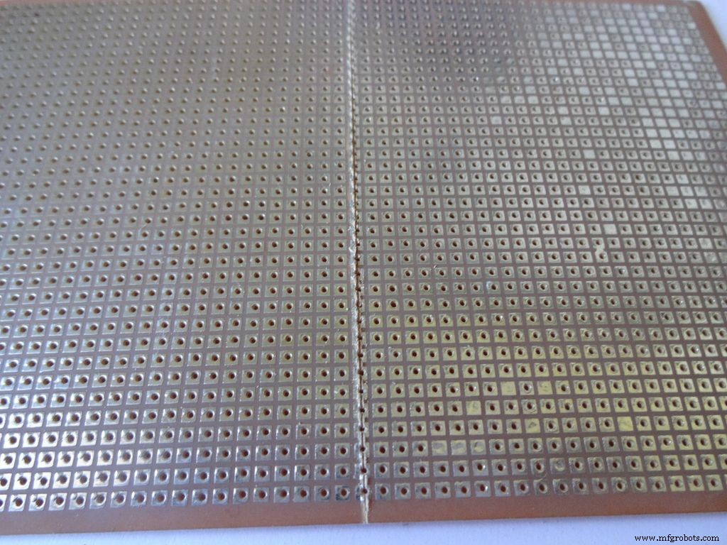 <図>
<図> 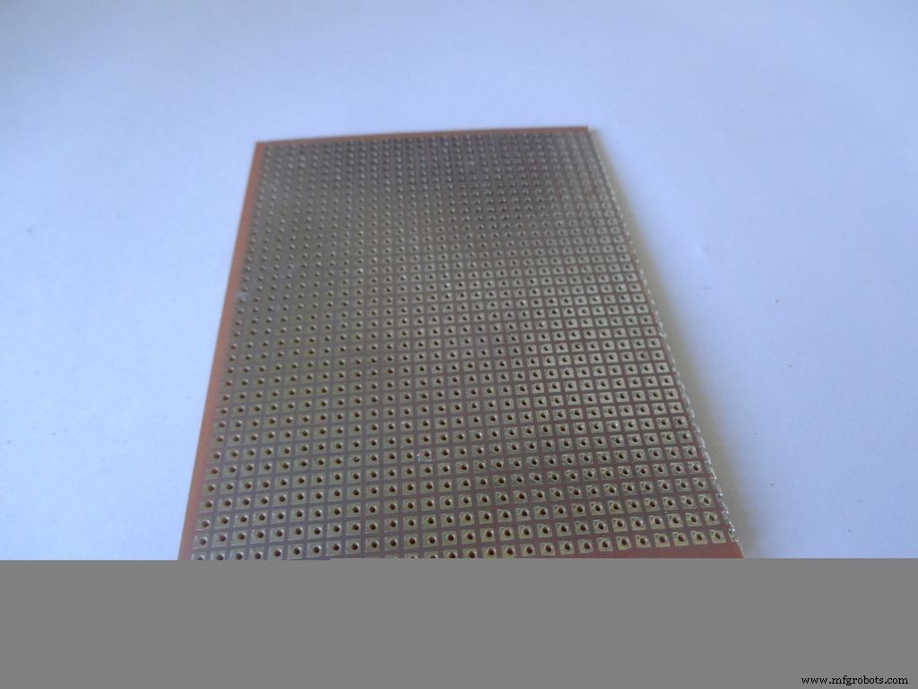 <図>
<図>  <図>
<図>  <図>
<図> 
汎用PCBを、ケースに適切に収まるように適切なサイズにカットします。鉱山は2x4インチです。カットするには、定規とカッターを使用して、両側を複数回スワイプすると、簡単に壊れます。
中に入れてください。サイドフラップからの接着剤がPCBを持ち上げる場合は、接着剤を再加熱して平らにするか、PCBのサイズを少し小さくします。
3つのスイッチが収まり、PCBが完全に内側になるように、小さな部品を切り取ります。
ステップ15:回路基板-Arduino Nano <図>
 <図>
<図>  <図> <図>
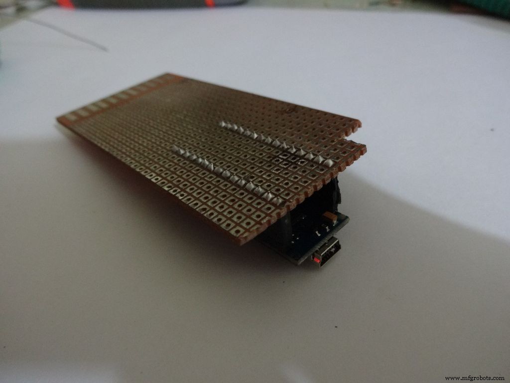
Arduinoに適したサイズのメスヘッダーピンをカットします。
PCBの中央の端に配置し、すべてのピンをはんだ付けします。
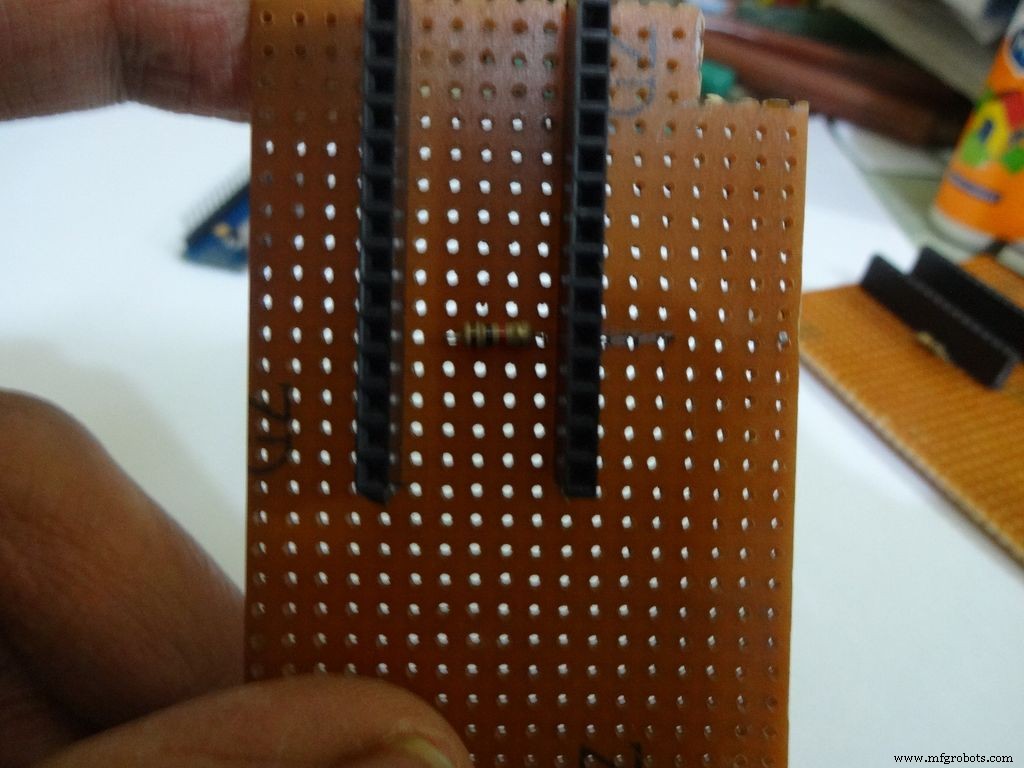
ステップ16:回路基板-抵抗計 <図>
 <図>
<図> 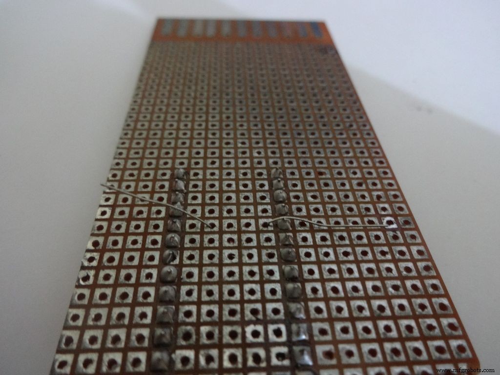 <図>
<図> 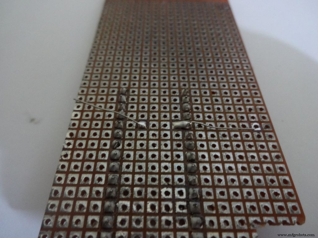 <図>
<図> 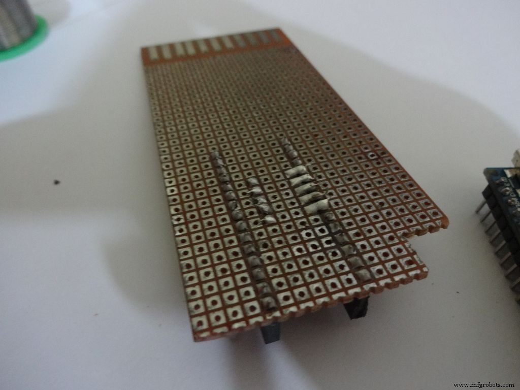 <図>
<図> 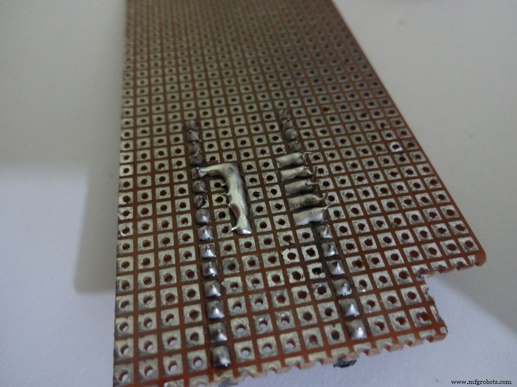
PCBに接続する前に、最終的な回路設計を再確認してください。
抵抗計の場合は、ピン D2 に1kオームの抵抗を追加することから始めます。 arduinoの。 arduinoを配置し、ピンに注意深くマークを付けます。裏側は、図のように曲げてはんだ付けします。
他の4つの抵抗、4.7k、10k、47k、100kオームでも同じようにします。
注:すべての許容範囲バンド(ゴールドバンド)を片側に保持することをお勧めします(例:UPとRIGHT)。
抵抗器の2番目の端を組み合わせて、 A7 にはんだ付けします。 。
ステップ17:回路基板-静電容量計とダイオードのテスト <図>
 <図>
<図> 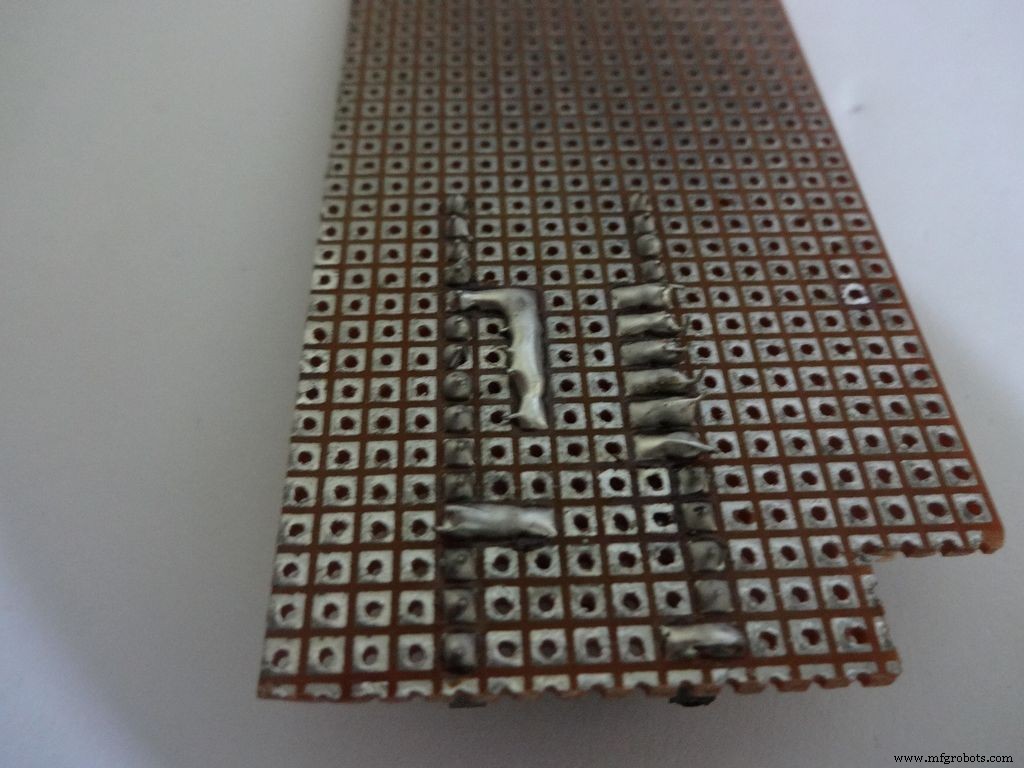 <図>
<図> 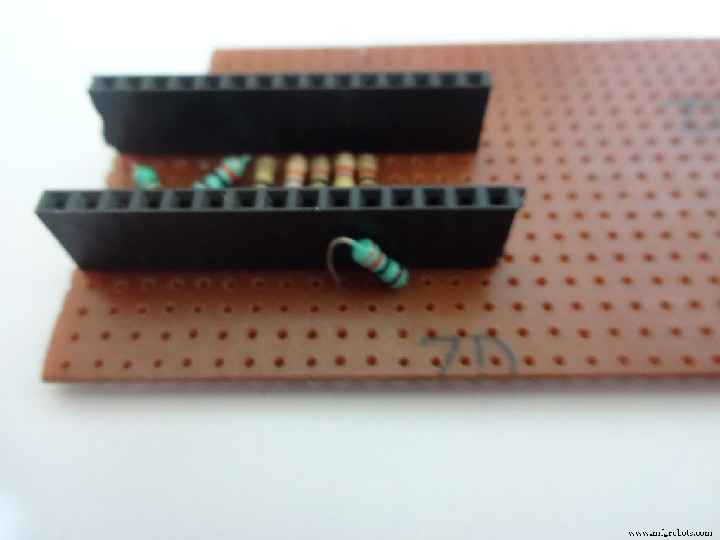
静電容量計:
D12 から220オームの抵抗器をはんだ付けします A0 へ 。そして、 A0 からの10kオームの抵抗器 D7 。
注: D7 (デジタルピン)はLCDデータピン D4 にも使用されます 。
ダイオードテスト:
A6 から10kオームのプルアップ抵抗をはんだ付けします + 5V 。
ステップ18:LCD用のコネクタを作成する <図>
 <図>
<図> 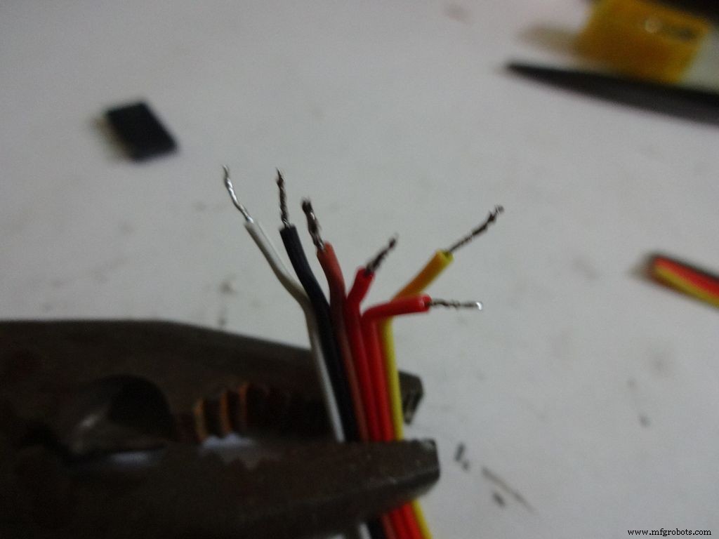 <図>
<図> 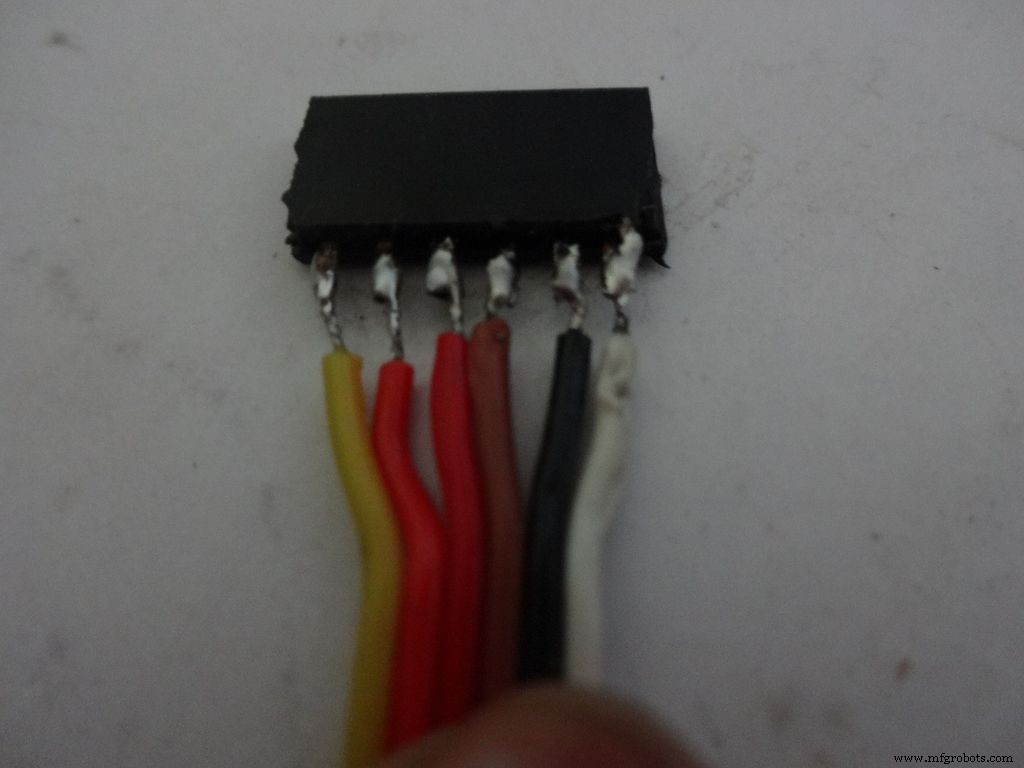 <図>
<図> 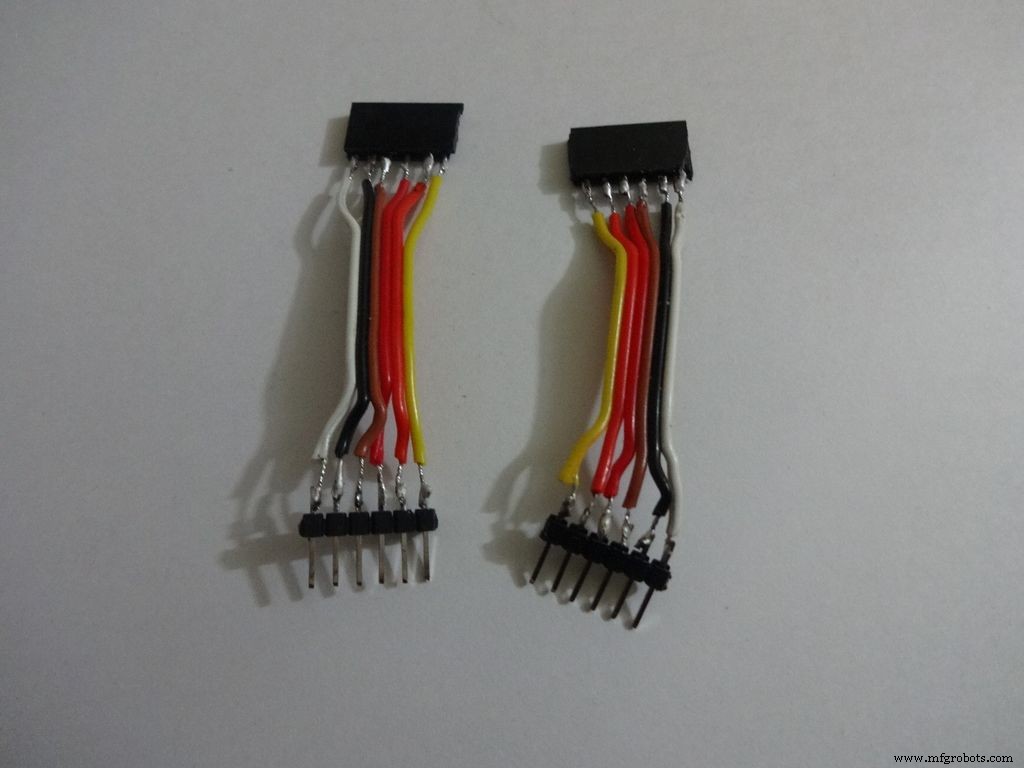 <図>
<図> 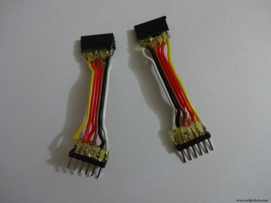
LCDの最初の6ピンと最後の6ピンを使用します。ピン D0-D3 未使用です。そのため、使用済みピンのみのコネクタを作成します。ビルドが完了すると、16ピンコネクタの抜き差しが非常に困難になるため、同じことを行うことをお勧めします。
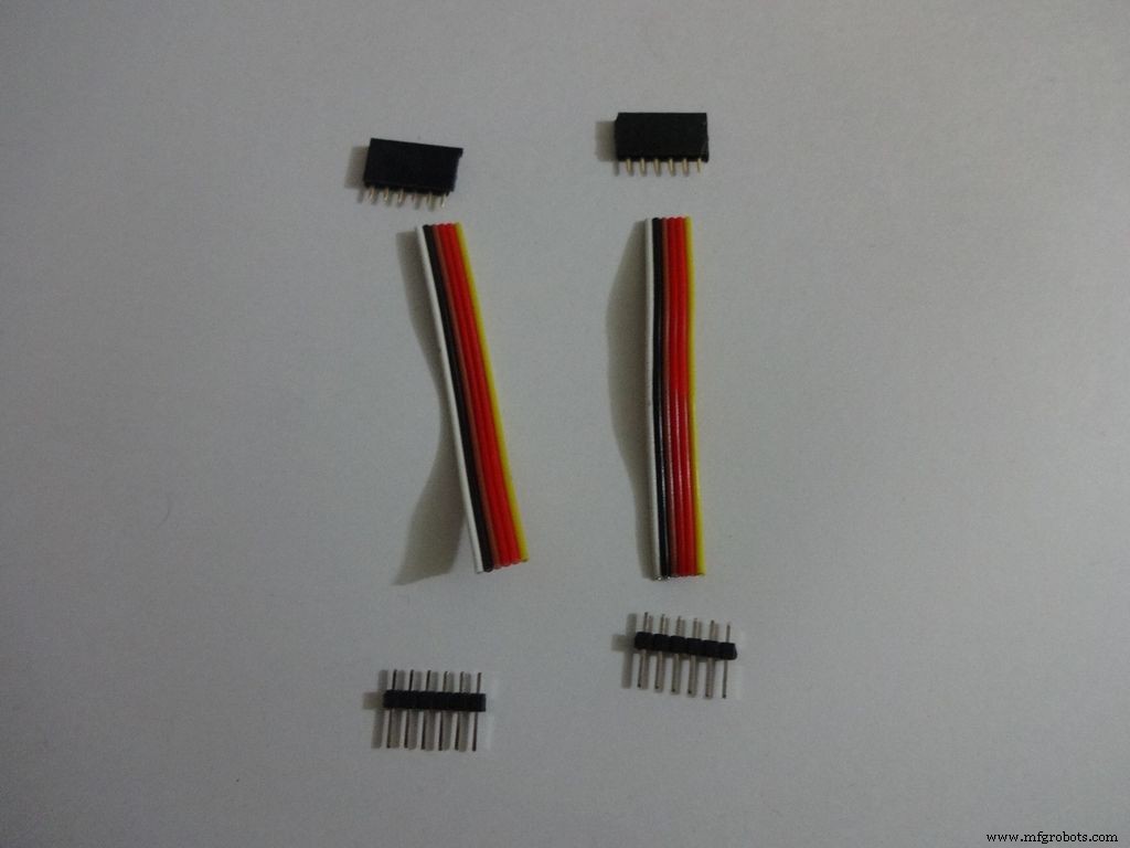
2x6ピンメスおよびオスヘッダーピンをカットします。また、長さ約2〜2.5インチの6線リボンケーブルを使用します。
絶縁体を剥がし、リードに錫メッキします。また、ヘッダーピンを錫メッキします。スライドスイッチのように1つずつ結合します。
ホットグルーを塗布してワイヤーを固定します。
ステップ19:回路基板-LCD接続 <図>
 <図>
<図> 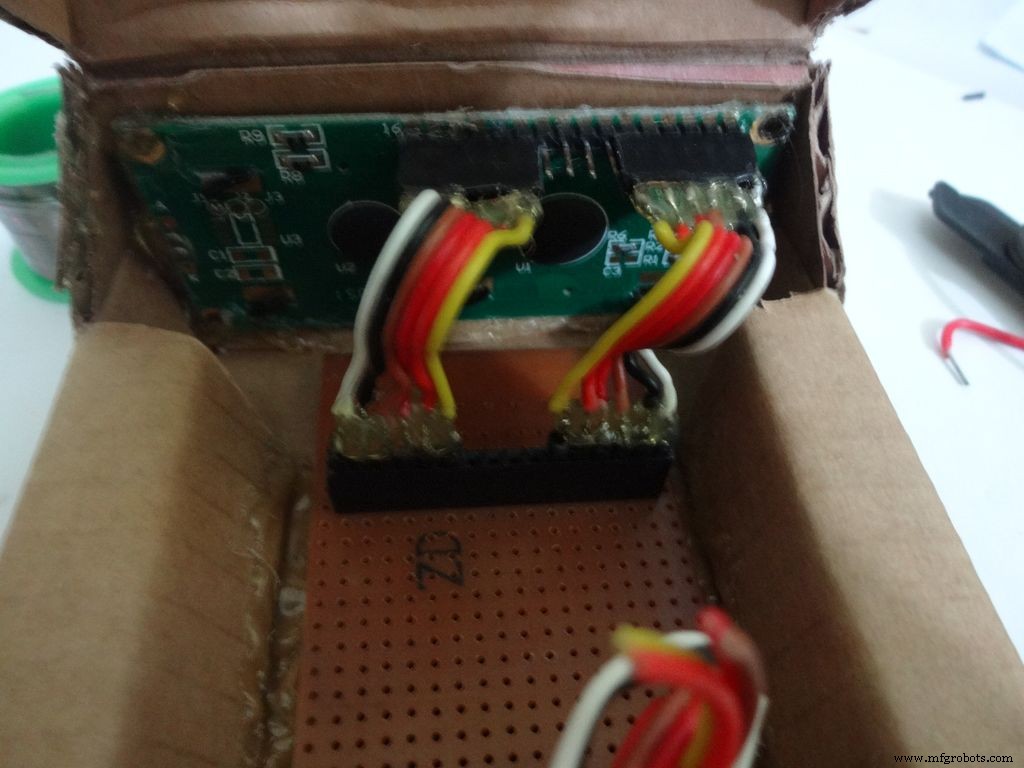 <図>
<図> 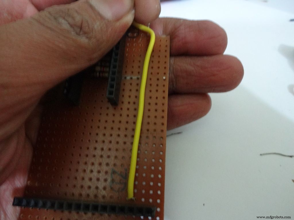 <図>
<図> 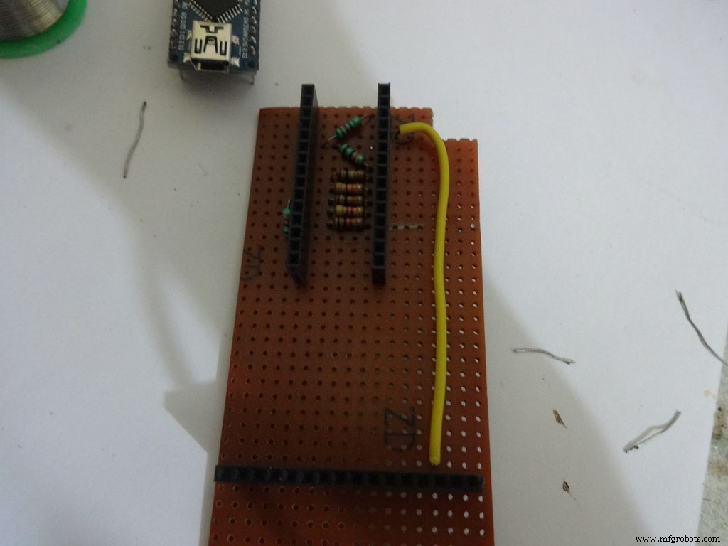 <図>
<図> 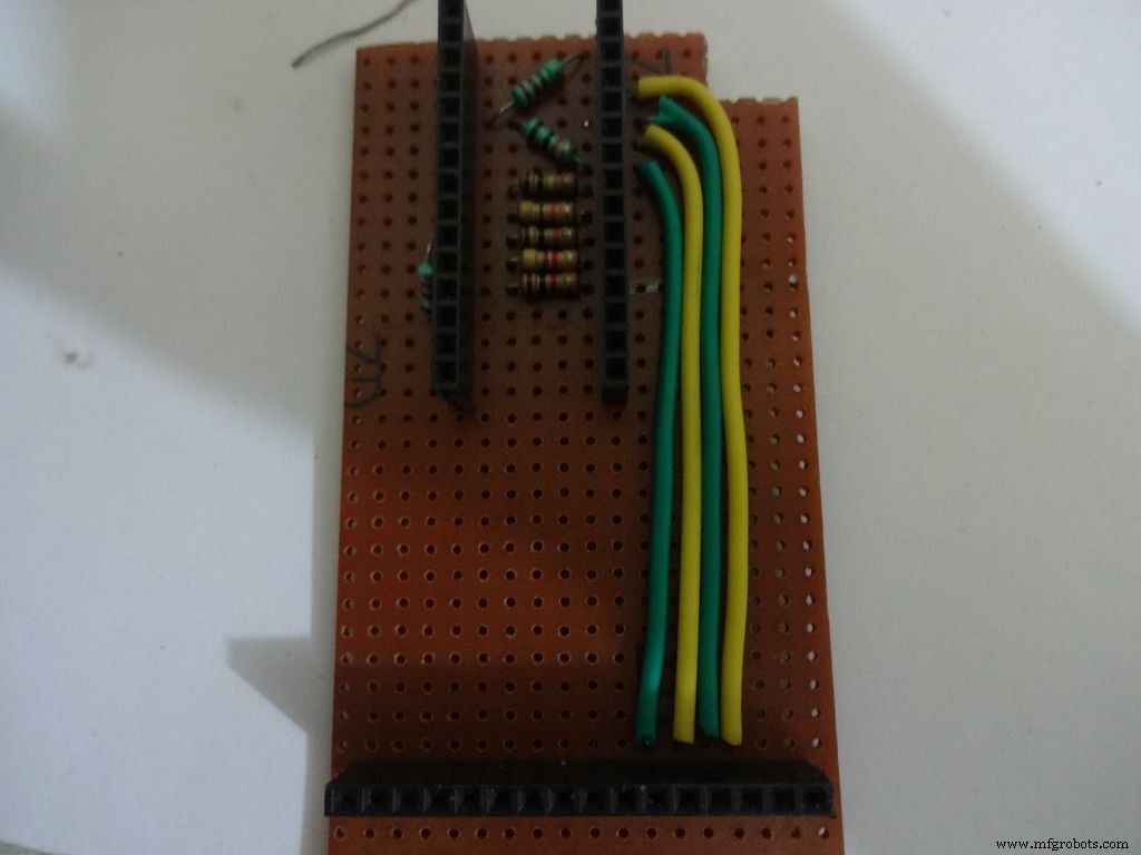 <図>
<図> 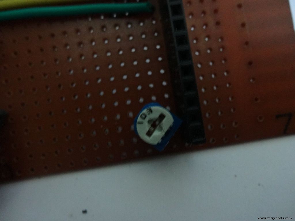 <図>
<図> 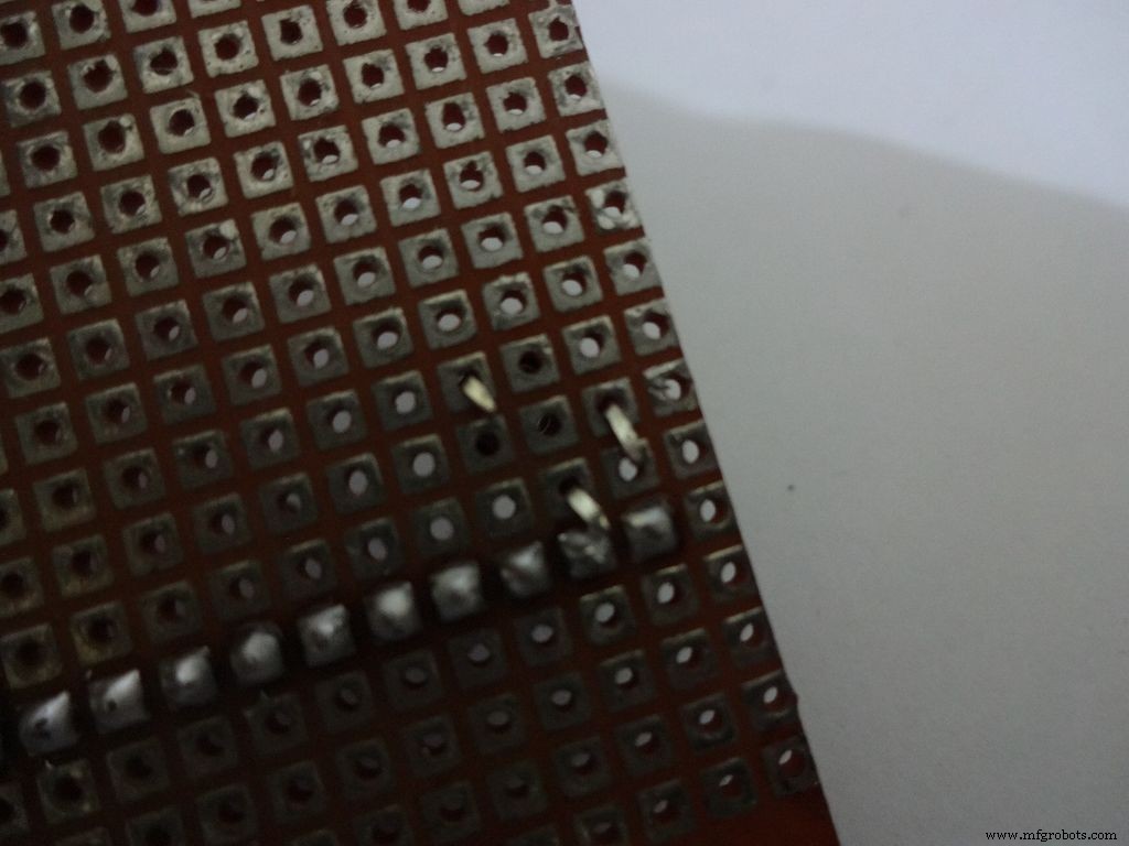 <図>
<図> 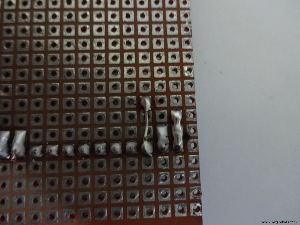 <図>
<図> 
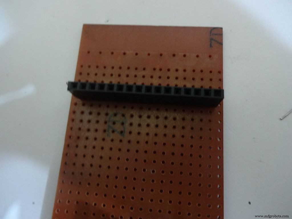
PCBをケース内に配置します。コネクタをLCDに接続し、PCBのメスポートの位置を確認してはんだ付けします。
LCDポートの後ろに4〜5ドットの行を残してください。電源スイッチは後でここに追加されます。
データピンを接続するために必要な一本撚り線の長さを測定します( D4 、 D5 、 D6 および D7 )LCDからデジタルピン( D7 、 D8 、 D9 および D10 )それぞれArduinoで。
サイドエンドが Vcc になるように、10kオームのポテンショメータを追加します。 、GNDおよび V0 への真ん中のピン 。
Vss(GND)を接続します LCDで GND 、および Vdd + 5V 。 R / W も接続します GND 。
Arduinoピン
LCD
D7 D4 D8 D5 D9 D6 D10 D7 GND Vss(GND)+ 5V Vdd
ステップ20:回路基板-RTCモジュール <図>
 <図>
<図> 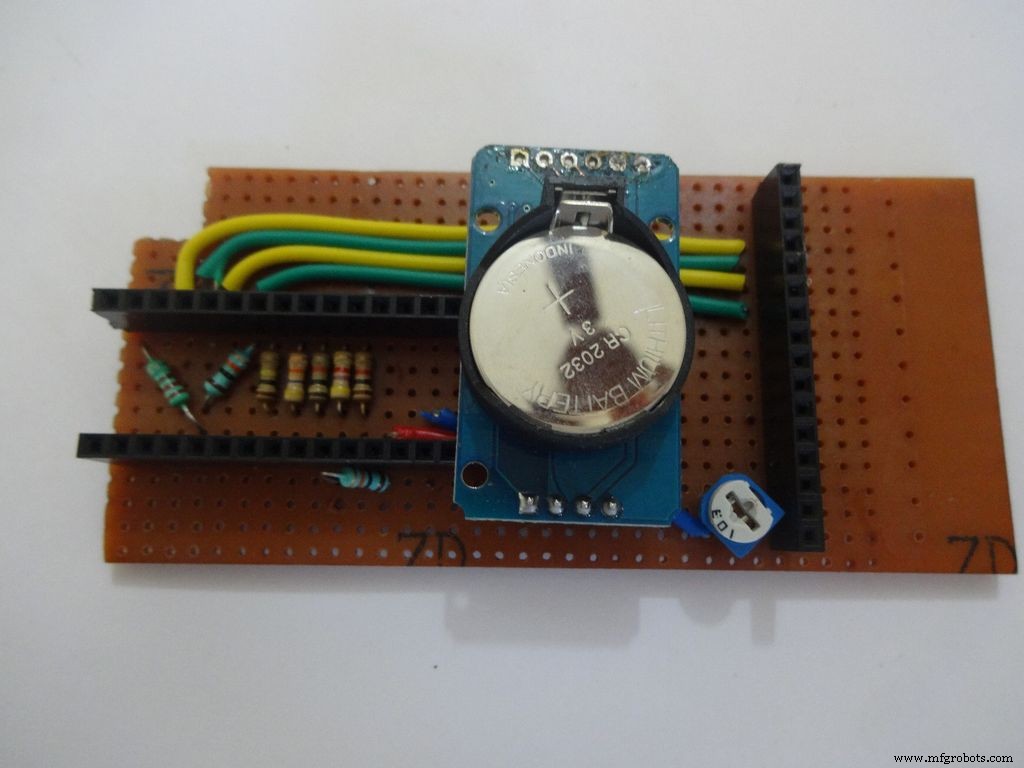 <図>
<図> 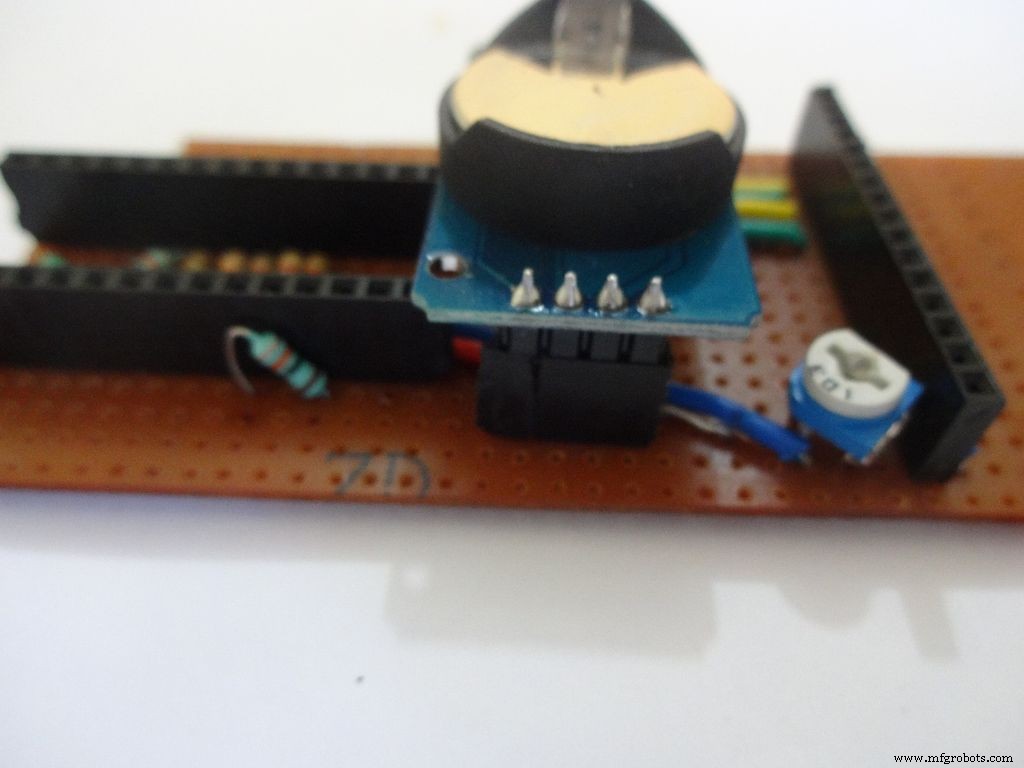 <図>
<図> 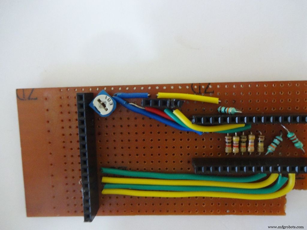
モジュールのデフォルトの90度ヘッダーピンをはんだ除去し、PCBに平らに収まるようにストレートピンを追加しました。
4ピンメスヘッダーピンをはんだ付けし、 Vcc に接続します 、 GND 、 SDA A4 および SCL A5 。
ステップ21:ケースの作成-モードボタン <図>
 <図>
<図> 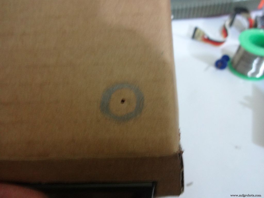 <図>
<図> 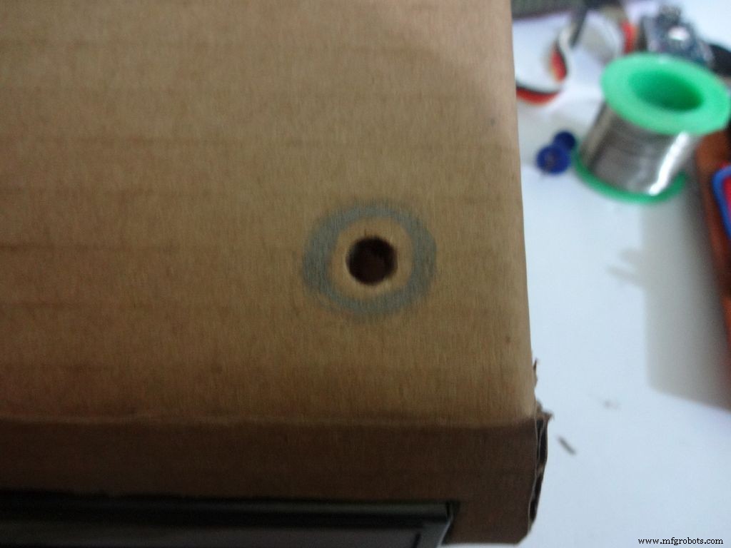 <図>
<図> 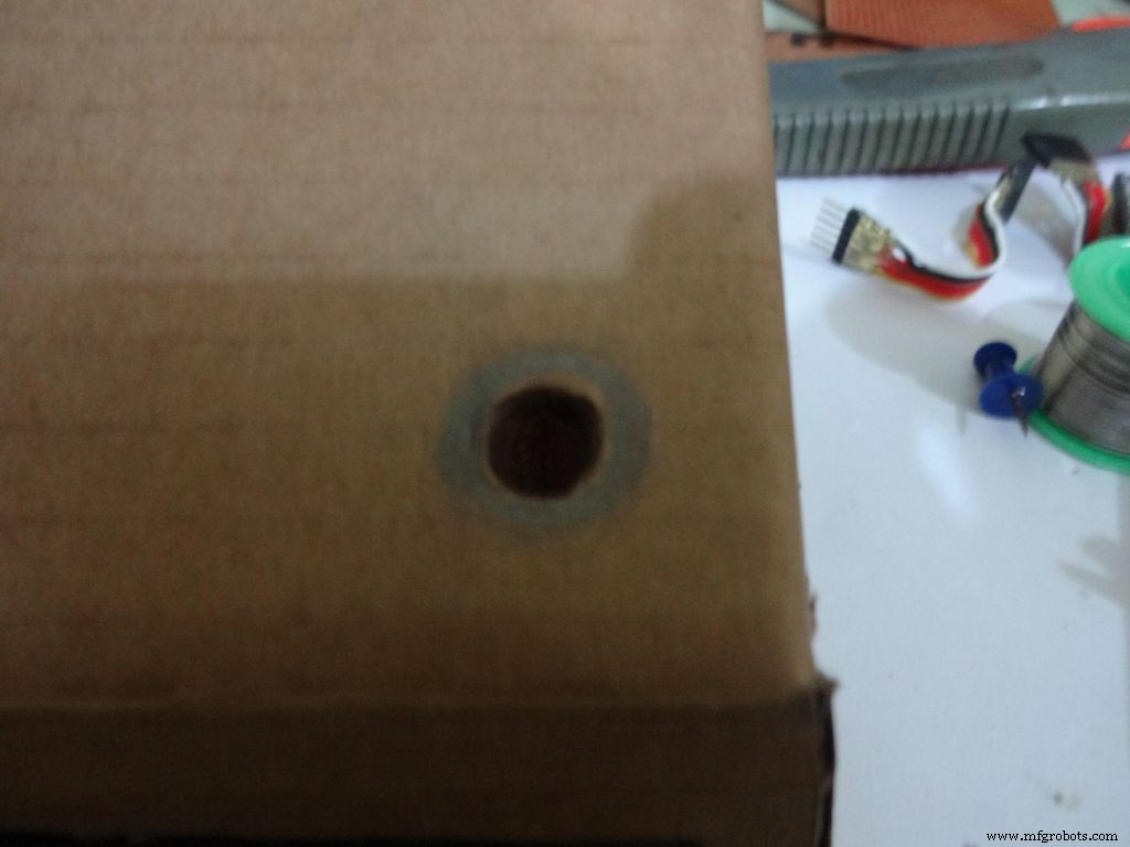 <図>
<図> 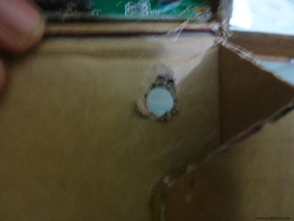 <図>
<図> 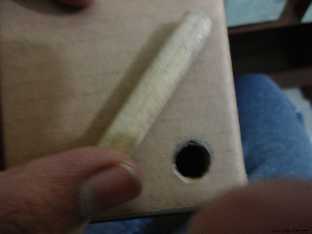 <図>
<図> 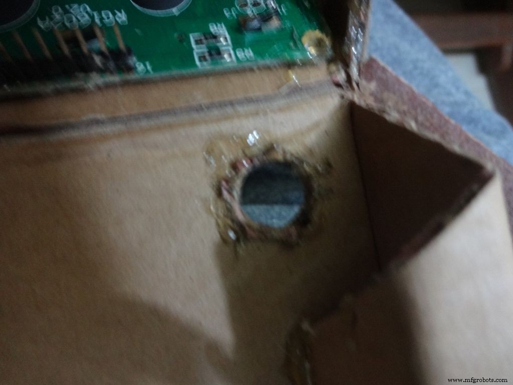 <図>
<図> 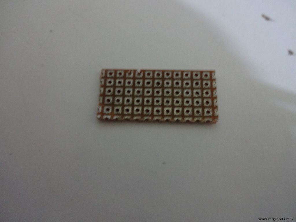 <図>
<図> 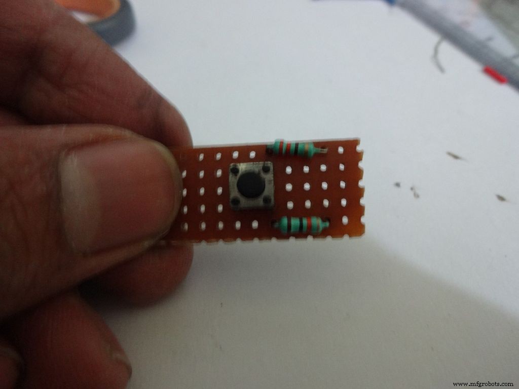 <図>
<図> 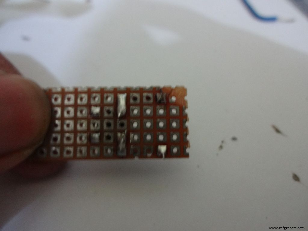 <図>
<図> 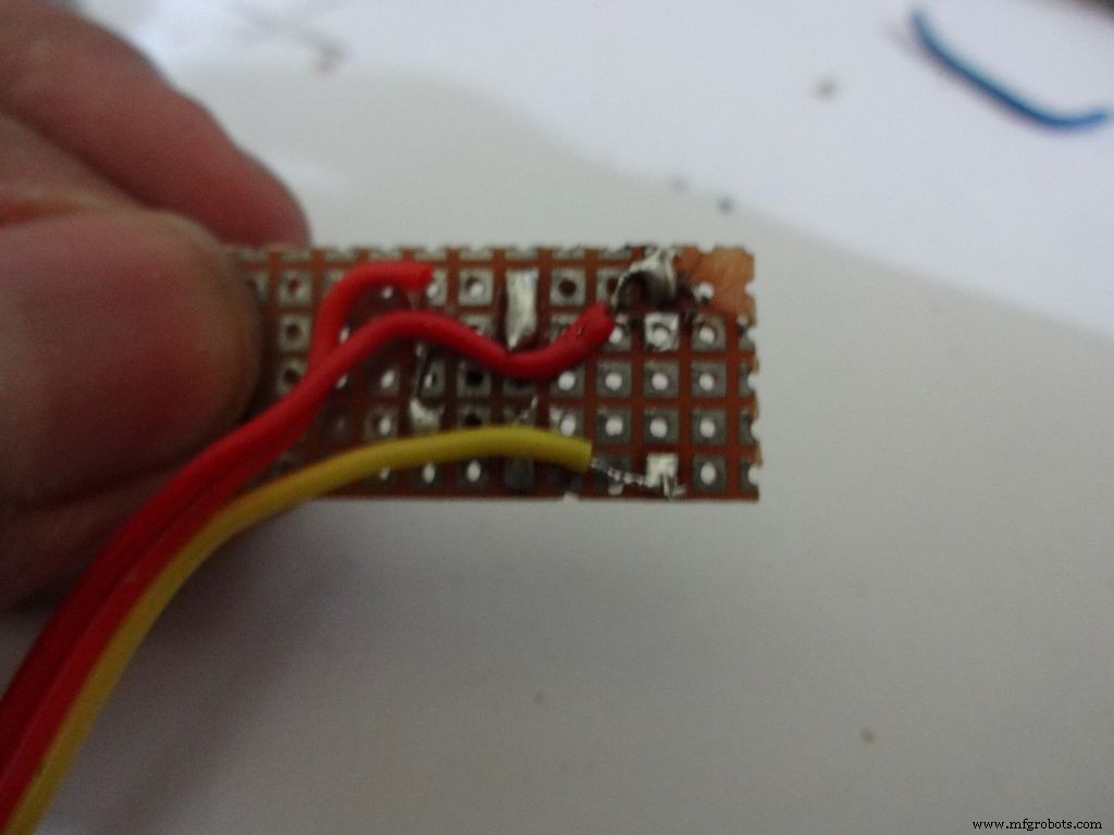 <図>
<図> 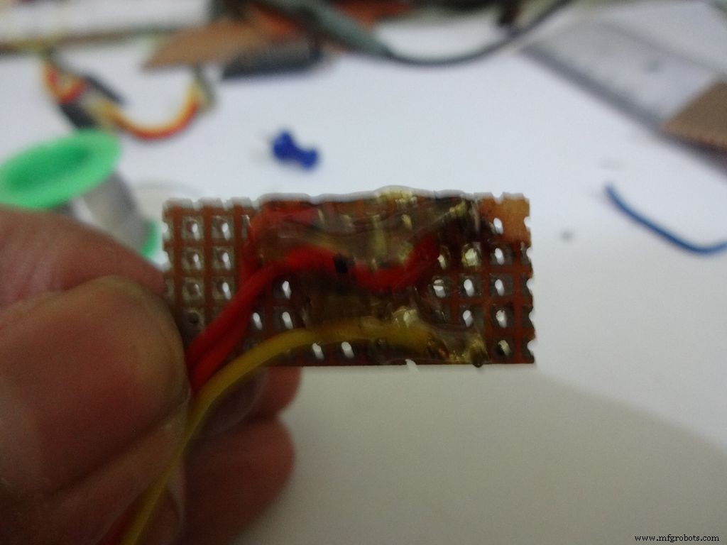 <図>
<図>  <図>
<図> 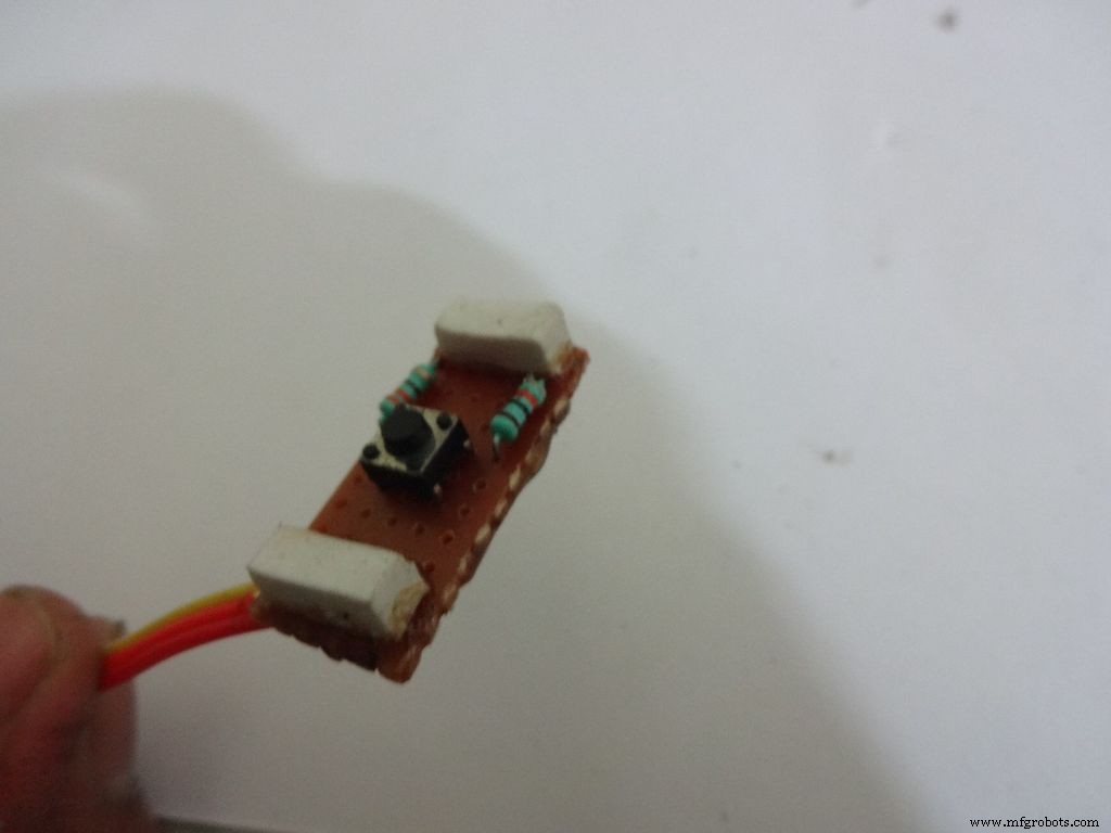 <図>
<図> 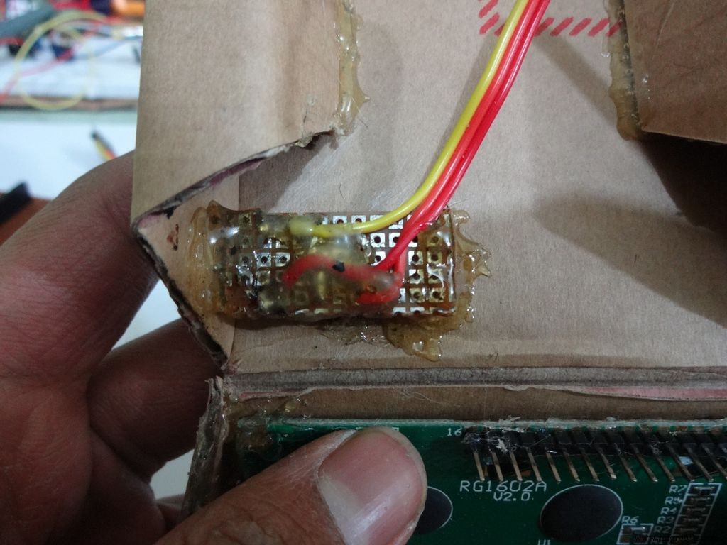 <図>
<図>  <図>
<図> 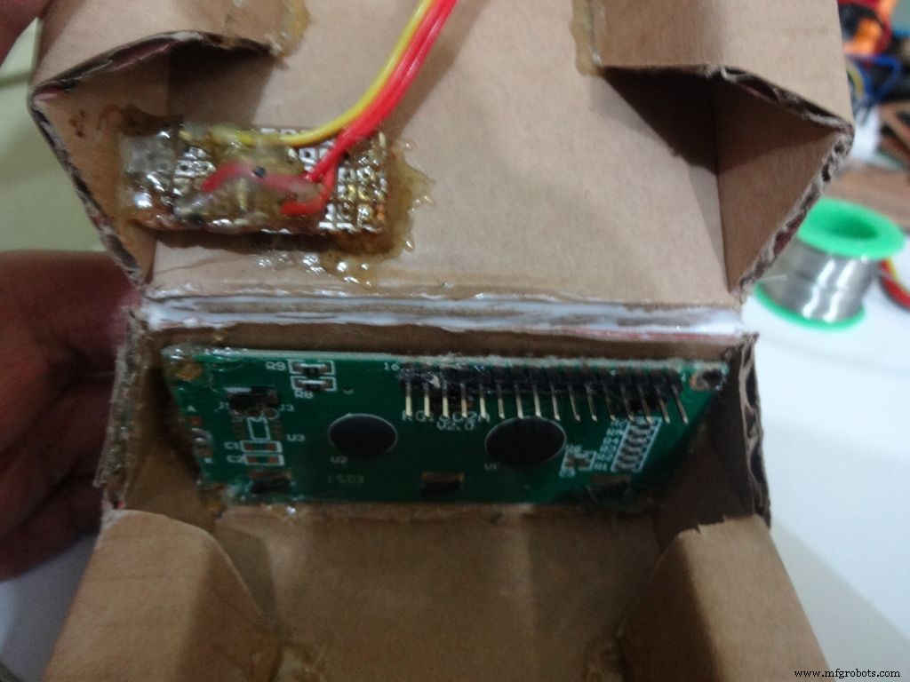
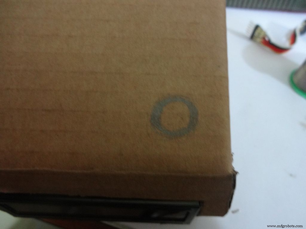
ICケースのピン1の角に直径約1cmの円をマークします。中央にピンで印を付け、鉛筆を使って拡大します。その後、適切なツールを使用して直径を1cmに増やします。内側に砂を塗り、ホットグルーを使用して穴を固定します。
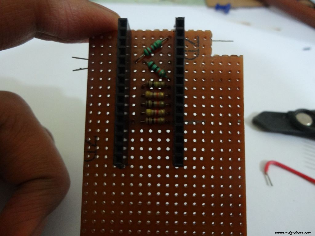
汎用PCB(10-11)ドットx5ドットをカットします。図のように、押しボタン、220および10kオームの抵抗器を接続してはんだ付けします。
約15cmの長さの3線リボンケーブルを取ります。図のように端を錫メッキし、はんだ付けします。どの色のワイヤーがどこに行くかを書き留めてください。これは後で役立ちます。
消しゴムを2つ切り、ボードの端に置きます。消しゴムの高さは、ボタンが外側から見て段ボールの内側のレベルより下になるようにする必要があります。 4mmを使用しました。
図のようにホットグルーで固定します
ステップ22:ケースの作成-テストポイント <図>
 <図>
<図> 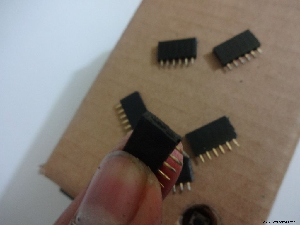 <図>
<図> 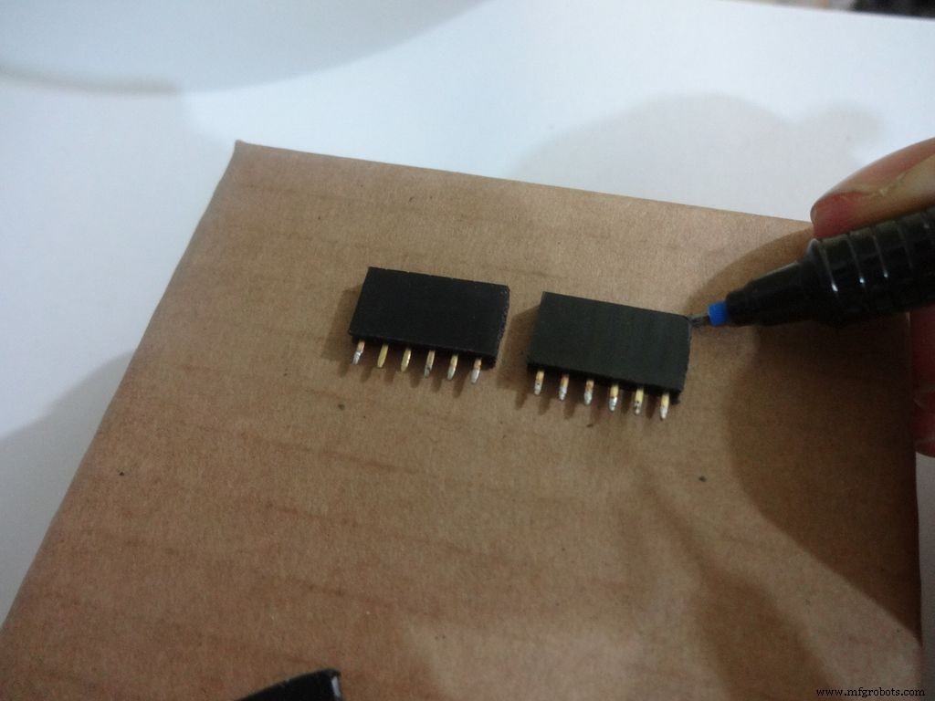 <図>
<図> 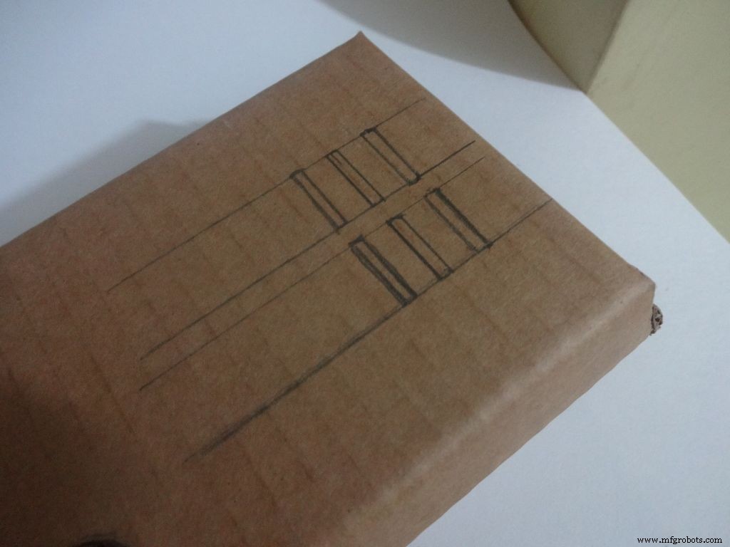 <図>
<図> 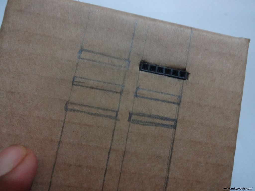 <図>
<図> 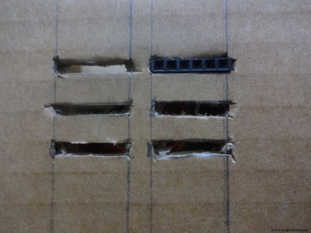 <図>
<図> 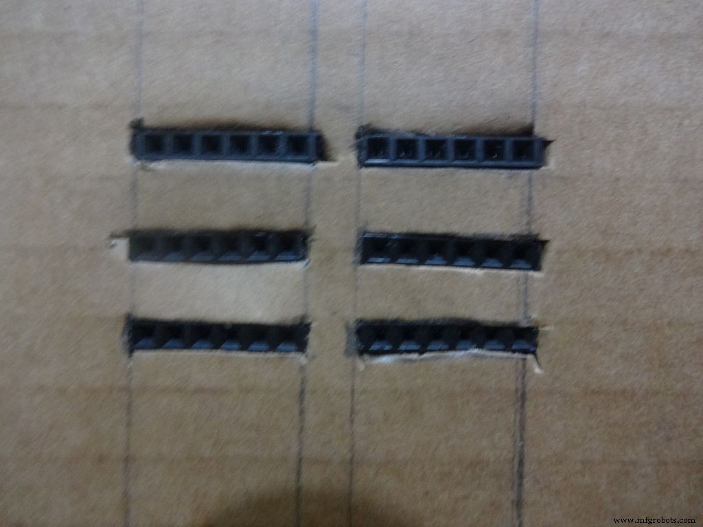 <図>
<図> 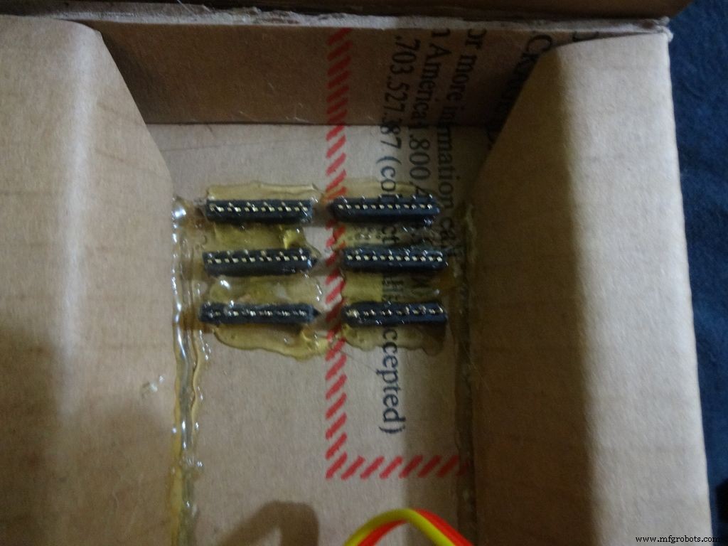 <図>
<図> 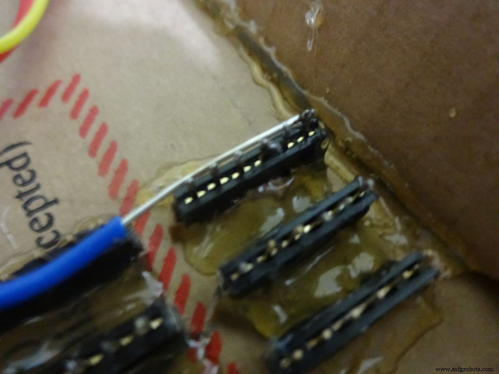 <図>
<図> 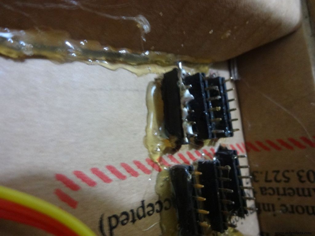 <図>
<図> 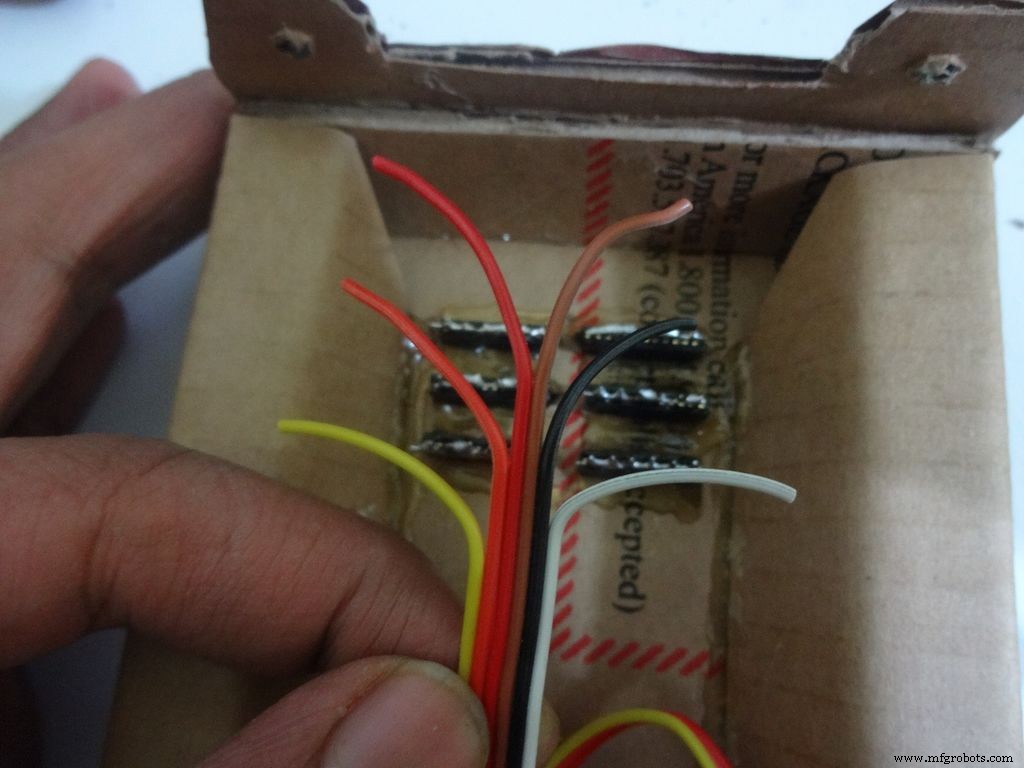 <図> <図>
 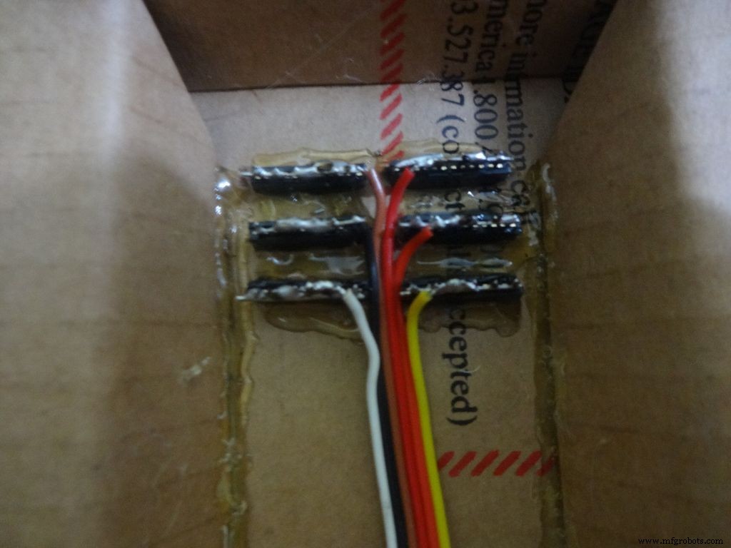 <図>
<図> 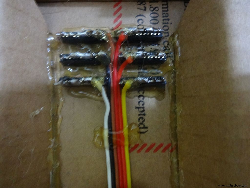
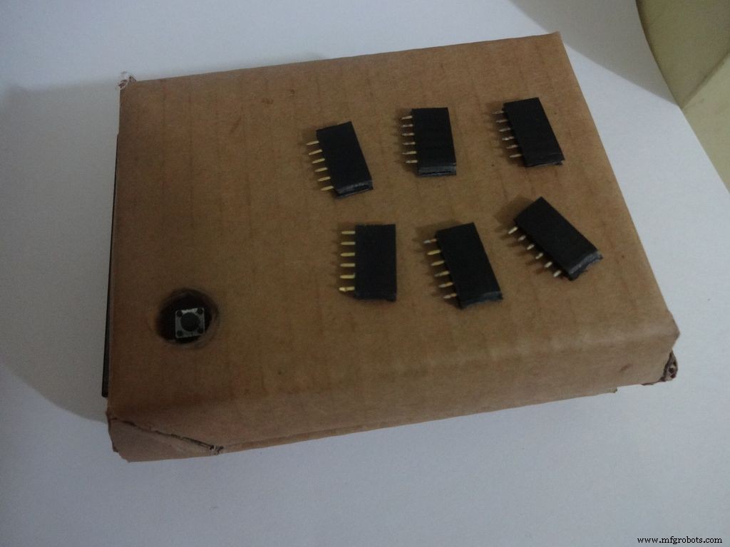
6x6ピンメスヘッダーピンをカットします。側面を研磨して滑らかにします。
ヘッダーピンの位置とカットスロットをマークします。所定の位置に挿入し、内側から接着します。
すべてのピンに少量のはんだを塗布し、剥がしたジャンパーを使用してすべてをまとめます。 すべてが接続されていることを確認してください。それを完璧にするためにそれを加熱し続けないでください。ピンを加熱すると、隣接するピンも加熱されます。
6本のより線のリボンケーブルを取り、それを錫メッキして各スロットに取り付けます。マイナス側に暗い色を入れていることに注意してください。ホットグルーを塗布して固定します。
ステップ23:脚 <図>
 <図>
<図>  <図>
<図> 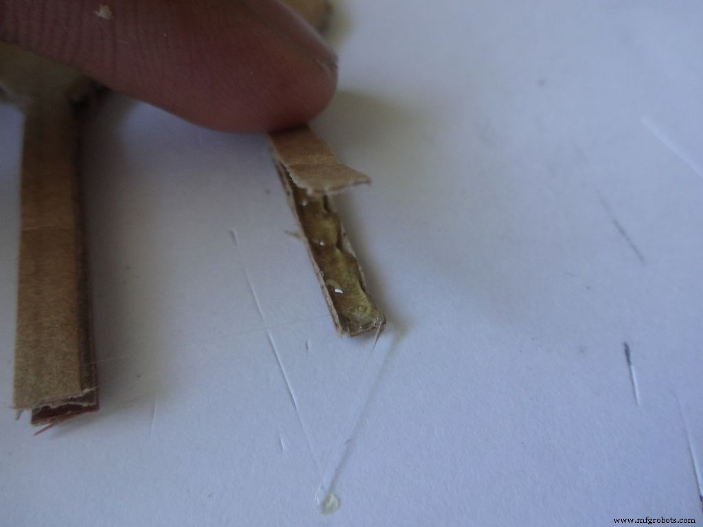 <図>
<図>  <図>
<図>  <図>
<図>  <図>
<図>  <図>
<図> 
お住まいの地域で利用可能な用紙サイズに基づいて、「Legs_A4.pdf」または「Legs_ANSI_A.pdf」をダウンロードしてください。最後に添付されています。
A4サイズの用紙(21 x29.7cmまたは8.27x 11.69インチ)または米国の代替ANSI A(8.5 x 11インチまたは21.6x 27.9cm)に印刷します。印刷中に、適切な用紙サイズと向きを選択し、[実際のサイズ]オプションを選択していることを確認してください。長方形を測定して、印刷が正確であることを確認します。 8.4 x11.8cmである必要があります
メインケースと同じように折り目を切り、接着します。画像を参照してください。
ステップ24:光沢を出す! <図>
 <図>
<図>  <図>
<図>  <図>
<図>  <図>
<図>  <図>
<図>  <図>
<図>  <図>
<図>  <図>
<図> 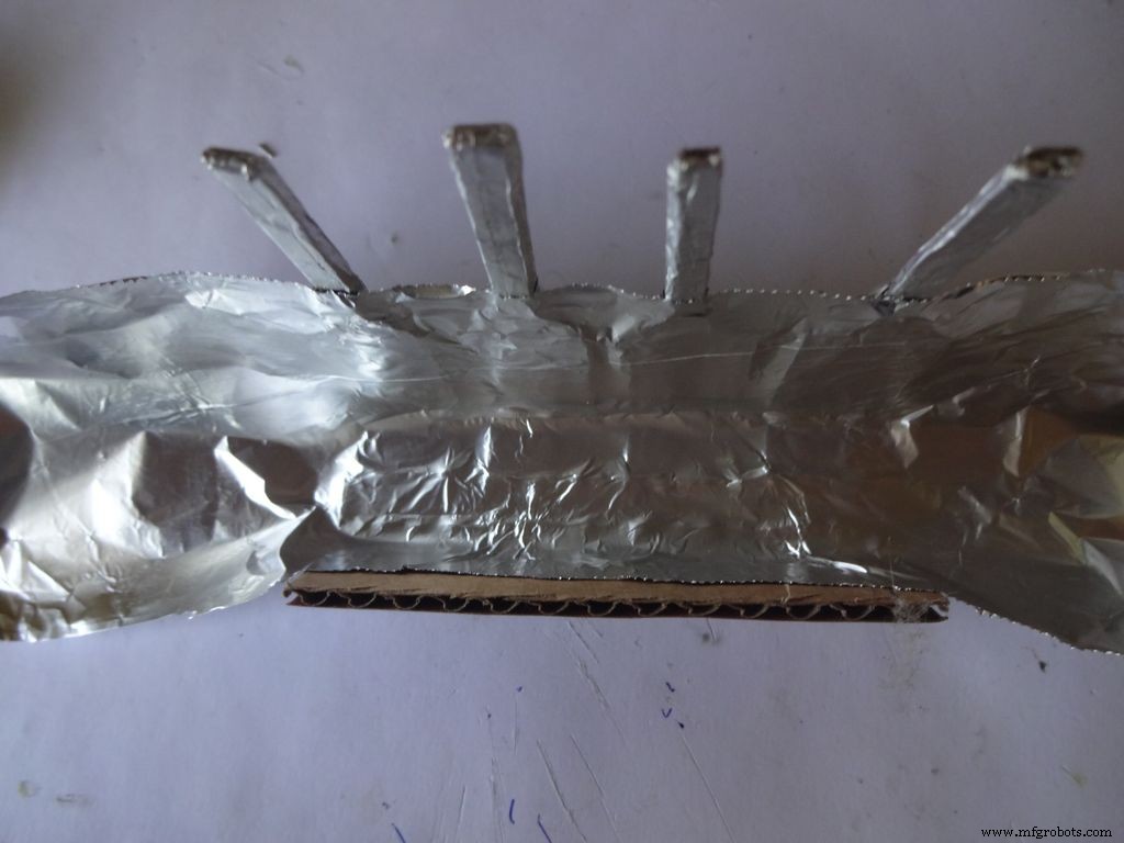 <図>
<図> 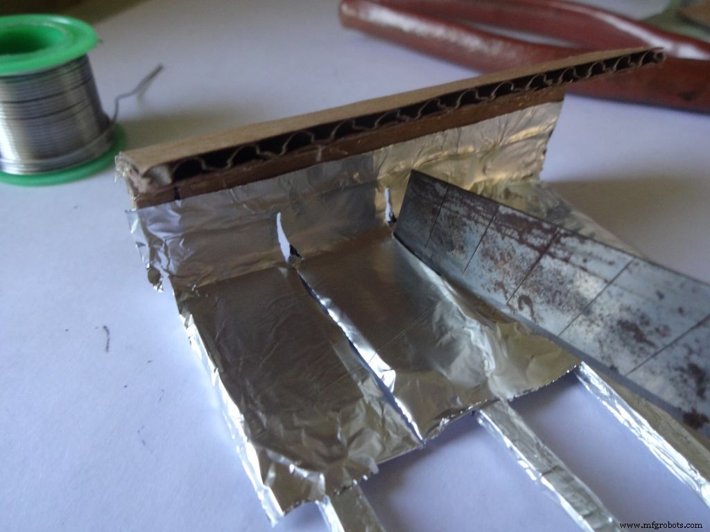 <図>
<図> 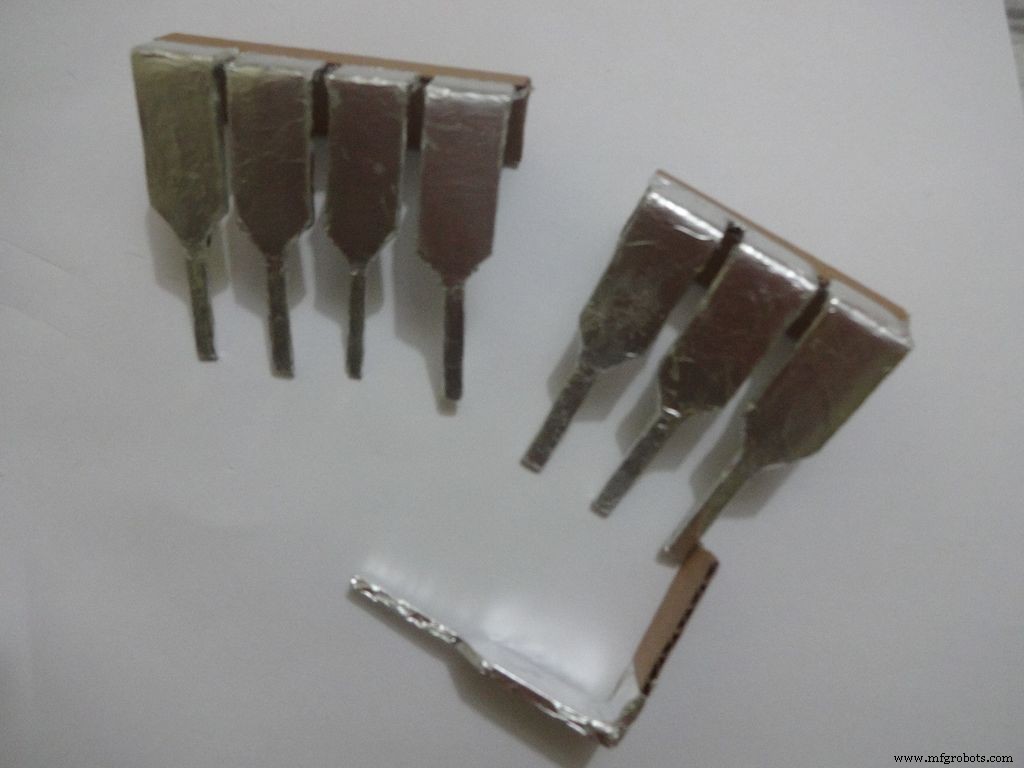 <図>
<図> 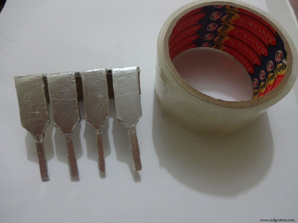 <図>
<図>  <図>
<図>  <図>
<図> 
ホイルを1x2インチに切り、慎重に貼り付けます。金属製の段ボールのスティックのりで脚の端まで折ります。 Fevibondを使用しました。
次に、すべてのレッグトップを覆うパッチを貼り付け(図を参照)、カッターでゆっくりとカットします。 これは慎重に行ってください。ホイルは側面に裂ける傾向があります。 平らなものを使用して、フォイルを脚の間に貼り付け、良い仕上がりにします。
次に、ホイルを貼ったのと同じように、透明なセロテープで覆い、鋭利なものから保護します。
ステップ25:電源スイッチ <図>
 <図>
<図>  <図>
<図>  <図>
<図>  <図>
<図>  <図>
<図>  <図>
<図> 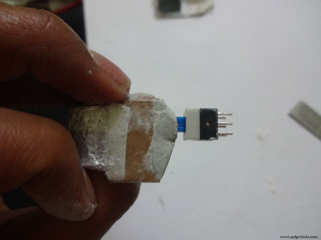 <図>
<図> 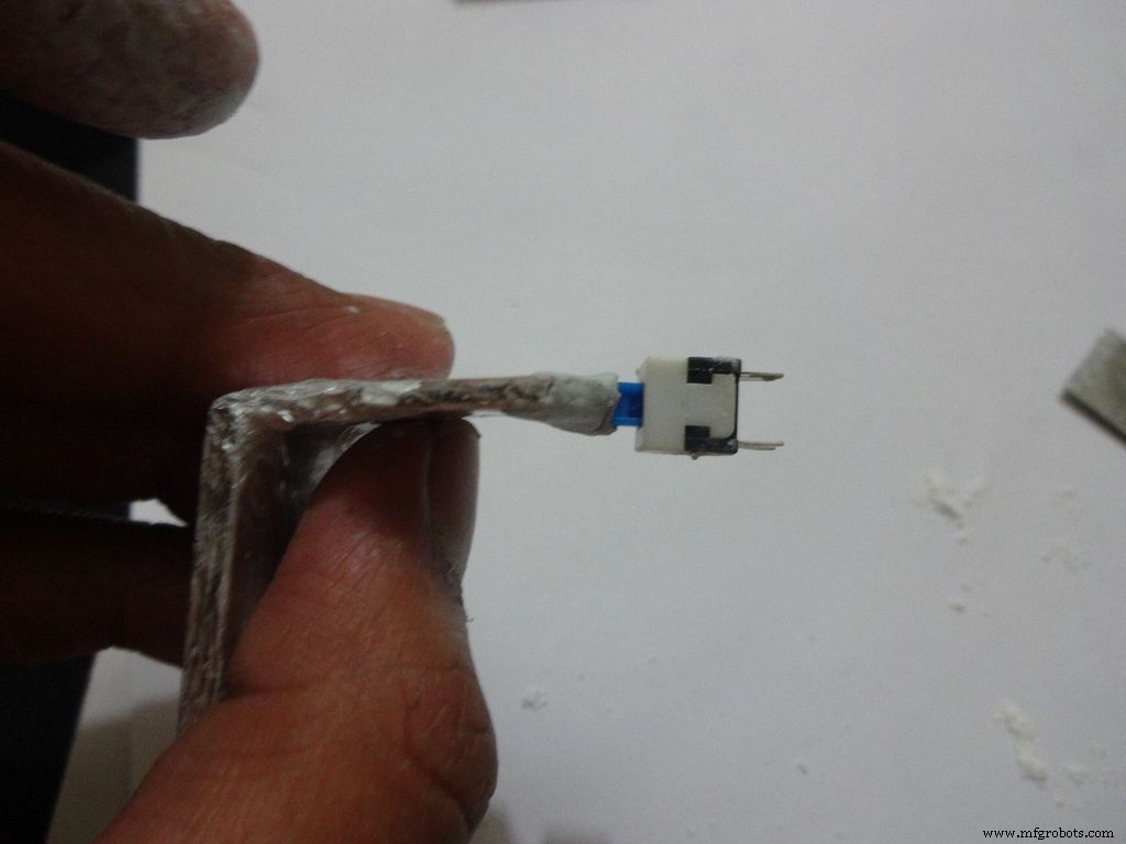 <図>
<図> 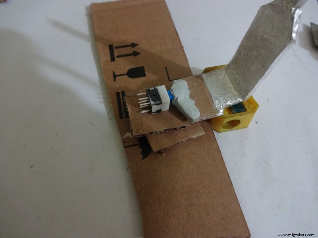 <図>
<図> 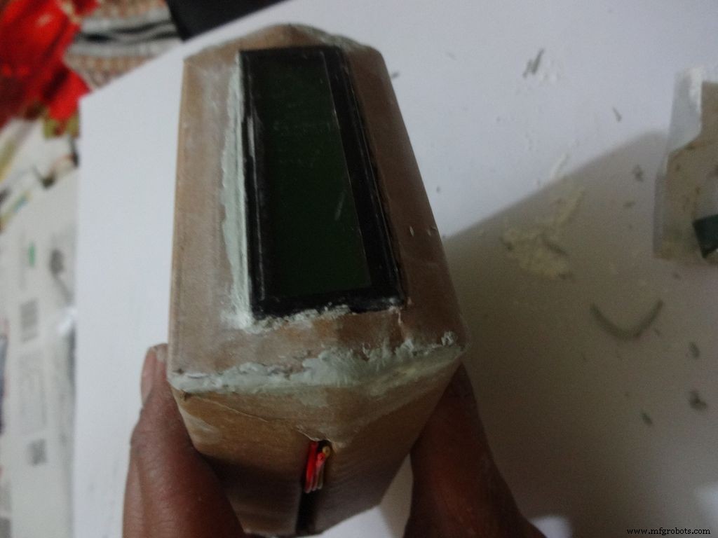 <図>
<図> 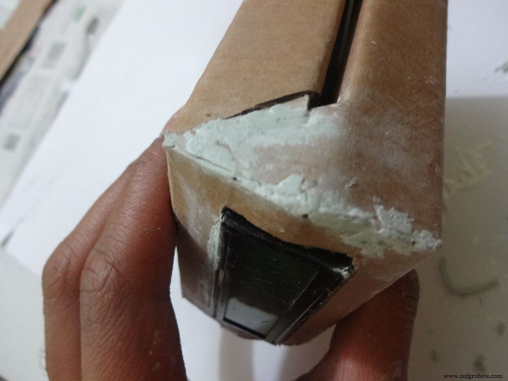 <図>
<図> 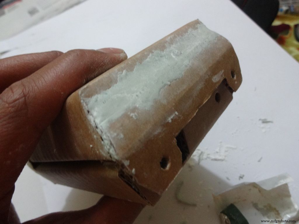
Measure and cut the power switch leg by properly keeping it in place. Temporarily stick the other pins with tape to get the pin1 position right.
Mix the m-seal(epoxy putty sealant, gets very hard when it dries) well. Put it as shown in the images and use powder+flat surface to shape it. Let it dry.
Also fill any gaps left in your case.
Note:We cant use hot glue here as it is rubbery and the switch needs to be stuck with some strong brittle material.
Step 26:Power switch to PCB <図>
 <図>
<図> 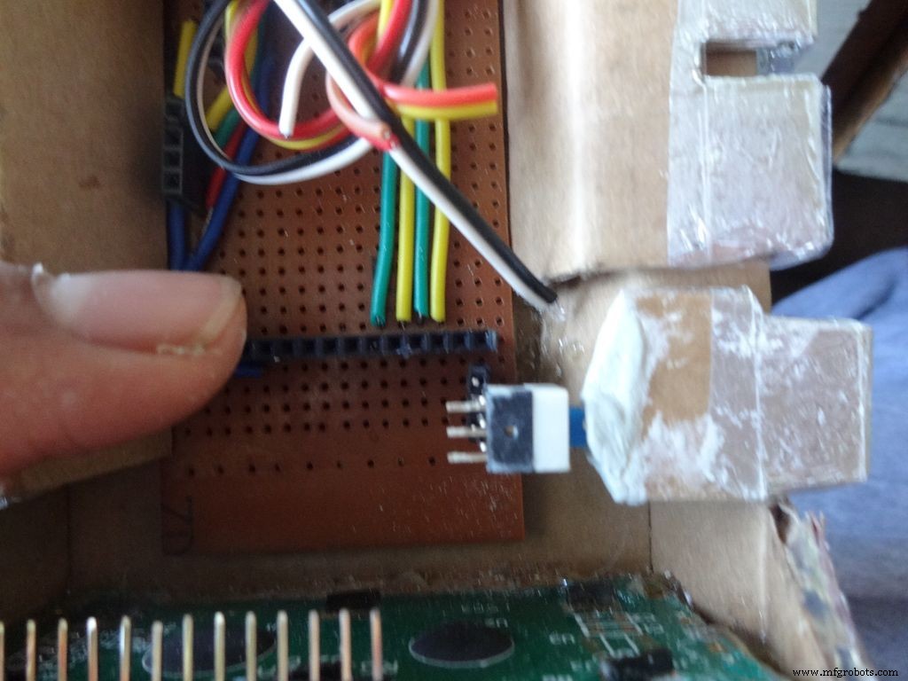 <図>
<図> 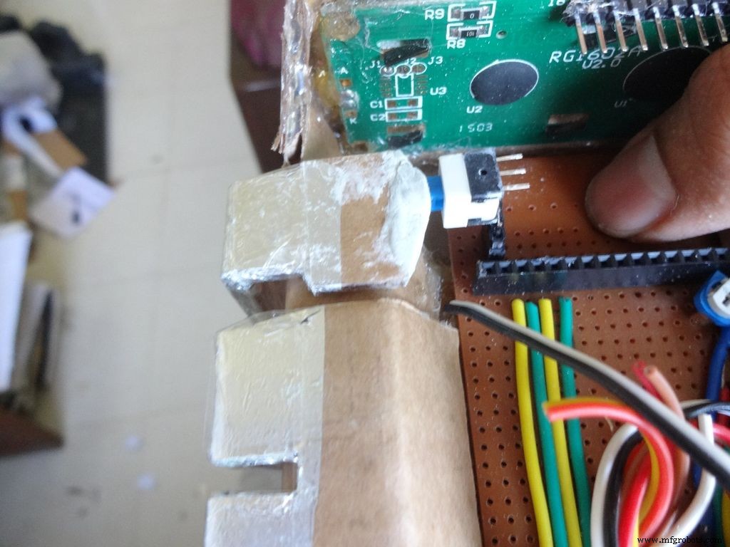 <図>
<図> 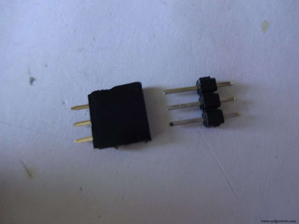 <図>
<図> 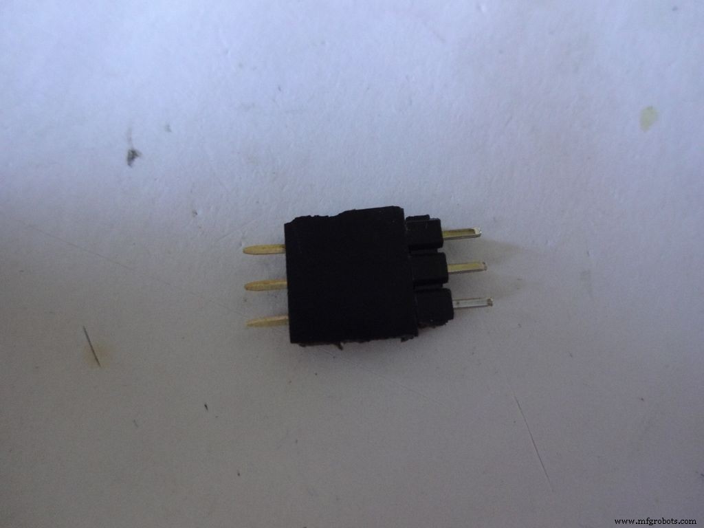 <図>
<図> 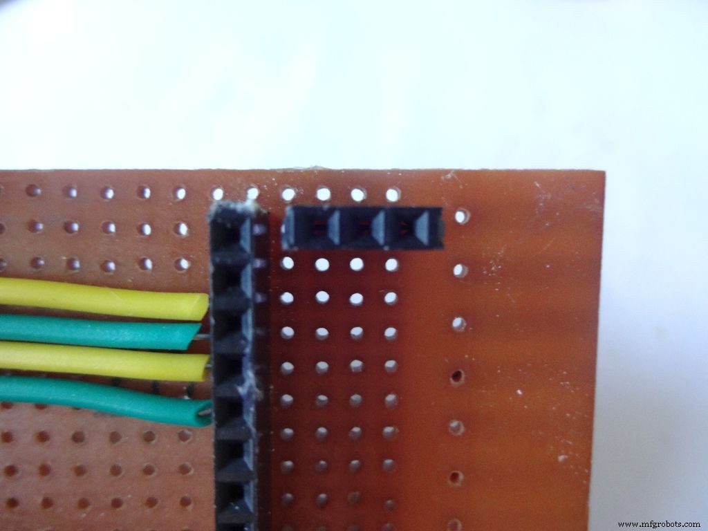 <図>
<図>  <図>
<図> 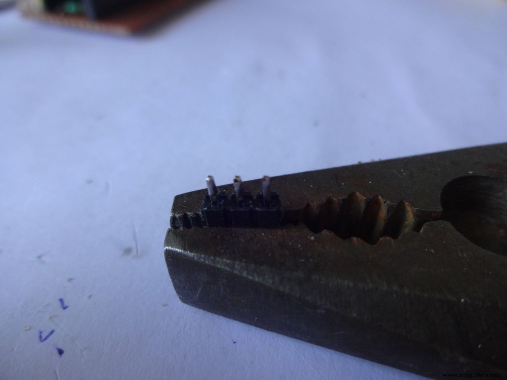 <図>
<図> 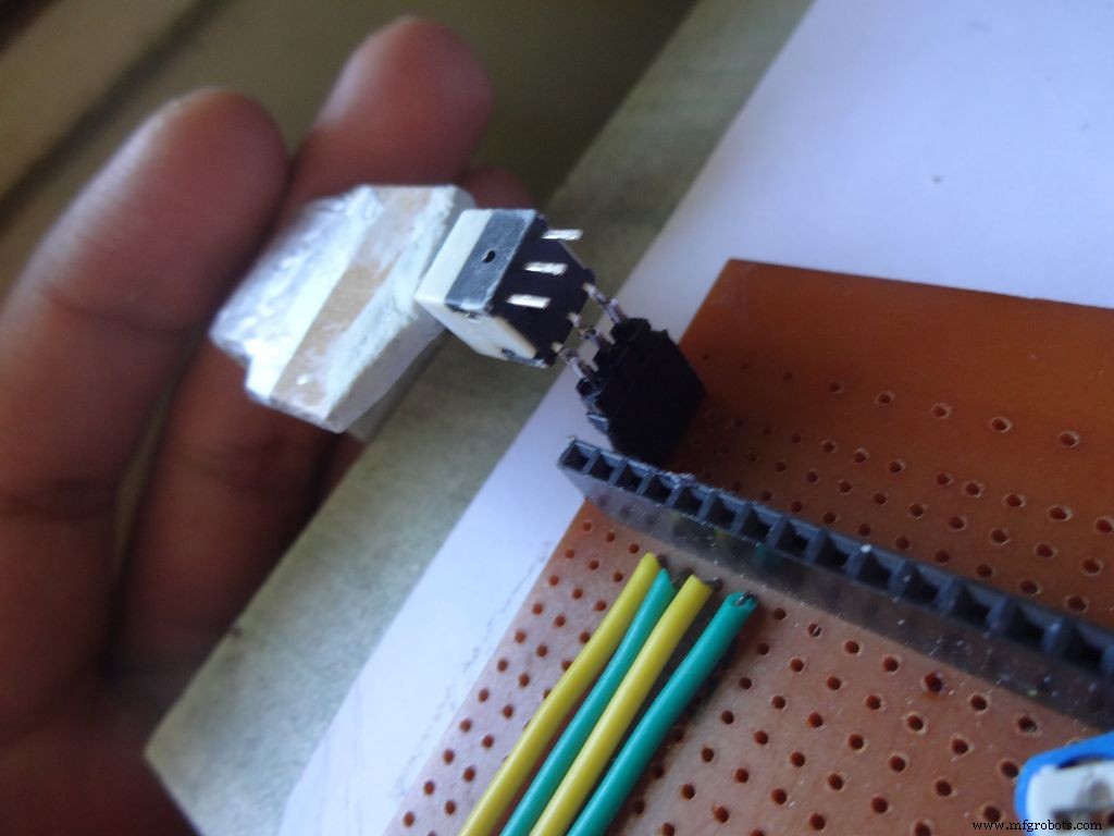 <図>
<図> 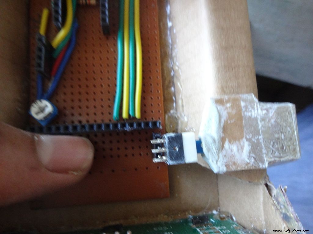 <図>
<図> 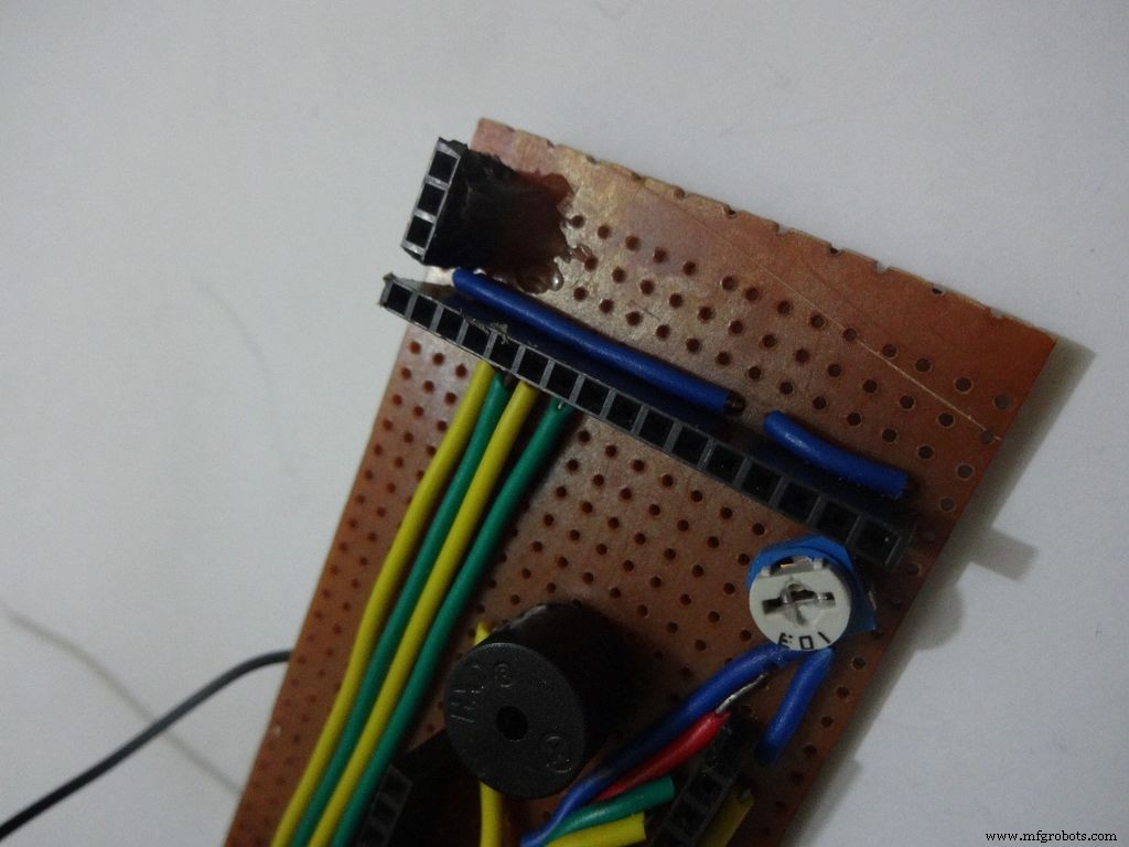
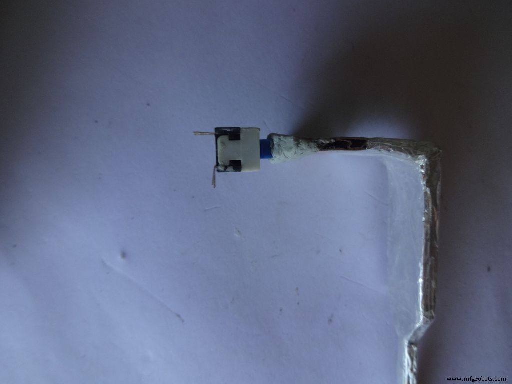
After The m-seal dries, place it in to check if everythings alright.
Cut 3pins of female and male headers place it on the PCB such that it aligns with the switch pins. Solder the female part.
Tin the switch leads and the male header pins, join them. See if it fits at the right place.
Try pushing the switch on and off after placing a finger behind the switch for support. We will add a support rod later on.
Connect a side pin of female header(power switch) to Vin. I realised this late and had to undergo lots of trouble.
Secure the header Pin with hot glue.
Step 27:Making the USB Port <図>
 <図>
<図> 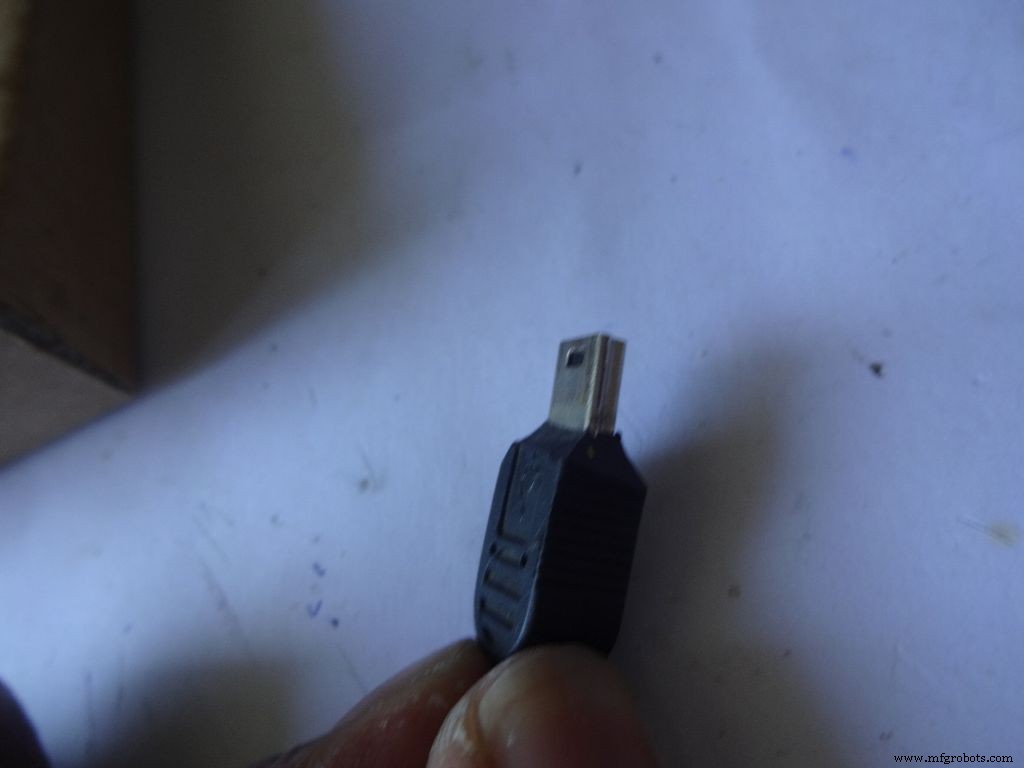 <図>
<図> 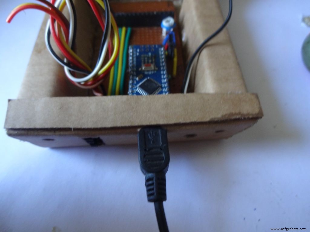 <図>
<図> 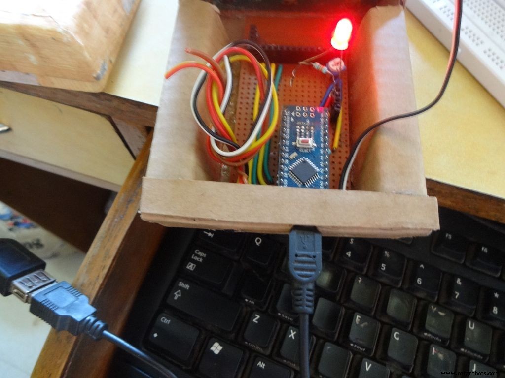
Put the PCB properly in (with Arduino) and cut a rectangle for the mini USB port.
Remove some plastic from the USB cable so that it fits the Arduino properly. Test whether connection is proper.
Step 28:Some other things... <図>
 <図>
<図> 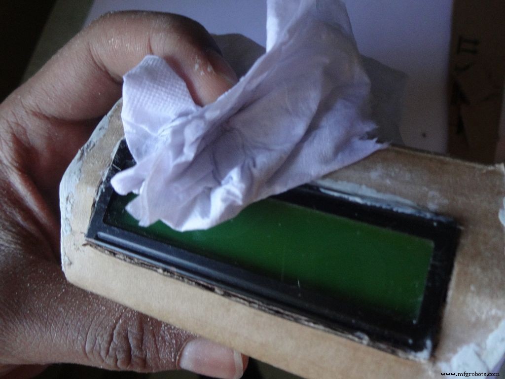 <図>
<図> 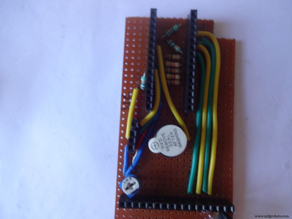
I removed all the LEDs from the Arduino Nano and also the power LED on my RTC module. These consume unnecessary power, which matters if you are operating on a battery.
Sand the dried m-seal so that it mixes smoothly with the cardboard. Clean the powder with a wet paper napkin before painting.
I also added a buzzer which may be used for some functions. Buzzers are sensitive, don't use too much heat while soldering!
Step 29:Time to paint! <図>
 <図>
<図> 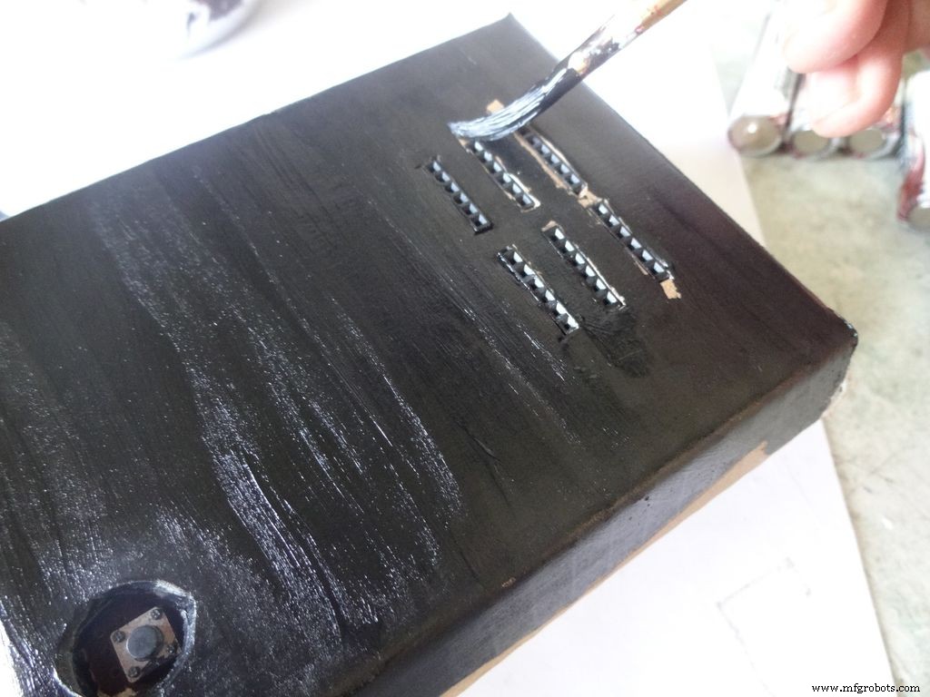 <図>
<図> 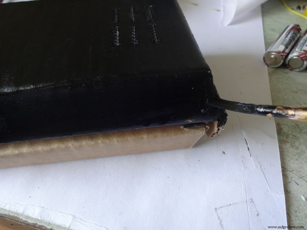 <図> <図>
 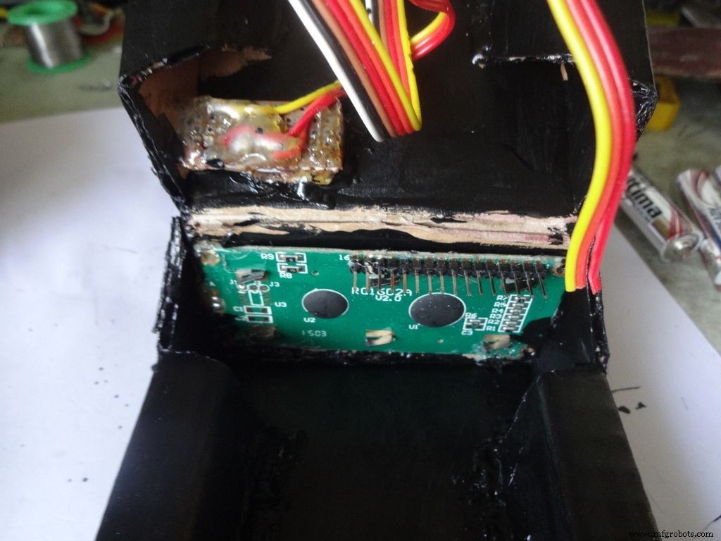 <図>
<図> 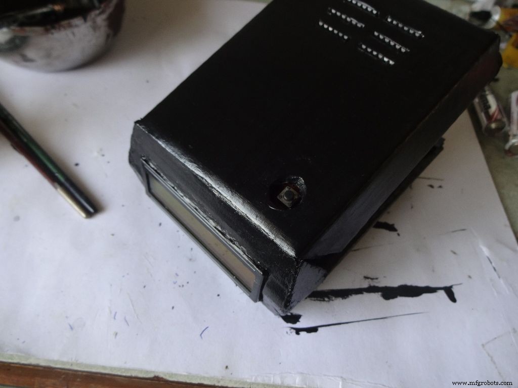
Dont use direct thick paint while painting, this cases brush patterns to appear. Use sufficient water.
Make sure no tiny bubbles are formed. These form when you dab the brush too much.
Dont paint the cover hinge, the paint will restrict it.
This is just a base coat. Another layer of paint will be added while finishing up.
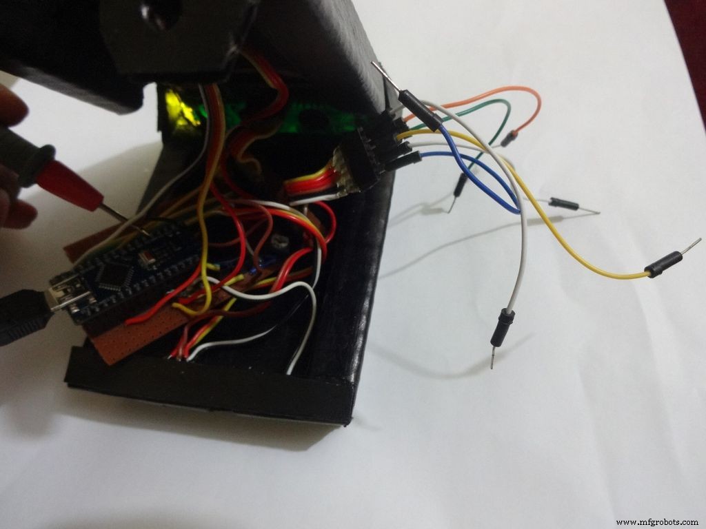
Step 30:Soldering all the wires <図>
 <図>
<図> 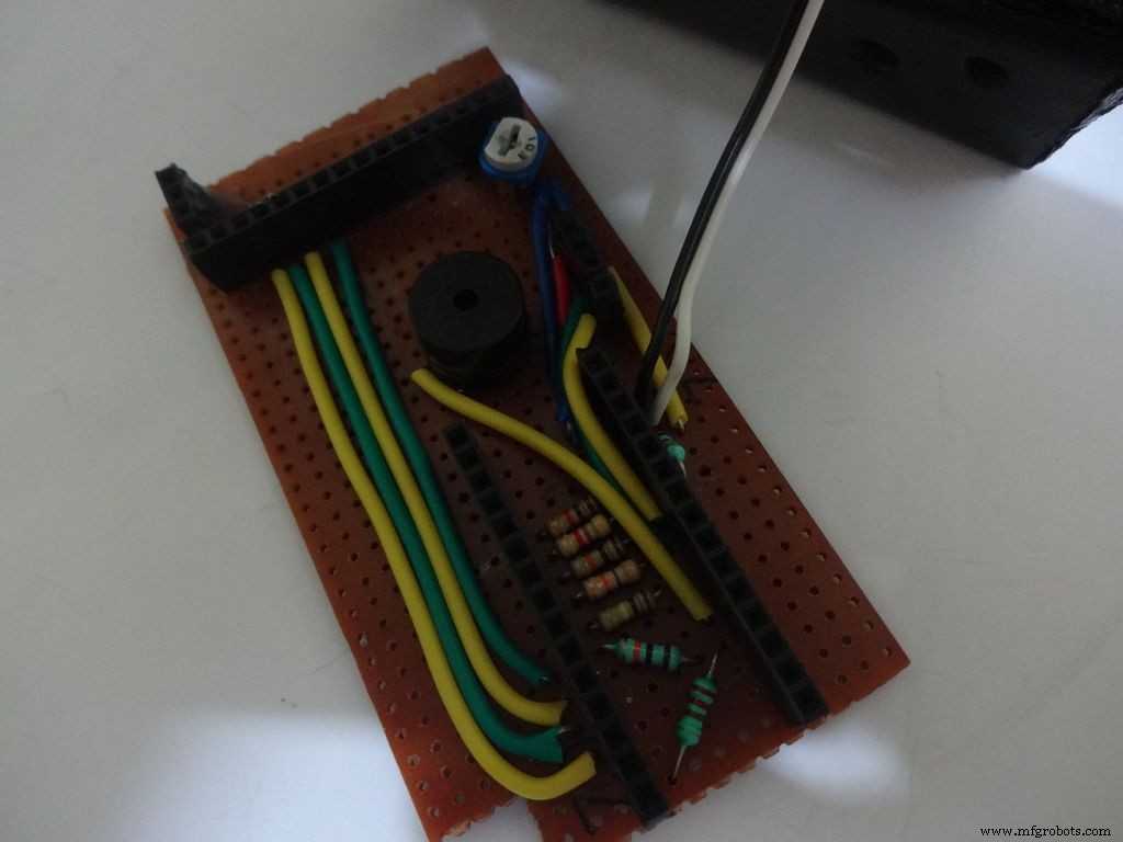 <図>
<図> 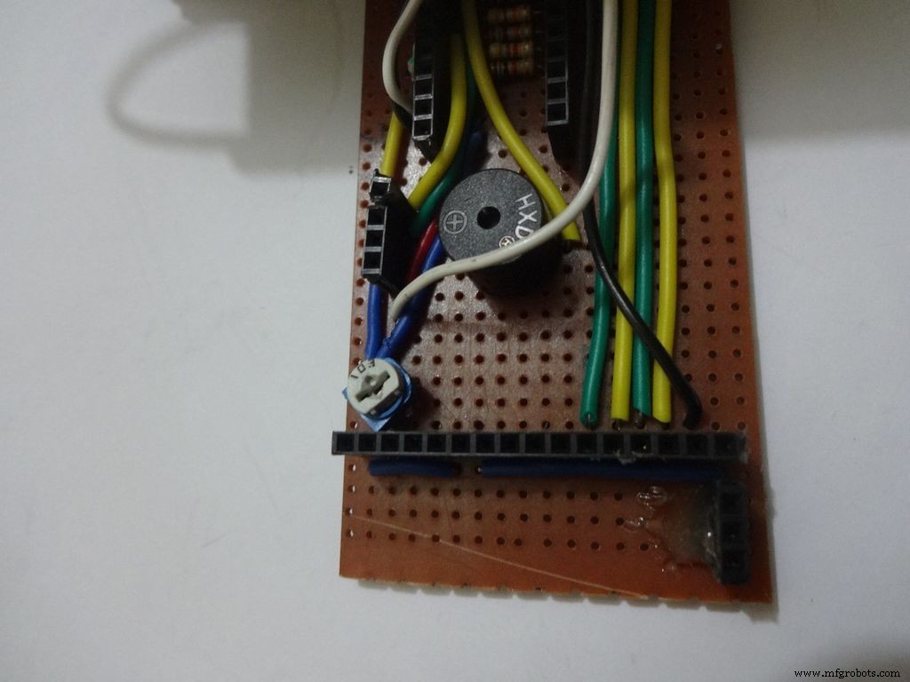 <図>
<図>  <図>
<図>  <図>
<図>  <図>
<図> 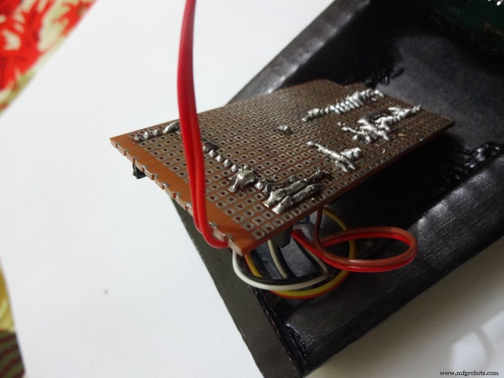 <図>
<図> 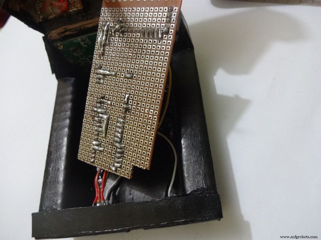 <図>
<図> 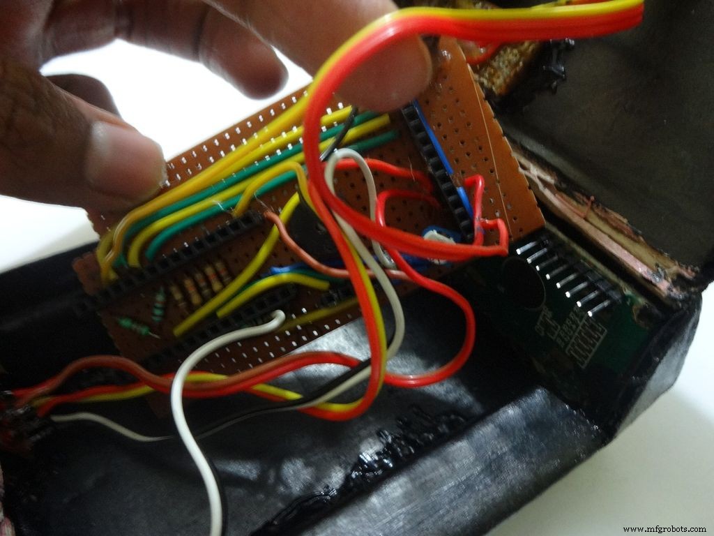 <図>
<図> 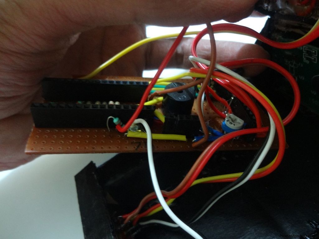 <図>
<図> 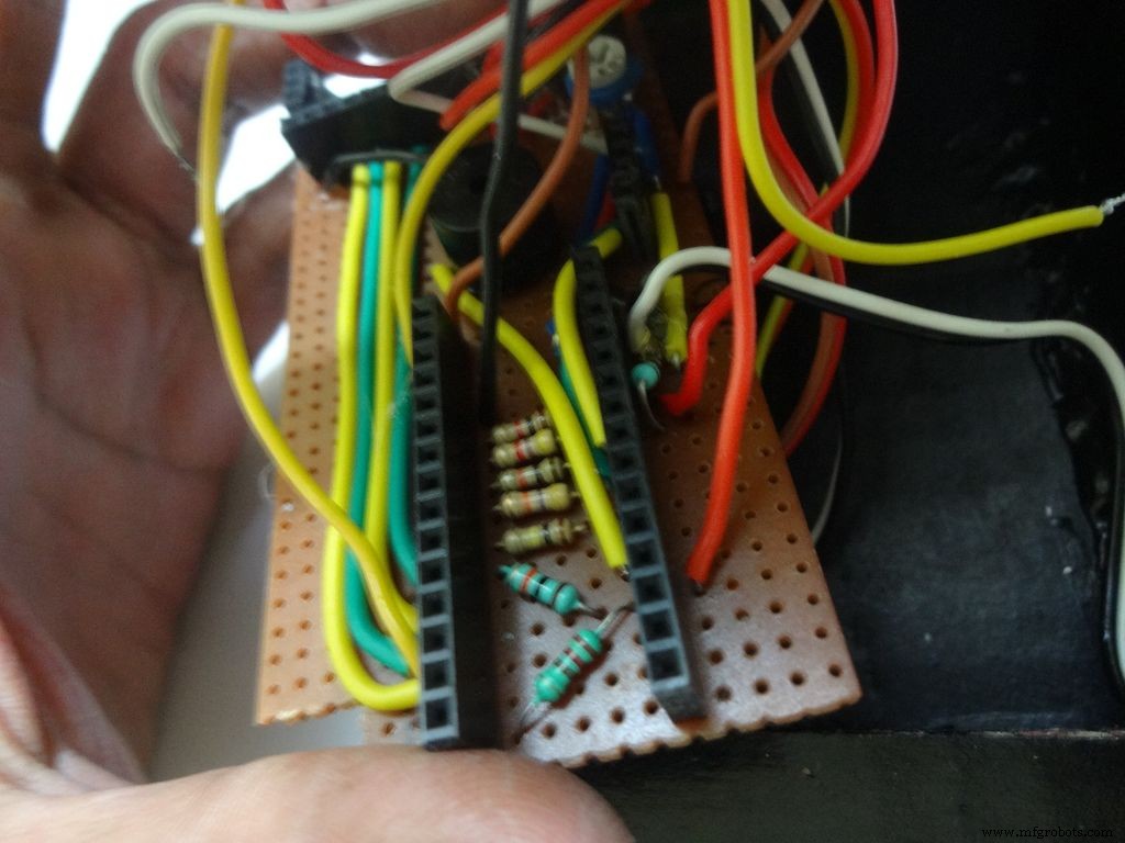 <図>
<図> 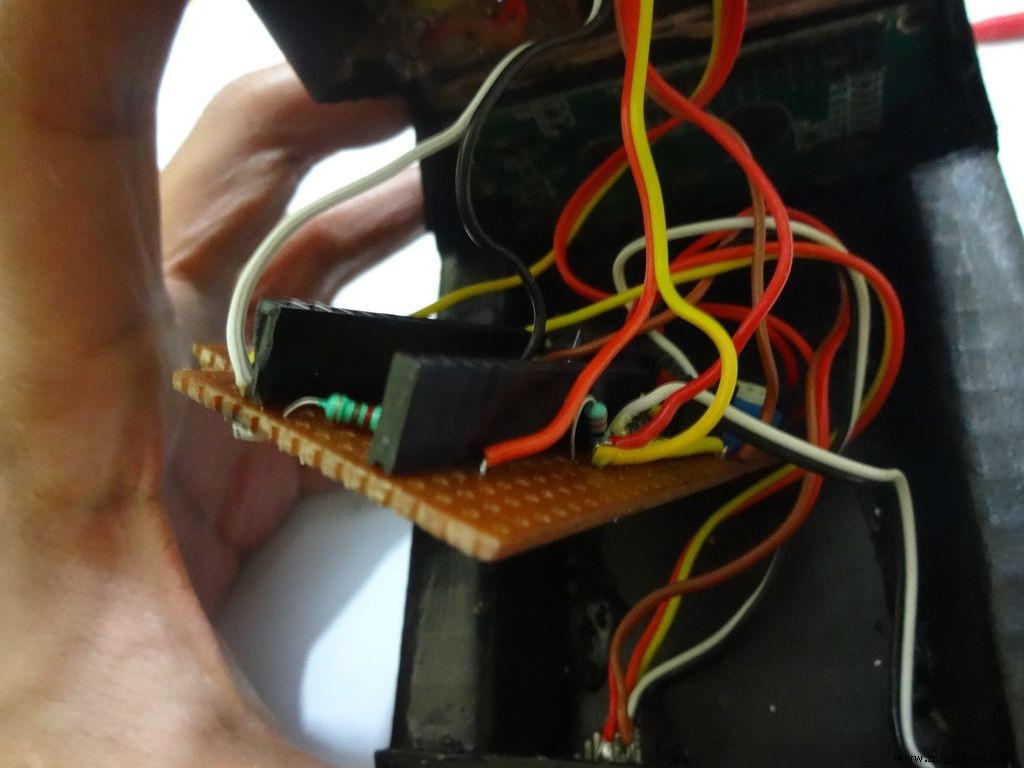
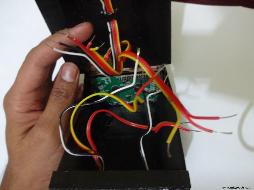
Make sure you refer the circuit design before making any connections.
First connect the reset switch, one end to RST and one end to GND.
Then, the backlight switch. One end to +5V and other end to 'A' or Anode of the backlight LED. Also connect 'K', Cathode to GND.
Next is the RS switch, connect one end to RS and other to pin D1(TX).
And finally the Enable switch. Connect one end to 'E' or Enable and other end to pin D0(RX).
Switches
Where to?
Reset - pushbutton RST and GND Backlight - slide +5V and A RS - slide D1 (TX) and RS Enable - slide D0 (RX) and E
Note:Pins D0 and D1 are connected through switches as keeping them connected sometimes causes problems while using Serial(for debugging).
This completes the base wiring. Apply hot glue after double checking the connections.
Then connect the 3 wires of mode change button:The 10k pulldown resistor to GND. 220 Ohm resistor to pin D11 and input pin to +5V or VCC
Finally connect the 6 wires from the test slots to their appropriate places(shown in images).
Positive
Negative
Resistance Test A7 GND Capacitance Test A0 GND Diode Test A6 D12
Note:All the +5Vs and GNDs are same and hence connect to most convinient spot.
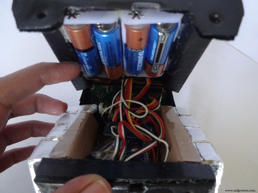
Step 31:Adding the battery case <図>
 <図>
<図> 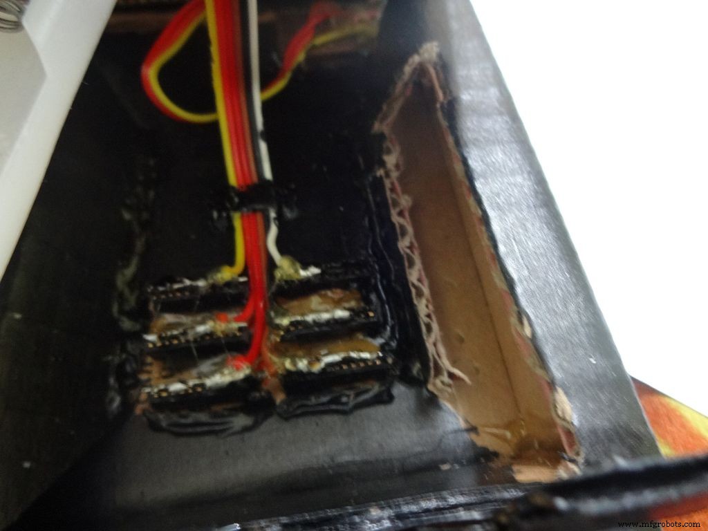 <図>
<図> 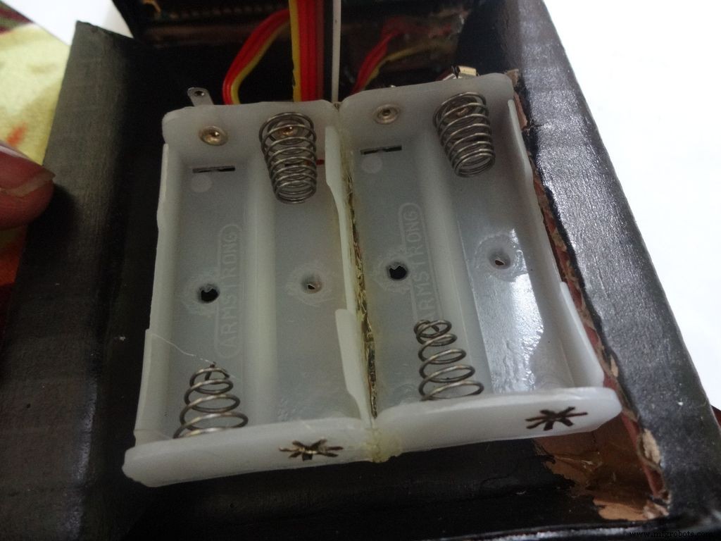 <図>
<図>  <図>
<図> 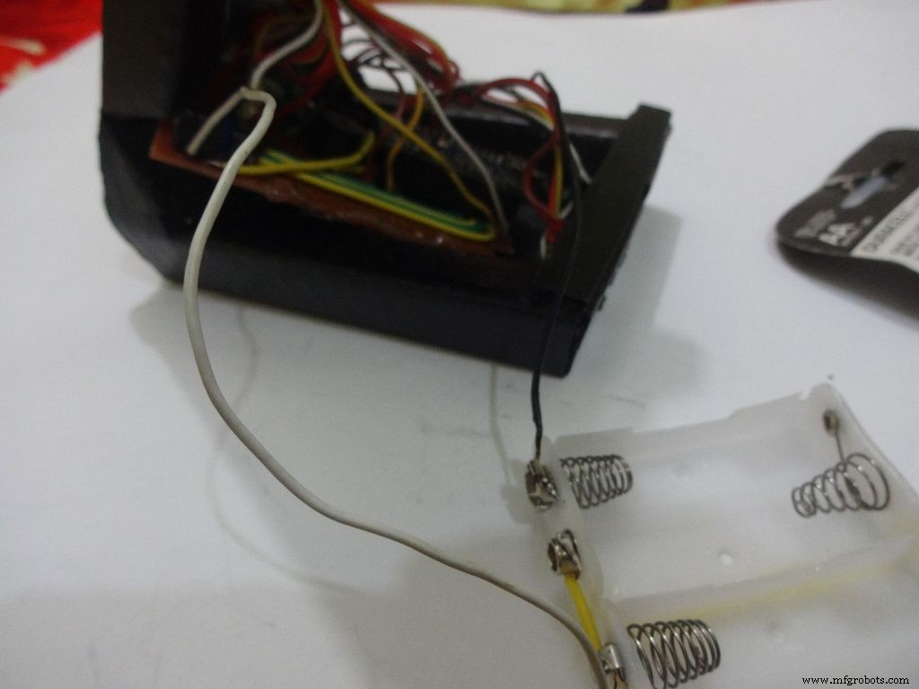 <図>
<図> 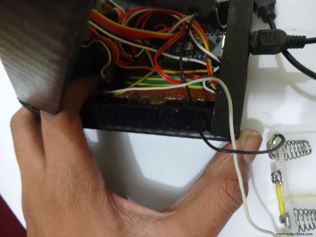 <図>
<図> 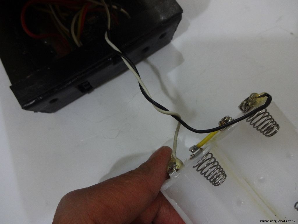 <図>
<図> 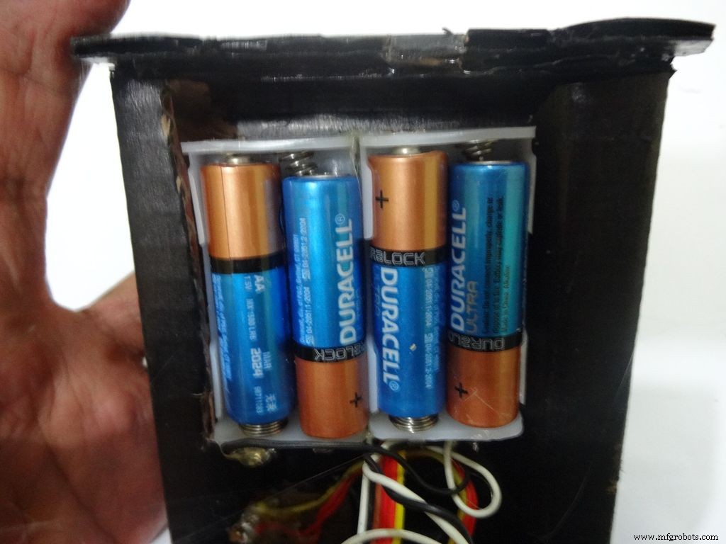 <図>
<図> 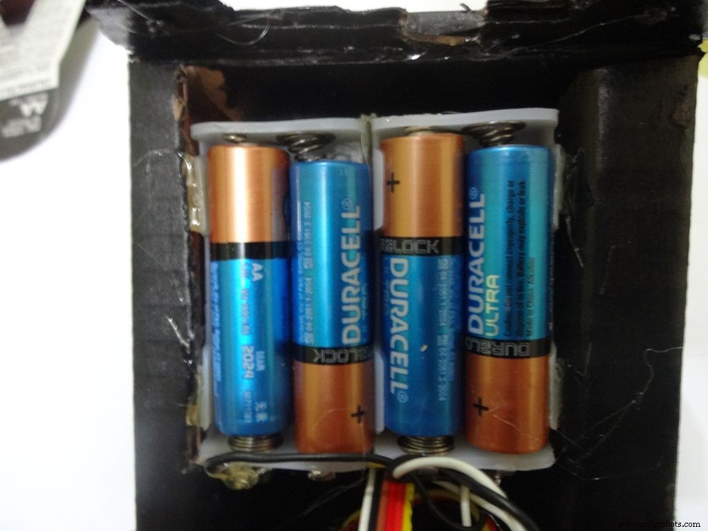
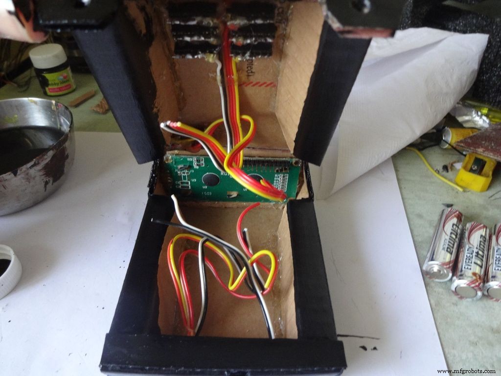
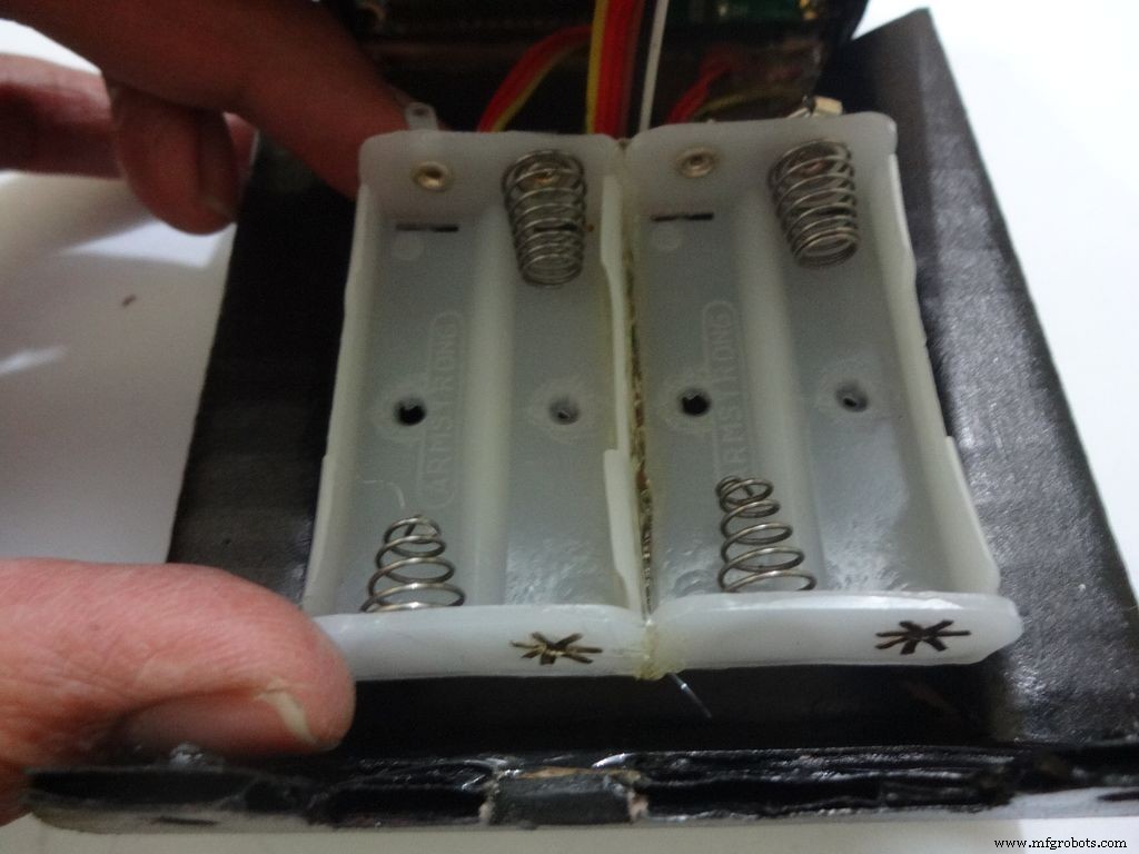
Place the battery case at the top cover, make cuts to place it inside such that the cover can be closed properly.
Solder Wires to the case, strip and tin them. Solder the positive end to the middle pin of power switch and negative end to ground.
Glue the PCB to the base after making all the connections.
Twist the wires and place them in position. Insert batteries(the case expands a bit on inserting batteries) and glue the case to the cover.
Step 32:Adding the Legs <図>
 <図>
<図> 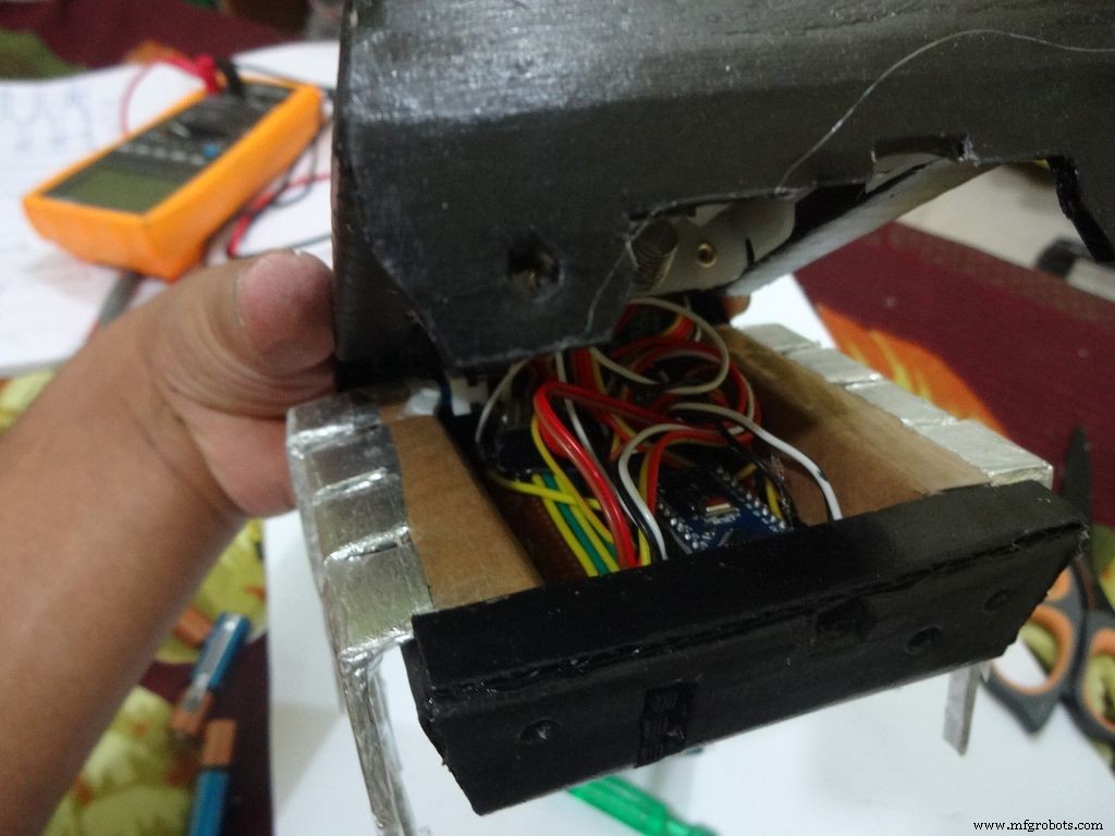 <図> <図>
 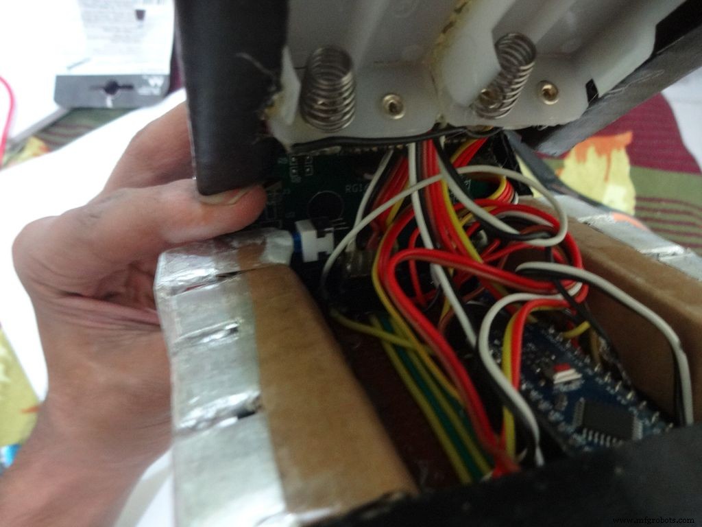 <図>
<図> 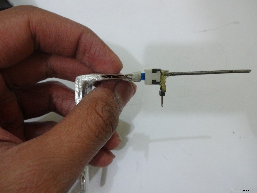 <図>
<図> 
Cut the inner part of legs so that it fits in properly. Stick it it place.
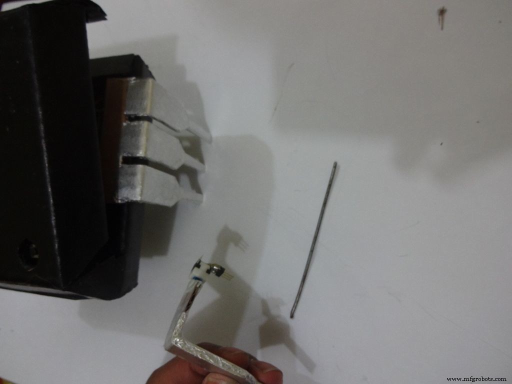
Put the power switch pin in to check if it fits in perfectly. Remove it, add a metal rod, piece of wood or anything strong of proper length that will prevent the switch from moving back. Glue it in place.
Check the switch, it should be turning on/off smoothly.
Switch on the IC and test all the functions. If its not working skip to the troubleshooting section.
Step 33:Finishing up! <図>
 <図>
<図> 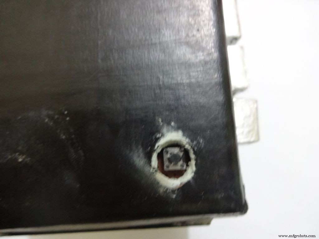 <図>
<図> 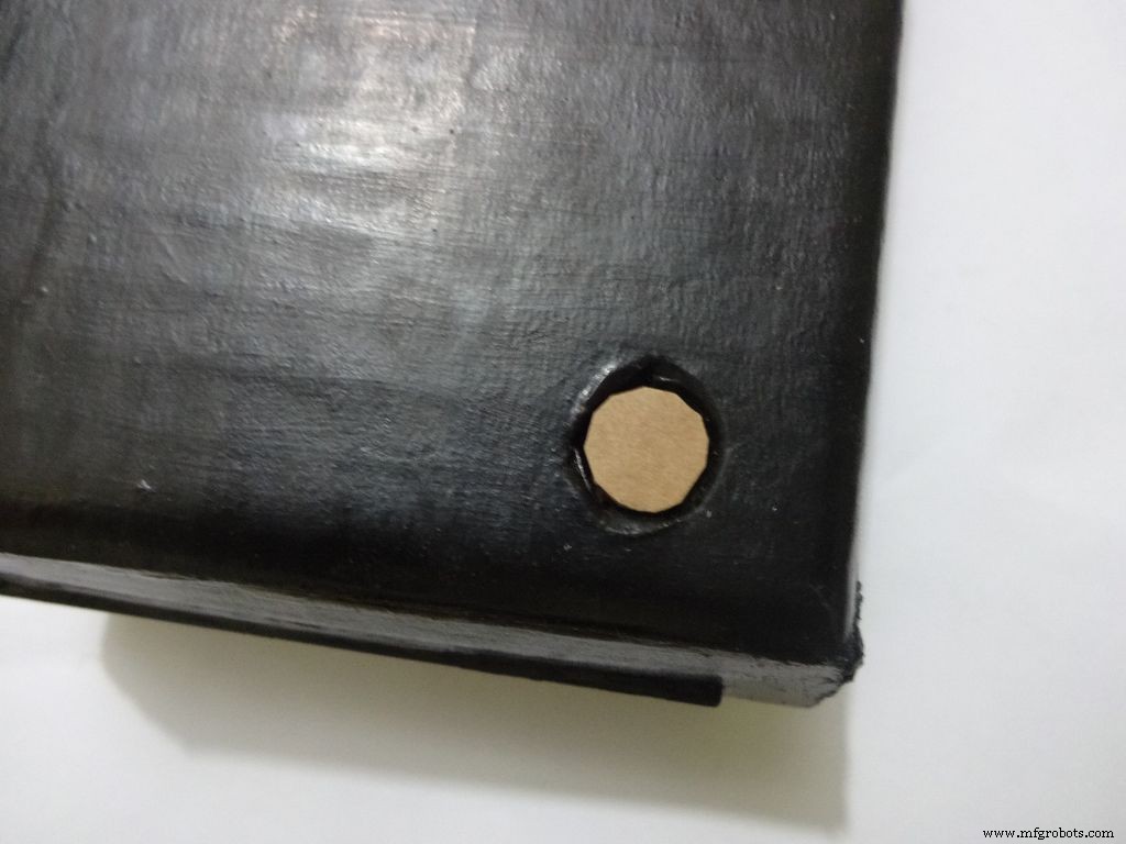 <図>
<図> 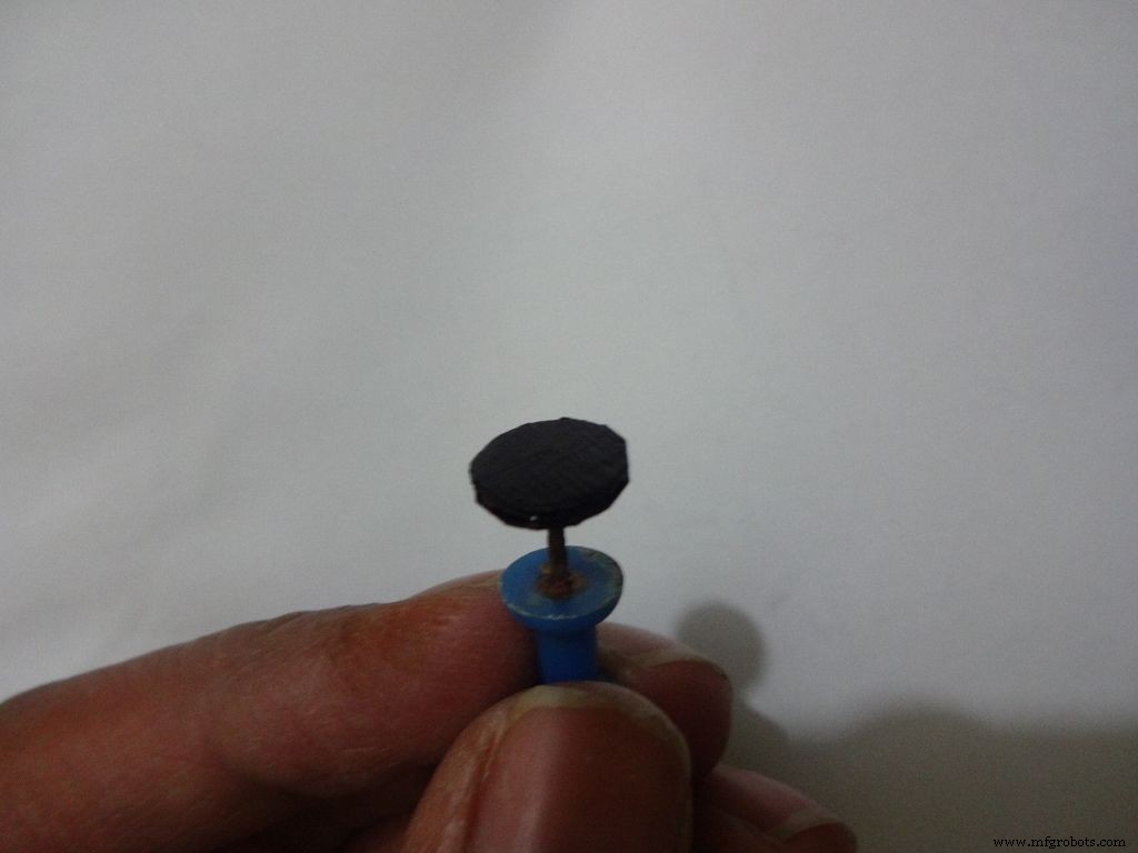 <図>
<図> 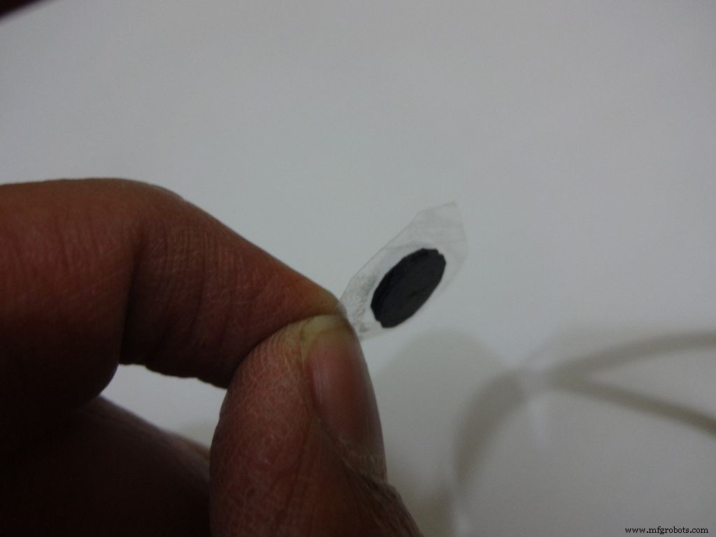 <図>
<図> 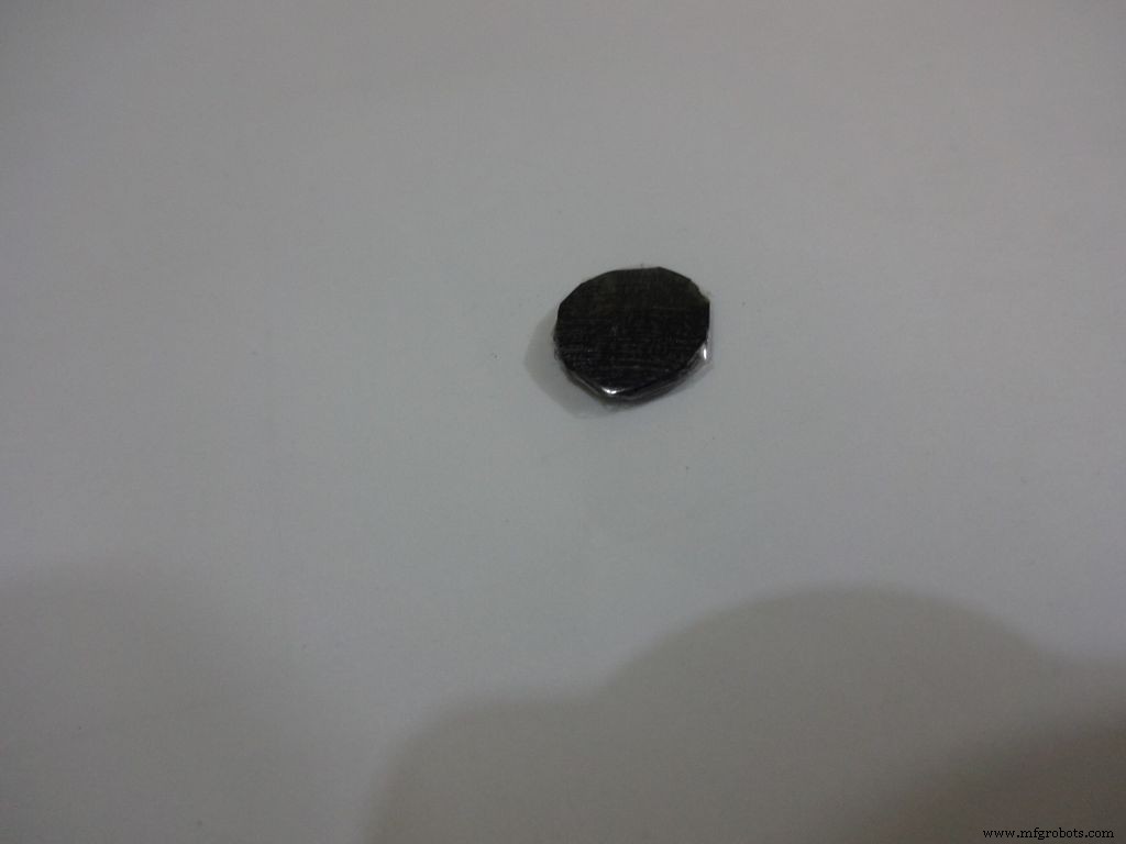 <図>
<図> 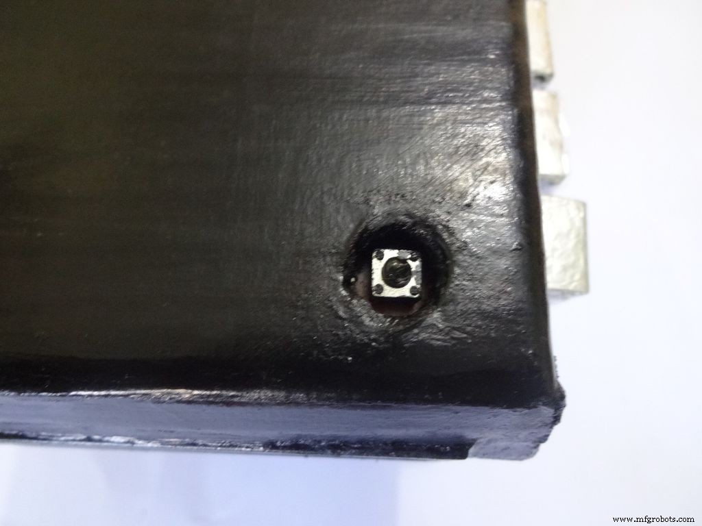 <図>
<図> 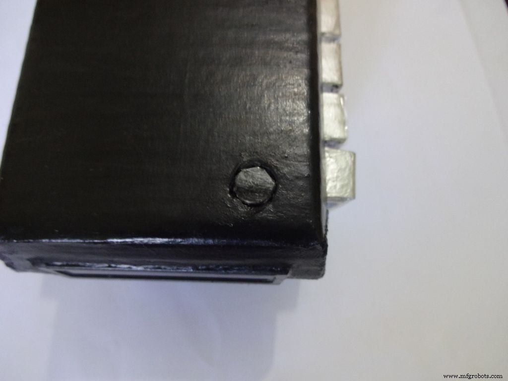 <図>
<図> 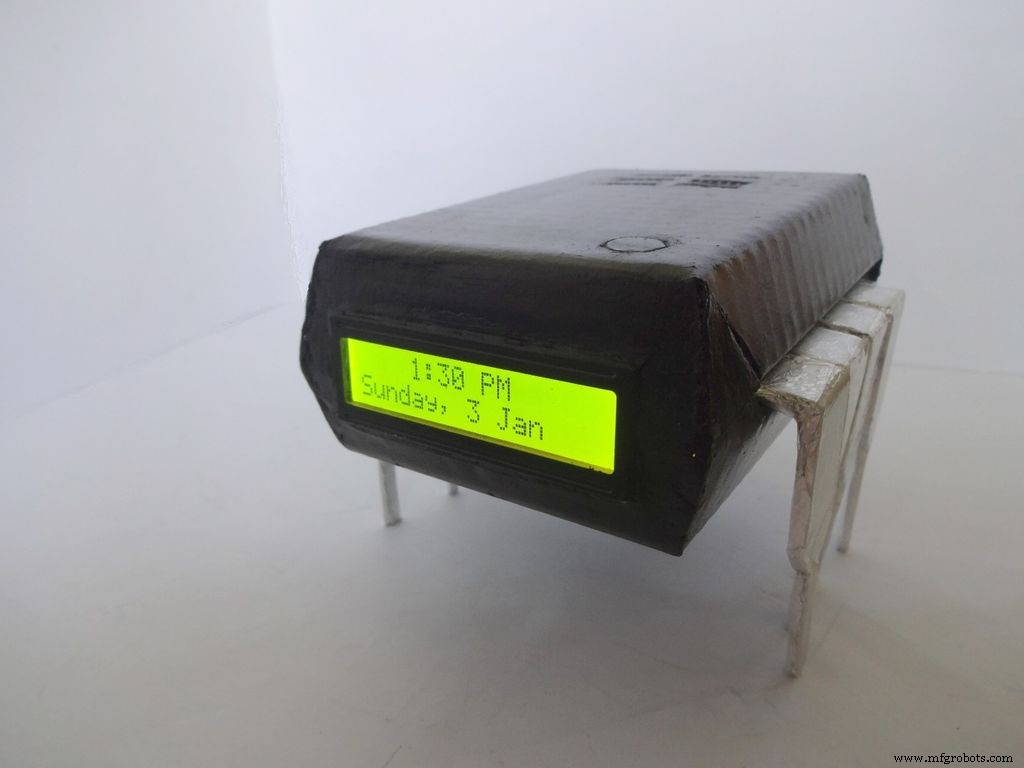
Use M-seal (or equivalent) to fill any small gaps around the testing area and the mode change button. After drying, sand it well and apply a second layer of paint.
Make the button with a small piece of cardboard, paint it black and cover it with tape(gives a shiny finish). Apply a tiny drop of glue and stick the button in place.
Step 34:Problems and Troubleshooting <図>
 <図>
<図> 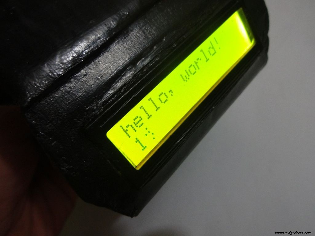 <図>
<図> 
Do everything correctly. This is the most boring most of any project and you dont wanna get here just because you soldered the wrong pins!
- Recheck every soldered joint and ensure that it isnt touching the adjacent one. Use the multimeter continuity test for help.
- After cutting component/jumper leads make sure the cut lead doesnt fall underneath the PCB. This may lead to unwanted shorting soldered joints.
- Write down anything you need to remember in a book, don't trust your memory.
- If LCD is not displaying, make sure the contrast is adjusted properly. Also make sure the pin0 and 1 switches are turned ON. Check all the pin connections from LCD to Arduino with continuity test. Use breadboard jumpers wherever your mutimeter cant reach.
- Upload the hello world LCD program to see if the problem is in the code.
- If a particular function is not working, check its connections and tally it with the code.
- And most importantly, keep your curious pets with their evil minds away from your workspace! :p
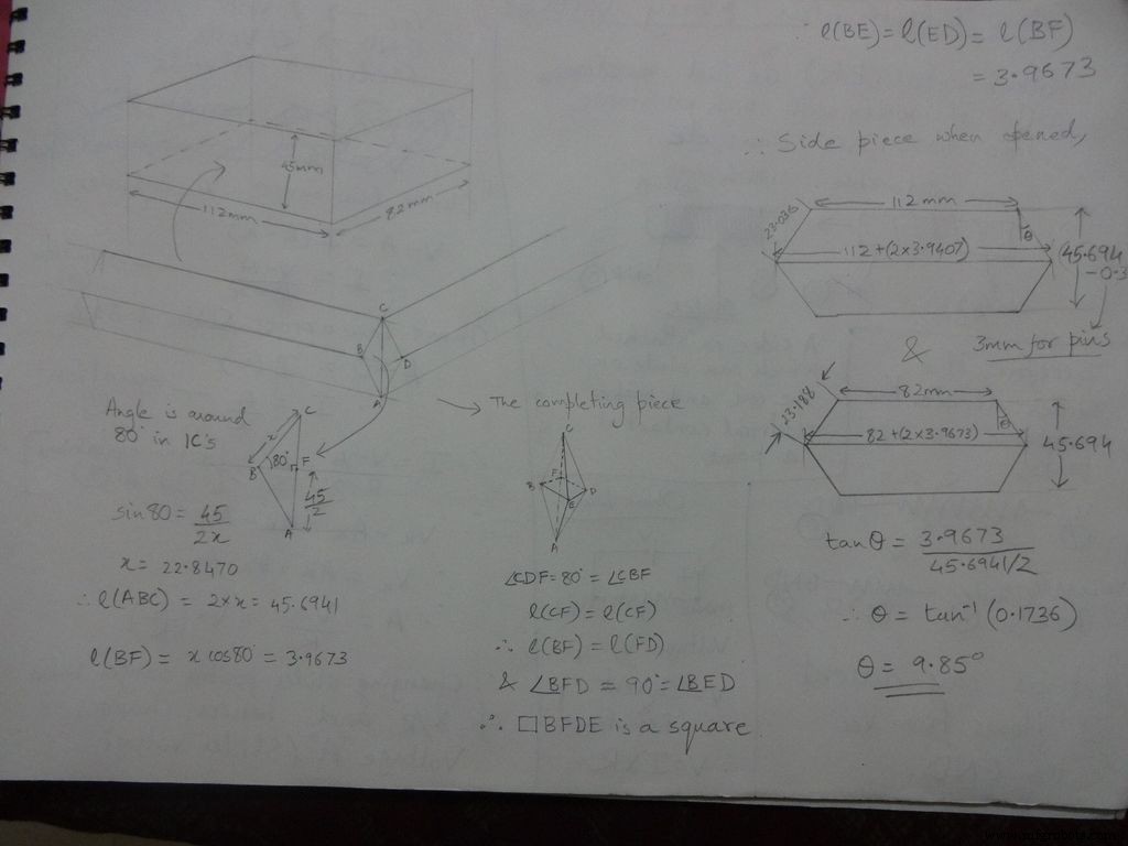
Step 35:Things I did, some mistakes I made <図>
 <図>
<図> 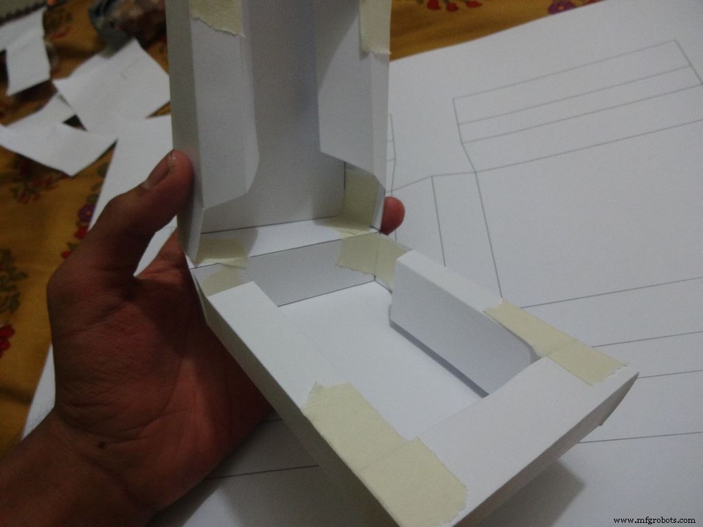 <図>
<図>  <図>
<図> 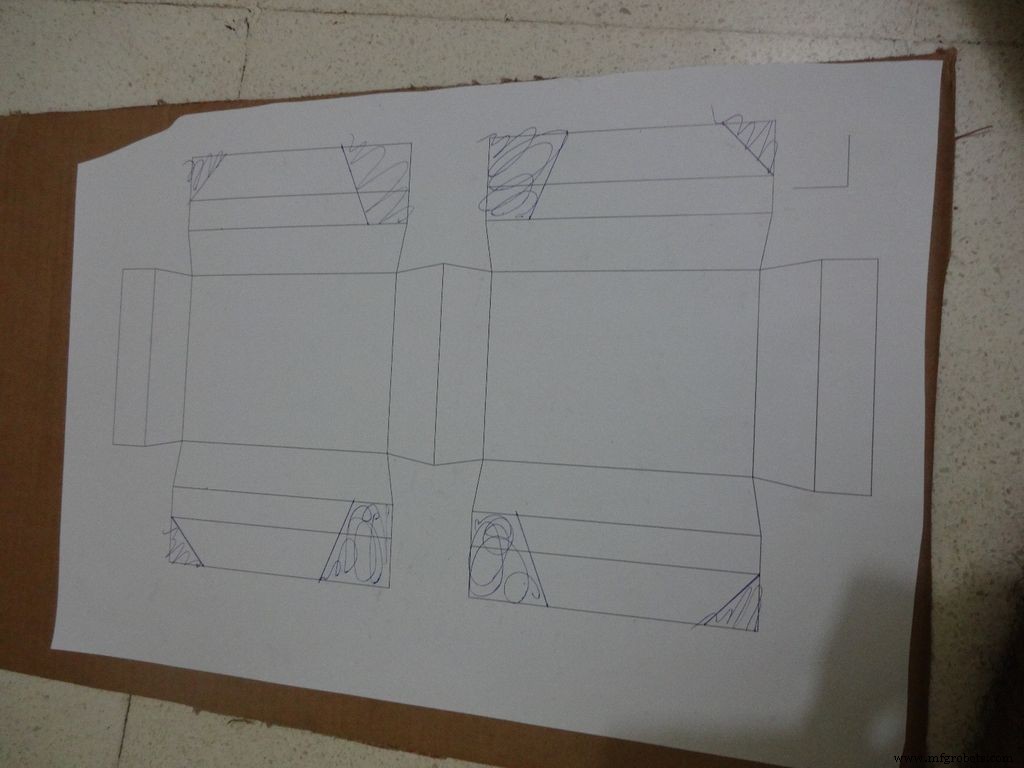 <図>
<図> 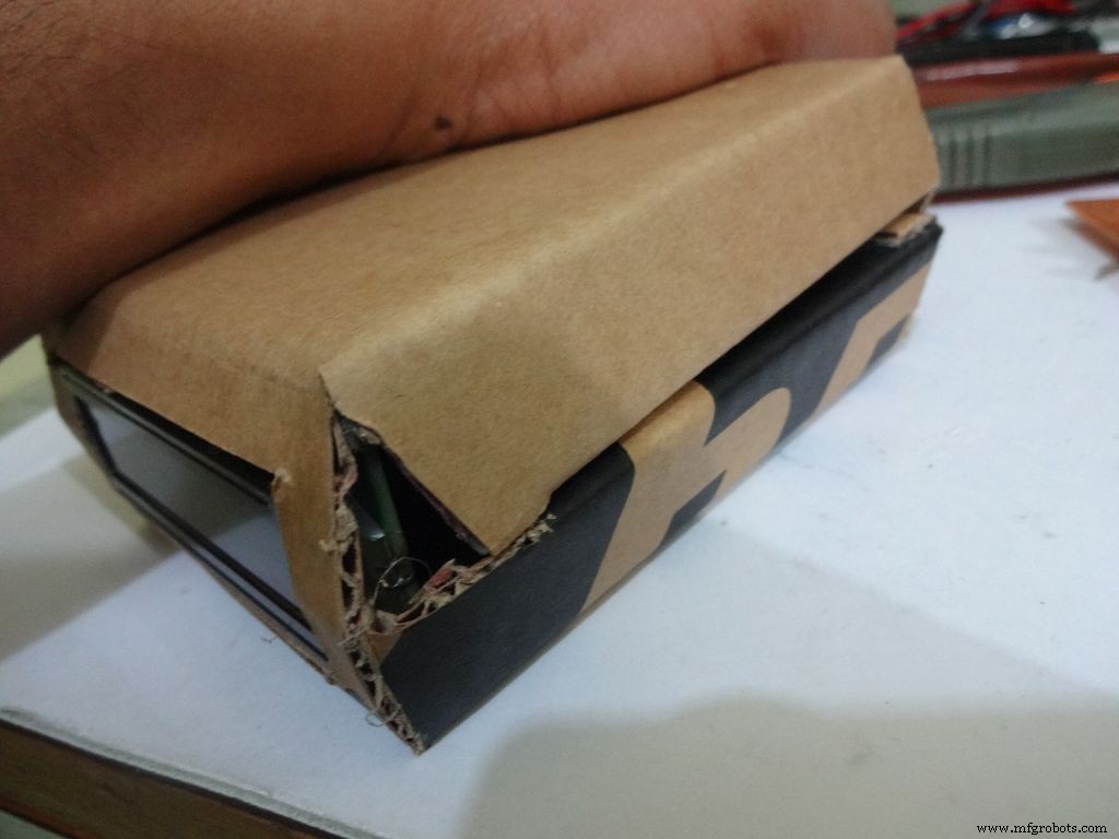 <図>
<図> 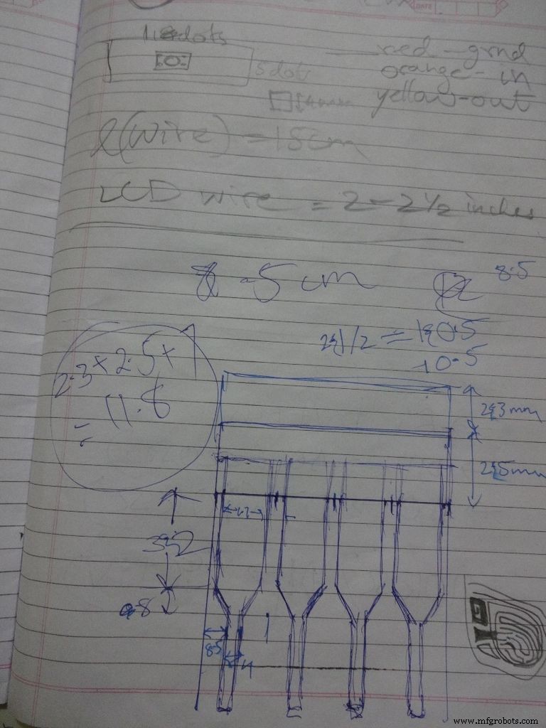 <図>
<図> 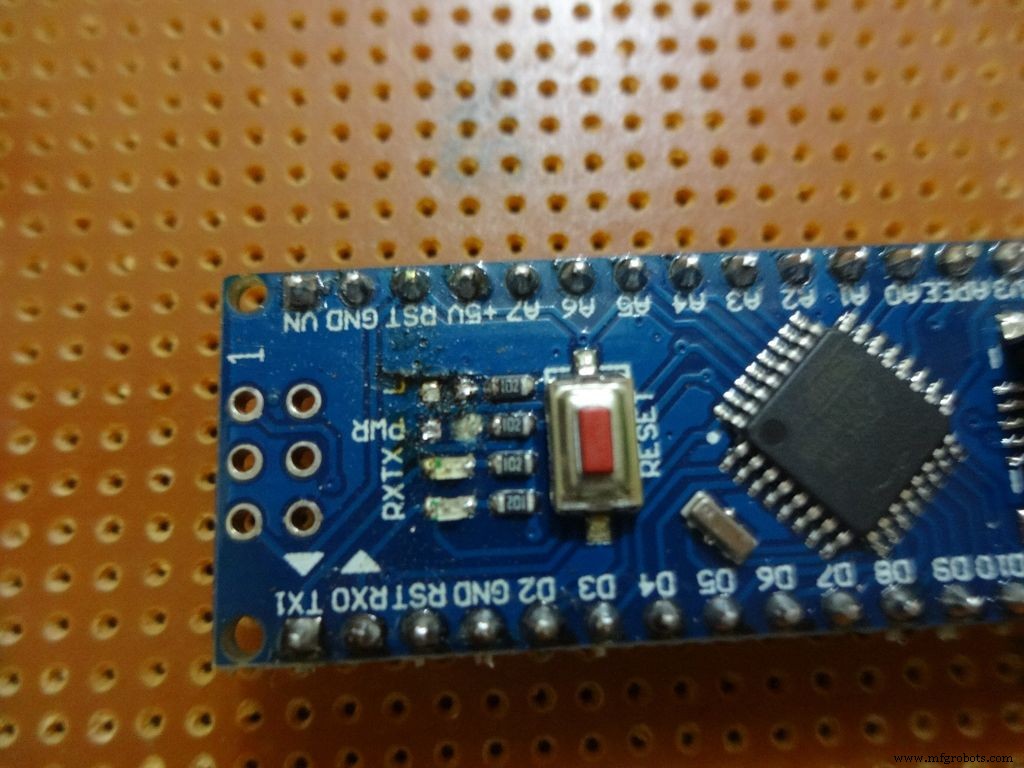 <図>
<図> 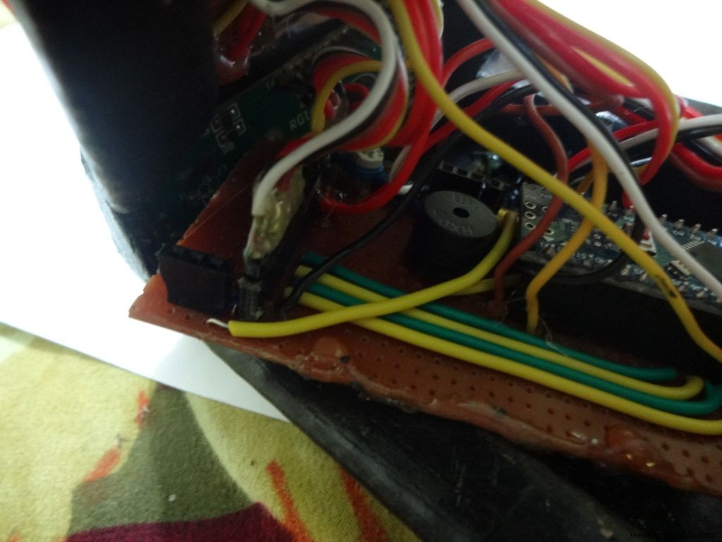 <図>
<図> 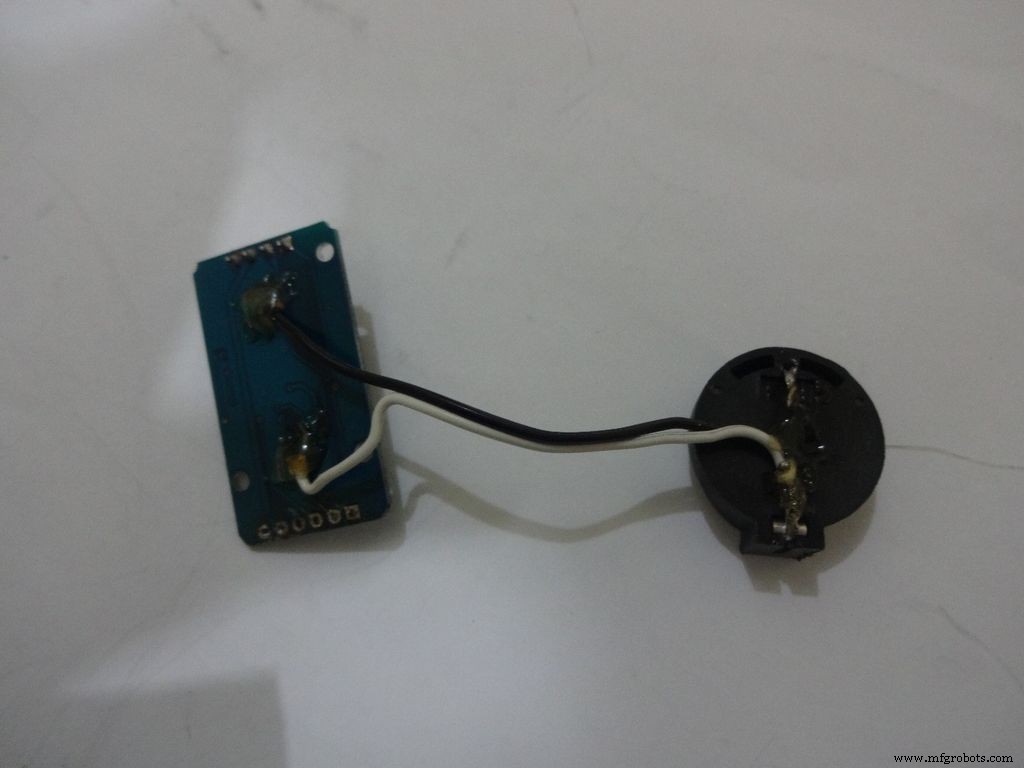
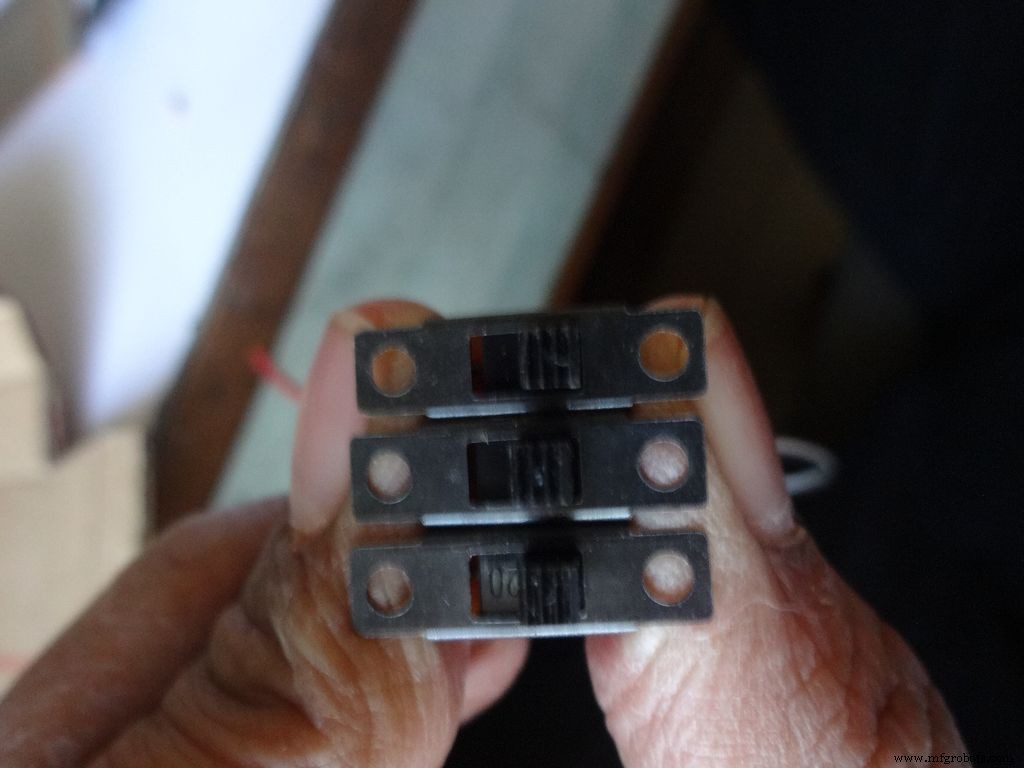
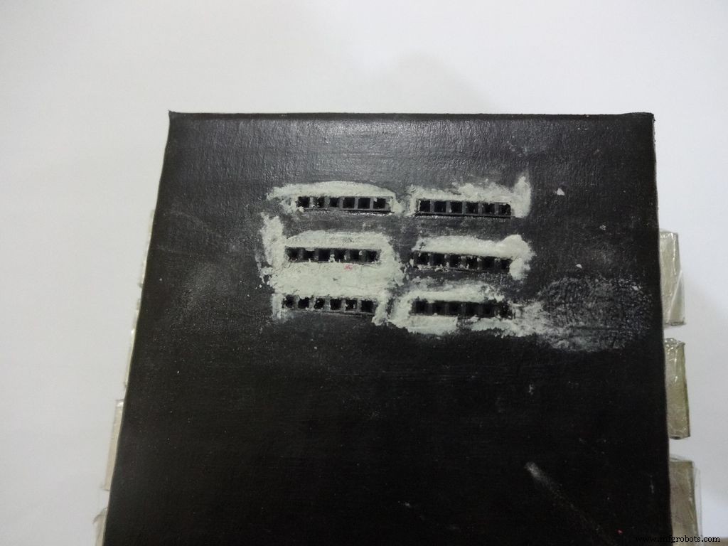
While testing the various circuits and when I had the rough idea of what I want to make, I decided to go with the IC design. I measured actual ICs, took ratios of their lengths, got the angle with some trignometry to be around 80 degrees. Then I decided the inner box length and breadth and built upon it(shown in image). Once the layout was planned, I initially started to draw it accurately on a large size paper. After a bit of a struggle of drawing accurate lines, I realised that this kind of work should be done on a computer! So I learnt CAD basics and succesfully made the layout on it. :) But this layout didnt work out and I had to redo the entire cutting and making of the case.(See images)
While removing the LEDs on the Arduino Nano I used excess pressure to remove a stubborn LED, and ended up removing a PCB pad. Always desolder without forcing/applying pressure on the joints, the pads are delicate and easily come off if you dont stay calm.
When all the solder joints were made and project was about to get finished, in excitement and eagerness, I glued the PCB inside the case before adding the battery case. Had to re-melt the hot glue with a soldering iron (carefully not to melt any wire insulation) and remove the PCB out to solder the battery case wires in. The soldering iron can be cleaned afterwards.
The RTC module battery was coming in way of the batteries while closing and so I separated the battery holder(Warning:desolder only with the battery removed) and added extension wires so that the battery can be placed at the sides where there is space.
All the Layout PDFs, CAD Files and the Main code can be downloaded here:Google Drive
コード
- コードスニペット#1
- コードスニペット#2
- コードスニペット#3
- コードスニペット#4
コードスニペット#1 プレーンテキスト
//Analog pin used to find resistanceint Apin=7;//values of r1 to r5float r1=1000;float r2=4700;float r3=10000;float r4=47000;float r5=100000;//pins of r1 to r5int r1_pin=2;int r2_pin=3;int r3_pin=4;int r4_pin=5;int r5_pin=6;float reading=0; //アナログピンから読み取り、herefloat R =0に保存します。 //不明を計算してhereStringfinalRに格納します; // unitsintcasenoとともに表示される最終値; //for debugging, stores the case number // we divide the entire range into cases and assign each a number, // total 5 cases // case1 :less than 2850 // case2 :2850 to 7350 // case3 :7350 to 28500 // case4 :28500 to 73500 // case5 :more than 73500#include// needed for converting float to string, //has the String(float,n) function. Explained below.void setup() { Serial.begin(9600);}void loop() { //first we find unknown resistance using 1kOhm resistor //Therefore, disable R2, R3, R4 and R5 digitalWrite(r2_pin, LOW); //turn each pin to LOW before setting it as INPUT pinMode(r2_pin, INPUT); // turning it to INPUT when its HIGH enables the // internal pullup resistor digitalWrite(r3_pin, LOW); pinMode(r3_pin、INPUT); digitalWrite(r4_pin、LOW); pinMode(r4_pin、INPUT); digitalWrite(r5_pin、LOW); pinMode(r5_pin、INPUT); pinMode(r1_pin、OUTPUT); digitalWrite(r1_pin、HIGH); //read and calculate resistance reading=analogRead(Apin); R =(reading * r1)/(1023-reading); // if value <2850, finalR =value(using 1kOhm) if(R<2850){ caseno=1; if(R<1000){ //if value less than 1000 use "Ohm" not "kOhm" finalR =String(R,2) + "Ohm"; //String(float,n) Converting float to string //with n digits after decimal // attach "Ohm" after value to the string, //'+' joins two strings here } else{ //use "kOhm R=R/1000; finalR =String(R,2) + "kOhm"; } } //if value between 2850 and 7350 , use value obtained by 4.7kOhm else if(R>=2850 &&R<7350){ caseno=2; digitalWrite(r1_pin, LOW); //Enable only 4.7kOhm pinMode(r1_pin, INPUT); digitalWrite(r3_pin, LOW); pinMode(r3_pin, INPUT); digitalWrite(r4_pin, LOW); pinMode(r4_pin, INPUT); digitalWrite(r5_pin, LOW); pinMode(r5_pin, INPUT); pinMode(r2_pin, OUTPUT); digitalWrite(r2_pin, HIGH); reading=analogRead(Apin); R=(reading*r2)/(1023-reading)/1000; finalR =String(R,2) + "kOhm"; } //if value between 7350 and 28500, use value obtained by 10kOhm else if(R>=7350 &&R<28500){ caseno=3; digitalWrite(r1_pin, LOW); pinMode(r1_pin、INPUT); digitalWrite(r2_pin、LOW); pinMode(r2_pin、INPUT); digitalWrite(r4_pin、LOW); pinMode(r4_pin、INPUT); digitalWrite(r5_pin、LOW); pinMode(r5_pin、INPUT); pinMode(r3_pin, OUTPUT); digitalWrite(r3_pin、HIGH); reading =analogRead(Apin); R =(reading * r3)/(1023-reading)/ 1000; finalR =String(R、2)+ "kOhm"; } //if value between 28500 and 73500, use value obtained by 47kOhm else if(R>=28500 &&R<73500){ caseno=4; digitalWrite(r1_pin、LOW); pinMode(r1_pin、INPUT); digitalWrite(r2_pin、LOW); pinMode(r2_pin、INPUT); digitalWrite(r3_pin、LOW); pinMode(r3_pin、INPUT); digitalWrite(r5_pin、LOW); pinMode(r5_pin、INPUT); pinMode(r4_pin、OUTPUT); digitalWrite(r4_pin、HIGH); reading =analogRead(Apin); R =(reading * r4)/(1023-reading)/ 1000; finalR =String(R、2)+ "kOhm"; } //if value more than 73500, use value obtained by 100kOhm else if(R>=73500){ caseno=5; digitalWrite(r1_pin、LOW); pinMode(r1_pin、INPUT); digitalWrite(r2_pin、LOW); pinMode(r2_pin、INPUT); digitalWrite(r3_pin、LOW); pinMode(r3_pin、INPUT); digitalWrite(r4_pin、LOW); pinMode(r4_pin、INPUT); pinMode(r5_pin、OUTPUT); digitalWrite(r5_pin、HIGH); reading =analogRead(Apin); R =(reading * r5)/(1023-reading)/ 1000; finalR =String(R、2)+ "kOhm"; } Serial.println(finalR); //printing the final string with units Serial.println(" "); delay(1000); }
コードスニペット#2 プレーンテキスト
/* RCTiming_capacitance_meter * code concept taken from Paul Badger 2008 * * The capacitor's voltage at one time constant is defined as * 63.2% of the charging voltage. * i.e, A Capacitor is filled to 63.2% of its total capacity in * 1 Time Constant */ int analogPin=0; //コンデンサ電圧を測定するためのアナログピンintchargePin =7; // pin to charge the capacitor - connected to // one end of the charging resistor int dischargePin=12; // pin to discharge the capacitor, // same used for diode test(checkPin1) float resistorValue=10000.0; // We use 10kOhm resistor unsigned long startTime; unsigned longlapsedTime;フロートマイクロファラッド; // floating point variable to preserve precision float nanoFarads;void setup(){ pinMode(chargePin, OUTPUT); // set chargePin to output digitalWrite(chargePin, LOW); Serial.begin(9600); // initialize serial transmission for debugging}void loop(){ digitalWrite(chargePin, HIGH); // set chargePin HIGH and capacitor charging startTime =millis(); while(analogRead(analogPin) <648){ // just wait and do nothing till 648 // 647 is 63.2% of 1023, // which corresponds to full-scale voltage } elapsedTime=millis() - startTime; // convert milliseconds to seconds ( 10^-3 ) // and Farads to microFarads ( 10^6 ), net 10^3 (1000) microFarads =((float)elapsedTime / resistorValue) * 1000; // (float) converts "unsigned long" elapsed time to float Serial.print(elapsedTime); // print the value to serial port Serial.print(" mS "); // print units if (microFarads> 1){ Serial.print((long)microFarads); // print the value to serial port Serial.println(" microFarads"); // print units } else { // if value is smaller than one microFarad, convert to nanoFarads (10^-9 Farad). nanoFarads =microFarads * 1000.0; // multiply by 1000 to convert to nanoFarads (10^-9 Farads) Serial.print((long)nanoFarads); // print the value to serial port Serial.println(" nanoFarads"); // print units } /* dicharge the capacitor */ digitalWrite(chargePin, LOW); // set charge pin to LOW pinMode(dischargePin, OUTPUT); // set discharge pin to output digitalWrite(dischargePin, LOW); // set discharge pin LOW while(analogRead(analogPin)> 0){ // wait until capacitor is completely discharged } pinMode(dischargePin, INPUT); // set discharge pin back to input} コードスニペット#3 プレーンテキスト
String state ="null"; //prints "null" for reverse bias or nothing connectedint checkPin1 =12;int checkPin2 =6;void setup() { Serial.begin(9600);}void loop() {pinMode(checkPin1, OUTPUT); digitalWrite(checkPin1、LOW); //ピン11はローに設定されます//アナログ読み取りは通常10k抵抗によってプルアップされるため、ヌル読み取りは1023 //フォワードバイアスでは、アナログピンはLOWであるcheckPin1に接続されます。 So reading less than 1023//Practically a small current flows in reverse bias as well, so we take 700 to differentiate if(analogRead(checkPin2)<700){ state="forward"; } Serial.println(state); Serial.println(analogRead(checkPin2)); state ="null"; delay(500);} コードスニペット#4 プレーンテキスト
// Date and time functions using a DS1307 RTC connected via I2C and Wire lib#include #include RTC_DS1307 rtc;//creating "rtc" object of RTC_DS1307, objects are used to access functions //more on objects and classes:https://www.youtube.com/watch?v=ABRP_5RYhqUchar daysOfTheWeek[7][12] ={"Sunday", "Monday", "Tuesday", "Wednesday", "Thursday", "Friday", "Saturday"};void setup () { Serial.begin(9600); rtc.begin(); // following line sets the RTC to the date &time this sketch was compiled // rtc.adjust(DateTime(F(__DATE__), F(__TIME__))); // This line sets the RTC with an explicit date &time, for example to set // January 21, 2014 at 3am you would call:// rtc.adjust(DateTime(2014, 1, 21, 3, 0, 0));}void loop () { DateTime now =rtc.now(); Serial.print(now.year()); Serial.print( '/'); Serial.print(now.month()); Serial.print( '/'); Serial.print(now.day()); Serial.print(" ("); Serial.print(daysOfTheWeek[now.dayOfTheWeek()]); Serial.print(") "); Serial.print(now.hour()); Serial.print( ':'); Serial.print(now.minute()); Serial.print( ':'); Serial.print(now.second()); Serial.println(); Serial.println(); delay(1000);} Github
https://github.com/adafruit/RTClibhttps://github.com/adafruit/RTClib 回路図
Main_Schematic.fzz製造プロセス