


アルツハイマー病助手
コンポーネントと消耗品
>  |
| × | 1 | |||
 |
| × | 1 | |||
| × | 1 | ||||
 |
| × | 1 | |||
 |
| × | 1 | |||
 |
| × | 1 | |||
 |
| × | 1 | |||
| × | 1 | ||||
| × | 1 | ||||
| × | 1 |
必要なツールとマシン
>  |
|
アプリとオンラインサービス
>  |
| |||
 |
| |||
 |
|
このプロジェクトについて
アルツハイマー協会のウェブサイト(2017年9月に取得)から直接引用されたこれらの事実は、人や愛する人がアルツハイマー病にかかっている場合に直面しなければならない問題を誰にでも理解させるのに十分です。
メーカーである私は、これについて考え、患者とその世話人の両方を支援できるウェアラブルデバイスを構築することにしました。
このシステムは、少なくとも次のタスクを実行できる必要があります。
- 患者にタスクを実行することを思い出させるために、彼/彼女は毎日(投薬、運動など)行う必要があります
- 患者が家のどこにいるかを監視する
- 何らかの緊急事態が発生した場合に備えて、世話人に警告します
- 時刻を表示します(結局のところ、時計です!)
- 高齢の患者でも持ち運びができ、使いやすいものでなければなりません
- コストを最小限に抑える必要があります
インフィニオンのセンサーハブナノを見たとき、そのサイズが非常に小さく、BLE機能があるため、このようなプロジェクトに適しているように見えました。正確な圧力検知により、患者が転倒したかどうかを検出し、患者が家のどこにいるかを正確に知ることができます。
ベアボーンプロジェクトには次のパーツを使用します 機能する:
- インフィニオンのセンサーハブナノ
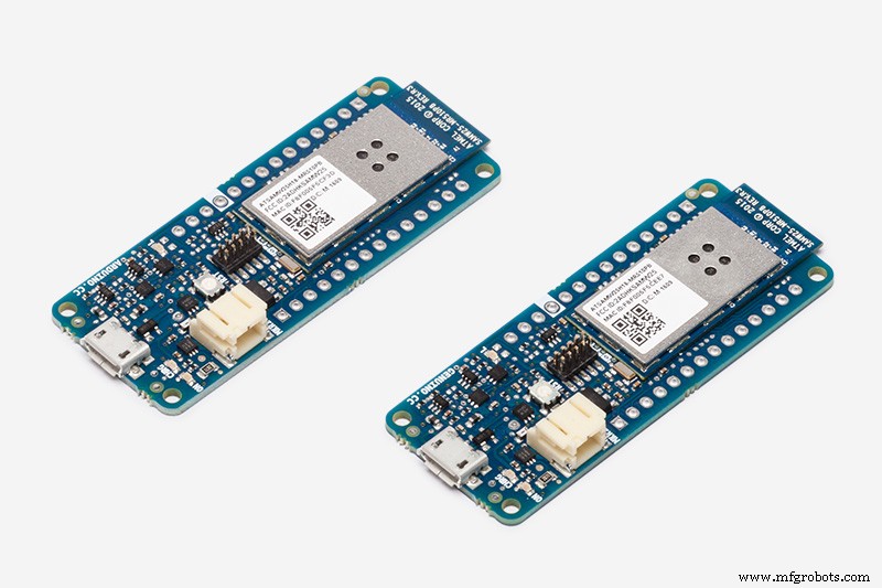
- Arduino MKR1000
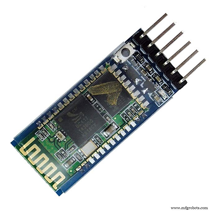
- HC-05Bluetoothモジュール
- Nokia5110ディスプレイ

「PersonalisingAlzheimer’s Assistant」セクションを読むと、「ベアボーンプロジェクト」の意味がわかります。
仕組み
このセクションでは、時計がどのように機能するかを簡単に説明し、時計を機能させるために実行する必要のある手順の概要を説明します。
インフィニオンのセンサーハブNano評価ボードにはDPS310気圧センサーが搭載されており、Bluetoothを介して評価ボードを介してデータを送信します。気圧、高度、気温の値は、インフィニオンのAndroidアプリ(ここからダウンロード)およびSES2G評価ソフトウェアで表示できます。ユーザーは、独自の要件に基づいて、インフィニオンが提供するライブラリを使用してAndroid用のアプリケーションを構築することもできます。
<図>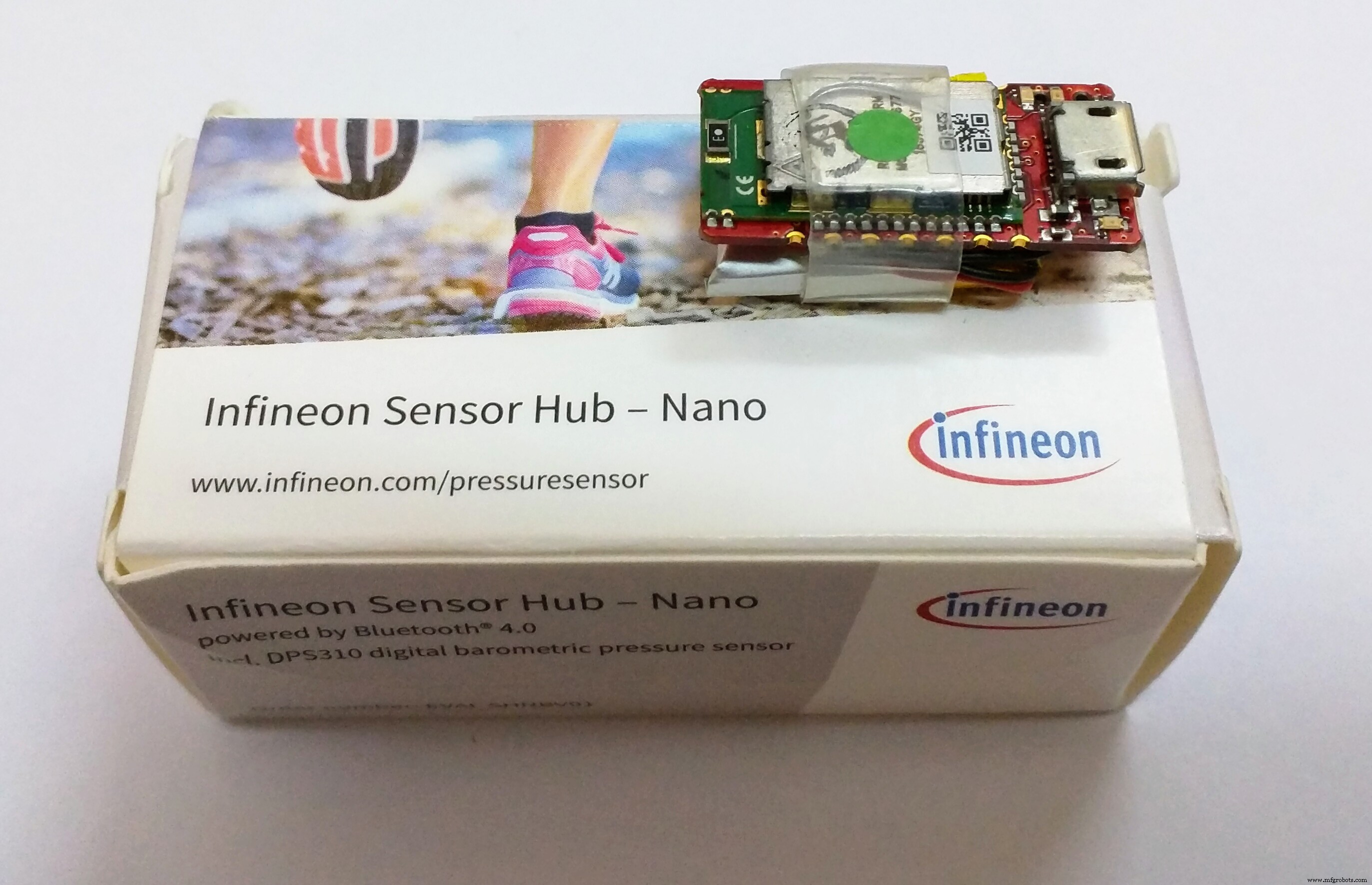
Sensor Hub Nanoの詳細については、こちらをご覧ください。
<図>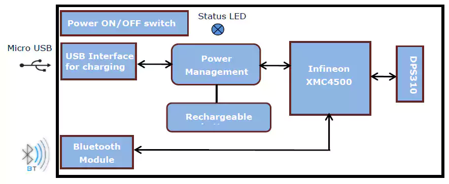
しかし、私はアルツハイマー病のアシスタントが間にAndroidフォンがなくても機能することを望んでいます。それは、それ自体で機能するだけでなく、スマートフォンに接続してセンサーデータを表示する機能を備えたウェアラブルである必要があります。そこで、フォームファクタが小さくWiFi機能を備えたArduino MKR1000ボードを使用し、何らかの方法でセンサーハブナノに接続することにしました。
これは、便利なArduinoMKR1000のピン配列です:
<図>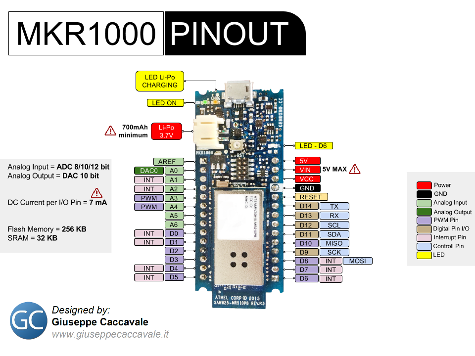
私はHC-05Bluetoothモジュールを持っていたので、ArduinoMKR1000とSensorHubNano間の接続にそれを使用する必要がありました。ただし、最初に、ロジックレベルを考慮して、HC-05をArduinoのハードウェアTxピンとRxピンに適切に接続する必要があります。私のBluetoothモジュールは3.3vで動作します。これはMKR1000と同じであるため、電圧レベルシフターは必要ありませんでした。ただし、Bluetoothモジュールが5vレベルで動作する場合は、示されているものと同様のレベルシフターを使用する必要がある場合があります。
<図>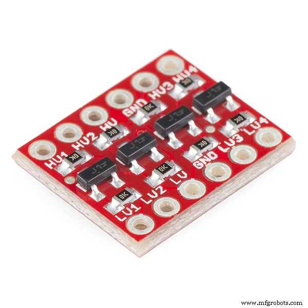
電圧レベルを一致させた後、HC-05をSensor Hub Nanoとペアリングして、それらの間のデータ通信を開始し、Sensor HubNanoがHCのBluetooth範囲に入るたびに自動的にペアリングする簡単な方法を見つける必要があります。 -05。
そのために、Bluetoothの「マスター」デバイスとして機能するようにHC-05を構成し、特定のMACアドレスとのみペアリングすることを考えました。センサーハブナノのそれ。したがって、そのように構成した後、HC-05をオンにすると、特定のMACアドレス(Sensor Hub Nanoのアドレス)を持つデバイスを検索し、自動的にペアリングして、送信と送信をユーザーに任せます。データを受信します。
これは、HC-05のATモードコマンドを使用して実行され、「Bluetoothモジュールの構成」セクションで説明されています。
注:オンラインで見つけたドキュメントを添付しました。このドキュメントには、HC-05がサポートするすべてのATコマンドが記載されているため、必要に応じて使用してください。
ペアリングされて正しく接続されると、Sensor HubNanoにコマンドを送信することはBluetooth端末のようになります。上記で指定したコマンドは、HC-05が接続されているハードウェアシリアルポートを介して文字列として出力するだけで使用できます。たとえば、これはセンサーデータのフローを開始するために送信するコマンドです:
$ start_sensor id =1 //センサーデータのフローを開始するには これが私が知っているコマンドのリストです:
  $ hello id =// Hello
 $ info id =// Info
 $ sinfo id =1 //センサー情報
 $ set_mode sid =1; md =mode; val =bg //低エネルギー
 $ set_mode sid =1; md =prs_osr; val =16 //標準モード
 $ set_mode sid =1; md =prs_mr; val =32 //高精度
 $ start_sensor id =1 //開始
 $ stop id =//停止
Sensor Hub Nanoからのセンサーデータは次の形式です:
  $ 1、t、36.9299,1154206 //温度
 $ 1、p、997.6813,1154206 //気圧
$ 1、a、130.4305,1154206 //高度 注:PeterSmithのを参照したいと思います。 ブログ投稿 Bluetoothを使用してSensorHubNanoとの通信を開始するのに役立ちました。
モジュールからデータのフローを開始できるようになったら、モジュールからデータを解析する方法が必要です。これは、私が認めなければならない、プロジェクトの最も困難な部分でした。データのフローを開始するコマンドを送信すると、Sensor Hub Nanoはデータのストリームを送信するだけで、データを受信するデバイスに任せて、そこから適切なものをすべて解析します。したがって、複雑さの異なる多くの方法を試した後(ここでは説明しません)、これは、Sensor Hub Nanoからのデータを解析するために、私が思いついた最も単純で最も効率的な方法でした。
  void getSensorValues(){
 //センサーハブNanoからSerial1ポートを介してセンサー値を取得します
 String junkVal;
 if(Serial1.available()){
 junkVal =Serial1.readStringUntil( '\ n');
 junkVal =Serial1.readStringUntil( 't');
 t =Serial1.parseFloat();
 junkVal =Serial1.readStringUntil( 'p');
 p =Serial1.parseFloat();
 junkVal =Serial1.readStringUntil( 'a');
 a =Serial1.parseFloat();
 junkVal =Serial1.readStringUntil( '\ n');
}
}
ディスプレイもArduinoに接続され、ユーザーと対話したり、メッセージを表示したり、センサーからの時間やデータを表示したりします(これについては読み進めてください)。
<図> <図>
<図> 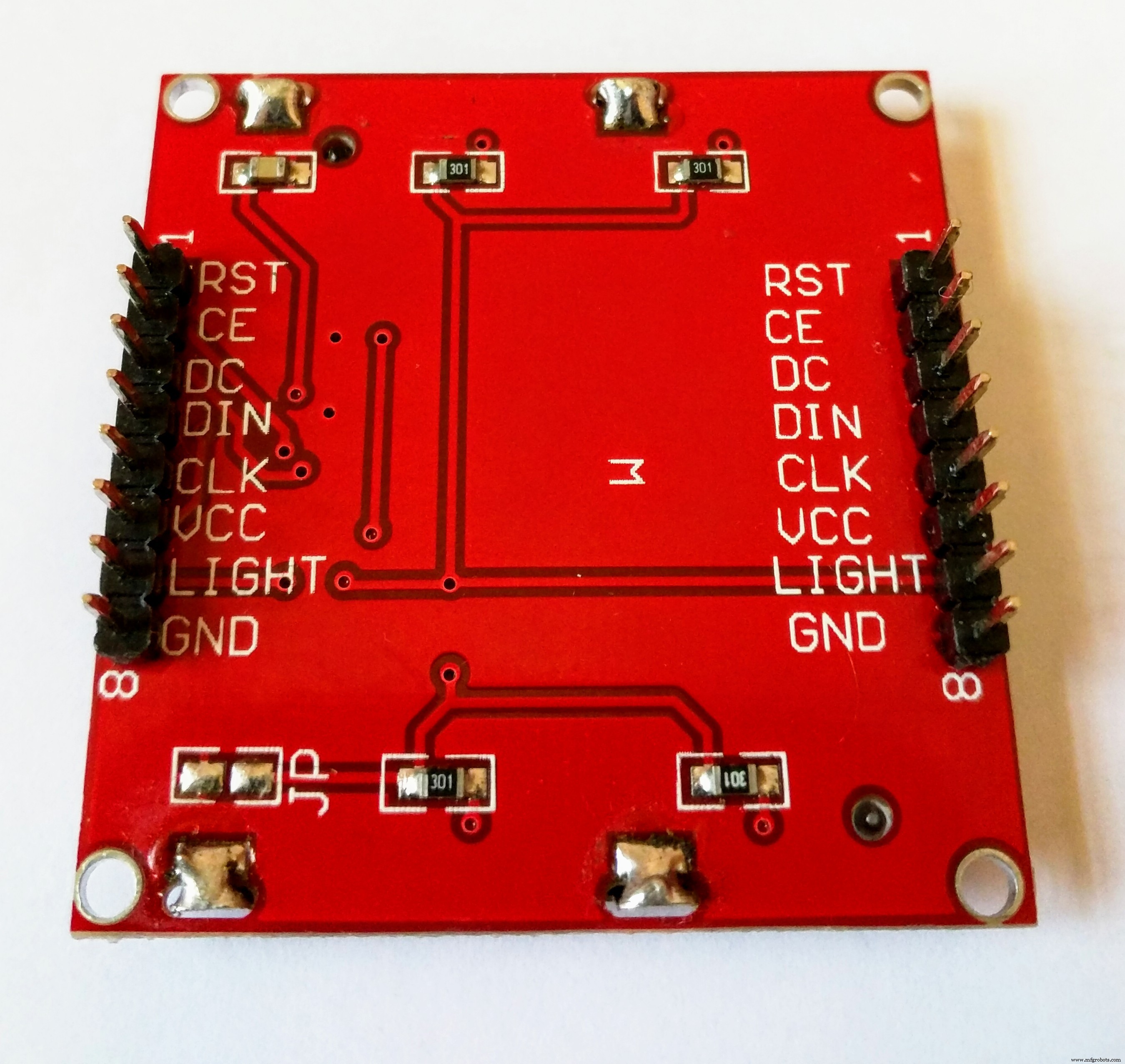
Arduino MKR1000でデータを取得すると、そのワイヤレス接続により、CayenneやBlynkなどのさまざまなIoTプラットフォームにデータを送信できます。
<図>
その美しいインターフェースと簡単なセットアップに感銘を受けたので、これにはカイエンを使用することにしました。しかし、残念ながら、MKR1000 WiFi接続にいくつかのバグがあり、ピンを選択できませんでした。カイエンヌにいる人たちはとても親切でしたが、それでも問題は解決しませんでした。したがって、最終的にBlynkを使用することにしましたが、使用法は非常に似ているため、Arduinoコードを数行変更するだけで、テストする場合、または問題が発生した場合に、BlynkからCayenneに切り替えることができます。解決しました。どちらも多かれ少なかれ同じ機能を持っているので、それはあなた自身の好みです。ただし、Cayenneの唯一の利点は、PCでもアクセスできることですが、Blynkはスマートフォンでのみ機能します。
<図>
これで、Sensor Hub Nanoからデータを受け取り、それをArduinoに取り込み、IoTプラットフォーム(これからはBlynkと言います)に転送したので、アルツハイマー病のアシスタントをパーソナライズする必要があります。あなた自身のニーズに合わせて、それは別のセクションで扱われます(落下と位置の検出についてはそこで説明されています)。
注:私はすべてのステップを詳細に文書化しようとしましたが、何かがわからない場合(Arduinoにコードをアップロードするなど)は、Arduinoにアクセスすることをお勧めします ホームページ 、しばらくの間それをよく理解してから、少なくとも基本を理解したら、これに戻ってください。
Bluetoothモジュールの構成
最初に行う必要があるのは、Sensor Hub Nano EvaluationKitのMACアドレスを取得することです。それを行うにはさまざまな方法がありますが、どのように行ったかを説明します。
Sensor Hub Nanoをスマートフォンとペアリングします:
<図>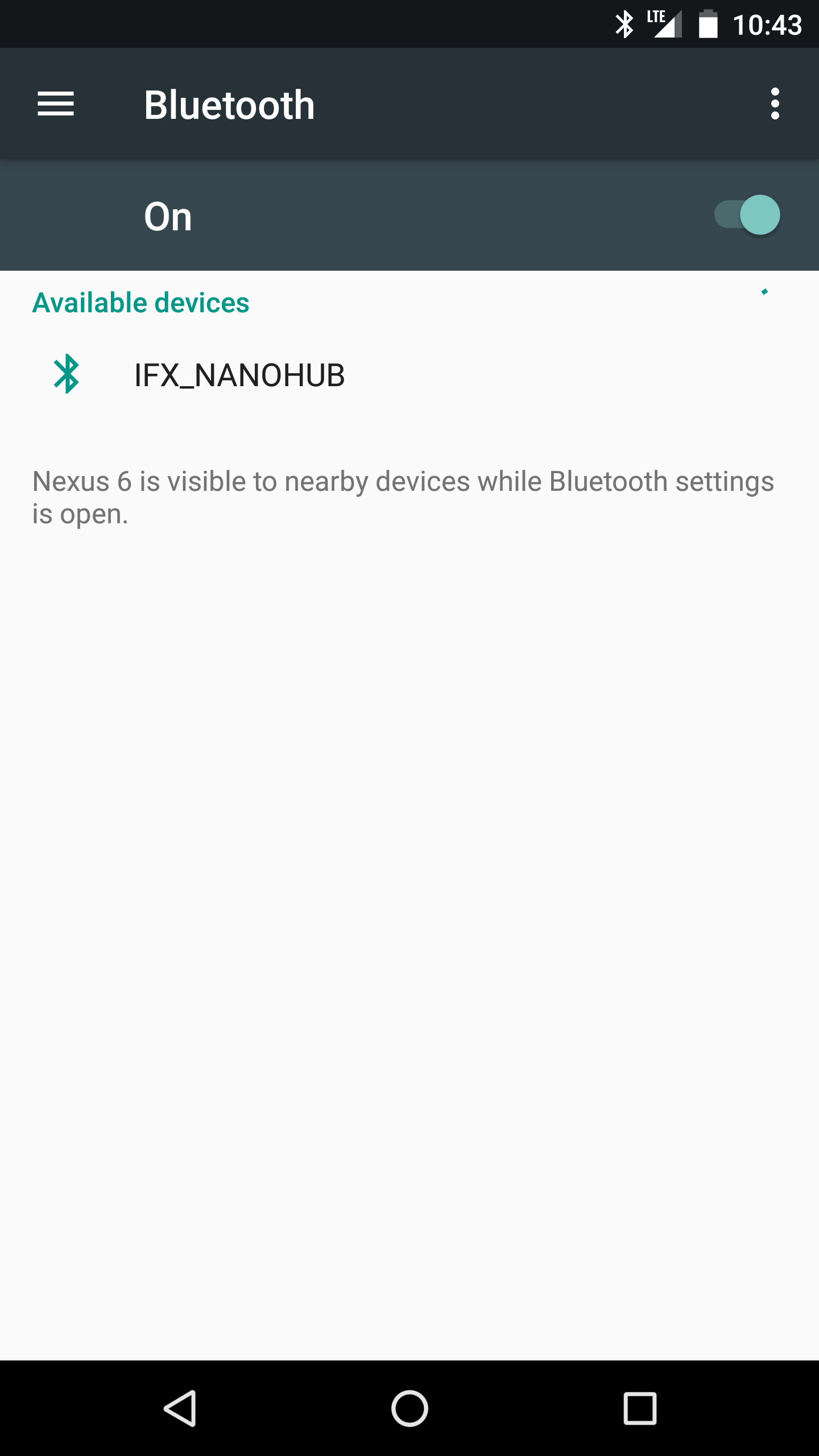 <図>
<図> 
ここからインフィニオンのセンサーハブナノ評価アプリ(Android用)をダウンロードし、センサーハブナノのスイッチを入れます。アプリを開くと、Sensor Hub Nanoが「IFX_NANOHUB」と表示され、その下にMACアドレスが表示されます。
<図>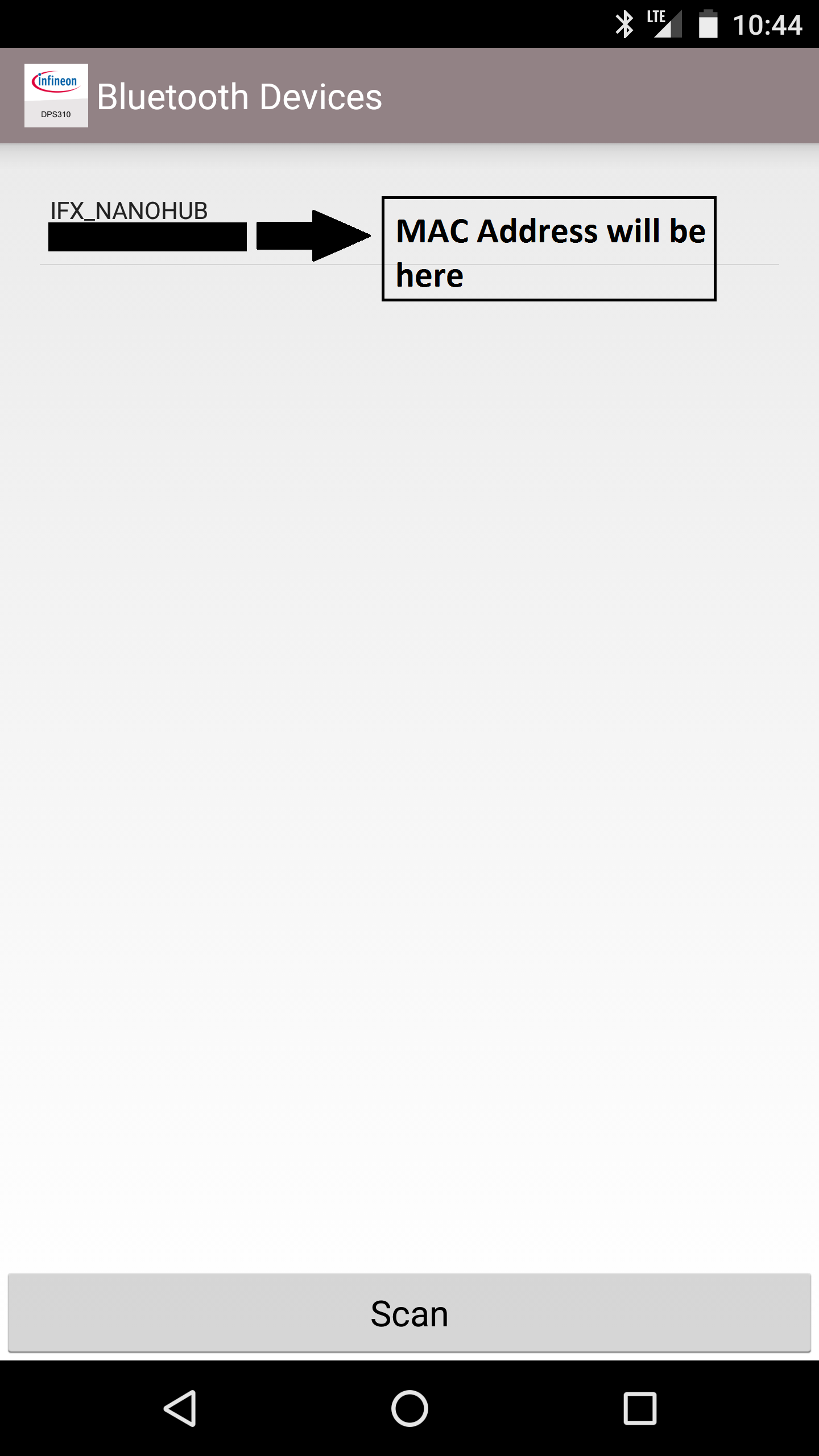
後で必要になるので、これを書き留めておきます。
注:現在使用していない場合は、スマートフォンからセンサーハブナノのペアリングを解除することをお勧めします。Bluetoothがオンになっているスマートフォンが近くにあり、センサーハブナノがペアリングされている場合、スマートフォンは自動的にスマートフォンに接続するためです。 。また、HC-05をセットアップして、Nano Hubとペアリングしようとすると、接続されません。
HC-05をATモードにする:
ATモードでは、HC-05Bluetoothモジュールの設定を構成できます。ボーレートを設定するか、スレーブデバイスとマスターデバイスのどちらとして接続するかなどを設定します。モジュールがInfineonのSensorHub Nanoからデータを正常に取得できるようにするには、モジュールのいくつかの設定を変更する必要があります。
<図>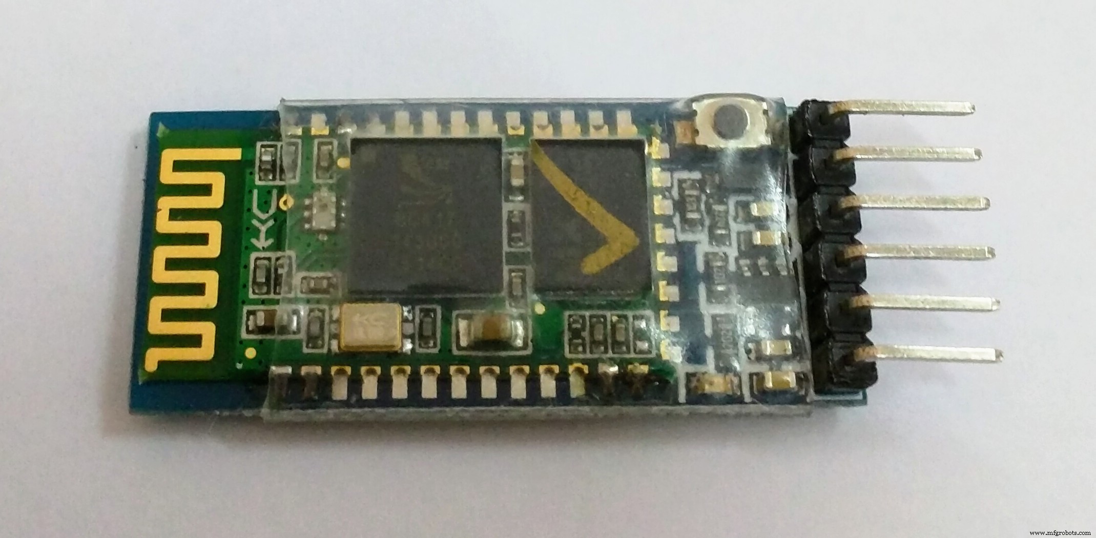
まず、「ATコマンド」スケッチをArduinoMKR1000にアップロードします。これにより、Arduino MKR1000を介して、ATモードでBluetoothモジュールにコマンドを送信できるようになります。
  // Martyn Curreyのブログの元のスケッチはこちら:
 // http://www.martyncurrey.com/arduino-with-hc-05-bluetooth-module-at-mode/
 //
 // Arduino MKR1000で動作するようにスケッチを変更しました!
 //
 //基本的なBluetoothスケッチ
 // HC-05モジュールを接続し、シリアルモニターを使用して通信します
 //
 // HC-05のデフォルト最初に電源を入れたときに通信モードになります。
 // ATモードにする必要があります
 //工場出荷時にリセットした後、通信モードのデフォルトのボーレートは38400です
 char c ='';
 void setup(){
 //ホストコンピューターとのシリアル通信を開始します
 Serial.begin(9600);
 Serial.println( "Arduino with HC-05の準備ができました");
 // 38400を使用してHC-05との通信を開始します
 Serial1.begin(38400);
 Serial.println( "Serial1は38400で開始しました");
}
 void loop(){
 // HC-05から読み取りを続け、Arduinoシリアルモニターに送信します
 if(Serial1.available())
 {
 c =Serial1.read();
 Serial.write(c);
}
 // Arduinoシリアルモニターから読み取りを続け、HC-05に送信します
 if(Serial.available())
 {
 c =Serial.read( );
 //コマンドをシリアルモニターにミラーリングします
 //コマンドを簡単に実行できるようにします
 Serial.write(c);
 Serial1.write(c);
}
}
次に、図に従って、BluetoothモジュールのみをArduinoMKR1000に配線します。
<図>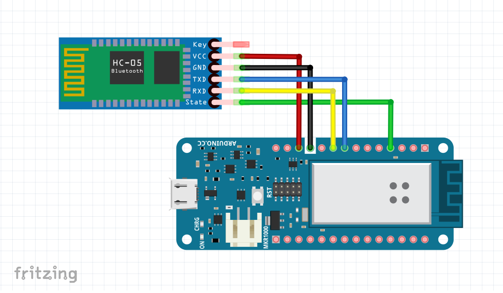
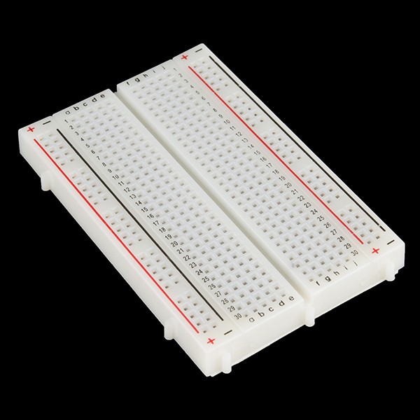
注:最初にすべてをブレッドボードに配線し、適切に設定したら適切な配線に進むことをお勧めします。
<図>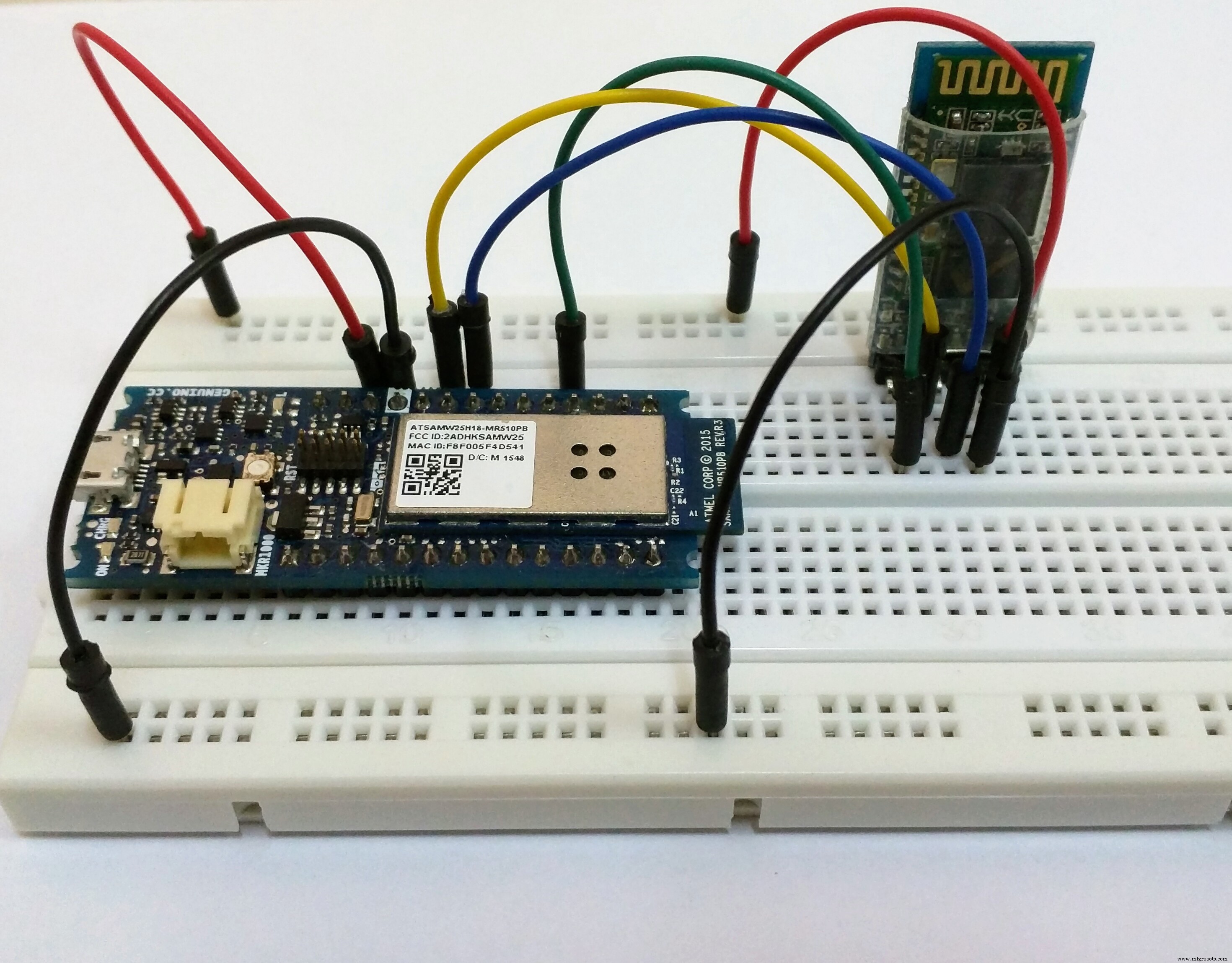
Sensor Hub NanoとHC-05をオンにしようとすると、現時点ではそれらが自動的に接続されないことがわかります。これが表示されます:
HC-05設定を変更するには、BluetoothモジュールをATモードにする必要があります。これを行う方法は、使用しているブレイクアウトボードによって異なるため、別の方法で行う必要がある場合があります。私が持っているものとは異なるモジュールをお持ちの場合は、ここにあるMartyn Curreyのブログにアクセスして、ATモードでHC-05Bluetoothモジュールを入手する方法の詳細を確認してください。行き詰まっている場合は、問題をグーグルで検索するかコメントしてください。サポートさせていただきます。
私のBluetoothモジュールにはボタンスイッチがあるので、ATコマンドモードにするには次の手順を実行する必要があります(ATコマンドコードをArduinoにアップロードすることを忘れないでください):
- モジュールの電源を切断します。 (TX回線とRX回線はまだ接続されています!)
- モジュールのボタンスイッチを押し続けて閉じます
- ボタンスイッチを押したまま電源を入れます
- LEDが点灯したら、スイッチを放します
ATモードでHC-05を取得する方法を示すビデオ:
ATモードに入ると、HC-05のLEDの点滅パターンにかなりの違いがあります。通信モードでは、LEDは1秒間に約5回すばやく点滅しますが、ATモードでは、LEDは数秒ごとに1回点滅します。
HC-05モジュールのセットアップ:
シリアルモニターを開き、ボーレートを9600に設定して、[NLとCRの両方]を選択します。
<図>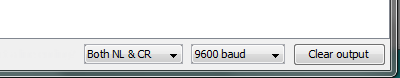
注:改行とキャリッジリターンに設定する必要があります。そうしないと、ATコマンドが機能しません。
シリアルモニターに「AT」と入力すると、「OK」が表示されます。もしそうなら、あなたはさらに進んで、私がしたようにコマンドを与えることができます。
<図>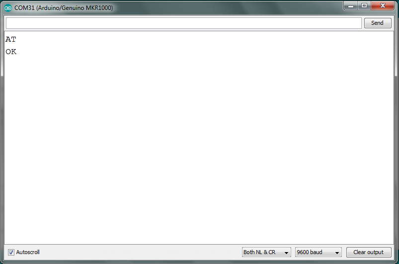
基本的に、ATモードでこれらの設定を変更する必要があります:
- 現在ペアリングされているデバイスをすべて削除する
- 指定したBluetoothMACアドレスにのみ接続できるようにします
- Bluetooth接続モードを「マスター」に設定します
- 接続に必要なMACアドレスを指定してください
- ボーレートを115200に設定し、ストップビットを2ビット、さらにはパリティに設定します
上記の手順は、別のBluetoothモジュールを使用している場合でも、コマンドとその機能を参照して使用できるようにするためのものです。しかし、ここで、HC-05がSensor HubNanoとペアリングするために与えたコマンドをリストします。
- AT + RMAAD
- AT + CMODE =0
- AT + ROLE =1
- AT + BIND =1234,56、abcdef(Sensor Hub NanoのMACアドレスに置き換えてください)
- AT + UART =115200,0,0
参考までに、ATコマンドのログを次に示します。
<図>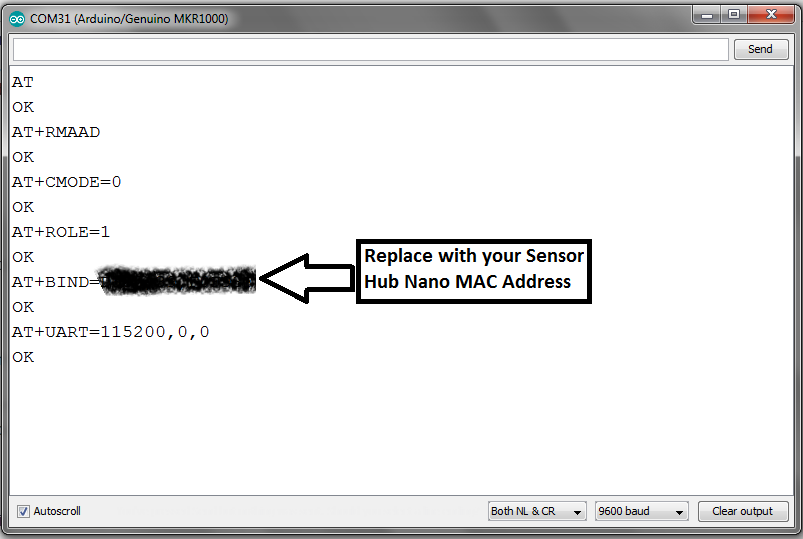
ここで、Arduinoのプラグを抜いて、Bluetoothモジュールをオフにする必要があります。これにより、通信モードに戻ります。
注:HC-05設定で何かを台無しにした場合は、モジュールをデフォルト設定にリセットし、コマンドAT + ORGL で最初からやり直すことをお勧めします。
接続のテスト:
ここで、最後のステップが成功したかどうかをテストする必要があります。これを行うには、Sensor HubNanoをオンにします。青いLEDは、数秒に1回、非常にゆっくりと点滅します。次に、ArduinoをPCに接続し、HC-05とSesnor HubNanoの両方でLEDの点滅の変化に注意してください。
今まばたきを見て、前のまばたきと比較してください:
顕著な違いがあり、両方のモジュールが接続されていることを知っておく必要があります。これで、プロジェクトの配線とテストの次の部分に進むことができます。
注:以前にスマートフォンをSensor Hub Nanoとペアリングしたことがある場合は、ペアリングを解除する必要がある場合があります。そうしないと、接続の問題が発生します。一度に接続できるデバイスは1つだけです。
必要最低限のプロジェクトのテスト
LEDの点滅パターンでHC-05とSensorHub Nanoが正しく接続されていることを確認したら、スマートフォンでのBlynkアプリの設定に進みます。
Blynkアプリの設定:
ここからiOSまたはAndroidデバイス用のBlynkアプリをダウンロードし(まだダウンロードしていない場合)、BlynkアプリからQRコードをスキャンします。この時点で必要な基本的なウィジェットが自動的に複製されます。
<図>
同様の画面が表示されます:
<図>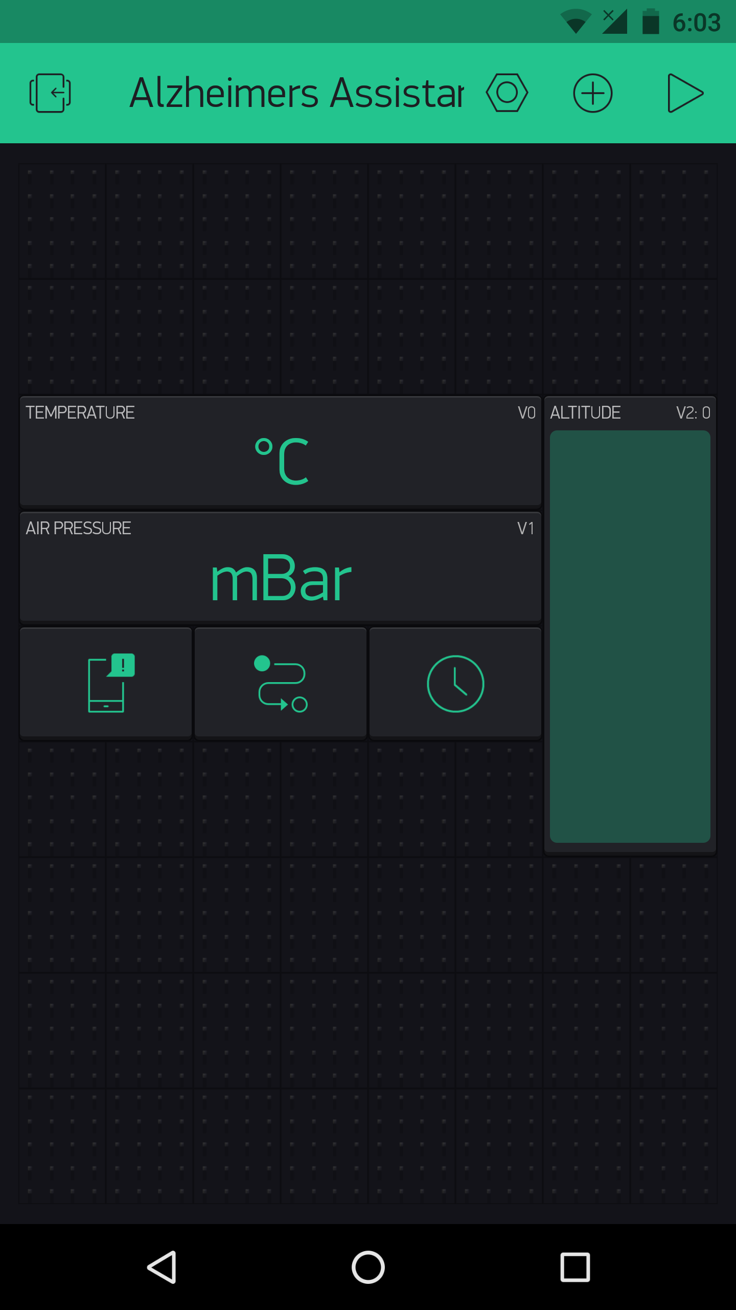
この時点ではここで変更を加えず、読み進めてください。
必要なライブラリのインストール:
コードをエラーなしでコンパイルするには、ArduinoIDE用に2つの異なるライブラリをインストールする必要があります。それらは:
- ブリンク 、スマートフォンに接続するには
- u8g2lib 、表示用
必要なライブラリをインストールするには、2つの方法があります。 1つ目は、Arduino IDEの新しいバージョンで使用できる「ライブラリマネージャー」を使用する方法で、2つ目は手動インストールです。ここでは両方の方法について詳しく説明しているので、ここでは説明しませんので、リンクを確認してください。
<図>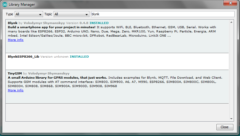 <図>
<図> 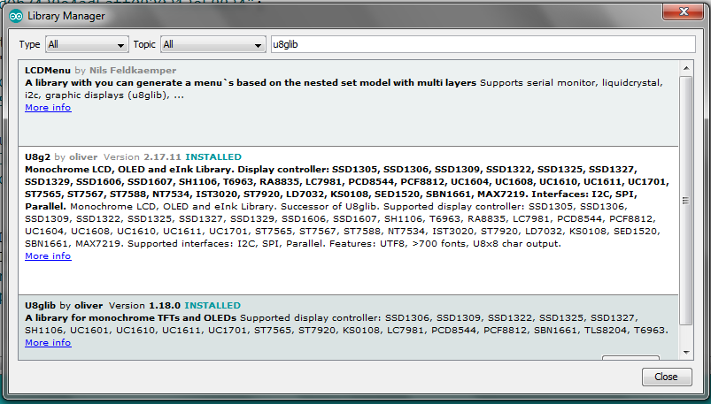
コードのアップロードとテスト:
ライブラリをインストールしたら、添付のコードをダウンロードして変更を加えます。 Blynkからの認証コード(Blynkで新しいプロジェクトが作成されたときに電子メールで送信されます)と、WiFiSSIDおよびパスワードを追加する必要があります。それが完了したら、コードをMKR1000にアップロードします。
コードをアップロードした後、回路図に従って回路を配線します。
<図>
次に、スマートフォンでBlynkアプリを開き、アルツハイマー病のアシスタントプロジェクトを開いて、再生ボタンを押します。 MKR1000(HC-05とディスプレイを配線した状態)を接続すると、ディスプレイにアルツハイマー病のアシスタントのロゴが表示されます。しばらく留まると、「センサーハブナノを待っています」というメッセージが表示されます。 」。 Sensor Hub Nanoの小さなスイッチをオンにして、HC-05モジュールのBluetooth範囲内にいることを確認します。 「 InfineonのセンサーハブNanoに接続されています」と表示されているはずです。 "、そして数秒後、スマートフォンに気圧の温度と高度の値が表示されます。
<図>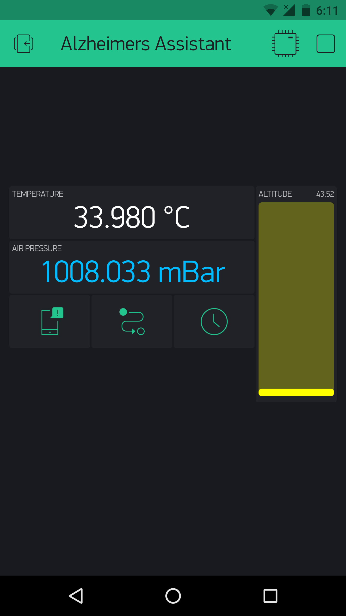 <図>
<図> 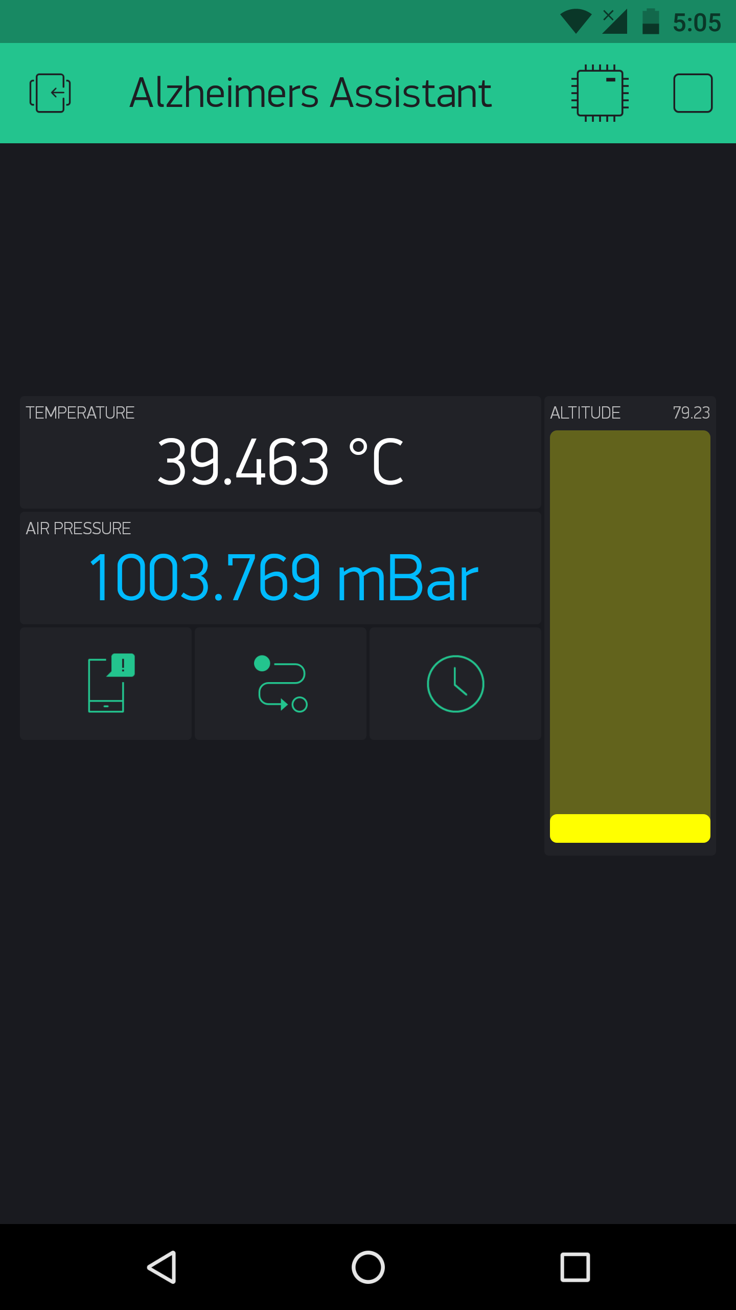
また、数秒後、時刻と日付が24時間形式で表示され、インターネットと同期されます。
これはそれをテストするビデオです:
もしそうなら、おめでとうございます、あなたはそれをセットアップするという難しい部分を完了しました、そして今、彼らの好みに応じて、個々の患者のためにそれをパーソナライズするようになります。
アルツハイマー病のアシスタントのパーソナライズ
これまでの設定では、インフィニオンのDPS310からセンサーデータをすっきりとしたエレガントな設定で取得していますが、そこから何か便利なものを作成するには、個々の要件や好みに応じて設定を構成する必要があります。したがって、このセクションでは、コードと、各ユーザーの好みに応じて機能するようにアルツハイマー病のアシスタントを変更する方法について説明します。各「機能」のコードスニペットを提供します。少し変更を加えるだけで、メインコードに追加できます。
注:「ベアボーンプロジェクト」用に添付したコードを見ると、BlynkTimerでラップされた関数を使用していることがわかります。指定した間隔でタスクを実行できるため、カスタマイズを行う場合や、ハードウェアがBlynkに大量のリクエストを送信するときに発生するBlynkフラッドエラーを防ぐために、これらを使用することをお勧めします。また、すべての関数が存在するがメインコードには含まれていないという意味で、コードは「必要最低限」です。ユーザーは要件に応じてメインコードを編集する必要があり、各関数が実行される時間間隔を調整する必要がある場合があります。
DPS310:-
<図>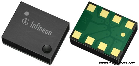
インフィニオンのDPS310は、非常に小さなフォームファクタで、非常に高い精度を提供する低コストのデジタル気圧センサーです。そのため、このようなプロジェクトでの使用に最適であり、値を使用して、高齢の患者の転倒、または患者が正確にどの部屋にいるかを検出できます。
注:私はまだスマートウォッチエンクロージャーを作成していません。そのため、次の画像のように、Bluetooth経由でArduinoに接続されたSensor HubNanoを手に使用しています:
<図>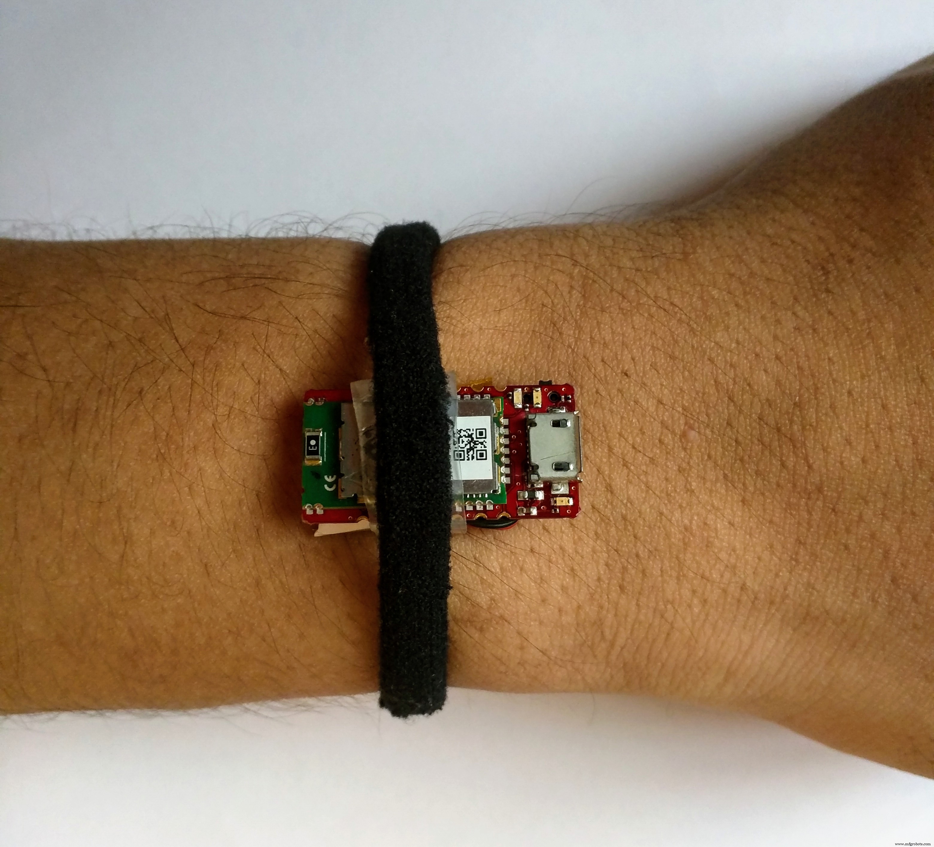
落下検出: 落下を検出するには、落下値(指定された時間の2つの読み取り値間の気圧の差)を指定し、クリアランスを設定する必要があります。たとえば、2つの連続する値の間の高度の変化(たとえば1秒の時間)が落下値±クリアランス値の間にある場合、落下が検出されます。
<図>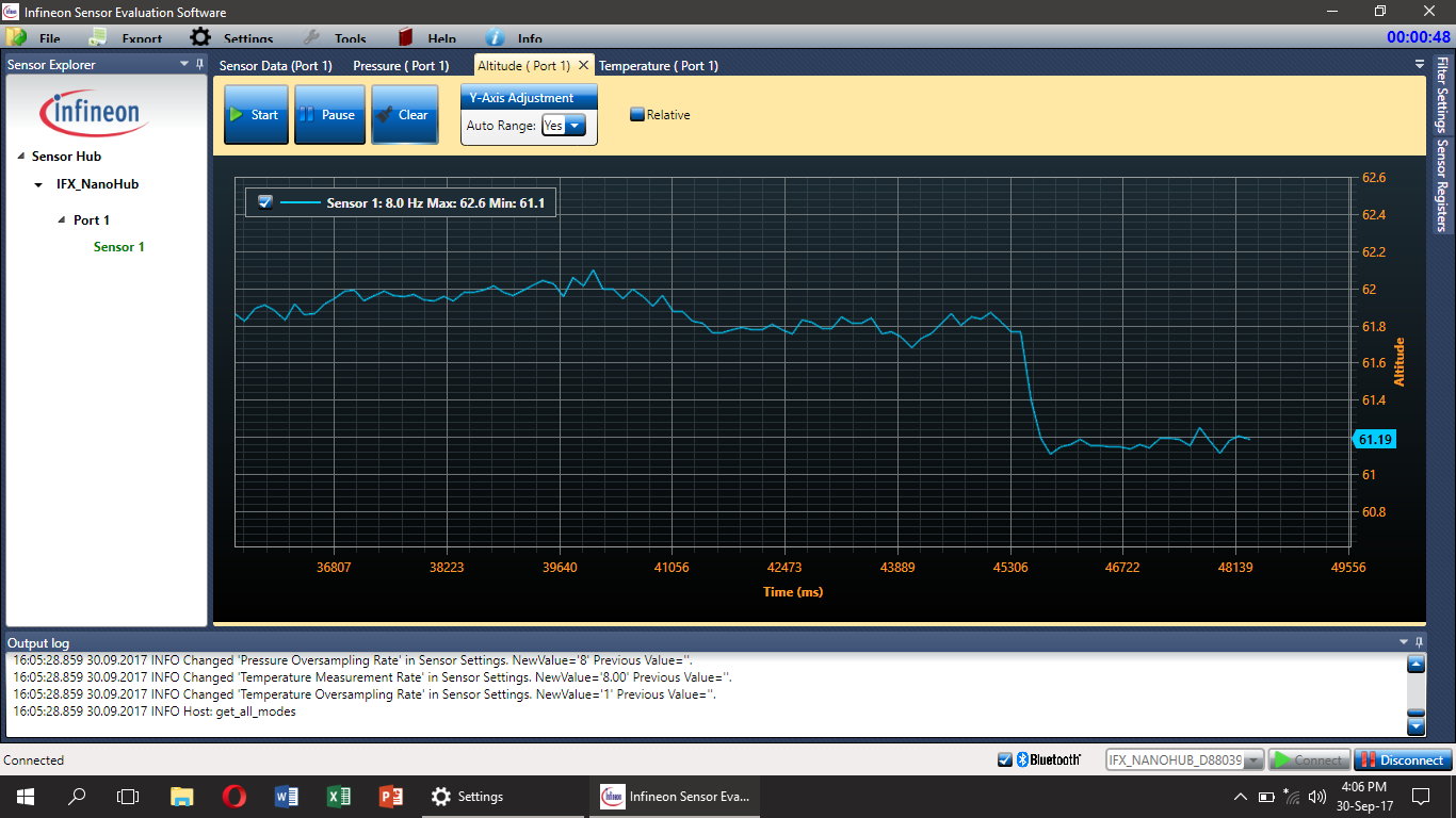
いくつかのテストを行ったところ、立ち下がり値は0.7、クリアランス値は±0.2である必要がありますが、すべての状況で機能するとは限りません。これは、人が転倒したときにさまざまな方法で発生する可能性があるという単純で理解しやすい理由によるものです。したがって、転倒検知システムの精度を高めるためには、二次センサー(おそらく加速度計)の使用が必要であり、それは将来の作業に追加されます。しかし、転倒を検出するための他のより正確なアルゴリズムが常に存在する可能性があり、私はそれらを聞くことにオープンです。これについて何かアイデアがあれば、遠慮なくコメントしてください。
転倒の検出を示すビデオ:
患者の居場所の検出: これは、落下検出アルゴリズムと同様に機能します。たとえば、患者がどの階にいるかを知る必要がある場合は、現在の高度値を取得して、前の高度値から差し引くことができます。次に、その差を事前定義された値と比較します。これにより、患者がどの階にいるかがわかります。
<図>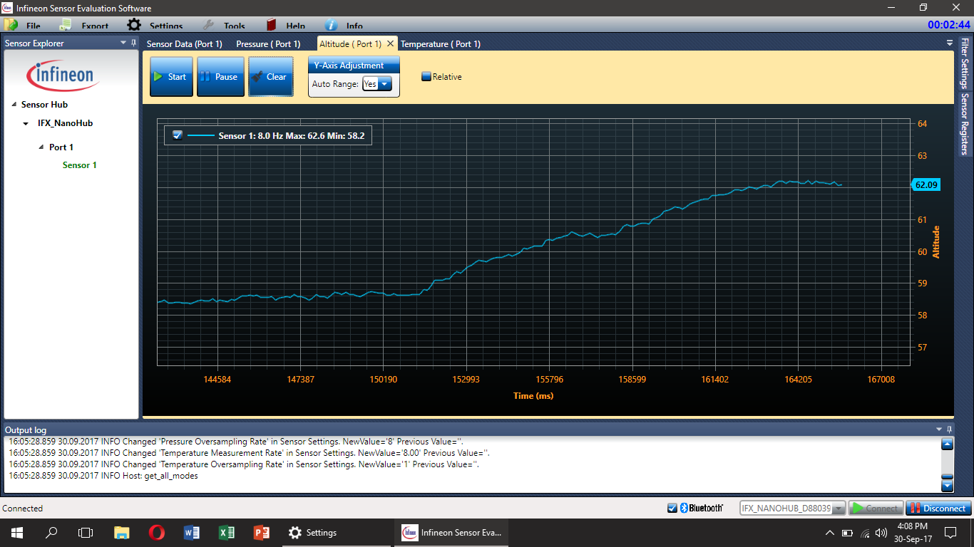
単純なifおよびelseロジックを使用して、患者がどのフロアにいるかを判断するだけです(高度値はメインコードにすでに存在します)。これは、BlynkのLEDウィジェットを使用して示すことができます。
注:メインコードに位置検出を含めていませんが、ユーザーは必要に応じて位置検出を追加できます。Blynkタイマー関数として使用することを忘れないでください。
同じ手法を使用して、人がどの部屋にいるかを検出することもできます。その場合、モーションセンサーなどのセカンダリセンサーが必要になります。そうしないと、誤ったトリガーが多数発生する可能性があります。
温度: DPS310は、火事など、患者に発生する可能性のある事故について警告するために使用できる温度値も示します。温度が特定の値まで上昇した場合、たとえば45℃で世話人に警告します。
<図>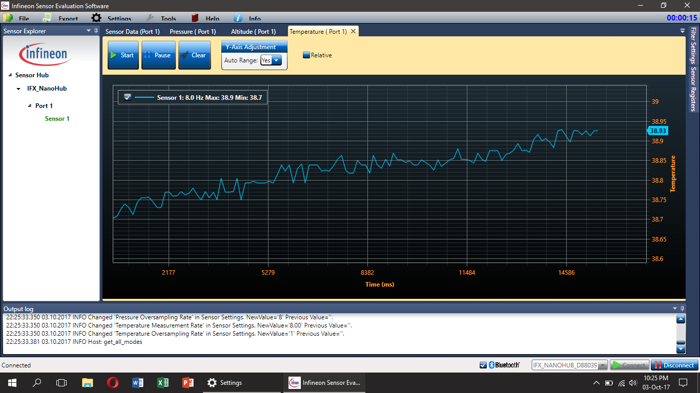
しかし、DPS310センサーは(少なくともこのユースケースでは)皮膚に直接取り付けられていないため、得られるのは体温ではありませんが、センサーハブナノの温度であると言った方が正確です。
このためのコードは非常に単純で(メインループのどこでも使用できます)、次のようになります。
  if(t> maxTemp){
 //温度が最大値よりも高い場合は必要な操作を行う
}
 else {
 //必要な操作を行う温度が最大値より低い場合
}
注:上記のグラフはすべて、インフィニオンが提供するSESG2評価ソフトウェアを使用して作成されています。
ブザーとスイッチ:-
これについては前に触れませんでしたが、ブザーとスイッチもシステムに存在する必要があり、それらも非常に役立ちます。たとえば、薬を服用するときなどにブザーを使用して患者の注意を引き付けたり、スイッチを安全装置として使用したりできます。
<図>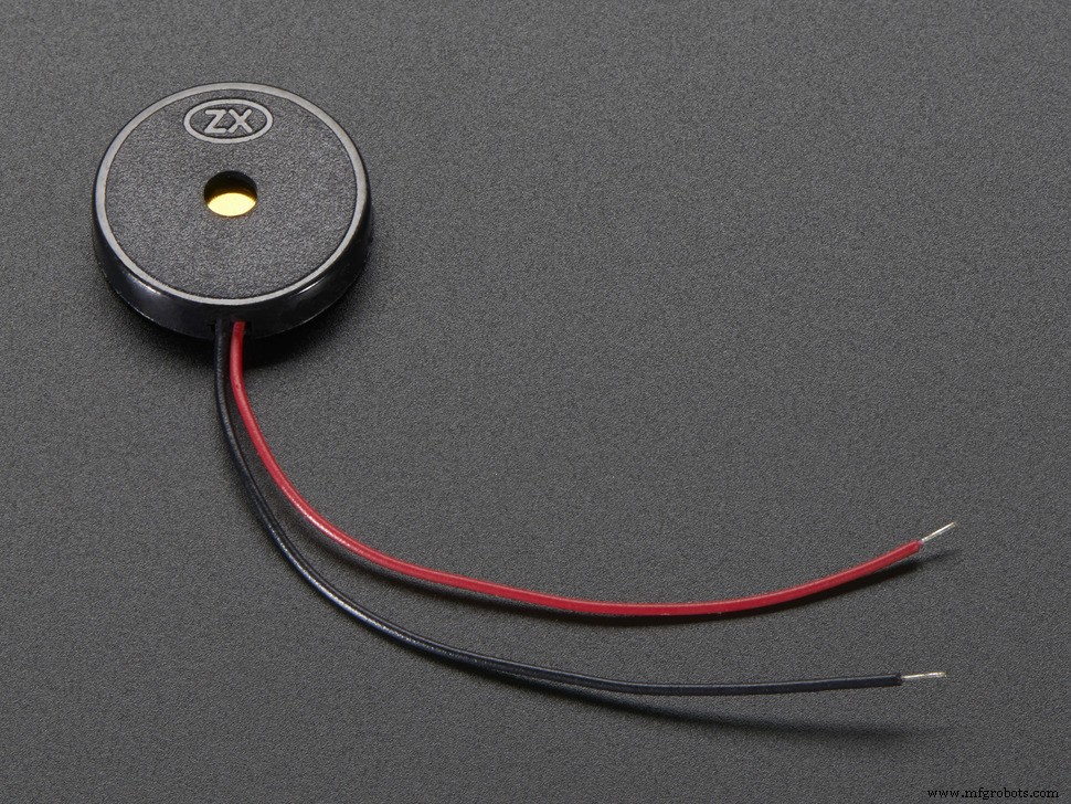 <図>
<図> 
また、Blynkを使用するため、ボタンスイッチを押すと、管理人の電話に通知が表示されるか、SMSを呼び出したり送信したりするように設定できます(IFTTTを使用して行うことができ、後で提供されます)。 )。これは、それを行うためのコードスニペットである可能性があります:
  void emailOnButtonPress()
 {
 // ***警告:15秒ごとに1通の電子メールのみを送信するように制限されています。 ***
 //ボタンを押したときに電子メールを送信しましょう
 // Arduinoのデジタルピン2に接続されています
 int isButtonPressed =!digitalRead(2); //ボタンが「アクティブLOW」であるため、状態を反転します
 if(isButtonPressed)//電子メール送信をトリガーする条件を記述できます
 {
 Serial.println( "ボタンが押されました。 "); //これはシリアルモニターで確認できます
 Blynk.email( "[email protected]"、 "Subject:Button Logger"、 "ボタンを押しただけです...");
 //または、アプリで指定されたメールを使用する場合(アプリのエクスポートなど):
 //Blynk.email("Subject:Button Logger "、"ボタンを押しただけです。 .. ");
}
}
これはBlynkサンプルコードから取得され、割り込みを使用してボタンをチェックします。これは、転倒検出アルゴリズムによって検出されなかった転倒などの緊急時に、患者が世話人に警告するために使用できます。ここで完全なサンプルコードを入手できます。このコードは、ボタンが押されるとメールを送信します。
ブザーを使用してトーンを生成し(Arduinotone()コマンドを使用-詳細はこちら)、投薬や運動などのタスクを患者に思い出させることができます。
ディスプレイ:-
ユーザーが実際に見るプロジェクトの主要部分は、ディスプレイです。 The Nokia 5110 displays are commonly available, easy to set up and cheap, but they aren’t that flashy, especially when used in such a system. OLED displays with a higher resolution will be a very good alternative to it, and you can easily modify the code to work with one because I used the u8g2 library (github here). Choose any of the display models from here, and add it to the start of the sketch (removing the Nokia 5110 line, of course!). You will need to wire it up according to what it is in the code and you’re ready to go. You can also use bitmap images with a higher resolution display. You can also change the font for the text on the display, select fonts from the huge list here and edit the name of the font in the code.
Note:You may have to change the pixel positions for the text in the code if you use a display with a higher resolution.
That was just a brief description of the library used to get the display working. But, now I will tell you how to edit the code to get Alzheimer's Assistant to show the time or the Sensor Hub Nano data (temperature, Altitude and pressure).
Displaying time: To display the time, you could simply use an RTC (or time keeping module) but as we're connected to the Internet, it would be much more easier to use the Internet to sync the time. And as we're using Blynk that would make it even more simpler. You just need the RTC widget in your project. Now with a few lines of code, you can automatically retrieve the time from the Blynk server (Make sure to set your timezone from the Blynk widget). The main code is set to display the time by default (not the sensor values, discussed next)
Note:The time displayed on the screen could go up or down a minute, as it is synced from the internet, but despite that, I have tested it for a long time and have found it to be very accurate (just a difference of a few seconds).
<図>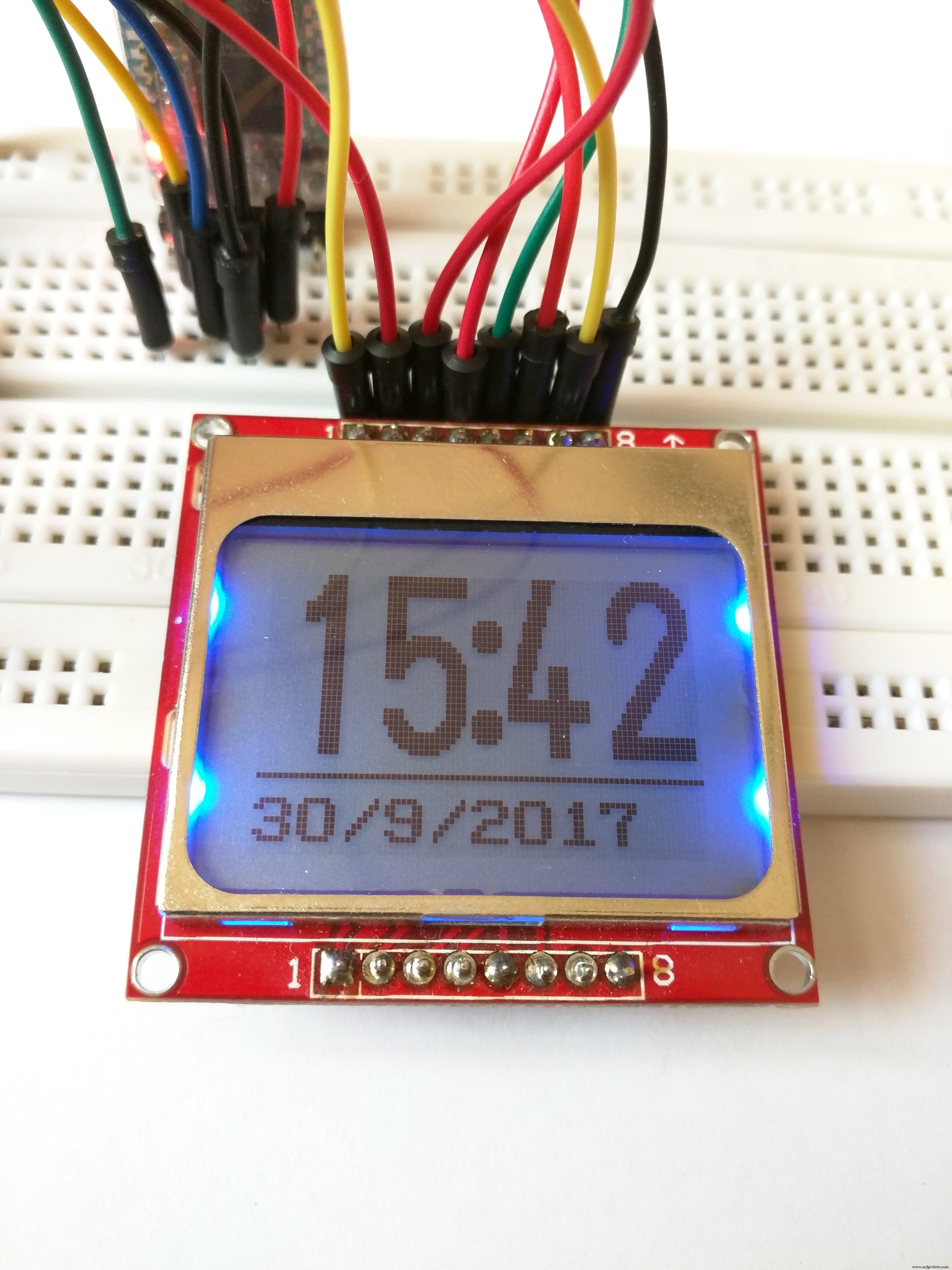
Displaying the Sensor Hub Nano data: We could just as well display data from the Sensor Hub Nano in the display. Not that it would benefit the patient, but its good for debugging purposes, should you need it. That can be done with the following code snippet:
void showSensorValues() {
 //Shows the sensor values on the display
 char bufT[10];
 char bufP[10];
 char bufA[10];
 String(t).toCharArray(bufT, 10);
 String(p).toCharArray(bufP, 10);
 String(a).toCharArray(bufA, 10);
 u8g2.clearBuffer();
 u8g2.setFont(u8g2_font_6x10_tf );
 //Display the temperature
 u8g2.drawStr(0, 10, "T:");
 u8g2.drawStr(12, 10, bufT);
 u8g2.drawStr(73, 10, "C");
 u8g2.drawCircle(70, 4, 1, U8G2_DRAW_ALL);
 u8g2.drawHLine(0, 12, 85);
 //Display the pressure
 u8g2.drawStr(0, 26, "P:");
 u8g2.drawStr(12, 26, bufP);
 u8g2.drawStr(60, 26, "mBar");
 u8g2.drawHLine(0, 28, 85);
 //Display the altitude
 u8g2.drawStr(0, 42, "A:");
 u8g2.drawStr(12, 42, bufA);
 u8g2.drawStr(72, 42, "m");
 u8g2.drawHLine(0, 44, 85);
 //Send the values to the display
 u8g2.sendBuffer();
}
Don't forget to run this command to get the sensor data below:
getSensorValues(); But that's not all for the display. As I said in the start, Alzheimer's Assistant should be able to remind the patient of the tasks which need to be done daily, such as when to take medications or to remind the patient to exercise.
<図>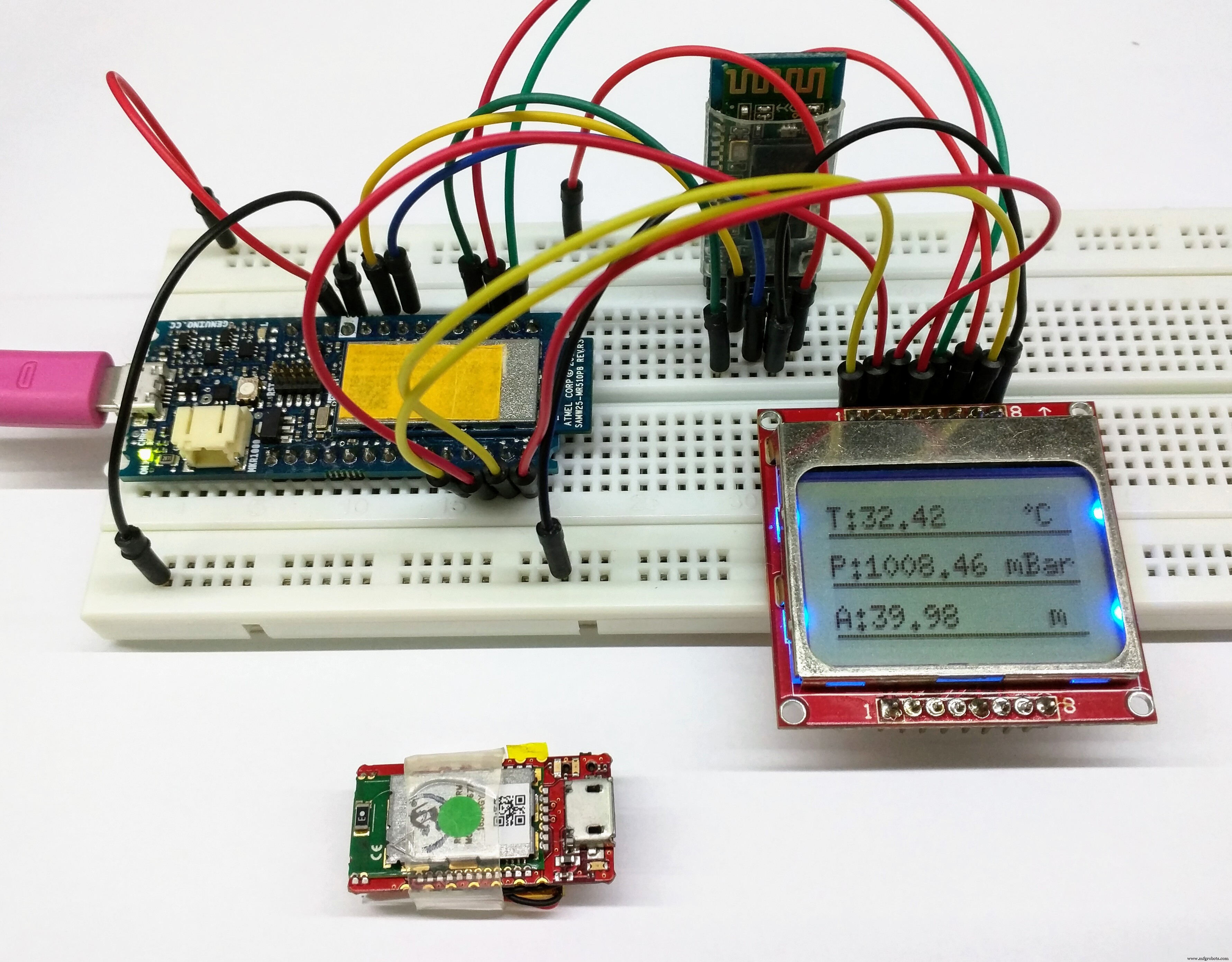
Using Eventor widget to remind:-
For that, we will be using the Eventor widget (check here for details) in Blynk.
Add the Eventor widget into your project (It's already there if you scanned the QR code above), and just follow the screenshots to see how to set it up:
<図>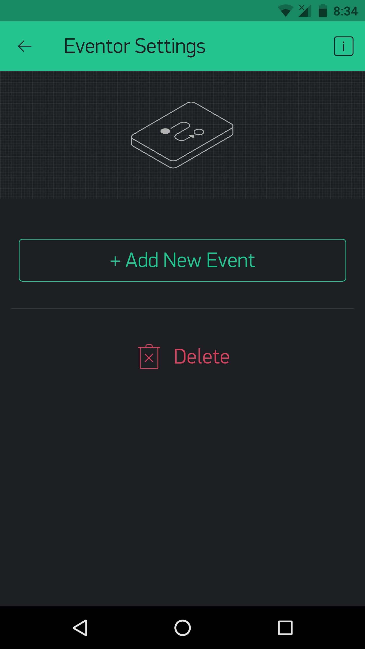 <図>
<図> 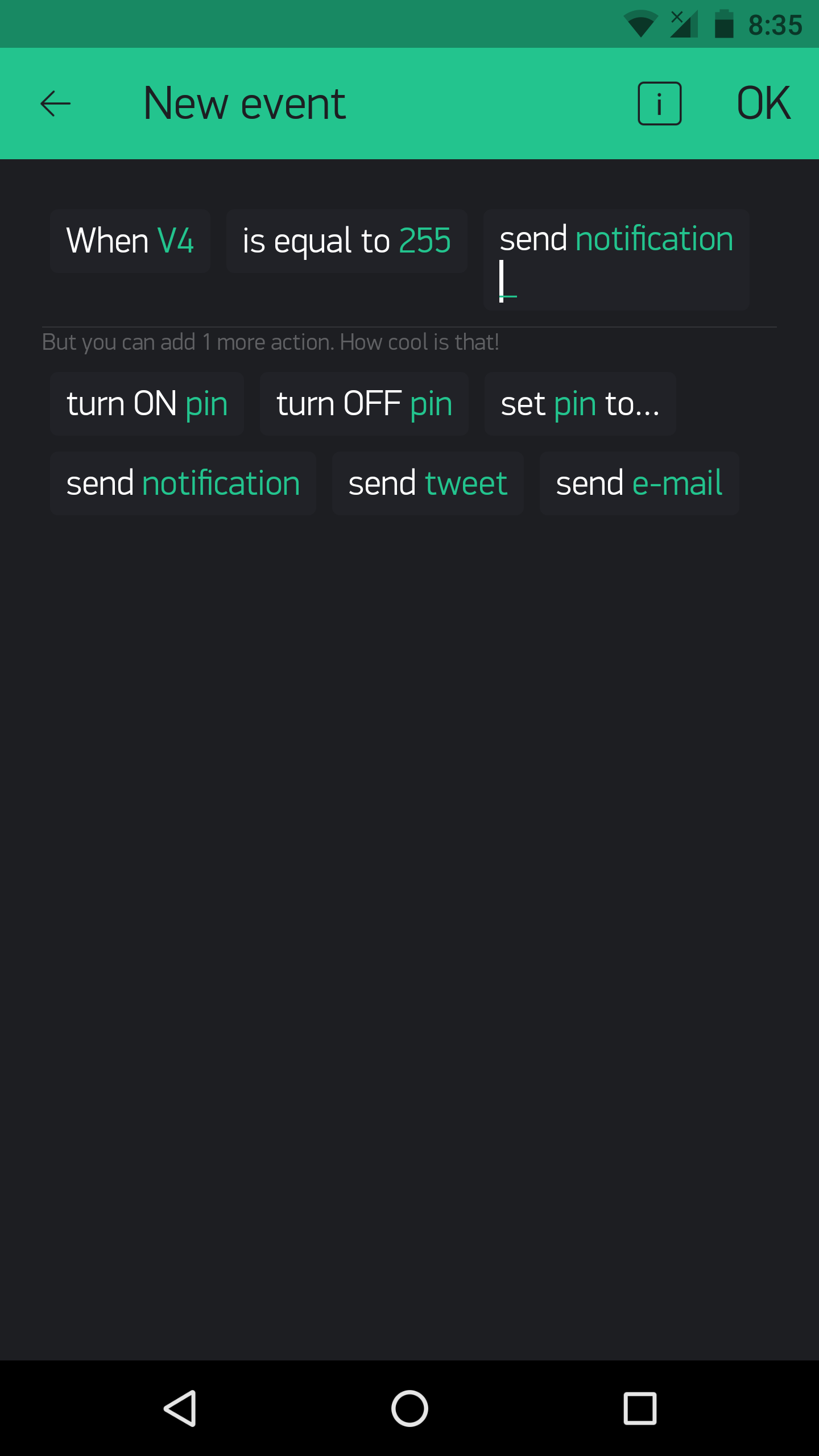 <図>
<図> 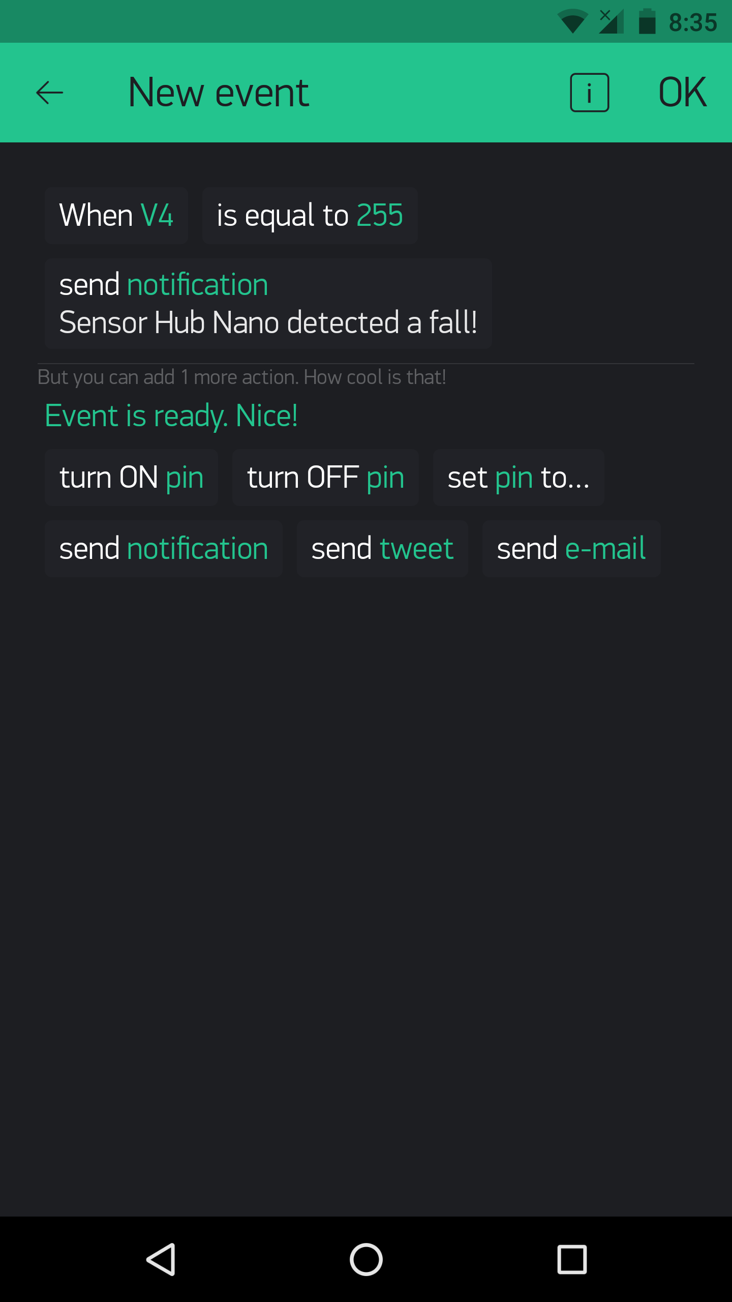
In the above example, the Eventor widget is used to set up a fall detection notification.
Using the Eventor widget to remind is done by this code:
BLYNK_WRITE(vEVENTOR_PIN) {
 //Use the Eventor widget to check if it's time to do a task (take medication in this case)
 int currentValue =param.asInt(); // 0 to 1
 if (currentValue ==1) {
 //Do here what you want to when its time for medication
 showPillReminder();
 playBuzzerReminder();
 //This is just a tone, I haven't made it in the main code, but you can if you want!
 }
 else {
 //If it's not the time for medication, do nothing
 }
}
And the result on the display when it's the time for medication:
<図>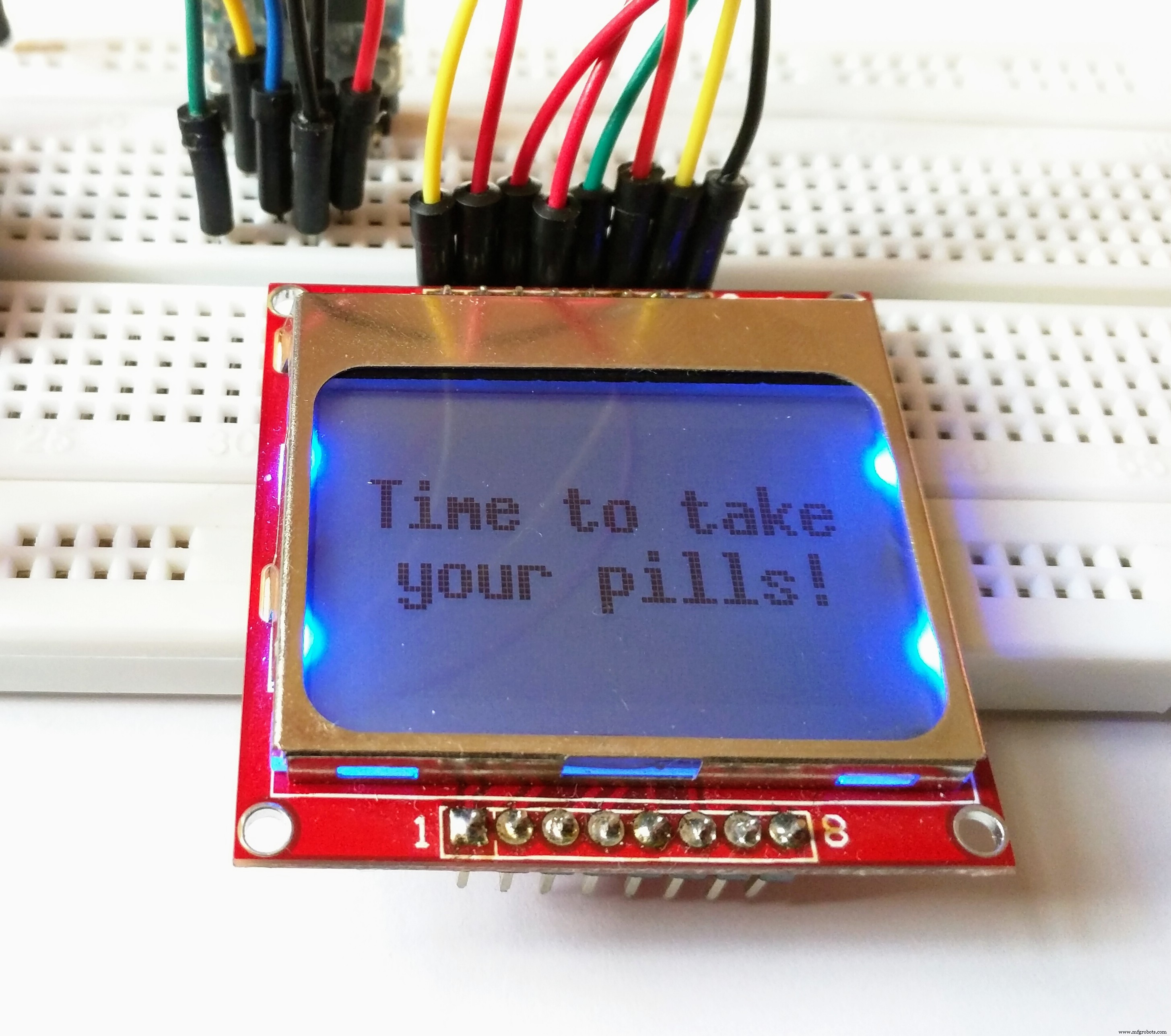
The same for exercise:
<図>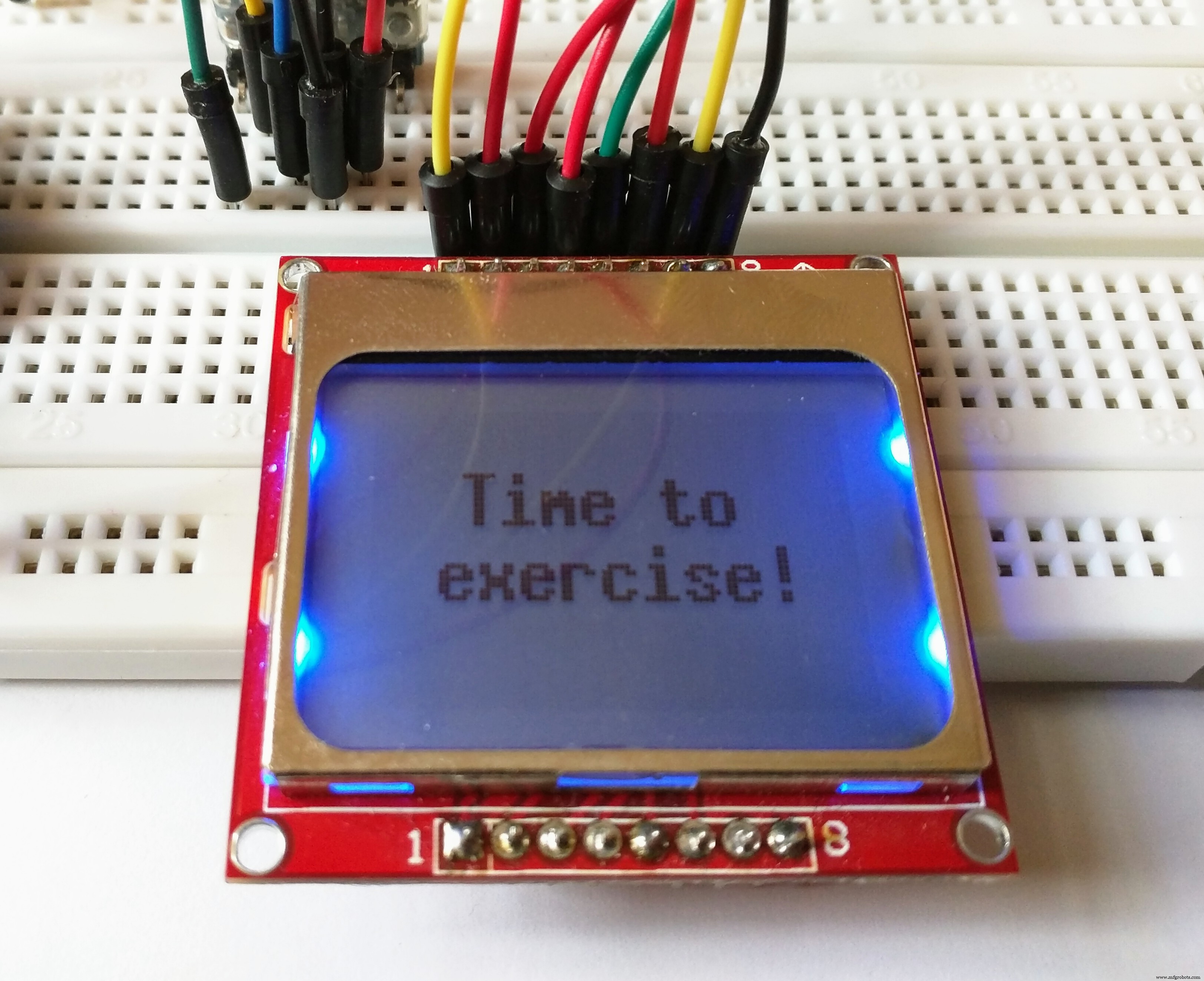
This is done by typing:
showExerciseReminder(); Instead of:
showPillReminder(); The eventor widget could, as said above, be used for a number of things. For example, you could set that an increase in temperature could result in sending an e-mail, and with no code modification!
Using different modes of the Sensor Hub Nano:-
You can test out the use of different modes for the Sensor Hub Nano. Using the following commands:
sendCommand(LOW_ENERGY);
sendCommand(STANDARD_MODE);
sendCommand(HIGH_PRECISION);
Using Blynk to switch modes could be more efficient. For that, set up your Blynk app like this:
<図>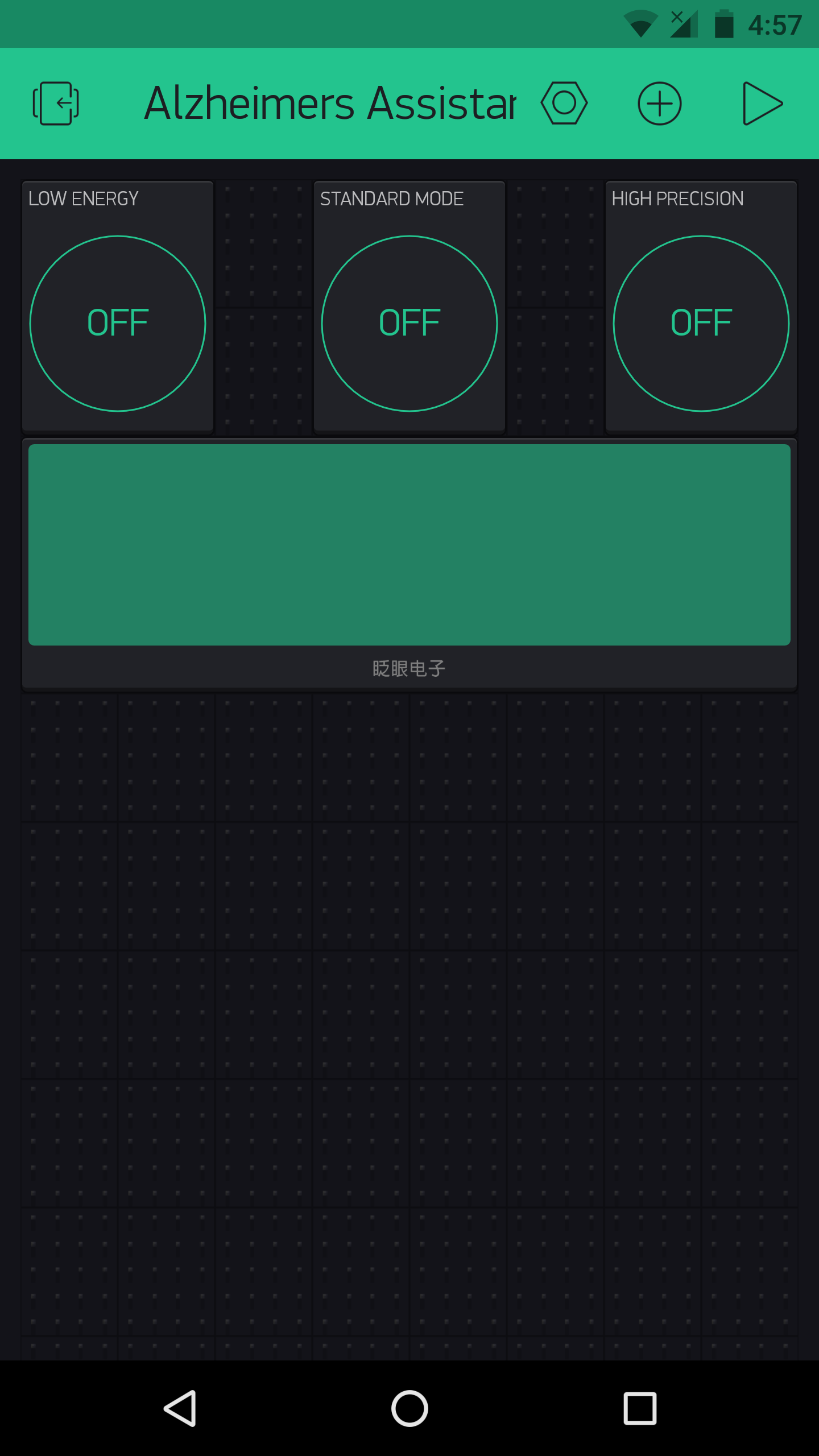
As this had no use for me, I did not add it it in the main code, but you could always do so as needed (The commands are present, you just need to add them with a bit of logic in the main sketch).
Using Blynk and IFTTT:-
Blynk can allow any Arduino project to easily harness the power of IFTTT.
<図>
This is because you can use Blynk to send a webhook request to the IFTTT Webhooks channel (previously called Maker channel), and you could create an IFTTT applet which waits for the webhook to be triggered (from the Blynk and Arduino side) and you could get it to trigger anything else in response to that.
A simple example on how to use IFTTT and Blynk with webhooks :
The Blynk webhook widget could be used to send a webhook request like this:
<図>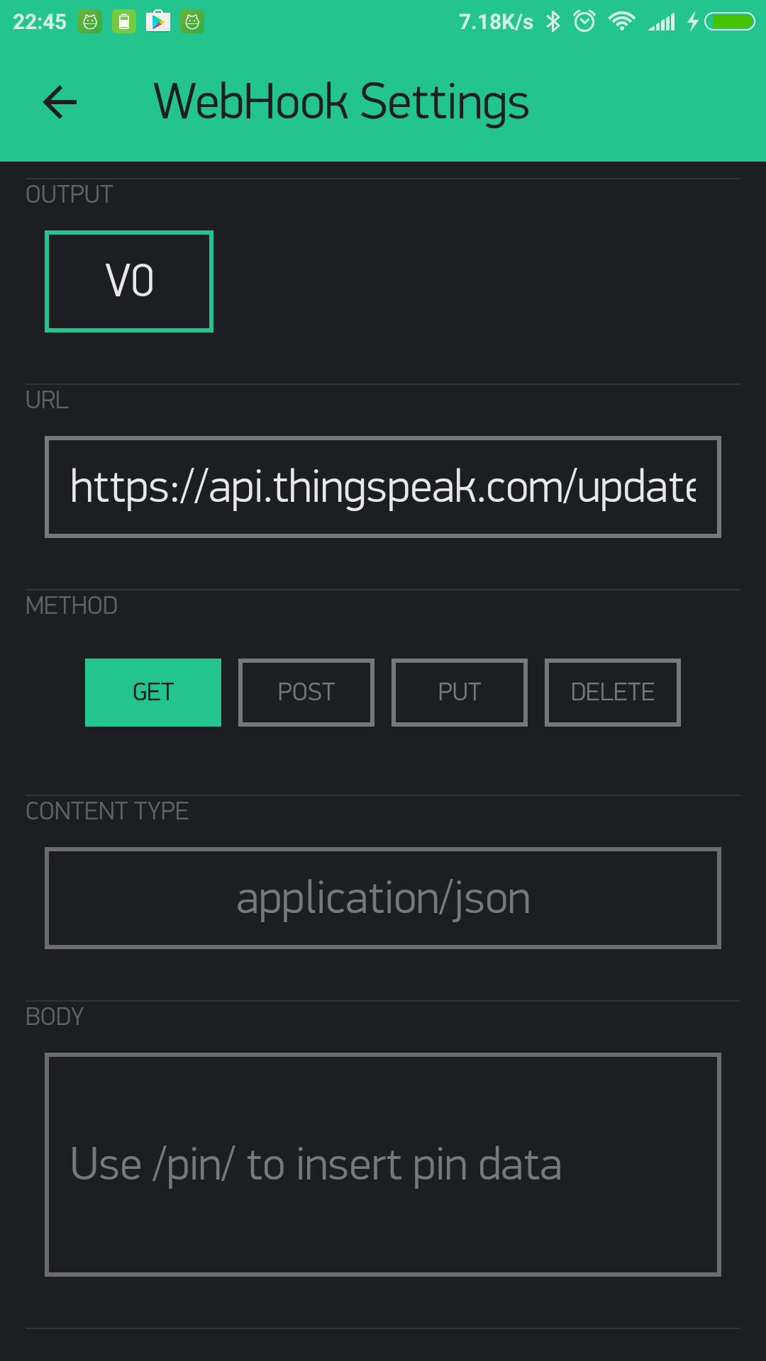
This is the IFTTT webhook channel:
<図>
And using webhooks to trigger IFTTT is not the only method. IFTTT can also be triggered by using Blynk to send emails and tweets.
<図>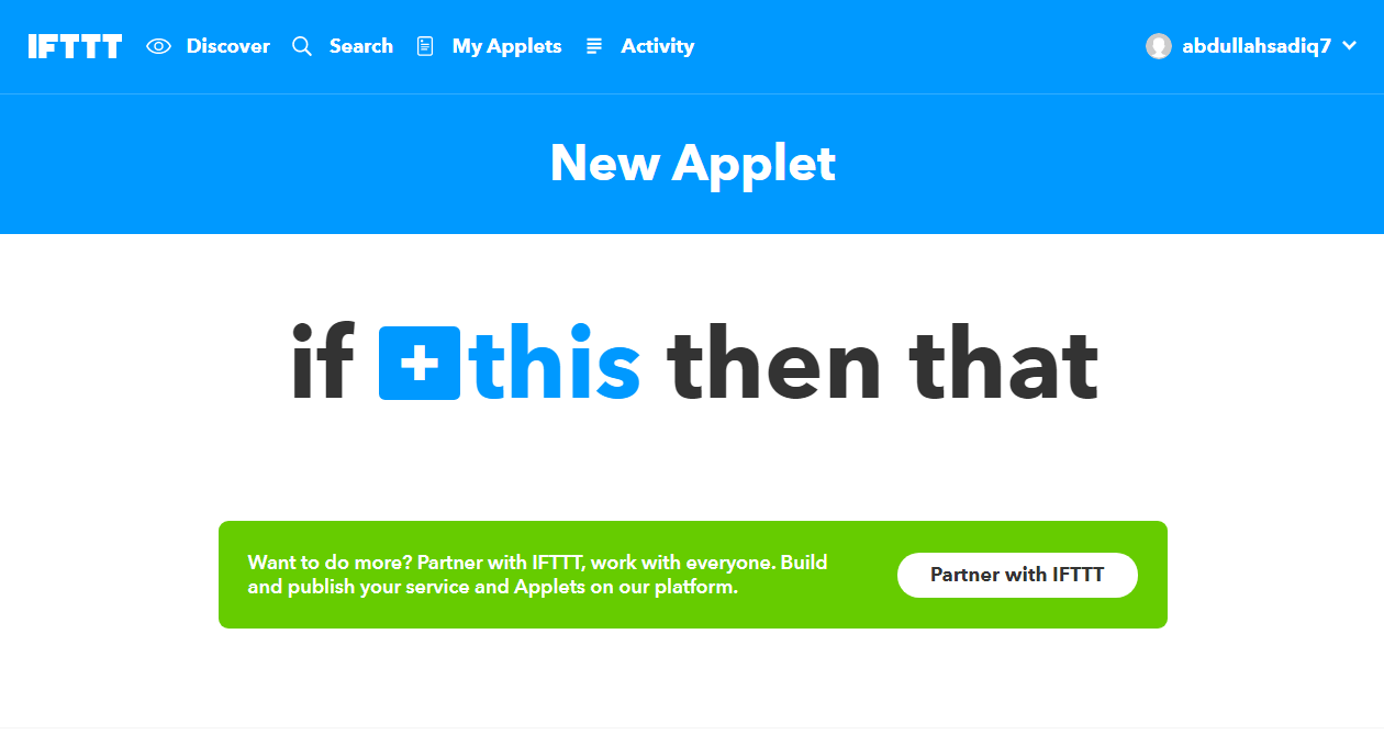 <図>
<図>  <図>
<図> 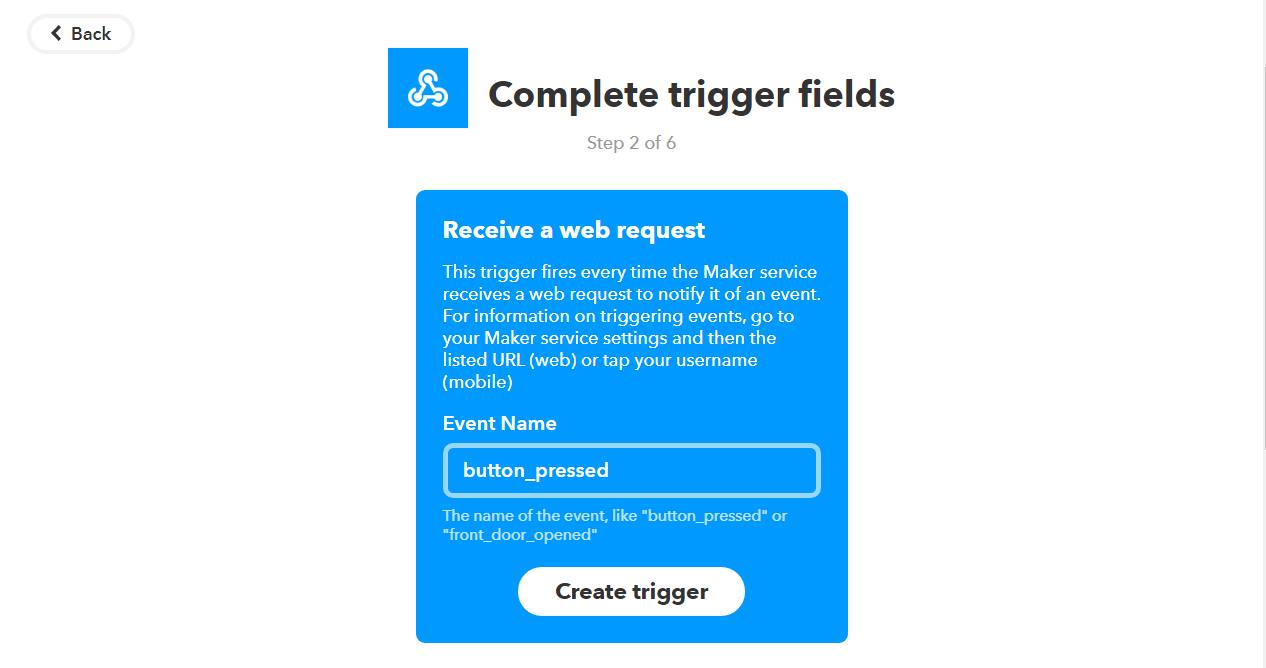 <図>
<図> 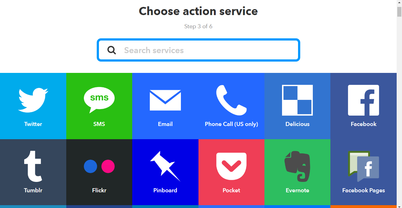 <図>
<図> 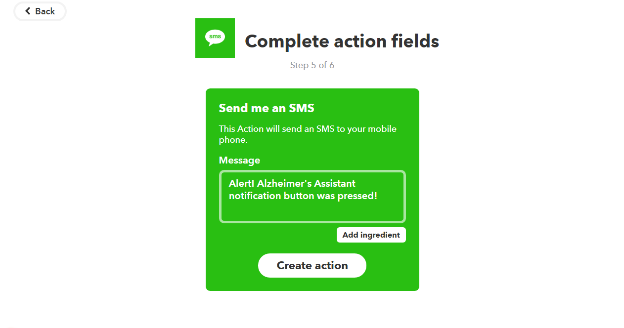
You have now made an applet. Time to test it.
Open "Services" in IFTTT and then select "Webhooks". Go to "Settings" and there you will see a URL. Copy that and open it in a new tab. There, instead of {event}, type the event name (which you set earlier). That was "button_pressed" for me, and so when I click on "Test it", this is the result after a few seconds:
<図>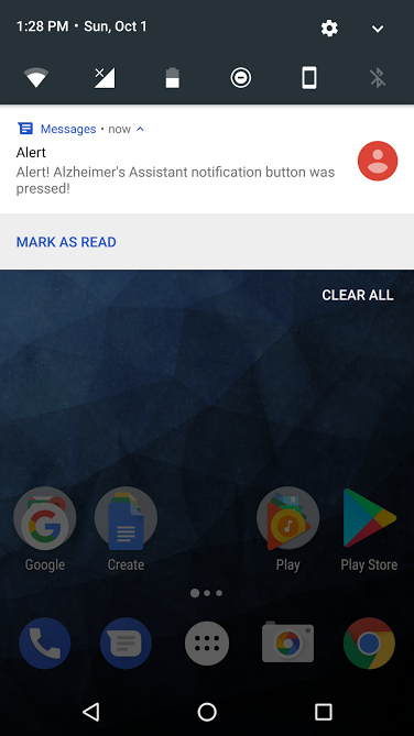
Now that you have confirmed the Webhook works, you can just write the URL in the Blynk webhook settings and get a GET or POST request (through the Blynk webhook widget)
And, instead of SMS, you could just as well use phone calls, or even Twitter and Facebook, if you want, and it's just as simple That is the power of IFTTT.
It's the same thing as my smart home controller project here, and I also discussed it in detail there, but it is a great thing which I couldn't go by without mentioning.
Final Touches
By now, almost all of the electronics part of the project is complete, but a few things still remain. Read on for them, and in the end, I will list the future work which should be done to improve this project.
Battery and charging:
The MKR1000 has a port for a LiPo battery, which means you could attach one. But I don't have one at the moment so I will not be going into that but you should check out the website for the Arduino MKR1000 if you need information on that.
For charging, you have two options, using the MKR1000 USB port directly, and the other one is to use wireless charging, if you have it. I will be using the wireless charging for it. This is because I already have a wireless charging receiver and transmitter made by Futara Elettronica.
<図>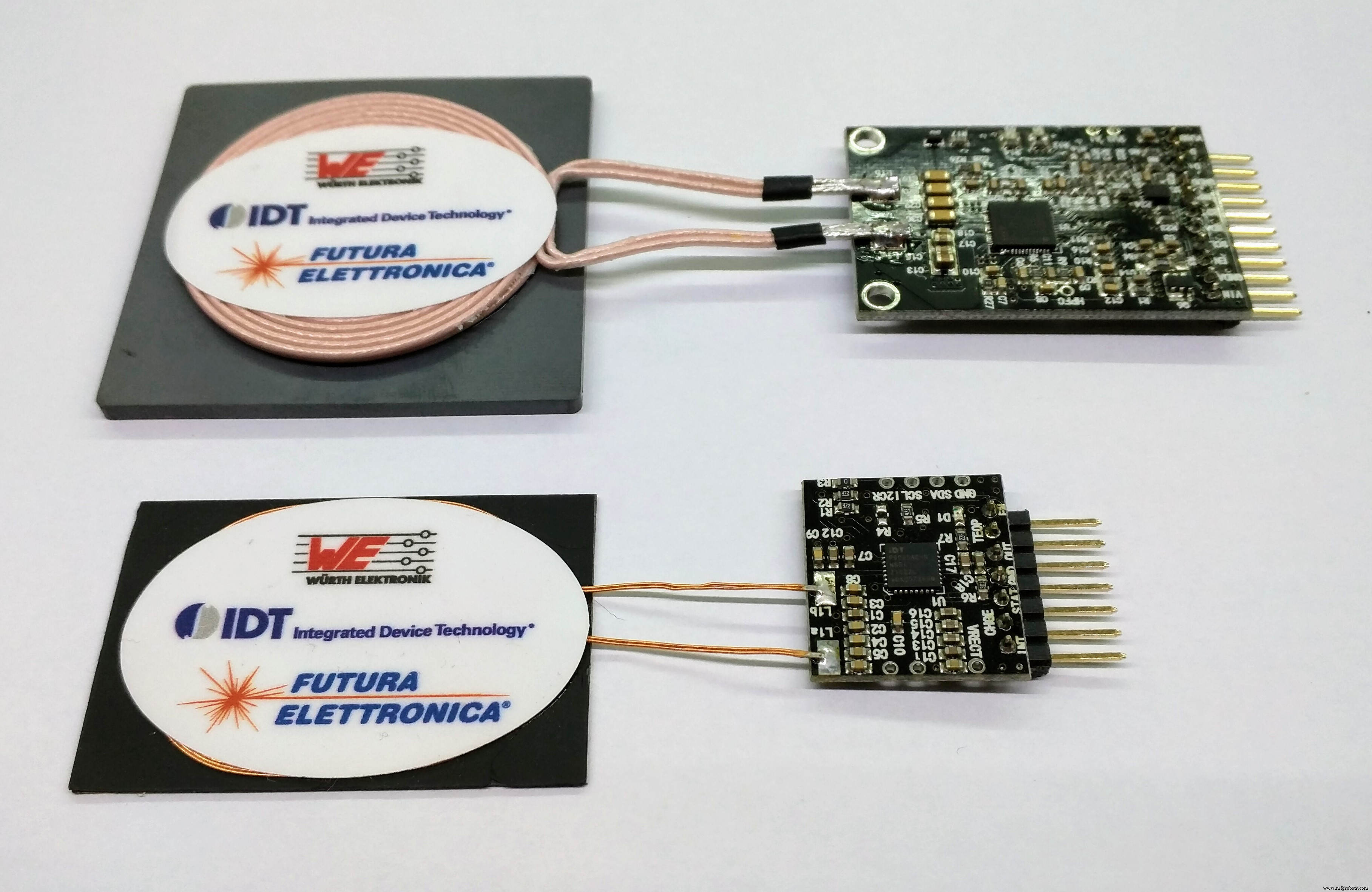
To use the receiver and transmitter, it's just a simple matter of providing the specified voltage to the transmitter. That will be the 'dock', where you can place Alzheimer's Assistant to charge. At the receiver side, you will just have to cut and attach a spare USB micro B cable (which goes to the MKR1000 USB port) and connect the other side to VCC and ground by looking at the pinout.
Just look at the images below to see how to wire it up:
<図>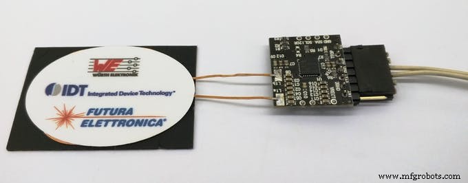 <図>
<図> 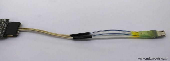 <図>
<図> 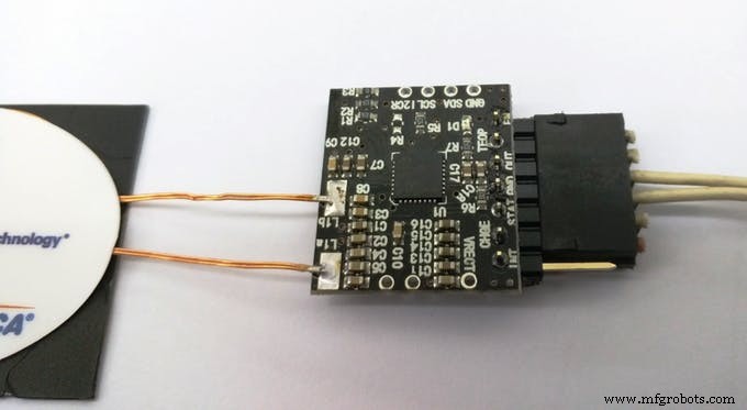 <図>
<図> 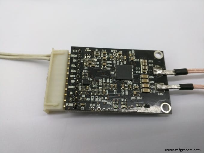 <図>
<図> 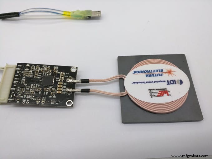 <図>
<図> 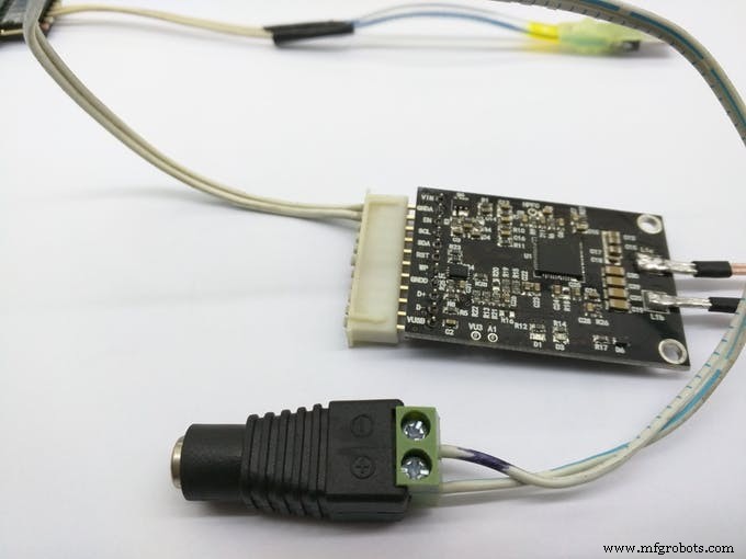
And the end result:
<図>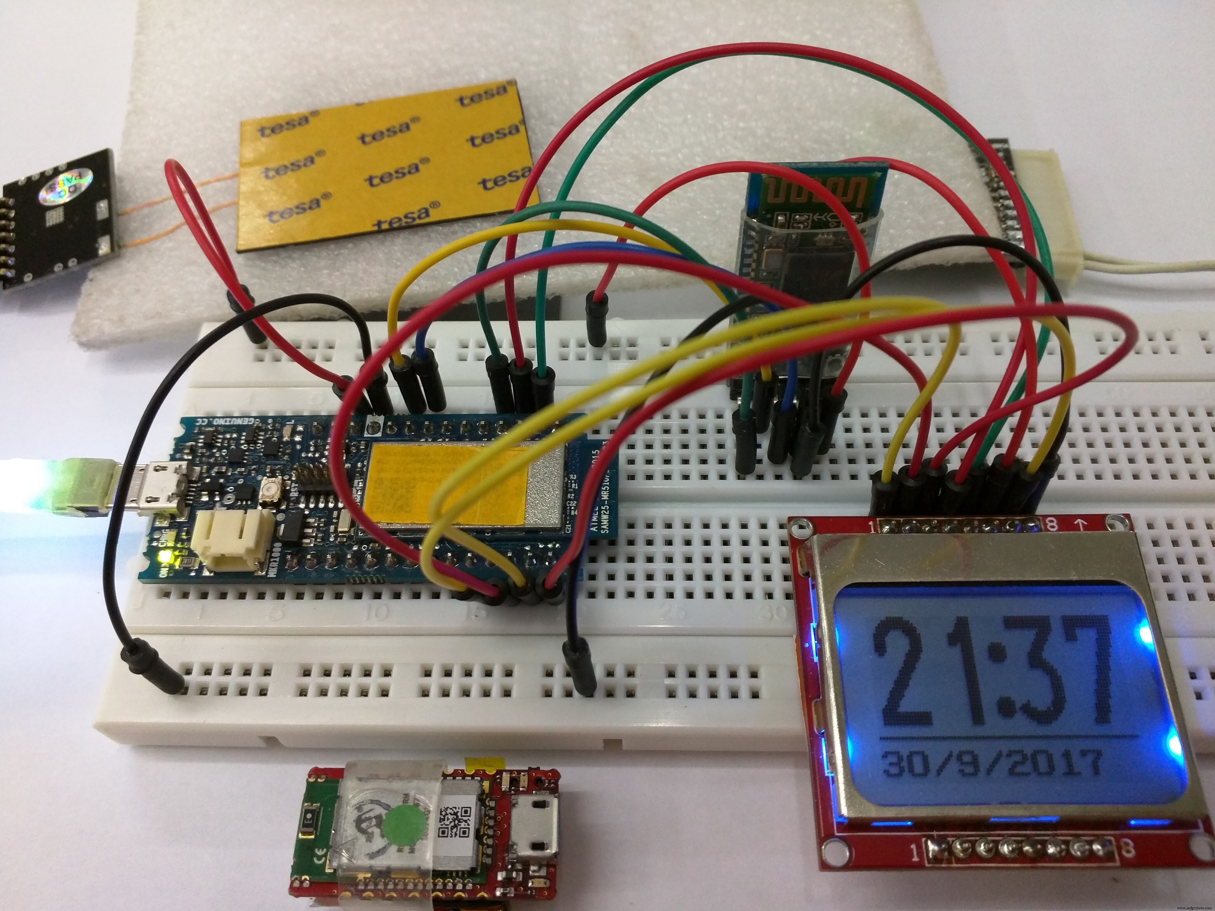
The Enclosure:
As with every project, an enclosure is required for this too, and this how I intend Alzheimer's Assistant to look like:
<図>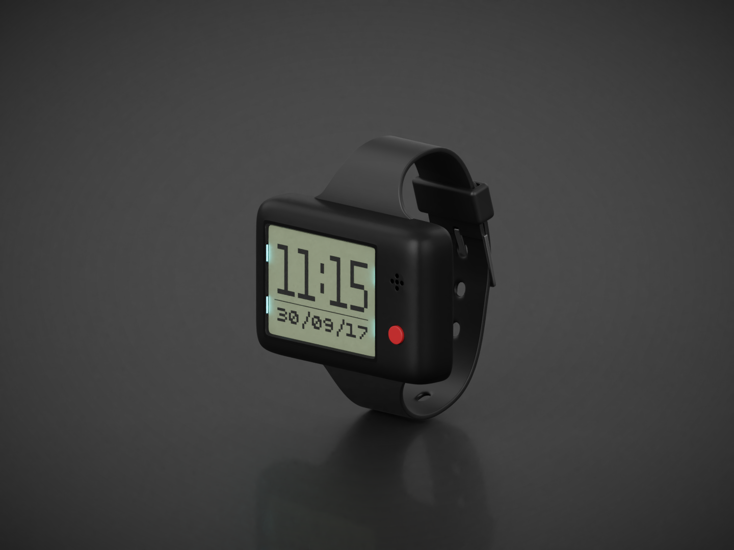
Note:I do not yet have the privilege of a laser cutter or 3D printer, so the STL file is just intended for showing how the final project looks like and it's not to scale.
This concludes the documentation for Alzheimer's Assistant, but I would still like to include the future work section to describe the things which I very much wanted to do for the project, but couldn't, due to some reason or the other.
Future work:
As I said before, these are the things which I wanted to include in the project, which I will add in future, should I get the time:
- Making a proper enclosure for it. Now I am just testing it on a breadboard but if I get access to a laser cutter or 3D printer I will update the documentation with that.
- Using a Bluetooth 4.0 module instead of this one.
- Or even better, using just the DPS310 Sensor instead of the Sensor Hub Nano. This would decrease the cost for the project overall, as it will eliminate the use of the Sensor Hub Nano and the bluetooth module; the DPS310 itself is a available for cheap. It's a matter of editing the main code to get temperature, pressure and altitude values from the DPS310 only, the rest of the part is done.
- Using a secondary sensor to work along with the DPS310 for fall detection and the location detection. This would decrease the occurrence of both, false positive and false negative alerts. Most probably an accelerometer and a motion detector will be needed for both.
- Adding a pulse sensor. I did not have one, so I couldn't add that. It should be a great addition to the project.
- Using a higher resolution display, preferably an OLED. With that, graphics can also be included and that would be pretty neat.
- Working on improving the battery life for the project. This can be done by using a deep sleep mode in the MKR1000, but I haven't used it in the code yet.
Thanks for reading, and hope you liked my project. Feel free to give me your opinions and ideas about the project.
コード
- AT Commands
- Alzheimer's Assistant
AT CommandsArduino
This code is used to configure the HC-05 in AT mode. Details on how to get in AT mode are given in the project description// Original sketch from Martyn Currey's blog here:// http://www.martyncurrey.com/arduino-with-hc-05-bluetooth-module-at-mode///// Sketch modified by me to work with Arduino MKR1000!//// Basic Bluetooth sketch// Connect the HC-05 module and communicate using the serial monitor//// The HC-05 defaults to commincation mode when first powered on.// Needs to be placed in to AT mode// After a factory reset the default baud rate for communication mode is 38400char c =' ';void setup() { // start the serial communication with the host computer Serial.begin(9600); Serial.println("Arduino with HC-05 is ready"); // start communication with the HC-05 using 38400 Serial1.begin(38400); Serial.println("Serial1 started at 38400");}void loop() { // Keep reading from HC-05 and send to Arduino Serial Monitor if (Serial1.available()) { c =Serial1.read(); Serial.write(c); } // Keep reading from Arduino Serial Monitor and send to HC-05 if (Serial.available()) { c =Serial.read(); // mirror the commands back to the serial monitor // makes it easy to follow the commands Serial.write(c); Serial1.write(c); }} Alzheimer's AssistantArduino
The main code for the project, used once you've configured and got the HC-05 to work with Sensor Hub Nano//Including required libraries#include#include #include #include #include #include // You should get Auth Token in the Blynk App.// Go to the Project Settings (nut icon).char auth[] =""; //Enter your Blynk auth token here// Your WiFi credentials.// Set password to "" for open networks.char ssid[] ="";char pass[] ="";//Defining Sensor Hub Nano board commands#define HELLO "$hello id="#define INFO "$info id="#define SENSOR_INFO "$sinfo id=1"#define LOW_ENERGY "$set_mode sid=1;md=mode;val=bg"#define STANDARD_MODE "$set_mode sid=1;md=prs_osr;val=16"#define HIGH_PRECISION "$set_mode sid=1;md=prs_mr;val=32"#define START "$start_sensor id=1"#define STOP "$stop id="//Defining fall and clearance thresholds//You may need to change them, but I found these values to be good#define FALL 0.7#define CLEARANCE 0.2//Defining Blynk virtual pins#define vTEMPERATURE_PIN V0#define vPRESSURE_PIN V1#define vALTITUDE_PIN V2#define vEVENTOR_PIN V3#define vFALL_PIN V4//Declaring required variablesfloat t, p, a, previousA;//Boolean which tells tells if a fall is detected or notboolean fallState;//Variables needed for the fall detection algorithmunsigned long previousMillis =0;const l ong interval =1000;//BTconnected is false when not connected and true when connectedboolean BTconnected =false;//Defining BT state and LCD backlight pinsint btStatePin =9;int backlightPin =2;BlynkTimer timer;WidgetRTC rtc;//Nokia 5110 Display wiringU8G2_PCD8544_84X48_F_4W_SW_SPI u8g2(U8G2_R0, /* clock=*/ 7, /* data=*/ 8, /* cs=*/ 3, /* dc=*/ 5, /* reset=*/ 4);void setup() { //Initialize both serial ports:Serial.begin(115200); Serial1.begin(115200); //Setup the timed fuctions timer.setInterval(1000L, sendSensorValues); timer.setInterval(3000L, showTimeAndDate); //Setting up required inputs and outputs pinMode(btStatePin, INPUT); pinMode(backlightPin, OUTPUT); digitalWrite(backlightPin, LOW); u8g2.begin(); showStartMessage(); delay(2000); // wait until the bluetooth module has made a connection while (!BTconnected) { if (digitalRead(btStatePin) ==HIGH) { BTconnected =true; } else { showWaitingFor(); } } initSensorHub(); Blynk.begin(auth, ssid, pass); rtc.begin(); setBlynkWidgets(); showTimeAndDate(); sendCommand(START);}void loop() { Blynk.run(); timer.run(); getSensorValues(); checkIfFalling();}void sendCommand (String sensorCommand) { //This function sends commands through the bluetooth module on the hardware serial port to the the Sensor Hub Nano //For example:"sendCommand(START);", starts the flow of data from the sensor //The full list of commands I know are defined at the top of the sketch Serial1.println(sensorCommand);}void initSensorHub() { //Initialise the Sensor Hub Nano, and give an error if there is any problem String junkVal; sendCommand(INFO); while (Serial1.find("IFX_NanoHub") ==false) { sendCommand(INFO); Serial.println("ERROR"); showErrorMessage(); } junkVal =Serial1.readStringUntil('\n'); junkVal =""; showConnectedMessage(); delay(1500);}void getSensorValues() { //Retrieves the sensor values from the Sensor Hub Nano through the Serial1 port String junkVal; if (Serial1.available()) { junkVal =Serial1.readStringUntil('\n'); junkVal =Serial1.readStringUntil('t'); t =Serial1.parseFloat(); junkVal =Serial1.readStringUntil('p'); p =Serial1.parseFloat(); junkVal =Serial1.readStringUntil('a'); a =Serial1.parseFloat(); junkVal =Serial1.readStringUntil('\n'); }}void sendSensorValues() { //Sending the sensor values to the Blynk server Blynk.virtualWrite(vTEMPERATURE_PIN, t); Blynk.virtualWrite(vPRESSURE_PIN, p); Blynk.virtualWrite(vALTITUDE_PIN, a);}void checkIfFalling() { //Algorithm to check if the patient is falling unsigned long currentMillis =millis(); if ((currentMillis - previousMillis)>=interval) { float diff =previousA - a; if ((diff>=(FALL - CLEARANCE)) &&(diff <=(FALL + CLEARANCE))) { fallState =true; //Here insert what you need to do if fall is detected, such as sending a notification or email with Blynk //Or you could also use IFTTT to call or send an sms to alert the caretaker (more info in the project documentation) Serial.println("Falling"); showFallMessage(); //In this example, vFALL_PIN (virtual pin 4) is set to 255 if fall is detected Blynk.virtualWrite(vFALL_PIN, 255); //You can send a notification using only the notification widget too! //Blynk.notify("DPS310 detected a fall!"); } previousA =a; previousMillis =currentMillis; fallState =false; //Set vFALL_PIN to 0 if a fall isn't detected Blynk.virtualWrite(vFALL_PIN, 0); }}void showStartMessage() { //Shows the start-up message u8g2.clearBuffer(); u8g2.drawRFrame(3, 7, 75, 31, 7); u8g2.setFont(u8g2_font_prospero_bold_nbp_tf); u8g2.drawStr(8, 19, "Alzheimer's"); u8g2.drawStr(12, 35, "Assistant"); u8g2.sendBuffer();}void showWaitingFor() { //Shows the waiting for Sensor Hub Nano message u8g2.clearBuffer(); u8g2.setFont(u8g2_font_prospero_bold_nbp_tf); u8g2.drawStr(9, 15, "Waiting for"); u8g2.drawStr(8, 28, "Sensor Hub"); u8g2.drawStr(22, 41, "Nano !!!"); u8g2.sendBuffer();}void showConnectedMessage() { //Shows the connected message u8g2.clearBuffer(); u8g2.setFont(u8g2_font_7x13B_tf); u8g2.drawStr(0, 10, "Connected to"); u8g2.drawStr(8, 22, "Infineon's"); u8g2.drawStr(7, 34, "Sensor Hub"); u8g2.drawStr(29, 46, "Nano"); u8g2.sendBuffer();}void showErrorMessage() { //Shows the error message u8g2.clearBuffer(); // clear the internal memory u8g2.setFont(u8g2_font_fub14_tf); // choose a suitable font u8g2.drawStr(9, 30, "ERROR"); // write something to the internal memory u8g2.sendBuffer(); // transfer internal memory to the display}void showSensorValues() { //Shows the sensor values on the display char bufT[10]; char bufP[10]; char bufA[10]; String(t).toCharArray(bufT, 10); String(p).toCharArray(bufP, 10); String(a).toCharArray(bufA, 10); u8g2.clearBuffer(); u8g2.setFont(u8g2_font_6x10_tf ); //Display the temperature u8g2.drawStr(0, 10, "T:"); u8g2.drawStr(12, 10, bufT); u8g2.drawStr(73, 10, "C"); u8g2.drawCircle(70, 4, 1, U8G2_DRAW_ALL); u8g2.drawHLine(0, 12, 85); //Display the pressure u8g2.drawStr(0, 26, "P:"); u8g2.drawStr(12, 26, bufP); u8g2.drawStr(60, 26, "mBar"); u8g2.drawHLine(0, 28, 85); //Display the altitude u8g2.drawStr(0, 42, "A:"); u8g2.drawStr(12, 42, bufA); u8g2.drawStr(72, 42, "m"); u8g2.drawHLine(0, 44, 85); //Send the values to the display u8g2.sendBuffer();}void showFallMessage() { //Show the fall detected message u8g2.clearBuffer(); u8g2.setFont(u8g2_font_7x13B_tf); u8g2.drawStr(27, 20, "Fall"); u8g2.drawStr(13, 32, "Detected!"); u8g2.sendBuffer(); delay(1000);}void showPillReminder() { //Show the pill reminder message u8g2.clearBuffer(); u8g2.setFont(u8g2_font_7x13B_tf); u8g2.drawStr(0, 20, "Time to take"); u8g2.drawStr(5, 32, "your pills!"); u8g2.sendBuffer();}void showExerciseReminder() { //Show the exercise reminder message u8g2.clearBuffer(); u8g2.setFont(u8g2_font_7x13B_tf); u8g2.drawStr(16, 20, "Time to"); u8g2.drawStr(12, 32, "exercise!"); u8g2.sendBuffer();}void showTimeAndDate() { //Displays the time and date from the RTC widget in Blynk in 24 hours format if (year() ==1970) { //Serial.println("Time not yet synced"); } else if (year() !=1970) { char bufHours[3]; char bufColon[2]; char bufMinutes[3]; char bufDate[11]; String currentHours =String(hour()); String colon =":"; String currentMinutes =String(minute()); String currentDate =String(day()) + "/" + month() + "/" + year(); String(currentHours).toCharArray(bufHours, 3); String(colon).toCharArray(bufColon, 2); String(currentMinutes).toCharArray(bufMinutes, 3); String(currentDate).toCharArray(bufDate, 11); u8g2.clearBuffer(); u8g2.setFont(u8g2_font_inr33_mf); u8g2.drawStr(30, 30, bufColon); u8g2.setFont(u8g2_font_logisoso32_tn); u8g2.drawStr(0, 32, bufHours); u8g2.drawStr(45, 32, bufMinutes); u8g2.setFont(u8g2_font_saikyosansbold8_8n); u8g2.drawHLine(0, 35, 85); u8g2.drawStr(0, 46, bufDate); u8g2.sendBuffer(); }}BLYNK_WRITE(vEVENTOR_PIN) { //Use the Eventor widget to check if it's time to do a task (take medication in this case) int currentValue =param.asInt(); // 0 to 1 if (currentValue ==1) { showPillReminder(); //Serial.println("Time to take your pills"); } else { //Serial.println("Not the time to take pills"); }}void setBlynkWidgets() { //This sets the colour of each widget in the Blynk app //You may remove this from the sketch if you want to set colours manually through the Blynk app //You could also specifiy the hex value of each colour you need //Set temperature widget color to white Blynk.setProperty(vTEMPERATURE_PIN, "color", "#FFFFFF"); //Set pressure widget color to blue Blynk.setProperty(vPRESSURE_PIN, "color", "#00BBFF"); //Set altitude widget color to yellow Blynk.setProperty(vALTITUDE_PIN, "color", "#FFFF00");}BLYNK_CONNECTED() { //Synchronize time on connection, if connection drops rtc.begin();}
カスタムパーツとエンクロージャー
This is just to show how I intend the enclosure to look like. It's not at all to scale! 回路図
This diagram is used when getting your HC-05 in AT mode and configuring it, using the Arduino MKR1000.  Fritzing diagram for the bare-bones project to function
 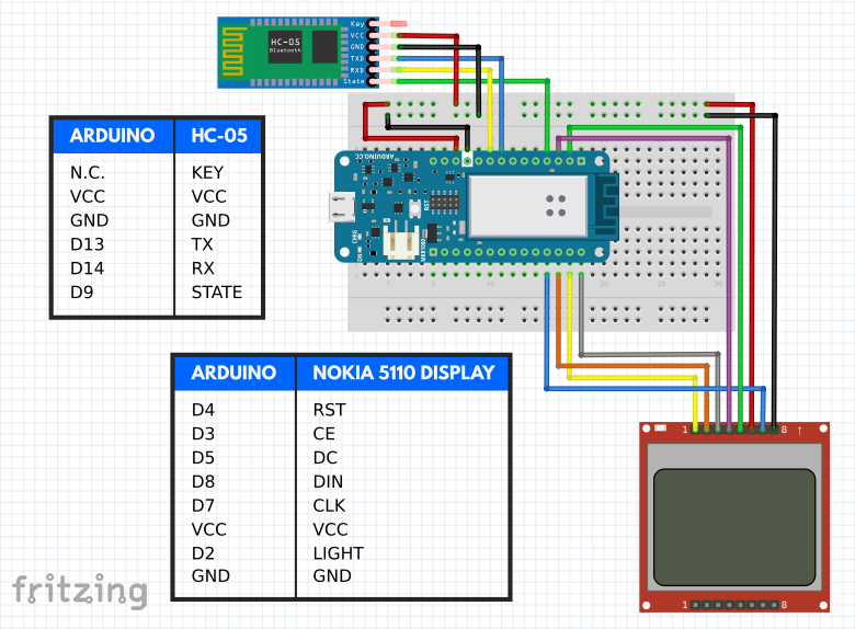 Document listing AT commands for the HC-05
製造プロセス