


Verilog の割り当てステートメント
タイプ wire のシグナル または同様のワイヤのようなデータ型では、値を連続して割り当てる必要があります。たとえば、ブレッドボード上の部品を接続するために使用される電線を考えてみましょう。 +5V バッテリーがワイヤの一方の端に接続されている限り、ワイヤのもう一方の端に接続されたコンポーネントは必要な電圧を取得します。

Verilog では、この概念は assign によって実現されます。 ステートメント where any wire または他の同様のワイヤのようなデータ型は、値で連続的に駆動できます。値は、定数またはシグナルのグループで構成される式のいずれかです。
構文を割り当てる
代入構文はキーワード assign で始まります 信号名は、単一の信号または異なる信号ネットの連結のいずれかです。 駆動力 そして遅延 オプションであり、実際のハードウェアに合成するよりもデータフロー モデリングに主に使用されます。右側の式または信号が評価され、左側のネットまたはネットの式に割り当てられます。
assign <net_expression> = [drive_strength] [delay] <expression of different signals or constant value>
遅延値は、ゲートの遅延を指定するのに役立ち、実際のハードウェアでタイミング動作をモデル化するために使用されます。これは、評価された値をネットにいつ割り当てるかが値によって決まるためです。
ルール
assign を使用する場合に従う必要があるルールがいくつかあります。 ステートメント:
- LHS は常にスカラーまたはベクター ネット、またはスカラーまたはベクター ネットの連結である必要があり、スカラーまたはベクター レジスタであってはなりません。
- RHS には、スカラーまたはベクトル レジスタと関数呼び出しを含めることができます。
- RHS のオペランドの値が変更されるたびに、LHS は新しい値で更新されます。
assignステートメントは連続割り当てとも呼ばれ、常にアクティブです
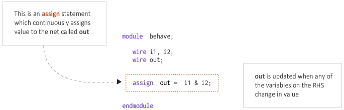
例 #1
次の例では、呼び出されたネットが信号の式によって連続的に駆動されます。論理 AND & を使用した i1 と i2 式を形成します。
代わりにワイヤをポートに変換して合成すると、合成後に以下に示すような RTL 回路図が得られます。
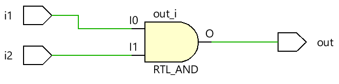
連続代入文は、Verilog で組み合わせゲートを表すために使用できます。
例 #2
以下に示すモジュールは、2 つの入力を取り、assign を使用します。 部分選択と複数のビット連結を使用して出力 z を駆動するステートメント。各ケースをモジュール内の唯一のコードとして扱い、そうでなければ多くの assign を扱います 同じ信号に対するステートメントは、間違いなく出力を X にします。
module xyz (input [3:0] 	x,		// x is a 4-bit vector net
						input 				y, 		// y is a scalar net (1-bit)
						output [4:0] 	z ); 	// z is a 5-bit vector net

wire [1:0] 	a;
wire 				b;

// Assume one of the following assignments are chosen in real design
// If x='hC and y='h1 let us see the value of z

// Case #1: 4-bits of x and 1 bit of y is concatenated to get a 5-bit net
// and is assigned to the 5-bit nets of z. So value of z='b11001 or z='h19
assign z = {x, y};

// Case #2: 4-bits of x and 1 bit of y is concatenated to get a 5-bit net
// and is assigned to selected 3-bits of net z. Remaining 2 bits of z remains
// undriven and will be high-imp. So value of z='bZ001Z
assign z[3:1] = {x, y};

// Case #3: The same statement is used but now bit4 of z is driven with a constant
// value of 1. Now z = 'b1001Z because only bit0 remains undriven
assign z[3:1] = {x, y};
assign z[4] = 1;

// Case #4: Assume bit3 is driven instead, but now there are two drivers for bit3,
// and both are driving the same value of 0. So there should be no contention and
// value of z = 'bZ001Z
assign z[3:1] = {x, y};
assign z[3] = 0;

// Case #5: Assume bit3 is instead driven with value 1, so now there are two drivers
// with different values, where the first line is driven with the value of X which
// at the time is 0 and the second assignment where it is driven with value 1, so
// now it becomes unknown which will win. So z='bZX01Z
assign z[3:1] = {x, y};
assign z[3] = 1;

// Case #6: Partial selection of operands on RHS is also possible and say only 2-bits
// are chosen from x, then z = 'b00001 because z[4:3] will be driven with 0
assign z = {x[1:0], y};

// Case #7: Say we explicitly assign only 3-bits of z and leave remaining unconnected
// then z = 'bZZ001
assign z[2:0] = {x[1:0], y};

// Case #8: Same variable can be used multiple times as well and z = 'b00111
// 3{y} is the same as {y, y, y}
assign z = {3{y}};

// Case #9: LHS can also be concatenated: a is 2-bit vector and b is scalar
// RHS is evaluated to 11001 and LHS is 3-bit wide so first 3 bits from LSB of RHS
// will be assigned to LHS. So a = 'b00 and b ='b1
assign {a, b} = {x, y};

// Case #10: If we reverse order on LHS keeping RHS same, we get a = 'b01 and b='b0
assign {a, b} = {x, y};

endmodule
reg 変数を割り当てる
reg を駆動または割り当てることは違法です assign で変数を入力します 声明。これは reg 変数はデータを格納でき、連続的に駆動する必要はありません。 reg 信号は initial のような手続き型ブロックでのみ駆動できます と always .
暗黙の連続代入
assign の場合 ステートメントは、指定されたネットに何らかの値を割り当てるために使用され、explicit と呼ばれます。 割り当て。 Verilog では、ネットが宣言され、implicit と呼ばれる場合に割り当てを行うこともできます。
wire [1:0] a;
assign a = x & y; 			// Explicit assignment

wire [1:0] a = x & y; 	// Implicit assignment
組み合わせ論理設計
組み合わせゲートと対応する Verilog コードから作成された次のデジタル回路を検討してください。
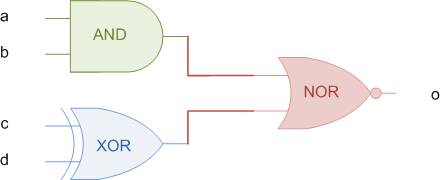
組み合わせロジックでは、クロックのエッジで値がキャプチャされて格納されるフリップフロップなどのシーケンシャル エレメントとは異なり、出力を維持するために入力を継続的に駆動する必要があります。だから assign 右側の入力のいずれかが変更されるたびに出力 o が更新されるため、このステートメントは目的に適しています。
// This module takes four inputs and performs a boolean
// operation and assigns output to o. The combinational
// logic is realized using assign statement.
module combo ( input a, b, c, d,
output o);
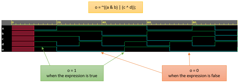
assign o = ~((a & b) | c ^ d);
endmodule
ハードウェア回路図
設計の精緻化と合成の後、assign によってモデル化されたのと同じように動作する組み合わせ回路を見ることができます。
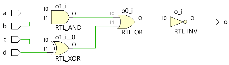
RHS の組み合わせ式が真になるたびに、信号 o が 1 になることを確認します。同様に、RHS が false の場合、o は 0 になります。入力が同時に X であるため、出力 o は 0ns から 10ns まで X です。
シミュレーション例のスライドショーはここをクリック!
Verilog