


Verilog モジュールのインスタンス化
以前の記事で説明したように、より大規模で複雑な設計は、複数のモジュールを階層的に統合することによって構築されます。モジュールはインスタンス化できます これらのインスタンスの他のモジュールおよびポート内 親モジュール内の他の信号と接続できます。
これらのポート接続は、番号付きリストまたは名前で行うことができます。
番号付きリストによるポート接続
モジュールのインスタンス化にリストされているポート式と親モジュール内のシグナルとを関連付ける方法の 1 つは、順序付けられたリストを使用することです。 .
mydesign は module です tb_top という別のモジュールで d0 という名前でインスタンス化されます。ポートは、モジュール宣言のポート リスト内のそのポートの位置によって決定される特定の順序で接続されます。たとえば、テストベンチの b は、両方ともポート リストの 2 番目の位置にあるという理由だけで、設計の y に接続されます。
	module mydesign ( input  x, y, z,     // x is at position 1, y at 2, x at 3 and
	                  output o);          // o is at position 4

	endmodule

	module tb_top;
		wire [1:0]  a;
		wire        b, c;

		mydesign d0  (a[0], b, a[1], c);  // a[0] is at position 1 so it is automatically connected to x
		                                  // b is at position 2 so it is automatically connected to y
		                                  // a[1] is at position 3 so it is connected to z
		                                  // c is at position 4, and hence connection is with o
	endmodule
正しく接続するには、設計モジュール内のポートの順序がわかっている必要があります。
新しいポートがリストに追加された場合、または設計内のポートの数が非常に多い場合、順序が変更される可能性があるため、これは非常に不便です.
名前によるポート接続
ポートを接続するより良い方法は、ポート名を使用して両側のポートを明示的にリンクすることです .
ドット . ドットに続くポート名がデザインに属することを示します。デザイン ポートを接続する必要がある信号名は、括弧 ( ) 内に次に指定されます。 .
module design_top;
	wire [1:0]  a;
	wire        b, c;

	mydesign d0  ( .x (a[0]),    // signal "x" in mydesign should be connected to "a[0]" in this module (design_top)
	               .y (b),       // signal "y" in mydesign should be connected to "b" in this module (design_top)
	               .z (a[1]),
	               .o (c));
endmodule
各ポート接続を個別の行にコーディングして、コンパイル エラー メッセージがエラーが発生した行番号を正しく指すようにすることをお勧めします。これは、すべてが同じ行にある場合にどのポートでエラーが発生したかがわからない場合に比べて、デバッグと解決がはるかに簡単です。
これらの接続は名前で作成されるため、表示される順序は関係ありません。複数のモジュール インスタンス ポート接続は許可されていません。
	module design_top;
		mydesign d0 ( .x (a[0]),
		              .z (a[1]),     // z at second position is okay because of explicit connection
		              .y (a[1]),
		              .x (b),        // illegal - x is already connected to a[0]
		              .o (c));
	endmodule
未接続/フローティング ポート
インスタンス化モジュールのどのワイヤにも接続されていないポートは、高インピーダンスの値になります。
module design_top;
	mydesign d0   (              // x is an input and not connected, hence a[0] will be Z
	              .y (a[1]),
	              .z (a[1]),
	              .o ());        // o has valid value in mydesign but since
	                             // it is not connected to "c" in design_top, c will be Z
endmodule
例
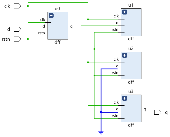
前に見たシフト レジスタの例を見てみましょう。いくつかのポートは接続されていません。
module shift_reg (   input   d,
                    input    clk,
                    input   rstn,
                    output   q);

  wire [2:0] q_net;

  dff u0 (.d(d),         .clk(clk), .rstn(rstn), .q(q_net[0]));
  dff u1 (.d(q_net[0]), .clk(clk), .rstn(rstn), .q()); 						// Output q is left floating
  dff u2 (.d(q_net[1]), .clk(clk), .rstn(rstn), .q()); 						// Output q is left floating
  dff u3 (.d(q_net[2]), .clk(clk), .rstn(rstn), .q(q));

endmodule
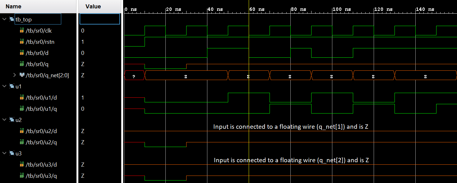
インスタンス u1 および u2 からの出力は、合成後に得られる RTL 回路図では未接続のままであることに注意してください。インスタンス u2 および u3 への入力 d は、何も駆動されていないネットに接続されているため、接地されています。
シミュレーションでは、このような接続されていないポートは高インピーダンス ('hZ) として示され、通常は中央に垂直に配置されたオレンジ色の線として波形に示されます。
すべてのポート宣言は暗黙的に wire として宣言されます したがって、その場合はポート方向で十分です。ただし output 値を格納する必要があるポートは reg として宣言する必要があります always のような手続き型ブロックで使用できます。 そして initial
タイプ input のポート または inout reg として宣言することはできません これらは外部から継続的に駆動されており、値を保存するのではなく、できるだけ早く外部信号の変化を反映する必要があるためです。ベクトル サイズが異なる 2 つのポートを接続することは完全に合法ですが、ベクトル サイズが小さいポートが優先され、幅が大きいポートの残りのビットは無視されます。
	// Case #1 : Inputs are by default implicitly declared as type "wire"
	module des0_1	(input wire clk ...); 		// wire need not be specified here
	module des0_2 	(input clk, ...); 			// By default clk is of type wire

	// Case #2 : Inputs cannot be of type reg
	module des1 (input reg clk, ...); 		// Illegal: inputs cannot be of type reg

	// Case #3: Take two modules here with varying port widths
	module des2 (output [3:0] data, ...);	// A module declaration with 4-bit vector as output
	module des3 (input [7:0] data, ...); 	// A module declaration with 8-bit vector as input

	module top ( ... );
		wire [7:0] net;
		des2  u0 ( .data(net) ... ); 		// Upper 4-bits of net are undriven
		des3  u1 ( .data(net) ... );
	endmodule

	// Case #4 : Outputs cannot be connected to reg in parent module
	module top_0 ( ... );
		reg [3:0] data_reg;

		des2 ( .data(data) ...); 	// Illegal: data output port is connected to a reg type signal "data_reg"
	endmodule
Verilog