



ArduinoとOpenCVで作るリアルタイム顔追跡システム
必要な部品と材料
| 部品 | 数量 | 備考 |
|---|---|---|
| Arduino UNO | 1 | 他ボードでも可 |
| Webカメラ | 1 | ミニサイズ推奨 |
| マイクロサーボ | 2 | 標準サーボでも可 |
| パンチルトキット | 1 | 自作・3Dプリントも可 |
| ブレッドボード | 1 |
使用アプリ・オンラインサービス
- Python 2.7
- OpenCV(
pip install opencv-python) - pyserial(
pip install pyserial) - numpy(
pip install numpy) - Haarcascade分類器(
haarcascade_frontalface_default.xml)
プロジェクト概要
前回のチュートリアル(Arduino-Pythonシリアル通信、OpenCV色追跡)に続き、今回は顔検出・追跡を行い、カメラを顔に追従させます。ArduinoとPythonの基礎知識があれば誰でも作れます。
ステップ1:必要なもの
ハードウェア・ソフトウェア要件は上記の通り。全ファイルを同一フォルダに配置してください。
ステップ2:Python環境構築
- Python 2.7.14をインストール(環境変数PATH設定必須)
- コマンドプロンプトで以下実行:
> pip install serial
> pip install opencv-python
> pip install numpy
ステップ3:Pythonスクリプト(face.py)
Haarcascade XMLファイルを同フォルダに置き、以下のスクリプトをface.pyとして保存。
import numpy as np
import serial, time, sys, cv2

# Arduino接続ポートを指定(環境に合わせて変更)
arduino = serial.Serial('COM5', 9600)
time.sleep(2)
print("Connected to arduino...")

# 顔検出分類器読み込み
face_cascade = cv2.CascadeClassifier('haarcascade_frontalface_default.xml')

# Webカメラキャプチャ開始
cap = cv2.VideoCapture(0)

while True:
    ret, img = cap.read()
    cv2.resizeWindow('img', 500, 500)
    # 画面中心線と中心点描画
    cv2.line(img, (500, 250), (0, 250), (0, 255, 0), 1)
    cv2.line(img, (250, 0), (250, 500), (0, 255, 0), 1)
    cv2.circle(img, (250, 250), 5, (255, 255, 255), -1)

    gray = cv2.cvtColor(img, cv2.COLOR_BGR2GRAY)
    faces = face_cascade.detectMultiScale(gray, 1.3)

    for (x, y, w, h) in faces:
        cv2.rectangle(img, (x, y), (x+w, y+h), (0, 255, 0), 5)
        # 矩形中心座標計算
        xx = int(x + (x + w)) / 2
        yy = int(y + (y + h)) / 2
        center = (xx, yy)
        print("Center of Rectangle is:", center)

        # Arduinoへ送信: "X{center_x}Y{center_y}Z"
        data = "X{0:d}Y{1:d}Z".format(xx, yy)
        print("output = '" + data + "'")
        arduino.write(data.encode())

    cv2.imshow('img', img)
    # ESCキーで終了
    if cv2.waitKey(30) & 0xff == 27:
        break

cap.release()
cv2.destroyAllWindows()
ステップ4:Arduinoスケッチ(servo.ino)
#include <Servo.h>
Servo servoVer;  // 垂直サーボ
Servo servoHor;  // 水平サーボ
int x, y, prevX, prevY;

void setup() {
  Serial.begin(9600);
  servoVer.attach(5);  // 垂直:ピン5
  servoHor.attach(6);  // 水平:ピン6
  servoVer.write(90);
  servoHor.write(90);
}

void updatePosition() {
  if (prevX != x || prevY != y) {
    // カメラ座標(600×450)をサーボ角度にマッピング
    int servoX = map(x, 600, 0, 70, 179);
    int servoY = map(y, 450, 0, 179, 95);
    servoX = constrain(servoX, 70, 179);
    servoY = constrain(servoY, 95, 179);
    servoHor.write(servoX);
    servoVer.write(servoY);
    prevX = x; prevY = y;
  }
}

void loop() {
  if (Serial.available() > 0) {
    if (Serial.read() == 'X') {
      x = Serial.parseInt();
      if (Serial.read() == 'Y') {
        y = Serial.parseInt();
        updatePosition();
      }
    }
    while (Serial.available() > 0) Serial.read(); // バッファクリア
  }
}
ステップ5:パンチルト機構
市販キットを使用(安価で組立簡単)。自作も可能(木材/プラスチック/3Dプリント)。
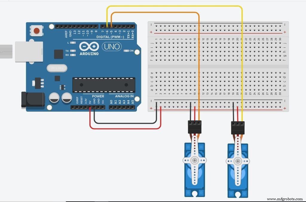
ステップ6:配線
- 垂直サーボ → ピン5
- 水平サーボ → ピン6
- 電源 → 5V / GND
ステップ7:テスト
- サーボ配線確認後、Arduinoスケッチ書き込み
- Arduino IDEを閉じてポート解放
- Python IDLEで
face.pyを開きF5実行 - カメラウィンドウが開き、顔検出・サーボ追従開始
- カメラをサーボに固定すれば、カメラ自体が顔を追跡
ダウンロードファイル
- haarcascade_frontalface_default.xml
- face.py
- servo.ino
製造プロセス
- Raspberry PiとPythonでリモート温度センサーを構築 – ステップバイステップガイド
- Raspberry Piでリアルタイム顔認識:エンドツーエンドガイド
- Raspberry PiとOpenCVによる自動ビジョンベース物体追跡
- ArduinoだけでDTMFデコーダーを構築 – 外付けIC不要
- Arduinoで作るモニター用Ambilightシステム:没入感アップの自作ガイド
- Python連携で信頼性向上: Arduino RFID勤怠管理システム
- Arduinoで超音波レベーション(浮遊)装置を自作:ステップバイステップガイド
- Arduinoとスマホで作るスマート電圧計 – 簡単DIYプロジェクト
- ArduinoとMAX30100で作るリアルタイムIoT心拍数モニター
- Arduino UNO WiFi Webサーバー:ブラウザからLEDをON/OFF制御
- Pythonで構築するIoT温度計: Zerynthによる完全ガイド