


ILI9341TFTタッチスクリーンディスプレイシールドのビットマップアニメーション
コンポーネントと消耗品
>  |
| × | 1 | |||
| × | 1 |
アプリとオンラインサービス
>  |
| |||
 |
|
このプロジェクトについて
ILI9341ベースのTFTタッチスクリーンディスプレイシールド 非常に人気のある低コストのディスプレイシールド Arduino の場合 。 Visuino かなり長い間サポートされてきましたが、使い方のチュートリアルを書く機会はありませんでした。ただし、最近、 Visuino でのディスプレイの使用について質問する人はほとんどいませんでした。 、それでチュートリアルを作ることにしました。
このチュートリアルでは、シールドを Arduino に接続するのがいかに簡単かを紹介します。 、 Visuino でプログラムします ビットマップをアニメーション化して、ディスプレイ上を移動します。
ステップ1:コンポーネント <図>
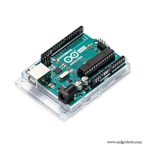
- 1つの Arduino Uno 互換性のあるボード(Megaでも動作する可能性がありますが、シールドはまだテストしていません)
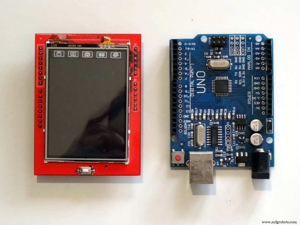
- Arduino用の ILI9341 2.4 "TFTタッチスクリーンシールド1つ
ステップ2:ILI9341TFTタッチスクリーンディスプレイシールドをArduinoに接続する <図>
 <図>
<図> 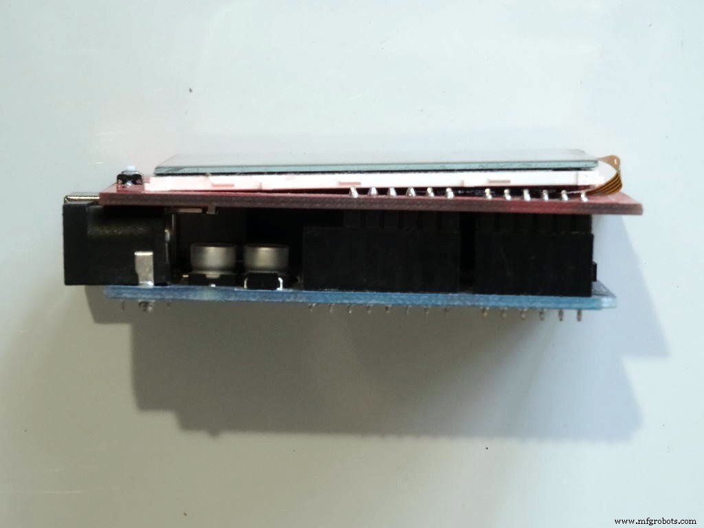 <図>
<図> 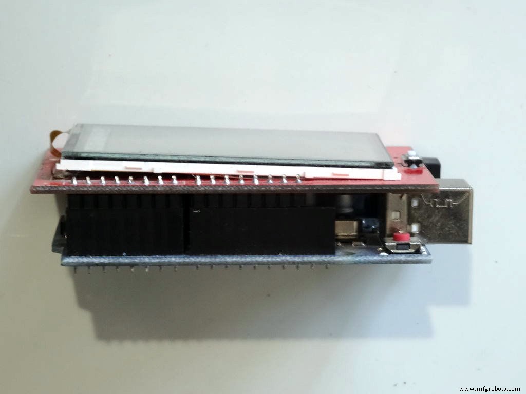
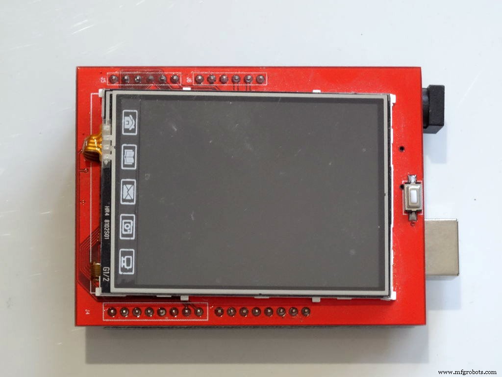
TFTシールドを接続します Arduino Uno の上に 写真に示されているように。
ステップ3:Visuinoを起動し、TFTディスプレイシールドを追加します <図>
 <図>
<図> 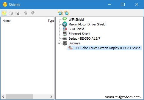
Arduinoのプログラミングを開始するには、 Arduino IDE が必要です。 ここからインストール:http://www.arduino.cc/。
必ず1.6.7以降をインストールしてください。インストールしないと、このチュートリアルは機能しません!
Visuino :https://www.visuino.comもインストールする必要があります。
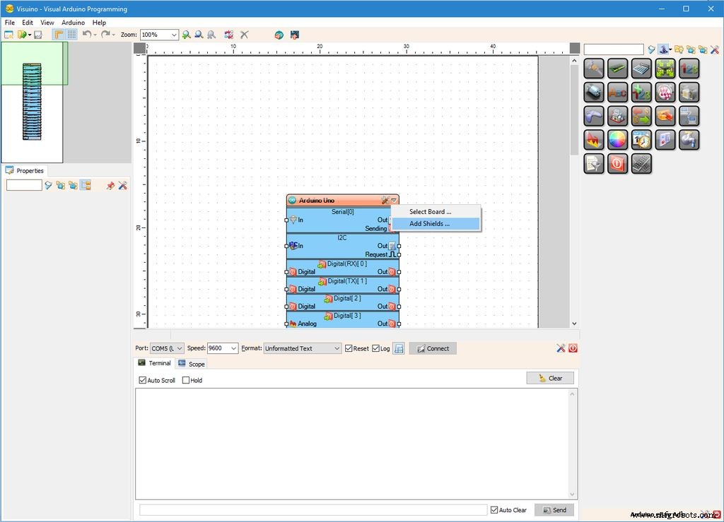
- Visuino を開始します 最初の写真に示されているように
- [下に矢印]をクリックします ドロップダウンメニューを開くためのArduinoコンポーネントのボタン(写真1 )
- メニューから[シールドを追加... ]を選択します "(写真1 )
- 「シールド」 []ダイアログで[ディスプレイ]を展開します 「」カテゴリをクリックし、「 TFTカラータッチスクリーンディスプレイILI9341シールド」を選択します。 "をクリックし、[ + ]をクリックします 追加するボタン(写真2 )
ステップ4:Visuinoの場合:テキストシャドウの描画テキスト要素を追加します <図>
 <図>
<図> 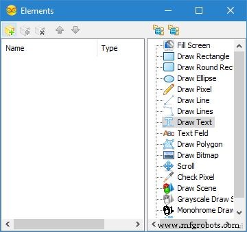 <図>
<図> 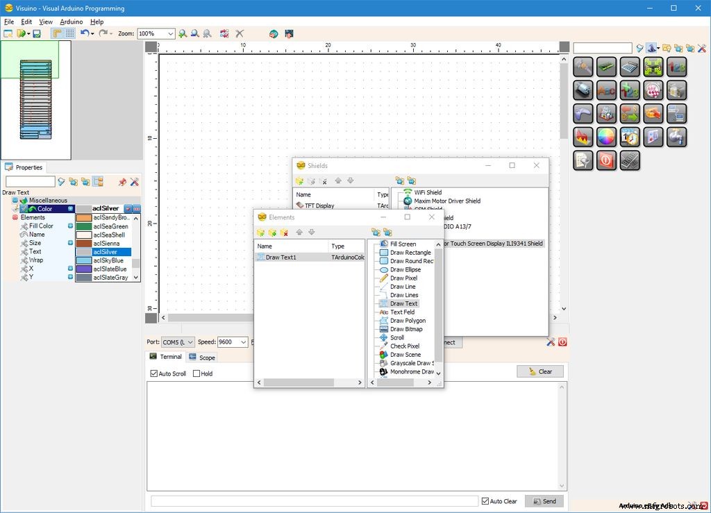 <図>
<図> 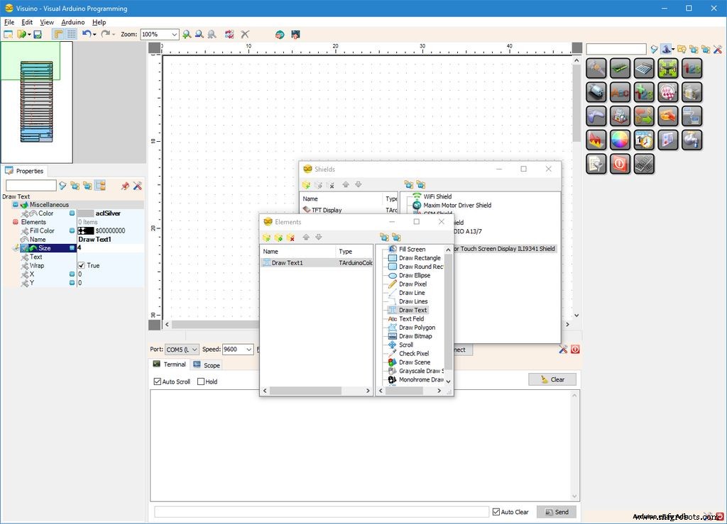 <図> <図>
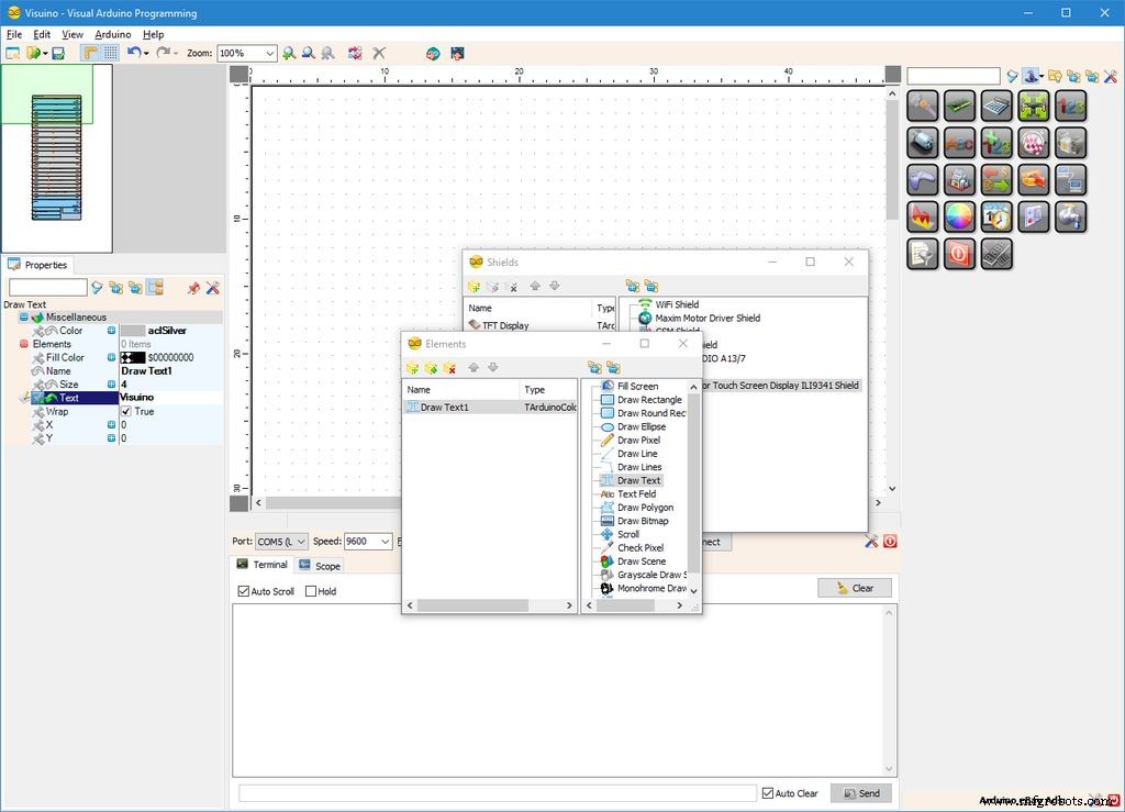
次に、テキストとビットマップをレンダリングするためのグラフィック要素を追加する必要があります。まず、テキストの影を描くためのグラフィック要素を追加します:
- オブジェクトインスペクターで、[ ... ]をクリックします 「要素」の値の横にある「」ボタン 「 TFTディスプレイの」プロパティ "要素(写真1 )
- 要素エディタで「テキストの描画」を選択します 」をクリックし、[ + ]をクリックします "ボタン(写真2 )1つ追加します(写真3 )
- オブジェクトインスペクターで、「色」の値を設定します " Draw Text1 の"プロパティ "要素から" aclSilver "(写真3 )
- オブジェクトインスペクターで、「サイズ」の値を設定します " Draw Text1 の"プロパティ "要素から" 4 "(写真4 )。これにより、テキストが大きくなります
- オブジェクトインスペクターで、「テキスト」の値を設定します " Draw Text1 の"プロパティ "要素から" Visuino "(写真5 )
- オブジェクトインスペクターで「 X 」の値を設定します " Draw Text1 の"プロパティ "要素から" 43 "(写真6 )
- オブジェクトインスペクターで「 Y 」の値を設定します " Draw Text1 の"プロパティ "要素から" 278 "(写真6 )
ステップ5:Visuinoの場合:テキストの前景に描画テキスト要素を追加します <図>
 <図>
<図>  <図>
<図> 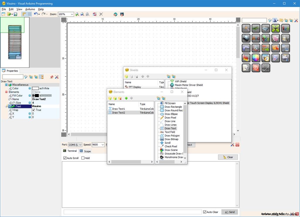 <図>
<図> 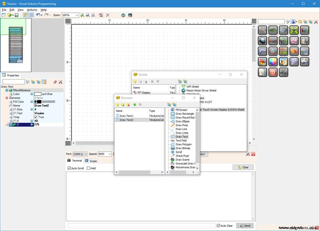
次に、テキストを描画するためのグラフィック要素を追加します:
- 要素エディタで「テキストの描画」を選択します 」をクリックし、["]ボタンをクリックします(写真1 )2番目のものを追加します(写真2 )
- オブジェクトインスペクターで、「サイズ」の値を設定します " Draw Text1 の"プロパティ "要素から" 4 "(写真2 )
- オブジェクトインスペクターで、「テキスト」の値を設定します " Draw Text1 の"プロパティ "要素から" Visuino "(写真3 )
- オブジェクトインスペクターで「 X 」の値を設定します " Draw Text1 の"プロパティ "要素から" 40 "(写真4 )
- オブジェクトインスペクターで「 Y 」の値を設定します " Draw Text1 の"プロパティ "要素から" 275 "(写真4 )
ステップ6:Visuinoの場合:アニメーションの描画ビットマップ要素を追加します <図>
 <図>
<図> 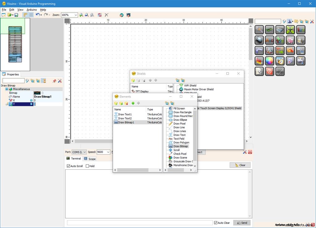 <図>
<図> 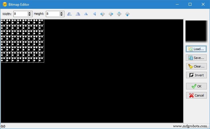 <図>
<図> 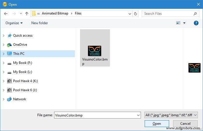 <図>
<図> 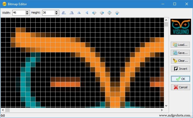
次に、ビットマップを描画するためのグラフィック要素を追加します:
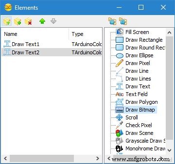
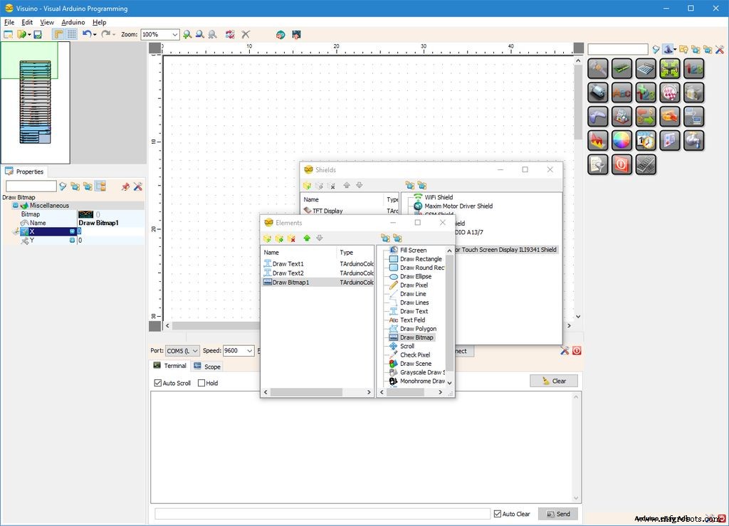
- 要素エディタで「ビットマップの描画」を選択します 」をクリックし、["]ボタンをクリックします(写真1 )1つ追加します(写真2 )
- オブジェクトインスペクターで、[ ... ]をクリックします 「ビットマップ」の値の横にある「」ボタン " Draw Bitmap1 の"プロパティ "要素(写真2 )「ビットマップエディタ」を開きます "(写真3 )
- 「ビットマップエディタ」 "[読み込み... ]をクリックします "ボタン(写真3 )[ファイルを開く]ダイアログを開きます(画像4 )
- [ファイルを開く]ダイアログで、描画するビットマップを選択し、[開く]をクリックします。 "ボタン(写真4 )。ファイルが大きすぎると、Arduinoメモリに収まらない可能性があります。コンパイル中にメモリ不足エラーが発生した場合は、小さいビットマップを選択する必要がある場合があります
- 「ビットマップエディタ」 「 OK をクリックします 。」ボタン(写真5 )ダイアログを閉じる
ステップ7:Visuinoの場合:描画ビットマップ要素のXプロパティとYプロパティのピンを追加します <図>
 <図>
<図> 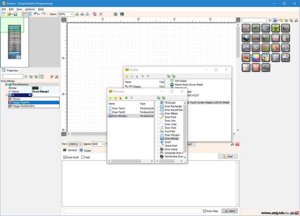 <図> <図>
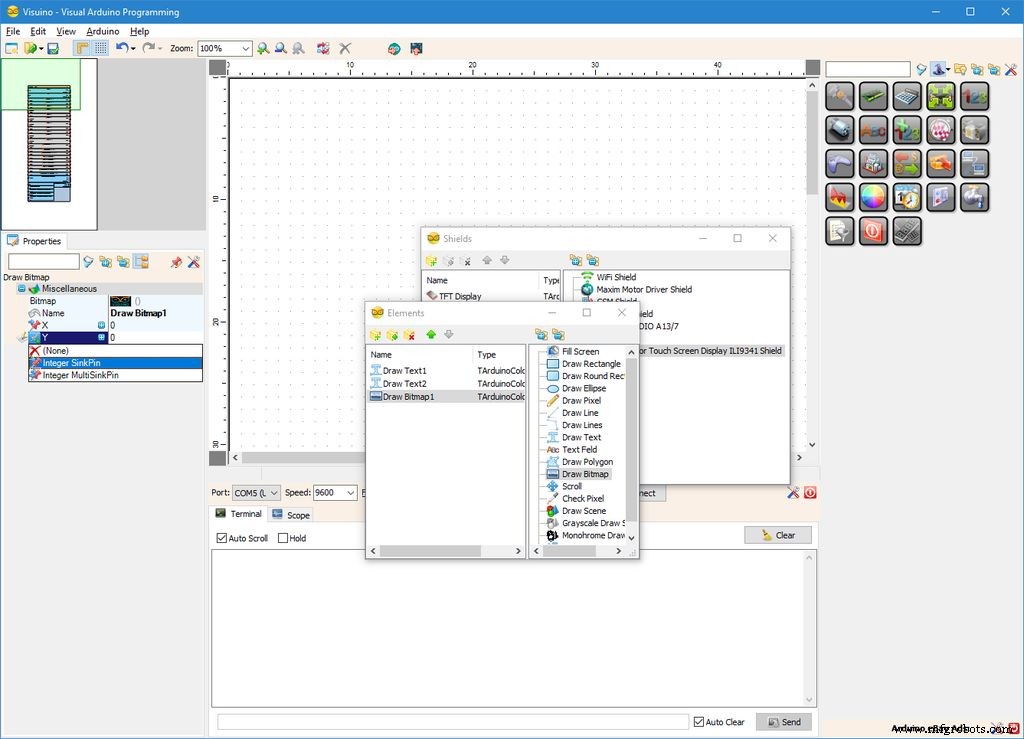
ビットマップをアニメーション化するには、XとYの位置を制御する必要があります。このために、XプロパティとYプロパティのピンを追加します。
- オブジェクトインスペクターで[ピン]をクリックします 「 X 」の前にある「」ボタン " Draw Bitmap1 の"プロパティ "要素(写真1 )、[ Integer SinkPin ]を選択します "(写真2 )
- オブジェクトインスペクターで[ピン]をクリックします 「 Y 」の前にある「」ボタン " Draw Bitmap1 の"プロパティ "要素(写真3 )、[ Integer SinkPin ]を選択します "(写真4 )
ステップ8:Visuinoの場合:2つの整数正弦波ジェネレーターを追加し、最初のジェネレーターを構成します <図>
 <図>
<図> 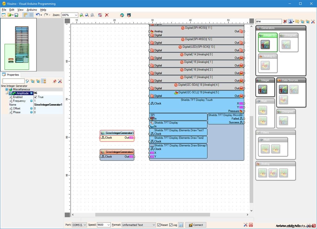 <図>
<図> 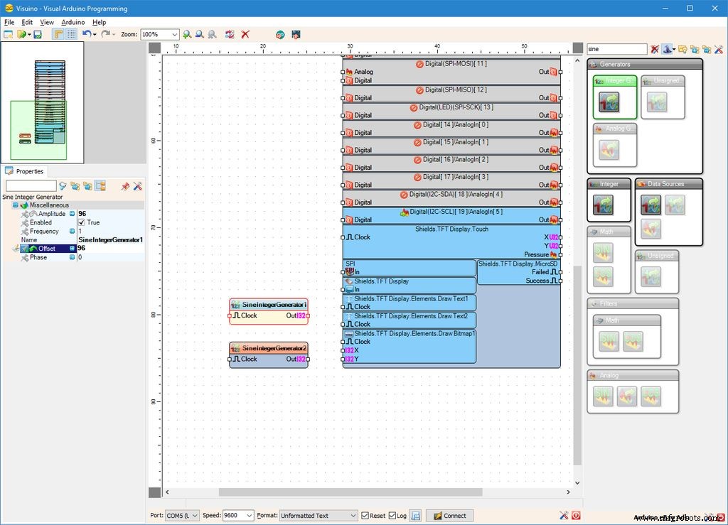 <図>
<図> 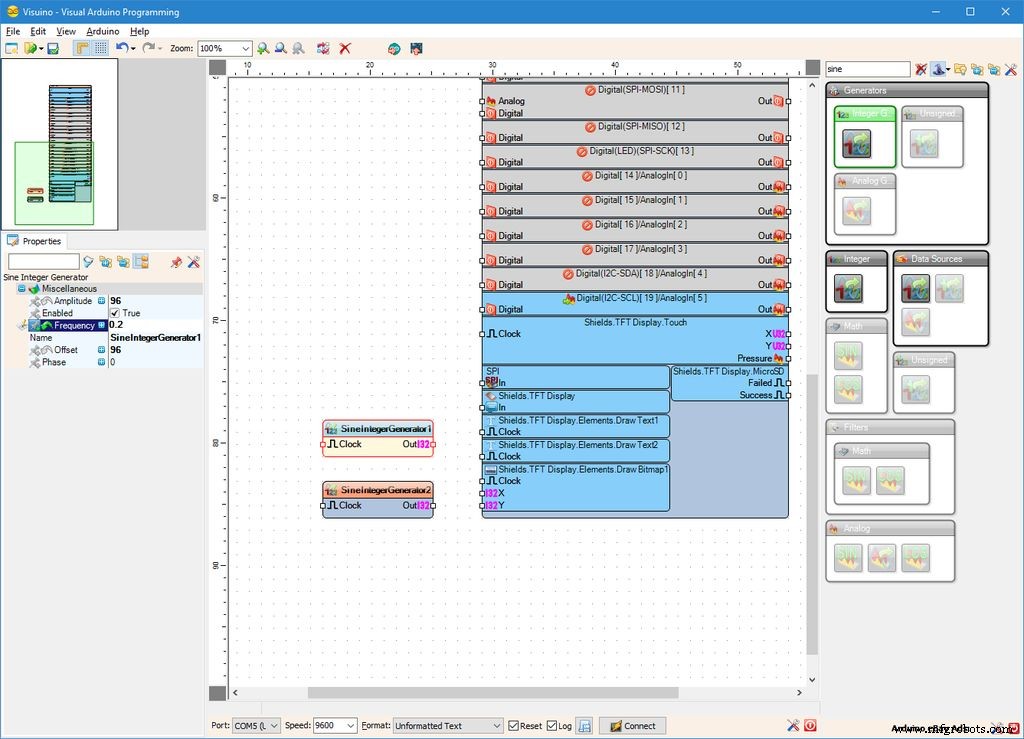
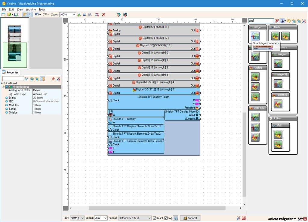
ビットマップの動きをアニメーション化するために、2つの整数正弦波ジェネレーターを使用します。
- 「正弦」と入力します [コンポーネントツールボックス]の[フィルター]ボックスで、[正弦整数ジェネレーター]を選択します。 "コンポーネント(写真1 )、 2つをドロップします デザインエリアにあります
- オブジェクトインスペクターで、「振幅」の値を設定します " SineIntegerGenerator1 のプロパティ 「 96 」のコンポーネント "(写真2 )
- オブジェクトインスペクターで、「オフセット」の値を設定します " SineIntegerGenerator1 のプロパティ 「 96 」のコンポーネント "(写真3 )
- オブジェクトインスペクターで、「頻度」の値を設定します " SineIntegerGenerator1 のプロパティ 「 0.2 」へのコンポーネント "(写真4 )
ステップ9:Visuinoの場合:2番目の正弦波ジェネレーターを構成し、正弦波ジェネレーターをビットマップのX座標ピンとY座標ピンに接続します <図>
 <図>
<図> 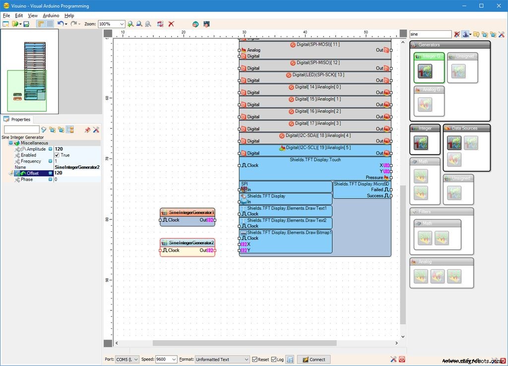 <図>
<図> 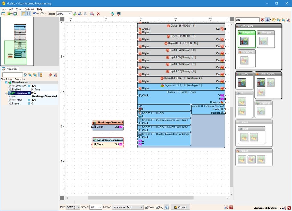 <図>
<図>  <図>
<図> 
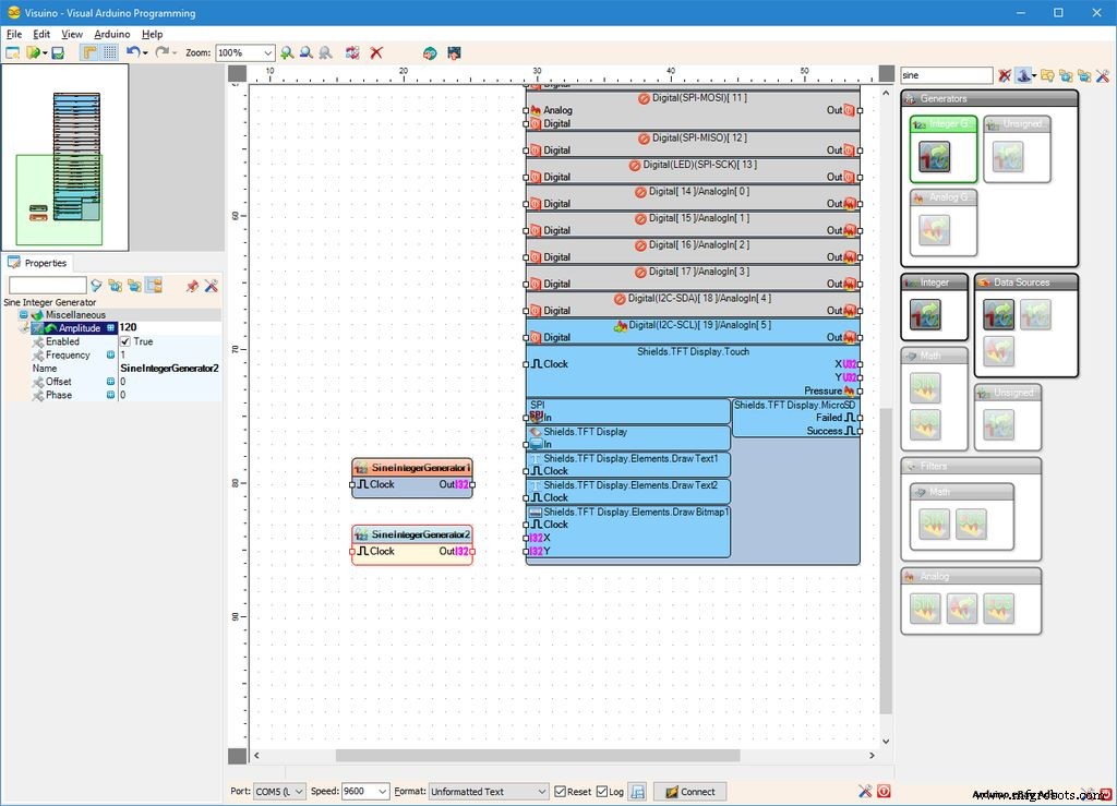
- オブジェクトインスペクターで、「振幅」の値を設定します " SineIntegerGenerator2 のプロパティ 「 120 」のコンポーネント "(写真1 )
- オブジェクトインスペクターで、「オフセット」の値を設定します " SineIntegerGenerator2 のプロパティ 「 120 」のコンポーネント "(写真2 )
- オブジェクトインスペクターで、「頻度」の値を設定します " SineIntegerGenerator2 のプロパティ コンポーネントを「 0.03 "(写真3 )
- 「アウト」を接続します " SineIntegerGenerator1 の出力ピン 「 X 」のコンポーネント 「 Shields.TFTSisplay.Elements.Draw Bitmap1 の入力ピン " Arduino の要素 コンポーネント(写真4 )
- 「アウト」を接続します " SineIntegerGenerator2 の出力ピン 「 Y 」のコンポーネント " Shields.TFT Display.Elements.Draw Bitmap1 の入力ピン " Arduino の要素 コンポーネント(写真5 )
ステップ10:Visuinoの場合:StartおよびClockマルチソースコンポーネントを追加して接続します <図>
 <図>
<図> 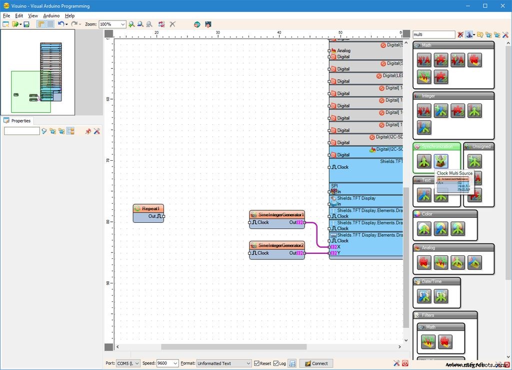 <図>
<図> 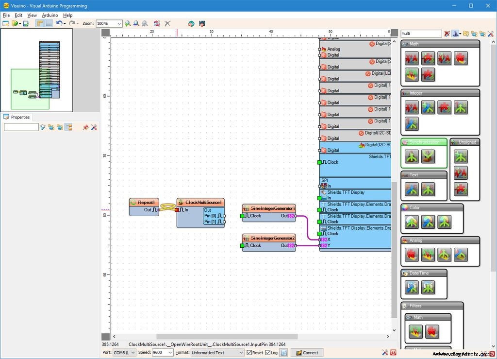 <図>
<図>  <図>
<図> 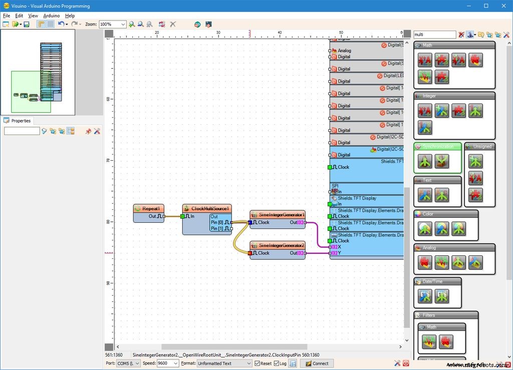 <図>
<図> 
XとYの位置が更新されるたびにビットマップをレンダリングするには、「DrawBitmap1」要素にクロック信号を送信する必要があります。位置が変更された後にコマンドを送信するには、イベントを同期する方法が必要です。このために、Repeatコンポーネントを使用して常にイベントを生成し、Clock MultiSourceを使用して2つのイベントを順番に生成します。最初のイベントは正弦波ジェネレーターをクロックしてXとYの位置を更新し、2番目のイベントは「DrawBitmap1」をクロックします:
- 「繰り返し」と入力します [コンポーネントツールボックス]の[フィルター]ボックスで、[繰り返し]を選択します。 "コンポーネント(写真1 )、デザインエリアにドロップします(写真2 )
- 「マルチ」と入力します [コンポーネントツールボックス]の[フィルター]ボックスで、[クロックマルチソース]を選択します。 "コンポーネント(写真2 )、デザインエリアにドロップします(写真3 )
- 「アウト」を接続します " Repeat1 の出力ピン 「 In 」のコンポーネント " ClockMultiSource1 の入力ピン コンポーネント(写真3 )
- 「ピン[0] 」を接続します 「出力」の出力ピン " ClockMultiSource1 のピン 「 In 」のコンポーネント " SineIntegerGenerator1 の入力ピン コンポーネント(写真4 )
- 「ピン[0] 」を接続します 「出力」の出力ピン " ClockMultiSource2 のピン 「 In 」のコンポーネント " SineIntegerGenerator1 の入力ピン コンポーネント(写真5 )
- 「ピン[1] 」を接続します 「時計の」出力ピン " Shields.TFT Display.Elements.Draw Bitmap1 の入力ピン " Arduino の要素 コンポーネント(写真6 )
ステップ11:Arduinoコードを生成、コンパイル、アップロードする <図>
 <図>
<図> 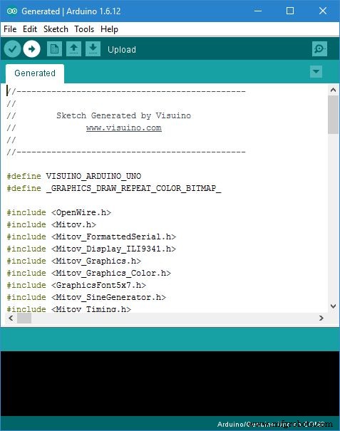
- Visuino 、 F9 を押します または、写真1 に表示されているボタンをクリックします Arduinoコードを生成し、ArduinoIDEを開きます
- Arduino IDE 、アップロードをクリックします ボタンをクリックして、コードをコンパイルしてアップロードします(写真2 )
ステップ12:そしてプレイ... <図>
 <図>
<図> 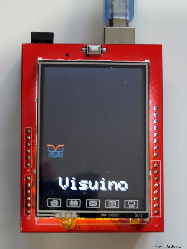 <図>
<図> 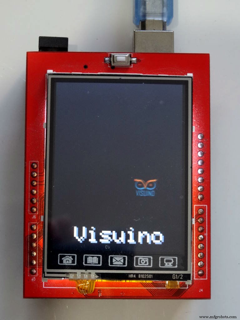 <図>
<図> 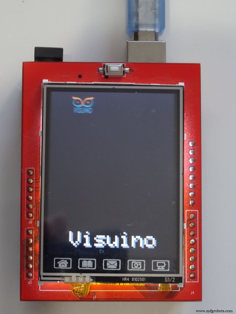 <図>
<図> 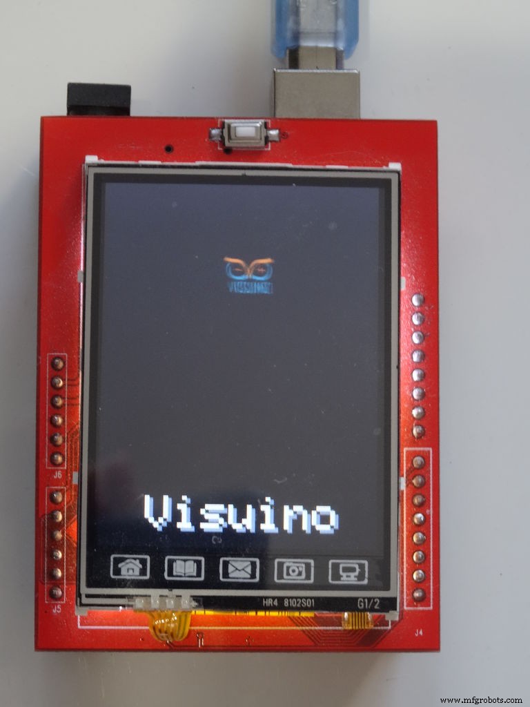
おめでとうございます! プロジェクトが完了しました。
写真2、3、4、5 とビデオ 接続され、電源が入っているプロジェクトを表示します。ビットマップが ILI9341ベースのTFTタッチスクリーンディスプレイシールドの周りを移動しているのがわかります。 ビデオで見られるように 。
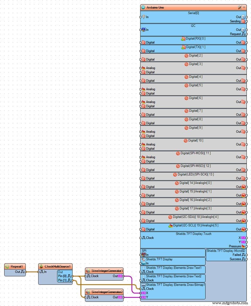
写真1 完全な Visuino を見ることができます 図。 Visuino も添付されています このチュートリアル用に作成したプロジェクトと、 Visuino を使用したビットマップ ロゴ。ダウンロードして Visuino で開くことができます :https://www.visuino.com
FPHWHL0IV0AHJLX.zip
製造プロセス