


Coin Op Personal Vending Machine
コンポーネントと消耗品
| × | 4 | ||||
| × | 1 | ||||
| × | 1 | ||||
| × | 1 | ||||
| × | 1 | ||||
| × | 1 | ||||
 |
| × | 1 | |||
| × | 1 | ||||
 |
| × | 1 | |||
| × | 1 | ||||
| × | 1 | ||||
| × | 2 | ||||
| × | 1 | ||||
| × | 1 |
必要なツールとマシン
| ||||
 |
| |||
 |
|
アプリとオンラインサービス
>  |
|
このプロジェクトについて
個人用自動販売機
このプロジェクトは、個人用自動販売機の段階的な構築です。自動販売機には、お気に入りのスナックを入れたり、オフィスに持って行ったりして、チームとおやつを共有することができます。見て、あなたの考えを教えてください。
マシンの構築:
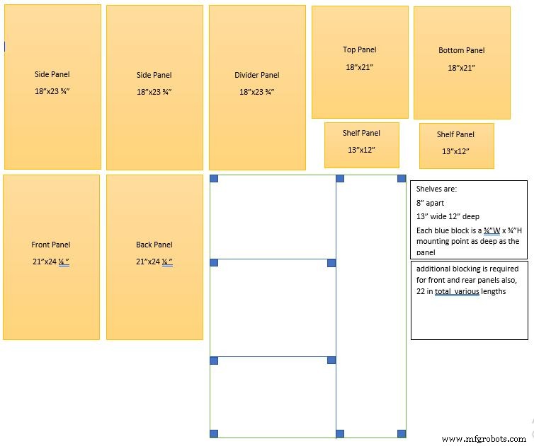
このテキスト全体で機械の図を参照しますので、説明/理解のために図を参照してください。
機械の寸法は21 "W x 18" D x 24 1/4 "H(ボックス寸法)
2つのパネル18 "D x 23 3/4" H(側面)
2つのパネル21 "W x 18" D(上下)
2つのパネル21 "W x 24 1/4" H(前面と背面)
仕切り壁は18 "D x 23 3/4" H
内部シェルフは13 "W x 12" D(2倍、上下のシェルフ)
棚板は8インチ離れており、幅は13インチ、奥行きは12インチです
パネル図の青いブロックはそれぞれ、パネルと同じ深さの3/4” W x¾” Hの取り付けポイントです
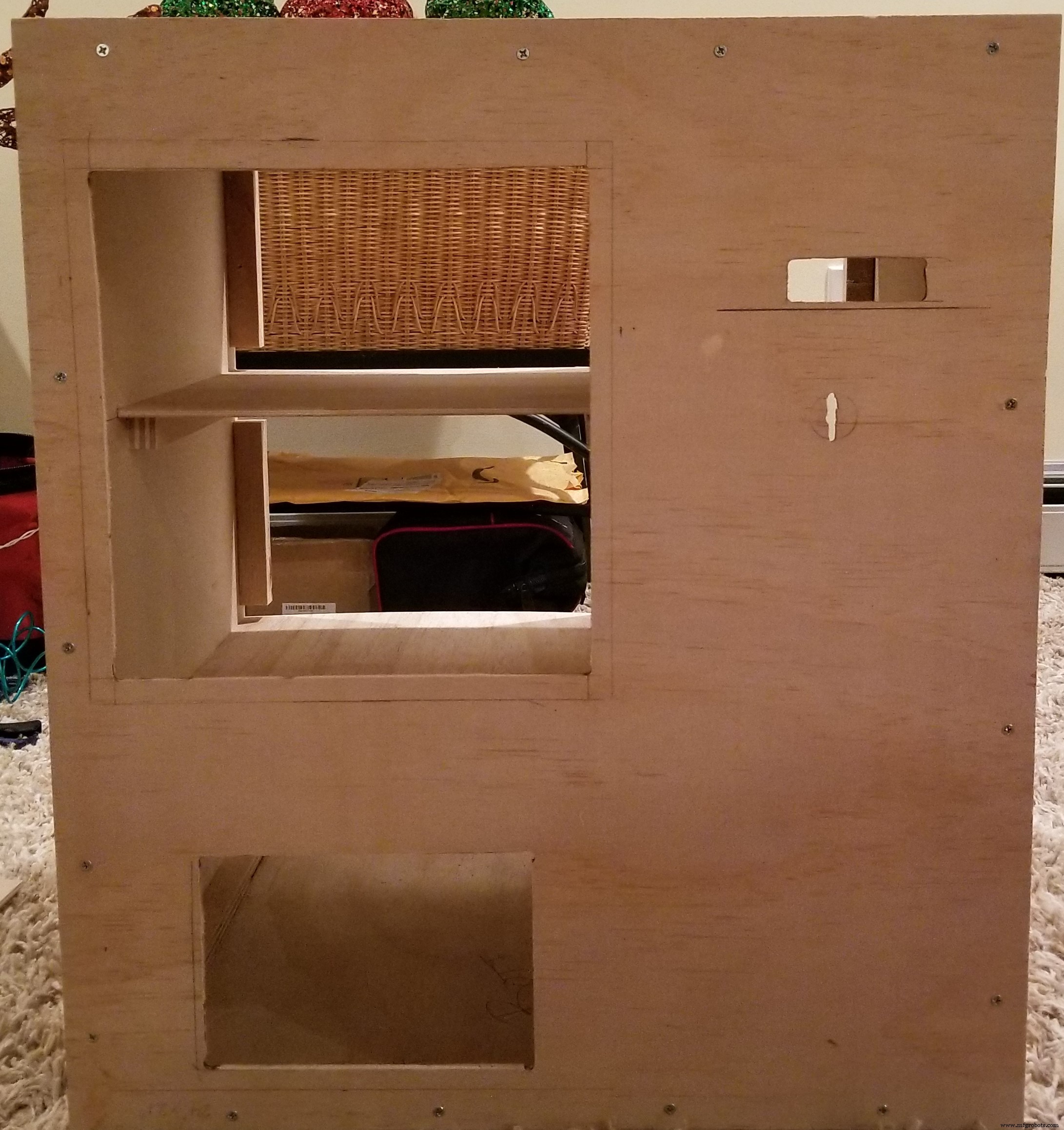
図に示すように、ここでは各接合点で3/4 "ブロッキングを使用して、ボックスを組み立てます。側壁が底板の上と天板の下にあることに注意してください。周囲の壁の長さは21" Wである必要があります。 24 1/4 "H。
設置する前に、仕切り壁を設定する必要があります。上部から161/4 "を測定し、下部の棚にブロッキングを取り付けます。上部から8 1/4"を測定し、上部の棚にブロッキングを取り付けます。左側の壁(機械の正面から見て)でこれらの手順を実行して、上部と下部の棚にブロッキングを取り付けることができるようにします。
****一番下の棚を最初に取り付ける必要があることに注意してください。そうしないと、ブロッキングへの固定が非常に困難になります。
棚板にブロッキングを取り付けたら、13 "x 12"のパネルを使用して、ブロッキングの各セットに1つずつ取り付けます。これにより、仕切り壁が適切な場所に自動的に設定されます。次に、仕切り壁の右側の上部と下部でブロッキングを固定します。次に、それを上部パネルと下部パネルに固定します。これにより、構造が完全に確実になります。
背面パネルを取り付けて、モーターの取り付けの準備をします。コイルホイールを測定してドリル穴を設定できるように、コイルホイールが印刷されていることを確認してください。ホイールを測定し、コイルが回転する余地が残るように高さに1/4 "を追加します。材料に応じて、必要に応じて調整することをお勧めします。棚の6 1/2"を測定して、そのマークを付けます。真ん中。 3 1/4 "を超えて測定し、各棚セクションの中心を見つけます。少し前に記録した高さ測定値を使用して、ドリルポイントを見つけます。ホイールシャフトをこすらずにホイールをモーターに接続できる穴を開けます。ボード。モーターの取り付けと留め具のねじ込みを完了します。
モーターリレーの設定:
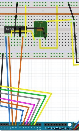
次のようにピンを接続します。リレーを制御できるように、チップL293D(左側のノッチ)(回路図)を使用します。これにより、モーターを電源に接続できるようになります。
(左から右に開始)
ピン1はコントローラーのピンソケット10に接続します(回路図内)
ピン2はコントローラーのピンソケット9に接続します(回路図内)
ピン3はリレーのプラス側に接続します(3つのピンを手前に、ピンを左側に)(回路図)
ピン4はブレッドボードの12Vアースに接続します(回路図内)
ピン5未使用(回路図)
ピン6はリレーのアース側に接続します(3つのピンを手前に、ピンを右に向けます)(回路図)
ピン7はコントローラーのピンソケット8に接続します(回路図内)
ピン8はブレッドボードの+ 12Vに接続します(回路図内)
リレーの中央のピンをブレッドボードの+ 12Vに接続します(回路図内)
リレーの右後ろのピン(3つのピンを手前に向け、ピンを右に後ろに向ける)を、モータードライバーにつながるプラスのリード線に接続します(回路図内)
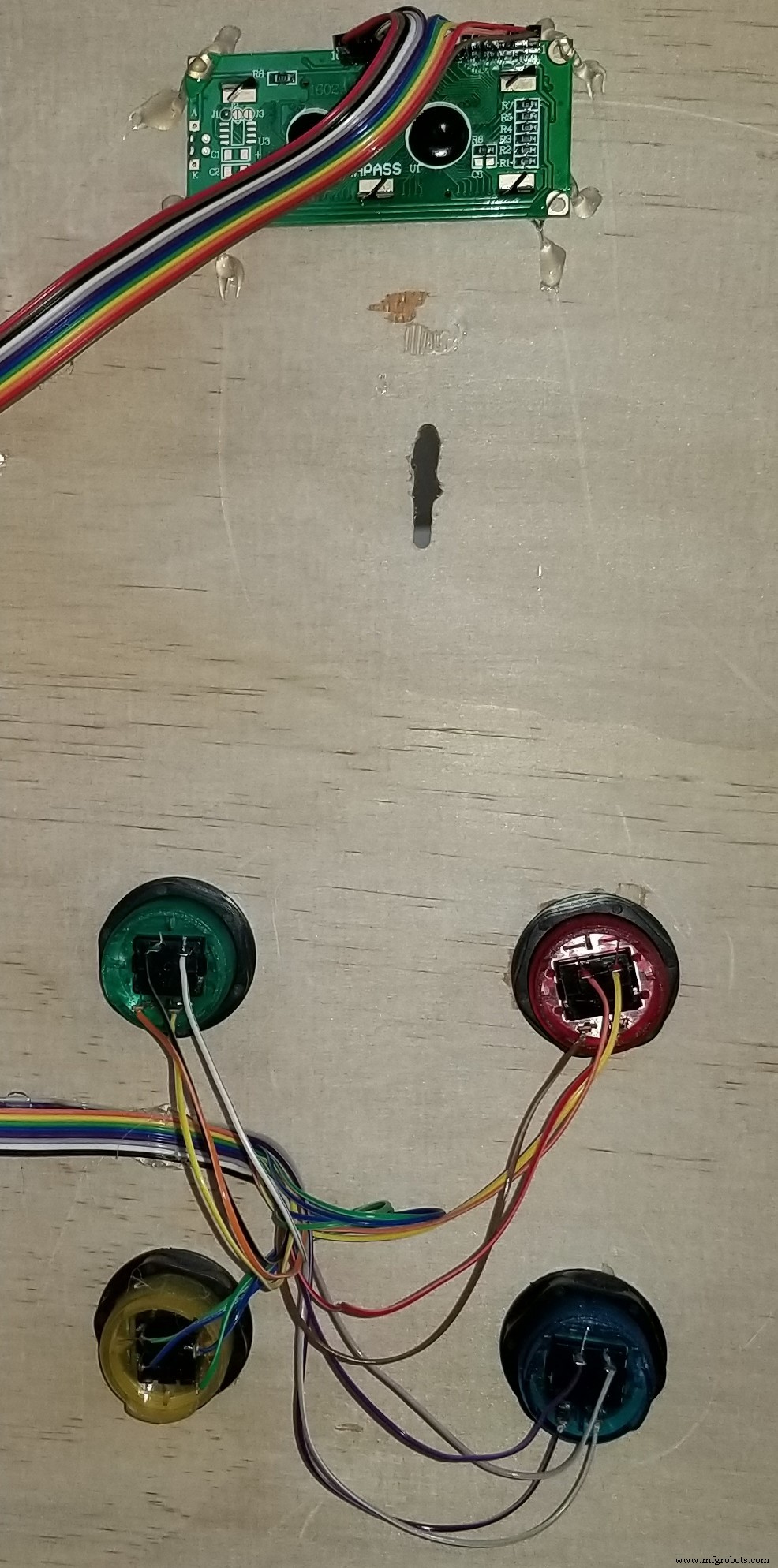
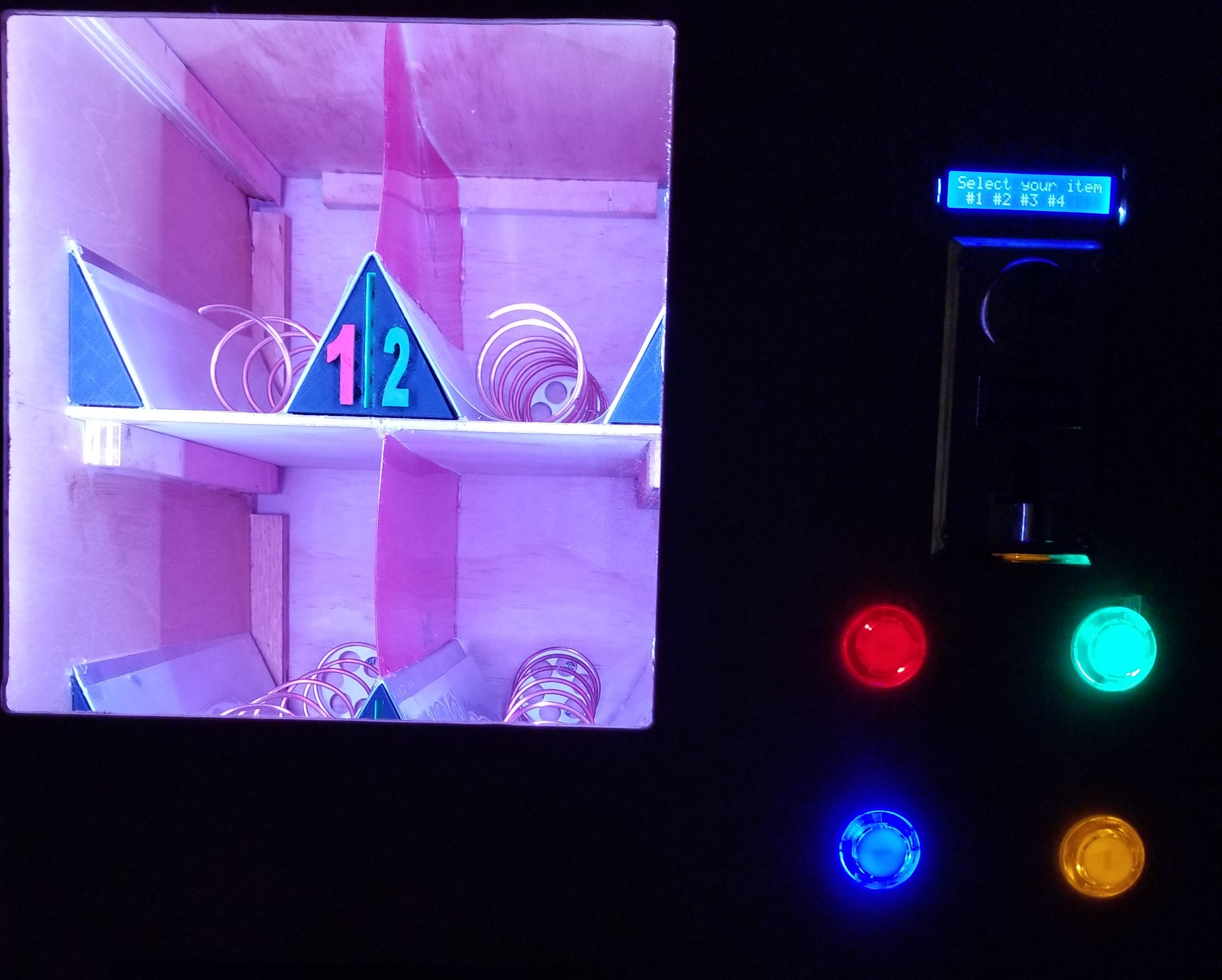
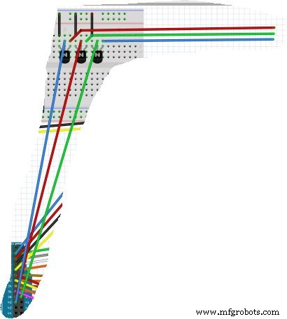
画面とボタンの取り付け:画面-マシンの右側(マシンを正面から見た場合)の場所を選択し、画面の表示部分(2.53937 "x 0.5708661)ボタン用に作成する必要のある穴に印を付けます。 -マシンの右側(マシンを正面から見て)の場所を選び、4つのボタンに必要な穴をマークします。まったく同じボタンを使用する場合は、穴を1.10236 "にする必要があります。パーツリスト。必要なサイズよりも少し小さいドリルとサンドペーパーを使用して、必要なサイズに仕上げるのが好きです。
上の図とまったく同じ場所にすべての接続があることを確認する必要があることに注意してください。図に示されているLEDは、押しボタンに組み込まれているLEDです。ダイアグラムはそれらを別々に示していますが、これは表示用であり、回路図を読みやすくするためのものです。
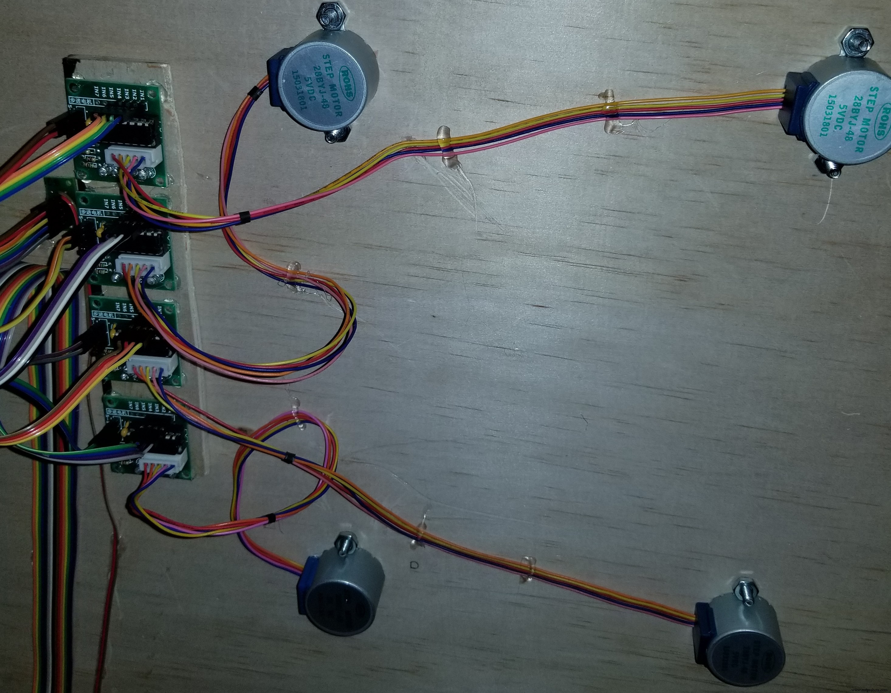
各モーターを付属のドライバーに接続します。次に、次の手順を使用して各ドライバーをコントローラーに接続します。
モーターの設定:
ブレッドボードの12V側に電源を接続する必要があります。この電源は、最後に準備するATX電源から供給されます。次に、ドライバの4つの「入力」ピンをコントローラに接続します。これらのピンは次のとおりです
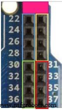
*********このブロックの最初の2つのピンには接続しないでください。これらは5Vピンです-このプロジェクトでは使用されません*********
モーター1:青いピン22、24、26、28(回路図内)
モーター2:黄色のピン23、25、27、29(回路図内)
モーター3:緑色のピン30、32、34、36(回路図内)
モーター4:赤いピン31、33、35、37(回路図内)
ボタン接続:
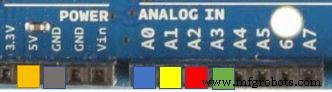
押しボタン1の一方の側を5vに電力を供給し、もう一方の側をアナログピンA0(回路図内)とともに接地された220抵抗に接続します
押しボタン2の一方の側を5vに電力を供給し、もう一方の側をアナログピンA1(回路図内)とともに接地された220抵抗に接続します
押しボタン3の一方の側を5vに電力を供給し、もう一方の側をアナログピンA2(回路図内)とともに接地された220抵抗に接続します
押しボタン4の一方の側を5vに電力を供給し、もう一方の側をアナログピンA3(回路図内)とともに接地された220抵抗に接続します
LCD画面:
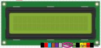
画面をブレッドボードの5v側に接続して、電源とアースを確保します
ピンは次のとおりです:
ピン1:アースに接続(回路図内)
ピン2:5v電源に接続します(回路図内)
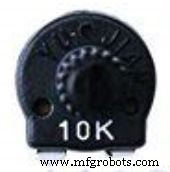
ピン3:調整可能なポテンショメータに接続します(下の写真)左下のピンをアースに、右下を電源に、上のピンをLCDのピン3に接続します(回路図では、これはLCDのコントラストを設定して、テキストが鮮明になるようにする方法です。きれい)
ピン4:コントローラーピンソケット2への最初の信号ピン(回路図内)
ピン5:アースに接続(回路図内)
ピン6:コントローラーピンソケット3への2番目の信号ピン(回路図内)
ピン7:未使用
ピン8:未使用
ピン9:未使用
ピン10:未使用
ピン11:コントローラーピンソケット4への3番目の信号ピン(回路図内)
ピン12:コントローラーピンソケット5への4番目の信号ピン(回路図内)
ピン13:コントローラーピンソケット6への5番目の信号ピン(回路図内)
ピン14:コントローラーピンソケット7への6番目の信号ピン(回路図内)
ピン15:5v電源に接続します(回路図内)
ピン16:アースに接続(回路図内)
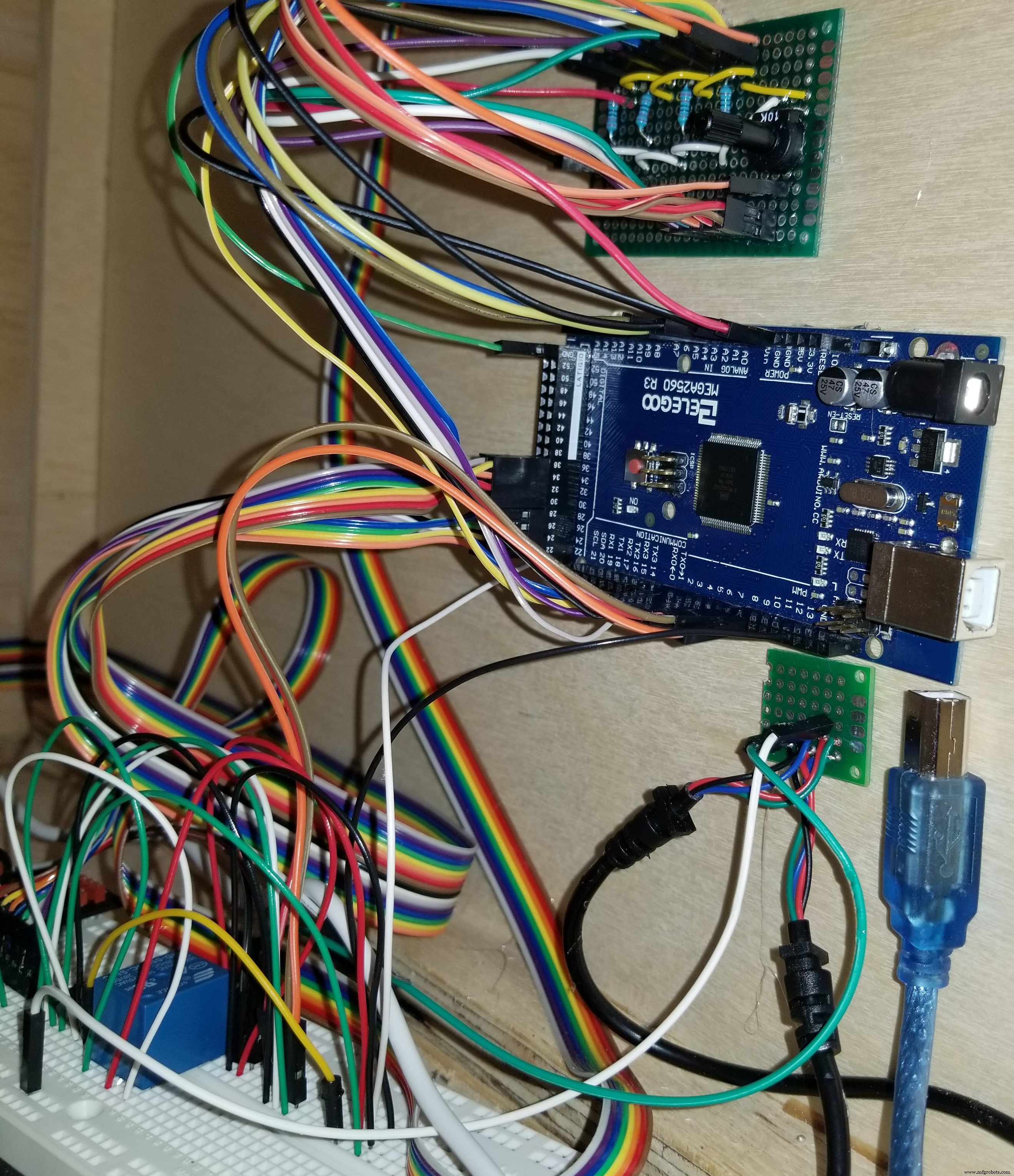
ATX電源 :
デバイスに電力を供給するために必要なワイヤーのみを切断してください。他のワイヤはプラスチックコネクタの方が安全であり、必要に応じて他のプロジェクトに使用できます。
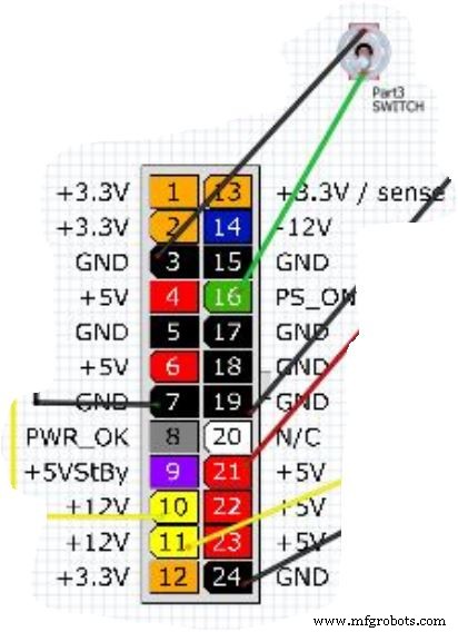
ATXピン:
(アース)黒線ピン3と(信号)緑線ピン16をカットアンドストリップします。これらのワイヤーをスイッチに接続して、マシンの電源をオン/オフできるようにします(回路図内)
(アース)黒のワイヤーピン7と(+ 12V)黄色のワイヤーピン10をカットアンドストリップします。これらのワイヤーを、黄色と黒の接続で指定されたブレッドボードの12v側に接続します。 (回路図内)
黒いワイヤーピン24と(+ 12V)黄色のワイヤーピン11をカットアンドストリップします。これらのワイヤーを互換性のあるコネクターに接続して、Arduinoボードに電力を供給します(回路図内)
(アース)黒いワイヤーピン19と(+ 5V)赤いワイヤーピン21をカットアンドストリップします。これらのワイヤーをブレッドボードの5V側に取り付けます(回路図内)
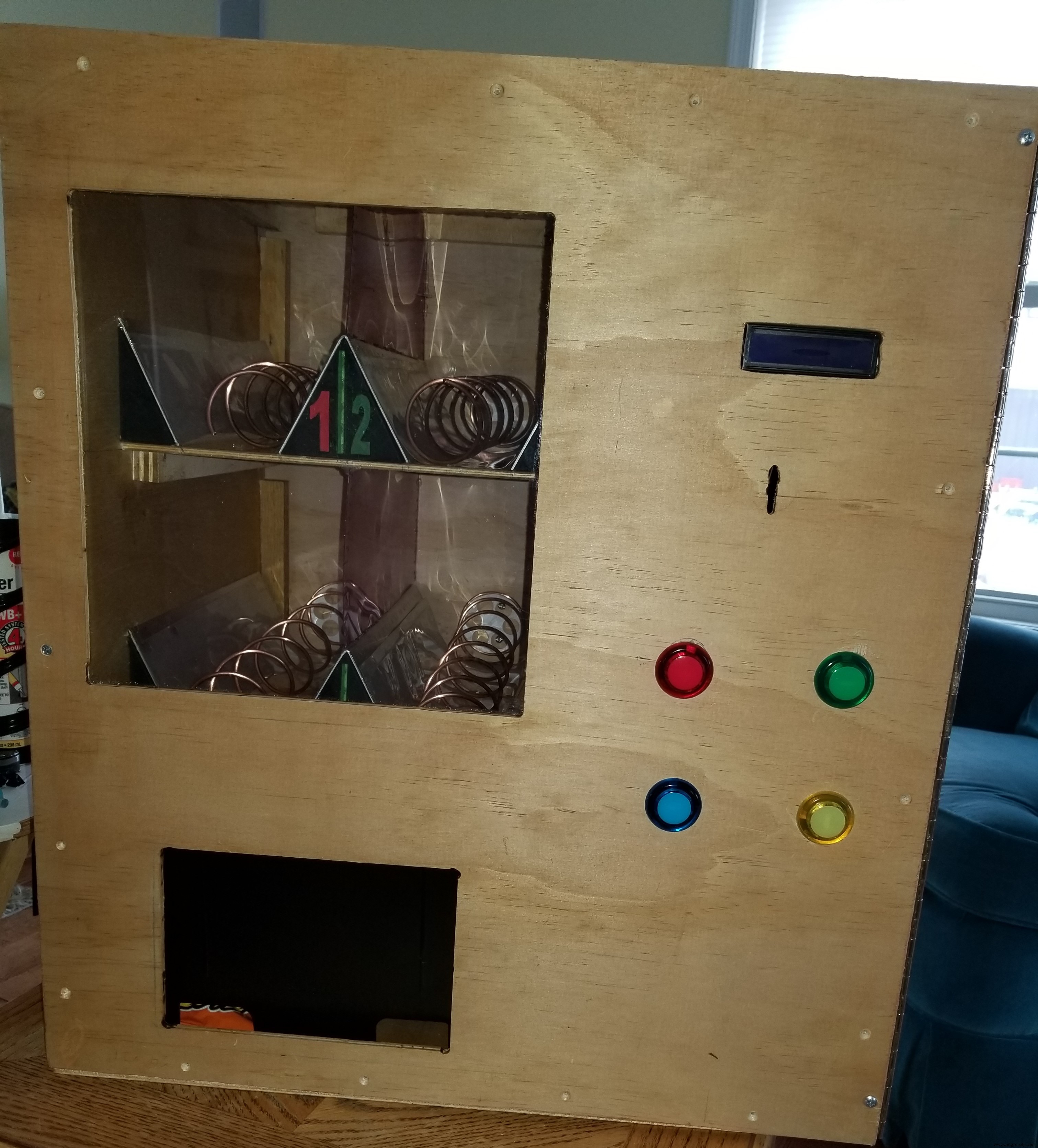
棚の仕切りとコイル:
棚と押出機のセットアップ方法は次のとおりです。
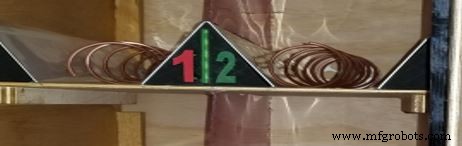
棚-左側の側壁(機械を正面から見た場合)または仕切り壁から6 1/2 "の中間点に、上記の手順のマークがあるはずです。平らな金属を使用して、上部に曲げます。三角形。この「^」のように見えます。これは中央の仕切りとして機能します。三角形を棚の中央のマークの中央に配置します。2番目の棚についても繰り返します。ホットグルーを使用して固定します。スライドも側面に配置しますが、オプションです。
コイル-コイルを作成するには、最初に1 1/2 "チューブを見つけます。パイプ、コーキングチューブ、スプレーペイント缶、または同様のオブジェクトで十分です。1つのトリックは、輪ゴムを取り、長さ全体に上から下に巻き付けることです。チューブの両側のバンドの両側に直線をトレースします。両側に平行線ができたら、テープメジャーを使用して次のスポットをマークします。片側を選び、1 "で測定してマークします。 、次にそこから2 "を測定し、それをマークして、チューブのずっと下まで2"のスペースを作り続けます。ここで、チューブの反対側に2 "間隔だけマークを付けます。チューブの1"側でコイルの作成を開始し、チューブの両側の各マークに接触するようにコイルの作成を続けます。これにより、ラング間に2 "のギャップができます。ほとんどのアイテムに十分な大きさである必要があります。キャンディーバードに使用する場合は、コイルを1"に短くして、上記の式を半分に減らしてください。
コイルを3Dプリントされたホイールに接続します。動作するいくつかの製造されたホイールがあることに注意してください。アマゾンを見てください。
コイルの1 "側で、このコイルを折りたたんで円を作ります。次に、直径をホイールよりわずかに小さくします。コイルの準備ができたら、コイルをホイールの端に合わせます。これにより、コイルが圧縮されます。ホイールの端を滑らせないようにします。フィット感に満足したら、ホットグルーを少し塗り、コイルの端にあるホイールに置いて、所定の位置に保持します。
LEDストリップライト:
ブレッドボードの12V側の+ 12Vピンにプラスのリード線を接続します。パンボードの12V側のアースピンにアース線を接続します(図にはありません)
あなたが持っているすべての質問をしてください。私はこれをこれまでで最も簡単なプロジェクトにするために更新を支援することができます。
コード
- 自動販売機-LEDライトを変更せずに
- 自動販売機-LEDライトを変更する
- コインアクセプターと完全なコピー
自動販売機-LEDライトを変更せずに Arduino
プロジェクトを完了して理解するために必要なすべて// Display#includeLiquidCrystal lcd(2、3、4、5、6、7); // Stepper Library#include / /ステッピングモーターライブラリを含む// RelaySetup#define ENABLE 10#define DIRA 8#define DIRB 9 // Define "i" int i; // definingピンセクション// StepperConnect 1int stepIN1Pin =22; int stepIN2Pin =24; int stepIN3Pin =26; int stepIN4Pin =28; // Stepper Connect 2int stepIN1Pin1 =23; int stepIN2Pin1 =25; int stepIN3Pin1 =27; int stepIN4Pin1 =29; // Stepper Connect 3int stepIN1Pin2 =30; int stepIN2Pin2 =32; int stepIN3Pin2 =34; int stepIN4Pin2 =36; // Stepper Connect 4int stepIN1Pin3 =31; int stepIN2 =33; int stepIN3Pin3 =35; int stepIN4Pin3 =37; // stepsintstepsPerRevolutionを定義=2048; // 1回転あたりのステップ数//ボタンのピンポートを定義constint button1Pin =A0; //プッシュボタン1アナログピンA0constint button2Pin =A1; //プッシュボタン2アナログピンA1constint button3Pin =A2; //プッシュボタン3アナログピンA2constint button4Pin =A3; //プッシュボタン4アナログピンA3 //各ステッパーを定義// 1Stepper myStepper0(stepsPerRevolution、stepIN1Pin、stepIN3Pin、stepIN2Pin、stepIN4Pin); // 2Stepper myStepper1(stepsPerRevolution、stepIN1Pin1、stepIN3Pin1、stepIN2Pin1、stepIN4Pin1); // 3 StepsPerRevolution、stepIN1Pin2、stepIN3Pin2、stepIN2Pin2、stepIN4Pin2); // 4Stepper myStepper3(stepsPerRevolution、stepIN1Pin3、stepIN3Pin3、stepIN2Pin3、stepIN4Pin3); void setup(){//プッシュボタンピン入力の割り当て:pinMode(button1Pin、INPUT); pinMode(button2Pin、INPUT); pinMode(button3Pin、INPUT); pinMode(button4Pin、INPUT); //ピン出力を割り当てますpinMode(ENABLE、OUTPUT); pinMode(DIRA、OUTPUT); pinMode(DIRB、OUTPUT); //ステッパー速度を割り当てますmyStepper0.setSpeed(15); myStepper1.setSpeed(15); myStepper2.setSpeed(15); myStepper3.setSpeed(15); // LCDディスプレイを初期化しますlcd.begin(16、2); lcd.clear(); lcd.setCursor(0、0); lcd.print( "アイテムを選択"); lcd.setCursor(0、1); lcd.print( "#1#2#3#4");} void loop(){//ボタンの割り当てを読み取るint button1State、button2State、button3State、button4State; button1State =digitalRead(button1Pin); button2State =digitalRead(button2Pin); button3State =digitalRead(button3Pin); button4State =digitalRead(button4Pin); digitalWrite(ENABLE、HIGH); //(i =0; i <5; i ++);の状態を設定します。 //ボタン1が押されたときのアクションを定義if(((button1State ==LOW)&&!(button2State ==LOW)))//ボタン1またはボタン2を押している場合{digitalWrite(DIRA、HIGH); //リレーを使用しますdigitalWrite(DIRB、LOW); lcd.clear(); lcd.setCursor(2、0); lcd.print( "ディスペンシング"); lcd.setCursor(3、1); lcd.print( "あなたのアイテム"); myStepper0.step(stepsPerRevolution); //モーターを実行しますlcd.clear(); lcd.setCursor(2、0); lcd.print( "取ってください"); lcd.setCursor(3、1); lcd.print( "あなたのアイテム"); delay(2500); lcd.setCursor(0、0); lcd.print( "ボタンの状態1"); lcd.setCursor(2、1); lcd.print( "1 2 3または4"); digitalWrite(DIRA、LOW); //リレーを解除しますdigitalWrite(DIRB、LOW); } //ボタン2が押されたときのアクションを定義するif(((button2State ==LOW)&&!(button1State ==LOW)))//ボタン1またはボタン2を押している場合{digitalWrite(DIRA、HIGH); //リレーを使用しますdigitalWrite(DIRB、LOW); lcd.clear(); lcd.setCursor(2、0); lcd.print( "ディスペンシング"); lcd.setCursor(3、1); lcd.print( "あなたのアイテム"); myStepper1.step(stepsPerRevolution); //モーターlcd.clear();を実行します。 lcd.setCursor(2、0); lcd.print( "取ってください"); lcd.setCursor(3、1); lcd.print( "あなたのアイテム"); delay(2500); lcd.setCursor(0、0); lcd.print( "ボタンの状態2"); lcd.setCursor(2、1); lcd.print( "1 2 3または4"); digitalWrite(DIRA、LOW); //リレーを解除しますdigitalWrite(DIRB、LOW); } //ボタン3が押されたときのアクションを定義if(((button3State ==LOW)&&!(button4State ==LOW)))//ボタン1またはボタン2を押している場合{digitalWrite(DIRA、HIGH); //リレーを使用しますdigitalWrite(DIRB、LOW); lcd.clear(); lcd.setCursor(2、0); lcd.print( "ディスペンシング"); lcd.setCursor(3、1); lcd.print( "あなたのアイテム"); myStepper2.step(stepsPerRevolution); //モーターlcd.clear();を実行します。 lcd.setCursor(2、0); lcd.print( "取ってください"); lcd.setCursor(3、1); lcd.print( "あなたのアイテム"); delay(2500); lcd.setCursor(0、0); lcd.print( "ボタンの状態3"); lcd.setCursor(2、1); lcd.print( "1 2 3または4"); digitalWrite(DIRA、LOW); //リレーを解除しますdigitalWrite(DIRB、LOW); } //ボタン4が押されたときのアクションを定義if(((button4State ==LOW)&&!(button3State ==LOW)))//ボタン1またはボタン2を押している場合{digitalWrite(DIRA、HIGH); //リレーを使用しますdigitalWrite(DIRB、LOW); lcd.clear(); lcd.setCursor(2、0); lcd.print( "ディスペンシング"); lcd.setCursor(3、1); lcd.print( "あなたのアイテム"); myStepper3.step(-stepsPerRevolution); //モーターlcd.clear();を実行します。 lcd.setCursor(2、0); lcd.print( "取ってください"); lcd.setCursor(3、1); lcd.print( "あなたのアイテム"); delay(2500); lcd.setCursor(0、0); lcd.print( "ボタンの状態4"); lcd.setCursor(2、1); lcd.print( "1 2 3または4"); digitalWrite(DIRA、LOW); //リレーを解除しますdigitalWrite(DIRB、LOW); }}
自動販売機-LEDライトを変更する C#
ビデオをご覧ください!// Display#includeLiquidCrystal lcd(2、3、4、5、6、7); // Stepper Library#include // includeステッピングモーターライブラリ// RelaySetup#define ENABLE 10#define PinA 8#define PinB 9#define REDPIN 38#define GREENPIN 39#define BLUEPIN 40 // Define "i" int i; // Define "RGB" int r、g 、b; //ピンセクションの定義// StepperConnect 1int stepIN1Pin =22; int stepIN2Pin =24; int stepIN3Pin =26; int stepIN4Pin =28; // Stepper Connect 2int stepIN1Pin1 =23; int stepIN2Pin1 =25; int stepIN3Pin1 =27; int stepIN4Pin1 =29; // Stepper Connect 3int stepIN1Pin2 =30; int stepIN2Pin2 =32; int stepIN3Pin2 =34; int stepIN4Pin2 =36; // Stepper Connect 4int stepIN1Pin3 =31; int stepIN2Pin3 =33; int stepIN3Pin3 =35; int stepIN4Pin3 =37; // stepsintstepsPerRevolutionを定義=2048; // 1回転あたりのステップ数//ボタンのピンポートを定義constint button1Pin =A0; //プッシュボタン1アナログピンA0constint button2Pin =A1; //プッシュボタン2アナログピンA1constint button3Pin =A2; //プッシュボタン3アナログピンA2constint button4Pin =A3; //プッシュボタン4アナログピンA3 //各ステッパーを定義// 1Stepper myStepper0(stepsPerRevolution、stepIN1Pin、stepIN3Pin、stepIN2Pin、stepIN4Pin); // 2Stepper myStepper1(stepsPerRevolution、stepIN1Pin1、stepIN3Pin1、stepIN2Pin1、stepIN4Pin1); // 3 StepsPerRevolution、stepIN1Pin2、stepIN3Pin2、stepIN2Pin2、stepIN4Pin2); // 4Stepper myStepper3(stepsPerRevolution、stepIN1Pin3、stepIN3Pin3、stepIN2Pin3、stepIN4Pin3); void setup(){//プッシュボタンピン入力の割り当て:pinMode(button1Pin、INPUT); pinMode(button2Pin、INPUT); pinMode(button3Pin、INPUT); pinMode(button4Pin、INPUT); //ピン出力を割り当てますpinMode(ENABLE、OUTPUT); pinMode(PinA、OUTPUT); pinMode(PinB、OUTPUT); // LEDストリップピンセットアップpinMode(REDPIN、OUTPUT); pinMode(GREENPIN、OUTPUT); pinMode(BLUEPIN、OUTPUT); //ステッパー速度を割り当てますmyStepper0.setSpeed(15); myStepper1.setSpeed(15); myStepper2.setSpeed(15); myStepper3.setSpeed(15); // LCDディスプレイを初期化しますlcd.begin(16、2); lcd.clear(); lcd.setCursor(0、0); lcd.print( "アイテムを選択"); lcd.setCursor(0、1); lcd.print( "#1#2#3#4"); analogWrite(REDPIN、256); analogWrite(GREENPIN、256); analogWrite(BLUEPIN、256);} void loop(){//ボタンの割り当てを読み取るint button1State、button2State、button3State、button4State; button1State =digitalRead(button1Pin); button2State =digitalRead(button2Pin); button3State =digitalRead(button3Pin); button4State =digitalRead(button4Pin); digitalWrite(ENABLE、HIGH); //(i =0; i <5; i ++);の状態を設定します。 //ボタン1が押されたときのアクションを定義if(((button1State ==LOW)&&!(button2State ==LOW)))//ボタン1またはボタン2を押している場合{digitalWrite(PinA、HIGH); //リレーを使用するdigitalWrite(PinB、LOW); analogWrite(REDPIN、256); for(b =256; b> 0; b--); analogWrite(BLUEPIN、b); for(g =256; g> 0; g--); analogWrite(GREENPIN、g); for(g =256; g> 0; g--); lcd.clear(); lcd.setCursor(2、0); lcd.print( "ディスペンシング"); lcd.setCursor(3、1); lcd.print( "あなたのアイテム"); myStepper0.step(stepsPerRevolution); //モーターを実行しますlcd.clear(); lcd.setCursor(2、0); lcd.print( "取ってください"); lcd.setCursor(3、1); lcd.print( "あなたのアイテム"); delay(2500); lcd.setCursor(0、0); lcd.print( "ボタンの状態1"); lcd.setCursor(2、1); lcd.print( "1 2 3または4"); for(b =0; b <256; b ++); analogWrite(BLUEPIN、b); for(g =0; g <256; g ++); analogWrite(GREENPIN、g); digitalWrite(PinA、LOW); //リレーを解除しますdigitalWrite(PinB、LOW); } //ボタン2が押されたときのアクションを定義if(((button2State ==LOW)&&!(button1State ==LOW)))//ボタン1またはボタン2を押している場合{digitalWrite(PinA、HIGH); //リレーを使用するdigitalWrite(PinB、LOW); analogWrite(GREENPIN、256); for(b =256; b> 0; b--); analogWrite(BLUEPIN、b); for(r =256; r> 0; r--); analogWrite(REDPIN、r); lcd.clear(); lcd.setCursor(2、0); lcd.print( "ディスペンシング"); lcd.setCursor(3、1); lcd.print( "あなたのアイテム"); myStepper1.step(stepsPerRevolution); //モーターlcd.clear();を実行します。 lcd.setCursor(2、0); lcd.print( "取ってください"); lcd.setCursor(3、1); lcd.print( "あなたのアイテム"); delay(2500); lcd.setCursor(0、0); lcd.print( "ボタンの状態2"); lcd.setCursor(2、1); lcd.print( "1 2 3または4"); digitalWrite(PinA、LOW); //リレーを解除しますdigitalWrite(PinB、LOW); for(b =0; b <256; b ++); analogWrite(BLUEPIN、b); for(r =0; r <256; r ++); analogWrite(REDPIN、r); } //ボタン3が押されたときのアクションを定義if(((button3State ==LOW)&&!(button4State ==LOW)))//ボタン1またはボタン2を押している場合{digitalWrite(PinA、HIGH); //リレーを使用するdigitalWrite(PinB、LOW); analogWrite(BLUEPIN、256); for(r =256; r> 0; r--); analogWrite(REDPIN、r); for(g =256; g> 0; g--); analogWrite(GREENPIN、g); lcd.clear(); lcd.setCursor(2、0); lcd.print( "ディスペンシング"); lcd.setCursor(3、1); lcd.print( "あなたのアイテム"); myStepper2.step(stepsPerRevolution); //モーターlcd.clear();を実行します。 lcd.setCursor(2、0); lcd.print( "取ってください"); lcd.setCursor(3、1); lcd.print( "あなたのアイテム"); delay(2500); lcd.setCursor(0、0); lcd.print( "ボタンの状態3"); lcd.setCursor(2、1); lcd.print( "1 2 3または4"); digitalWrite(PinA、LOW); //リレーを解除しますdigitalWrite(PinB、LOW); for(g =0; g <256; g ++); analogWrite(GREENPIN、g); for(r =0; r <256; r ++); analogWrite(REDPIN、r); } //ボタン4が押されたときのアクションを定義if(((button4State ==LOW)&&!(button3State ==LOW)))//ボタン1またはボタン2を押している場合{digitalWrite(PinA、HIGH); //リレーを使用するdigitalWrite(PinB、LOW); analogWrite(REDPIN、256); analogWrite(GREENPIN、256); for(b =256; b> 0; b--); analogWrite(BLUEPIN、b); lcd.clear(); lcd.setCursor(2、0); lcd.print( "ディスペンシング"); lcd.setCursor(3、1); lcd.print( "あなたのアイテム"); myStepper3.step(-stepsPerRevolution); //モーターlcd.clear();を実行します。 lcd.setCursor(2、0); lcd.print( "取ってください"); lcd.setCursor(3、1); lcd.print( "あなたのアイテム"); delay(2500); lcd.setCursor(0、0); lcd.print( "ボタンの状態4"); lcd.setCursor(2、1); lcd.print( "1 2 3または4"); digitalWrite(PinA、LOW); //リレーを解除しますdigitalWrite(PinB、LOW); for(b =0; b <256; b ++); analogWrite(BLUEPIN、b); }}
コインアクセプターと完全なcopde C#
完全なコード// Display#includeLiquidCrystal lcd(2、3、4、5、6、7); // Stepper Library#include //ステッパーモーターライブラリを含む//リレーの設定#defineENABLE10 //#define PinA 8 //#define PinB 9 // LEDのトランジットピン#defineREDPIN 38#define GREENPIN 39#define BLUEPIN 40 // Define "i" // int i; // Define "RGB" int r、g、b; // Constantsconst int coinpin =21; const int ledpin =13; const int targetcents =100; // Variablesvolatile int cents =0; int credits =0; //ピンセクションの定義// Stepper Connect 1int stepIN1Pin =22; int stepIN2Pin =24; int stepIN3Pin =26; int stepIN4Pin =28; // Stepper Connect 2int stepIN1Pin1 =23; int stepIN2Pin1 =25; int stepIN3Pin1 =27; int stepIN4Pin1 =29; // Stepper Connect 3int stepIN1Pin2 =30; int stepIN2Pin2 =32; int stepIN3Pin2 =34; int stepIN4Pin2 =36; // Stepper Connect 4int stepIN1Pin3 =31; int stepIN2Pin3 =33; int stepIN3Pin3 =35; int stepIN4Pin3 =37; // stepintstepsPerRevolutionを定義2048; // 1回転あたりのステップ数//ボタンのピンポートを定義constint button1Pin =A0; //プッシュボタン1アナログピンA0constint button2Pin =A1; //プッシュボタン2アナログピンA1constint button3Pin =A2; //プッシュボタン3アナログピンA2constint button4Pin =A3; //プッシュボタン4アナログピンA3 //各ステッパーを定義// 1Stepper myStepper0(stepsPerRevolution、stepIN1Pin、stepIN3Pin、stepIN2Pin、stepIN4Pin); // 2Stepper myStepper1(stepsPerRevolution、stepIN1Pin1、stepIN3Pin1、stepIN2Pin1、stepIN4Pin1); // 3 StepsPerRevolution、stepIN1Pin2、stepIN3Pin2、stepIN2Pin2、stepIN4Pin2); // 4Stepper myStepper3(stepsPerRevolution、stepIN1Pin3、stepIN3Pin3、stepIN2Pin3、stepIN4Pin3); // Setupvoid setup(){//ピンに割り込みを割り当ててattachInterrupt( 、RISING); //プッシュボタンピン入力を割り当てます:pinMode(button1Pin、INPUT); pinMode(button2Pin、INPUT); pinMode(button3Pin、INPUT); pinMode(button4Pin、INPUT); //リレーピン出力を割り当てますpinMode(ENABLE、OUTPUT); // pinMode(PinA、OUTPUT); // pinMode(PinB、OUTPUT); // LEDストリップピンセットアップpinMode(REDPIN、OUTPUT); pinMode(GREENPIN、OUTPUT); pinMode(BLUEPIN、OUTPUT); //ステッパー速度を割り当てますmyStepper0.setSpeed(15); myStepper1.setSpeed(15); myStepper2.setSpeed(15); myStepper3.setSpeed(15); // LCDディスプレイを初期化しますlcd.begin(16、2); lcd.clear(); lcd.setCursor(0、0); lcd.print( "アイテムを選択"); lcd.setCursor(0、1); lcd.print( "#1#2#3#4"); analogWrite(REDPIN、256); analogWrite(GREENPIN、256); analogWrite(BLUEPIN, 256);}// Main loopvoid loop() { // If we've hit our target amount of coins, increment our credits and reset the cents counter if (cents>=targetcents) { credits =credits + 1; cents =cents - targetcents; } // If we haven't reached our target, keep waiting... else { } // Debugging zone lcd.begin(16, 2); lcd.clear(); lcd.setCursor(0、0); lcd.print(cents); lcd.setCursor(3、0); lcd.print("Coin Count"); lcd.setCursor(0、1); lcd.print(credits); lcd.setCursor(3, 1); lcd.print("credit earned"); delay(1000); // Now, write your own code here that triggers an event when the player has credits! if (credits> 0) { // read button assignment int button1State, button2State, button3State, button4State; button1State =digitalRead(button1Pin); button2State =digitalRead(button2Pin); button3State =digitalRead(button3Pin); button4State =digitalRead(button4Pin); // digitalWrite(ENABLE, HIGH);// Set state // for (i =0; i <5; i++); // define action when button 1 is pressed if (((button1State ==LOW) &&!(button2State ==LOW)))// if we're pushing button 1 OR button 2 { digitalWrite(ENABLE, HIGH); //engage relay// digitalWrite(PinB, LOW); analogWrite(REDPIN, 256); for (b =256; b> 0; b--); analogWrite(BLUEPIN, b); for (g =256; g> 0; g--); analogWrite(GREENPIN, g); for (g =256; g> 0; g--); lcd.clear(); lcd.setCursor(2, 0); lcd.print("Dispensing"); lcd.setCursor(3, 1); lcd.print("Your Item"); myStepper0.step(stepsPerRevolution); //run motor lcd.clear(); lcd.setCursor(2, 0); lcd.print("Please take"); lcd.setCursor(3, 1); lcd.print("Your Item"); delay(2500); for (b =0; b <256; b++); analogWrite(BLUEPIN, b); for (g =0; g <256; g++); analogWrite(GREENPIN, g); digitalWrite(ENABLE, LOW); //disengage relay// digitalWrite(PinB, LOW); credits =credits - 1; cents =cents - cents; } // define action when button 2 is pressed if (((button2State ==LOW) &&!(button1State ==LOW))) // if we're pushing button 1 OR button 2 { digitalWrite(ENABLE, HIGH); //engage relay// digitalWrite(PinB, LOW); analogWrite(GREENPIN, 256); for (b =256; b> 0; b--); analogWrite(BLUEPIN, b); for (r =256; r> 0; r--); analogWrite(REDPIN, r); lcd.clear(); lcd.setCursor(2, 0); lcd.print("Dispensing"); lcd.setCursor(3, 1); lcd.print("Your Item"); myStepper1.step(stepsPerRevolution);//run motor lcd.clear(); lcd.setCursor(2, 0); lcd.print("Please take"); lcd.setCursor(3, 1); lcd.print("Your Item"); delay(2500); digitalWrite(ENABLE, LOW); //disengage relay// digitalWrite(PinB, LOW); for (b =0; b <256; b++); analogWrite(BLUEPIN, b); for (r =0; r <256; r++); analogWrite(REDPIN, r); credits =credits - 1; cents =cents - cents; } // define action when button 3 is pressed if (((button3State ==LOW) &&!(button4State ==LOW))) // if we're pushing button 1 OR button 2 { digitalWrite(ENABLE, HIGH); //engage relay// digitalWrite(PinB, LOW); analogWrite(BLUEPIN, 256); for (r =256; r> 0; r--); analogWrite(REDPIN, r); for (g =256; g> 0; g--); analogWrite(GREENPIN, g); lcd.clear(); lcd.setCursor(2, 0); lcd.print("Dispensing"); lcd.setCursor(3, 1); lcd.print("Your Item"); myStepper2.step(stepsPerRevolution);//run motor lcd.clear(); lcd.setCursor(2, 0); lcd.print("Please take"); lcd.setCursor(3, 1); lcd.print("Your Item"); delay(2500); digitalWrite(ENABLE, LOW); //disengage relay// digitalWrite(PinB, LOW); for (g =0; g <256; g++); analogWrite(GREENPIN, g); for (r =0; r <256; r++); analogWrite(REDPIN, r); credits =credits - 1; cents =cents - cents; } // define action when button 4 is pressed if (((button4State ==LOW) &&!(button3State ==LOW))) // if we're pushing button 1 OR button 2 { digitalWrite(ENABLE, HIGH); //! engage relay// digitalWrite(PinB, LOW); analogWrite(REDPIN, 256); analogWrite(GREENPIN, 256); for (b =256; b> 0; b--); analogWrite(BLUEPIN, b); lcd.clear(); lcd.setCursor(2, 0); lcd.print("Dispensing"); lcd.setCursor(3, 1); lcd.print("Your Item"); myStepper3.step(-stepsPerRevolution);//run motor lcd.clear(); lcd.setCursor(2, 0); lcd.print("Please take"); lcd.setCursor(3, 1); lcd.print("Your Item"); delay(2500); digitalWrite(ENABLE, LOW); //disengage relay// digitalWrite(PinB, LOW); for (b =0; b <256; b++); analogWrite(BLUEPIN, b); credits =credits - 1; cents =cents - cents; } }}// Coin Increase loopvoid coinInterrupt() { // Each time a pulse is sent from the coin acceptor, interrupt main loop to add 5 cent and flip on the LED cents =cents + 5; digitalWrite(ledpin, HIGH);}
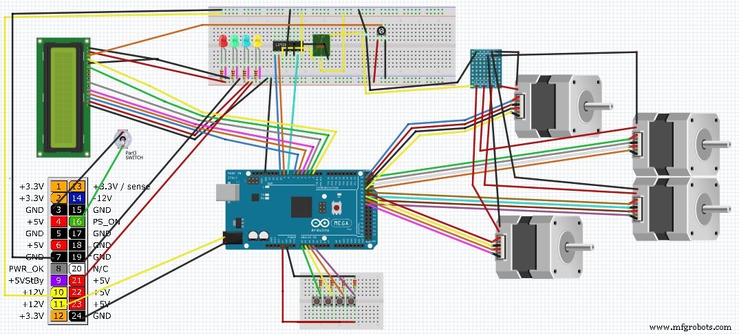
回路図
This is a complete Diagram of the system. It includes, ATX power supply, motors,LCD,LEDs, lights and controller 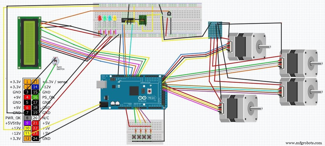
製造プロセス