


ArduinoおよびHC-12長距離無線通信モジュール
このArduinoチュートリアルでは、最大1.8kmの距離で複数のArduinoボード間で長距離無線通信を行うことができるHC-12無線シリアル通信モジュールの使用方法を学習します。詳細については、次のビデオを見るか、以下のチュートリアルを読むことができます。
このチュートリアルでは、HC-12モジュールを接続して2つのArduino間で基本的な通信を行う方法を説明する2つの基本的な例と、最初のArduinoで加速度センサーを使用して2番目のArduinoでステッパーの位置をワイヤレスで制御する追加の例を作成しましたArduino。
まず、HC-12ワイヤレスシリアルポート通信モジュールを詳しく見てみましょう。仕様は次のとおりです。
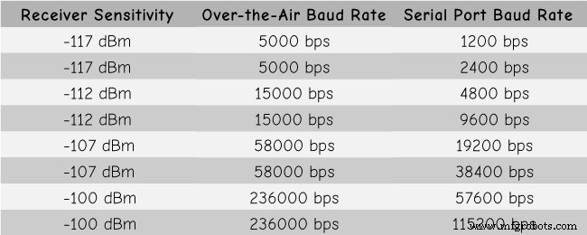
これらの値は、実際には、表に示されているように、選択したシリアルおよび無線ボーレートによって異なります。
HC-12モジュールにはマイクロコントローラーが搭載されており、実際にはユーザーがプログラムする必要はありません。モジュールの構成には、シリアルポートを使用してArduino、PC、またはその他のマイクロコントローラーから送信できるATコマンドを使用するだけです。 ATコマンドモードに入るには、モジュールの「セット」ピンを低論理レベルに設定する必要があります。
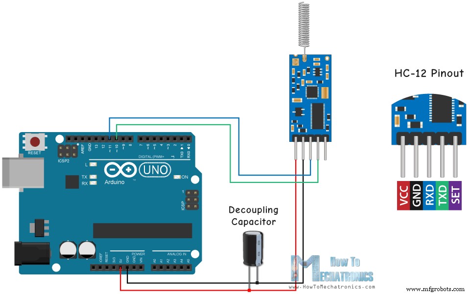
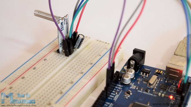
それでは、HC-12モジュールをArduinoに接続して、最初の例を作成しましょう。これが回路図です。モジュールの動作電圧は3.2V〜5.5 Vであり、より安定した作業のために、デカップリングコンデンサと外部電源を使用することをお勧めします。ただし、このチュートリアルの3つの例すべての電源としてPC USBを使用したので、問題はありませんでした。
最初のモジュールをArduinoUNOに接続し、2番目のモジュールをArduino MEGAに接続しましたが、もちろん、任意のボードを使用できます。
このArduinoチュートリアルに必要なコンポーネントは、以下のリンクから入手できます。
これが最初の例のArduinoコードで、シリアルモニターを使用した2つのモジュール間の基本的な通信です。
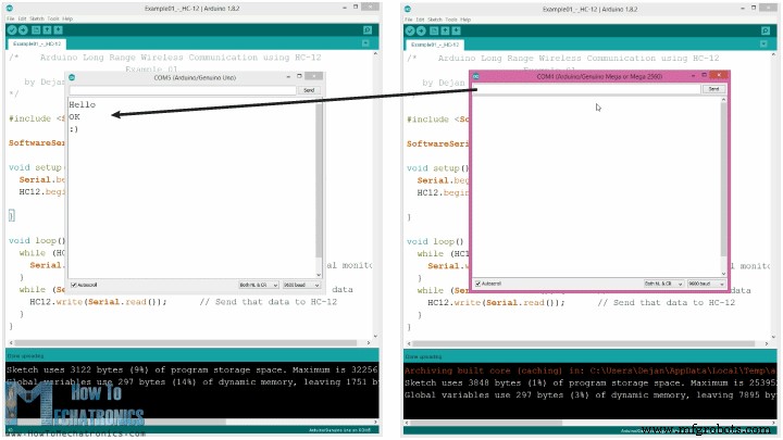
同じコードが両方のArduinoに使用されます。 2台のArduinoを2台の別々のコンピューターに接続できますが、1台のコンピューターを使用することもできます。
その場合、最初のArduinoをコンピューターに接続したら、モデルとCOMポートを選択し、コードをArduinoにアップロードする必要があります。次に、2番目のArduinoを接続し、2番目のArduinoが接続されている他のCOMポートを選択できるようにするために、Arduino IDEを再度起動して、同じコードをアップロードする必要があります。
したがって、2つのArduino IDEを実行したら、シリアルモニターを起動して、通信が正しく機能するかどうかをテストできます。シリアルモニターに入力したものはすべて、一方から他方のArduinoに送信されます。
コードの仕組み: したがって、シリアルモニターに何かを入力して[送信]ボタンをクリックすると、最初のArduinoでSerial.available()関数のwhileループが真になり、HC12.write()関数を使用してデータを送信します。 HC-12モジュールへのシリアルモニター。このモジュールはデータをワイヤレスで2番目のHC-12モジュールに転送するため、2番目のArduinoでHC12.available()関数のwhileループが真になり、Serial.write()関数を使用してデータがシリアルモニター。
ATコマンドの送信とモジュールパラメータの設定に同じコードを使用できます。モジュールの「セット」ピンをグラウンドまたはArduinoの任意のデジタルピンに接続し、ピンを低論理レベルに設定するだけです。
モードに正常に移行したかどうかをテストするには、シリアルモニターに「AT」と入力すると、応答メッセージ「OK」が表示されます。合計12個のATコマンドがあり、ボーレート、チャネル、送信電力などのさまざまなパラメータを変更するために使用されます。たとえば、「AT + B38400」と入力すると、モジュールのボーレートは次のように設定されます。 38400。
1. AT –テストコマンド。
例:モジュールに「AT」を送信すると、モジュールは「OK」を返します。
2. AT + Bxxxx –シリアルポートのボーレートを変更します。
使用可能なボーレート:1200 bps、2400 bps、4800 bps、9600 bps、19200 bps、38400 bps、57600 bps、および115200bps。デフォルト:9600bps。
例:「AT + B38400」をモジュールに送信すると、モジュールは「OK+B19200」を返します。
3. AT + Cxxxx –ワイヤレス通信チャネルを001から100に変更します。
デフォルト:チャネル001、動作周波数は433.4MHz。次の各チャネルは400KHz高くなります。
例:モジュールをチャネル006に設定する場合は、「AT + C006」コマンドをモジュールに送信する必要があり、モジュールは「OK+C006」を返します。新しい動作周波数は435.4MHzになります。
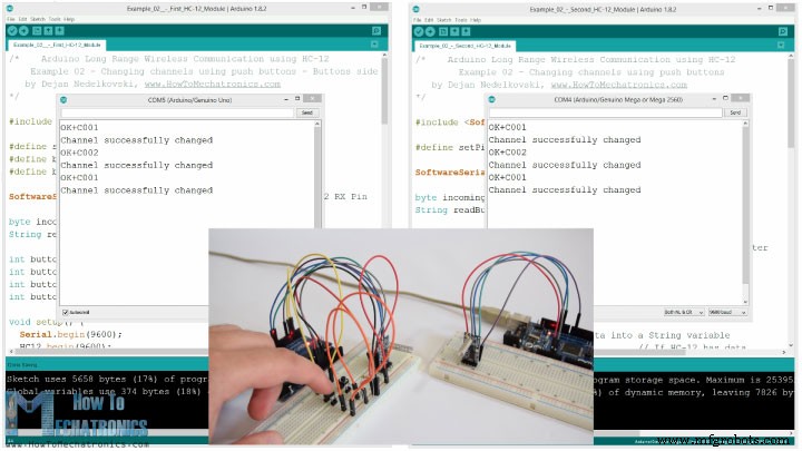
次に、2番目の例を移動しましょう。ここでは、2つのプッシュボタンを使用してさまざまな通信チャネルを選択し、着信データを保存するさまざまな方法を確認します。
注:両方のHC-12モジュールの「セット」ピンは、2つのArduinoのピン番号6に接続され、最初のArduinoの2つのボタンはピン4と3に接続されます。
最初のArduinoコード:
2番目のArduinoコード:
コードの説明:
したがって、モジュールを通常の透過モードで動作させるには、最初にピンを定義し、「セット」ピンを高論理レベルに設定する必要があります。最初のwhileループでは、受信データをString変数に格納するため、より適切に処理できます。
着信データは常に一度に1バイトになるため、たとえば、2番目のArduinoから文字列「Test123」を送信する場合、このwhileループは7回の反復を実行します。反復ごとに、HC12.read()関数を使用して、着信する各バイトまたは文字を読み取り、それを「readBuffer」という名前の文字列変数に追加します。
次に、最初のプッシュボタンを使用して通信チャネルを変更する方法を見てみましょう。したがって、HC12.print()関数を使用して最初のプッシュボタンを押すと、文字列「AT+C001」がHC-12モジュールまたは2番目のArduinoに送信されます。
この文字列が2番目のArduinoで受信されると、HC-12モジュールをATコマンドモードに設定し、同じ文字列「AT + C001」を書き込みます。これにより、モジュールは通信チャネル番号1に設定されます。
次のwhileループを使用して、チャネルが正常に変更されたかどうかをHC-12モジュールからの応答メッセージを出力します。
最初のArduinoに戻って、ATコマンドを最初のHC-12モジュールに送信するのと同じ手順を実行します。同様に、2番目のボタンを押して、通信チャネル番号2を設定します。したがって、この方法を使用すると、いつでも、どのHC-12モジュールと通信するかを選択できます。
最後に、checkATCommand()カスタム関数は、文字列が「AT」で始まるかどうかをチェックすることにより、受信したメッセージがATコマンドであるかどうかをチェックします。その場合、モジュールはATコマンドモードに入り、コマンドを実行します。
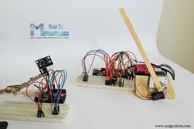
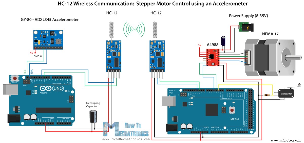
次に、3番目の例を見てみましょう。ここでは、最初のArduinoの加速度計モジュールを使用して、2番目のArduinoのステッピングモーターの位置を制御します。
この回路には、0度でのステッピングモーターの初期位置を見つけるためのマイクロスイッチも含まれています。
この例に必要なコンポーネントは、以下のリンクから入手できます。
ここで、加速度計とステッピングモーターの両方を接続して使用する方法についての詳細なチュートリアルがすでにあることに注意してください。この例では、コードのHC-12部分のみを説明します。
最初のArduino–送信機コード:
2番目のArduino–レシーバーコード:
コードの説明:
したがって、最初に、セットアップセクションでピンを定義してモジュールを初期化します。次に、加速度計のX軸とY軸の値を読み取り、0〜180度の値にマッピングします。加速度計からの値は不安定な場合や揺れる場合があるため、結果を平滑化するために、100回の読み取り値の平均値を使用しました。
さらにスムージングするために、角度の新しい値は、前の値と2だけ異なる場合にのみ送信します。
ここで、角度をHC-12モジュールに送信するときは、前に文字「s」を送信し、後に文字「e」を送信することに注意してください。これは、2番目のArduinoでデータを受信するときに役立ちます。
2番目のArduinoでは、開始マーカー「s」が来るまで待ってから、終了マーカー「e」が来るまで角度の値を読み取ります。このようにして、角度の値のみを受け取ることが確実になります。
次に、値を整数に変換し、値を0から1600ステップにマップします。これは、A4988ステッパードライバーで選択された16番目のステップの解像度に対応します。次に、ステッピングモーターを現在の角度まで回転させます。
これで、このArduinoチュートリアルはこれですべてです。以下のコメントセクションでお気軽に質問してください。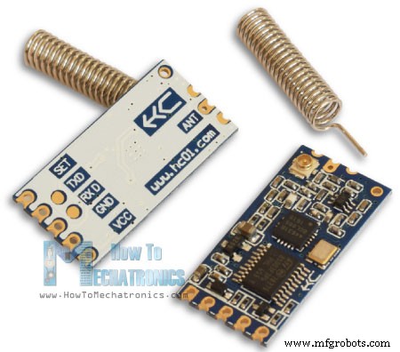
HC-12ワイヤレス通信モジュール
ArduinoとHC-12
/*    Arduino Long Range Wireless Communication using HC-12
                      Example 01
   by Dejan Nedelkovski, www.HowToMechatronics.com
*/

#include <SoftwareSerial.h>

SoftwareSerial HC12(10, 11); // HC-12 TX Pin, HC-12 RX Pin

void setup() {
  Serial.begin(9600);             // Serial port to computer
  HC12.begin(9600);               // Serial port to HC12

}

void loop() {
  while (HC12.available()) {        // If HC-12 has data
    Serial.write(HC12.read());      // Send the data to Serial monitor
  }
  while (Serial.available()) {      // If Serial monitor has data
    HC12.write(Serial.read());      // Send that data to HC-12
  }
}Code language: Arduino (arduino)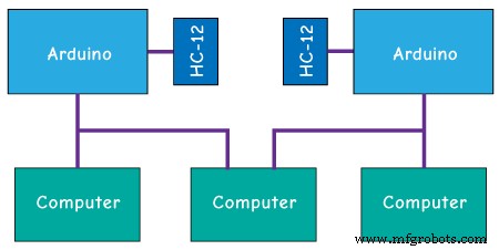
ATコマンド:
/*    Arduino Long Range Wireless Communication using HC-12
    Example 02 - Changing channels using push buttons - Buttons side
   by Dejan Nedelkovski, www.HowToMechatronics.com
*/

#include <SoftwareSerial.h>

#define setPin 6
#define button1 4
#define button2 3

SoftwareSerial HC12(10, 11);         // HC-12 TX Pin, HC-12 RX Pin

byte incomingByte;
String readBuffer = "";

int button1State = 0;
int button1Pressed = 0;
int button2State = 0;
int button2Pressed = 0;

void setup() {
  Serial.begin(9600);                   // Open serial port to computer
  HC12.begin(9600);                     // Open serial port to HC12
  pinMode(setPin, OUTPUT);
  pinMode(button1, INPUT);
  pinMode(button2, INPUT);
  digitalWrite(setPin, HIGH);           // HC-12 normal, transparent mode
}

void loop() {
  // ==== Storing the incoming data into a String variable
  while (HC12.available()) {             // If HC-12 has data
    incomingByte = HC12.read();          // Store each icoming byte from HC-12
    readBuffer += char(incomingByte);    // Add each byte to ReadBuffer string variable
  }
  delay(100);
  // ==== Sending data from one HC-12 to another via the Serial Monitor
  while (Serial.available()) {
    HC12.write(Serial.read());
  }

  // ==== If button 1 is pressed, set the channel 01
  button1State = digitalRead(button1);
  if (button1State == HIGH & button1Pressed == LOW) {
    button1Pressed = HIGH;
    delay(20);
  }
  if (button1Pressed == HIGH) {
    HC12.print("AT+C001");               // Send the AT Command to the other module
    delay(100);
    //Set AT Command Mode
    digitalWrite(setPin, LOW);           // Set HC-12 into AT Command mode
    delay(100);                          // Wait for the HC-12 to enter AT Command mode
    HC12.print("AT+C001");               // Send AT Command to HC-12
    delay(200);
    while (HC12.available()) {           // If HC-12 has data (the AT Command response)
      Serial.write(HC12.read());         // Send the data to Serial monitor
    }
    Serial.println("Channel successfully changed");
    digitalWrite(setPin, HIGH);          // Exit AT Command mode
    button1Pressed = LOW;
  }

  // ====  If button 2 is pressed, set the channel 02
  button2State = digitalRead(button2);
  if (button2State == HIGH & button2Pressed == LOW) {
    button2Pressed = HIGH;
    delay(100);
  }
  if (button2Pressed == HIGH) {
    HC12.print("AT+C002"); // Send the AT Command to the other module
    delay(100);
    //Set AT Command Mode
    digitalWrite(setPin, LOW);           // Set HC-12 into AT Command mode
    delay(100);                          // Wait for the HC-12 to enter AT Command mode
    HC12.print("AT+C002");               // Send AT Command to HC-12
    delay(200);
    while (HC12.available()) {           // If HC-12 has data (the AT Command response)
      Serial.write(HC12.read());         // Send the data to Serial monitor
    }
    Serial.println("Channel successfully changed");
    digitalWrite(setPin, HIGH);
    button2Pressed = LOW;
  }
  checkATCommand();
  readBuffer = "";                       // Clear readBuffer
}
// ==== Custom function - Check whether we have received an AT Command via the Serial Monitor
void checkATCommand () {
  if (readBuffer.startsWith("AT")) {     // Check whether the String starts with "AT"
    digitalWrite(setPin, LOW);           // Set HC-12 into AT Command mode
    delay(200);                          // Wait for the HC-12 to enter AT Command mode
    HC12.print(readBuffer);              // Send AT Command to HC-12
    delay(200);
    while (HC12.available()) {           // If HC-12 has data (the AT Command response)
      Serial.write(HC12.read());         // Send the data to Serial monitor
    }
    digitalWrite(setPin, HIGH);          // Exit AT Command mode
  }
}Code language: Arduino (arduino)/* Arduino Long Range Wireless Communication using HC-12
Example 02 - Changing channels using push buttons
by Dejan Nedelkovski, www.HowToMechatronics.com
*/
#include <SoftwareSerial.h>
#define setPin 6
SoftwareSerial HC12(10, 11); // HC-12 TX Pin, HC-12 RX Pin
byte incomingByte;
String readBuffer = "";
void setup() {
Serial.begin(9600); // Open serial port to computer
HC12.begin(9600); // Open serial port to HC12
pinMode(setPin, OUTPUT);
digitalWrite(setPin, HIGH); // HC-12 normal mode
}
void loop() {
// ==== Storing the incoming data into a String variable
while (HC12.available()) { // If HC-12 has data
incomingByte = HC12.read(); // Store each icoming byte from HC-12
readBuffer += char(incomingByte); // Add each byte to ReadBuffer string variable
}
delay(100);
// ==== Sending data from one HC-12 to another via the Serial Monitor
while (Serial.available()) {
HC12.write(Serial.read());
}
// === If button 1 is pressed, set channel 01
if (readBuffer == "AT+C001") {
digitalWrite(setPin, LOW); // Set HC-12 into AT Command mode
delay(100); // Wait for the HC-12 to enter AT Command mode
HC12.print(readBuffer); // Send AT Command to HC-12 ("AT+C001")
delay(200);
while (HC12.available()) { // If HC-12 has data (the AT Command response)
Serial.write(HC12.read()); // Send the data to Serial monitor
}
Serial.println("Channel successfully changed");
digitalWrite(setPin, HIGH); // Exit AT Command mode
readBuffer = "";
}
// === If button 2 is pressed, set channel 02
if (readBuffer == "AT+C002") {
digitalWrite(setPin, LOW); // Set HC-12 into AT Command mode
delay(100); // Wait for the HC-12 to enter AT Command mode
HC12.print(readBuffer); // Send AT Command to HC-12
delay(200);
while (HC12.available()) { // If HC-12 has data (the AT Command response)
Serial.write(HC12.read()); // Send the data to Serial monitor
}
Serial.println("Channel successfully changed");
digitalWrite(setPin, HIGH); // Exit AT Command mode
readBuffer = "";
}
checkATCommand();
readBuffer = ""; // Clear readBuffer
}
// ==== Custom function - Check whether we have received an AT Command via the Serial Monitor
void checkATCommand () {
if (readBuffer.startsWith("AT")) { // Check whether the String starts with "AT"
digitalWrite(setPin, LOW); // Set HC-12 into AT Command mode
delay(100); // Wait for the HC-12 to enter AT Command mode
HC12.print(readBuffer); // Send AT Command to HC-12
delay(200);
while (HC12.available()) { // If HC-12 has data (the AT Command response)
Serial.write(HC12.read()); // Send the data to Serial monitor
}
digitalWrite(setPin, HIGH); // Exit AT Command mode
}
}Code language: Arduino (arduino)// ==== Storing the incoming data into a String variable
while (HC12.available()) { // If HC-12 has data
incomingByte = HC12.read(); // Store each icoming byte from HC-12
readBuffer += char(incomingByte); // Add each byte to ReadBuffer string variable
}Code language: Arduino (arduino)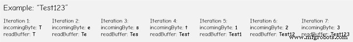
if (button1Pressed == HIGH) {
    HC12.print("AT+C001");               // Send the AT Command to the other module
    delay(100);
    //Set AT Command Mode
    digitalWrite(setPin, LOW);           // Set HC-12 into AT Command mode
    delay(100);                          // Wait for the HC-12 to enter AT Command mode
    HC12.print("AT+C001");               // Send AT Command to HC-12
    delay(200);
    while (HC12.available()) {           // If HC-12 has data (the AT Command response)
      Serial.write(HC12.read());         // Send the data to Serial monitor
    }
    Serial.println("Channel successfully changed");
    digitalWrite(setPin, HIGH);          // Exit AT Command mode
    button1Pressed = LOW;
}Code language: Arduino (arduino)// At the second Arduino
// === If button 1 is pressed, set channel 01
if (readBuffer == "AT+C001") {
digitalWrite(setPin, LOW); // Set HC-12 into AT Command mode
delay(100); // Wait for the HC-12 to enter AT Command mode
HC12.print(readBuffer); // Send AT Command to HC-12 ("AT+C001")
delay(200);
while (HC12.available()) { // If HC-12 has data (the AT Command response)
Serial.write(HC12.read()); // Send the data to Serial monitor
}
Serial.println("Channel successfully changed");
digitalWrite(setPin, HIGH); // Exit AT Command mode
readBuffer = "";
}Code language: Arduino (arduino)while (HC12.available()) { // If HC-12 has data (the AT Command response)
Serial.write(HC12.read()); // Send the data to Serial monitor
}Code language: Arduino (arduino)// ==== Custom function - Check whether we have received an AT Command via the Serial Monitor
void checkATCommand () {
if (readBuffer.startsWith("AT")) { // Check whether the String starts with "AT"
digitalWrite(setPin, LOW); // Set HC-12 into AT Command mode
delay(200); // Wait for the HC-12 to enter AT Command mode
HC12.print(readBuffer); // Send AT Command to HC-12
delay(200);
while (HC12.available()) { // If HC-12 has data (the AT Command response)
Serial.write(HC12.read()); // Send the data to Serial monitor
}
digitalWrite(setPin, HIGH); // Exit AT Command mode
}
}Code language: Arduino (arduino) HC-12ワイヤレス通信:加速度計を使用したステッピングモーター制御
/*   Arduino Long Range Wireless Communication using HC-12
     Example 03 - Stepper Motor Control using Accelerometer - Transmitter, Accelerometer
    by Dejan Nedelkovski, www.HowToMechatronics.com
*/

#include <SoftwareSerial.h>
#include <Wire.h>

SoftwareSerial HC12(10, 11); // HC-12 TX Pin, HC-12 RX Pin

float angle;
int lastAngle = 0;
int count = 0;
int angleSum = 0;

//--- Accelerometer Register Addresses
#define Power_Register 0x2D
#define X_Axis_Register_DATAX0 0x32 // Hexadecima address for the DATAX0 internal register.
#define X_Axis_Register_DATAX1 0x33 // Hexadecima address for the DATAX1 internal register.
#define Y_Axis_Register_DATAY0 0x34
#define Y_Axis_Register_DATAY1 0x35
#define Z_Axis_Register_DATAZ0 0x36
#define Z_Axis_Register_DATAZ1 0x37
int ADXAddress = 0x53;  //Device address in which is also included the 8th bit for selecting the mode, read in this case.
int X0, X1, X_out;
int Y0, Y1, Y_out;
int Z1, Z0, Z_out;
float Xa, Ya, Za;

void setup() {
  HC12.begin(9600);               // Open serial port to HC12
  Wire.begin(); // Initiate the Wire library
  Serial.begin(9600);
  delay(100);

  Wire.beginTransmission(ADXAddress);
  Wire.write(Power_Register); // Power_CTL Register
  // Enable measurement
  Wire.write(8); // Bit D3 High for measuring enable (0000 1000)
  Wire.endTransmission();
}
void loop() {
  // X-axis
  Wire.beginTransmission(ADXAddress); // Begin transmission to the Sensor
  //Ask the particular registers for data
  Wire.write(X_Axis_Register_DATAX0);
  Wire.write(X_Axis_Register_DATAX1);
  Wire.endTransmission(); // Ends the transmission and transmits the data from the two registers
  Wire.requestFrom(ADXAddress, 2); // Request the transmitted two bytes from the two registers
  if (Wire.available() <= 2) { //
    X0 = Wire.read(); // Reads the data from the register
    X1 = Wire.read();
    /* Converting the raw data of the X-Axis into X-Axis Acceleration
      - The output data is Two's complement
      - X0 as the least significant byte
      - X1 as the most significant byte */
    X1 = X1 << 8;
    X_out = X0 + X1;
    Xa = X_out / 256.0; // Xa = output value from -1 to +1, Gravity acceleration acting on the X-Axis
  }
  //Serial.print("Xa= ");
  //Serial.println(X_out);

  // Y-Axis
  Wire.beginTransmission(ADXAddress);
  Wire.write(Y_Axis_Register_DATAY0);
  Wire.write(Y_Axis_Register_DATAY1);
  Wire.endTransmission();
  Wire.requestFrom(ADXAddress, 2);
  if (Wire.available() <= 2) {
    Y0 = Wire.read();
    Y1 = Wire.read();
    Y1 = Y1 << 8;
    Y_out = Y0 + Y1;
    Ya = Y_out / 256.0;
  }

  // Combine X and Y values for getting the angle value from 0 to 180 degrees
  if (Y_out > 0) {
    angle = map(Y_out, 0, 256, 90, 0);
  }
  else if (Y_out < 0) {
    angle = map(Y_out, 256, 0, 90, 0);
    angle = 90 - angle;
  }
  if (X_out < 0 & Y_out < 0) {
    angle = 180;
  }
  if (X_out < 0 & Y_out >0) {
    angle = 0;
  }

  // float to int
  int angleInt = int(angle);
  // Makes 100 accelerometer readings and sends the average for smoother result
  angleSum = angleSum + angleInt;
  count++;
  if (count >= 100) {
    angleInt = angleSum / 100;
    angleSum = 0;
    count = 0;
    // Some more smoothing of acceleromter reading - sends the new angle only if it differes from the previous one by +-2
    if (angleInt > lastAngle + 2 || angleInt < lastAngle - 2) {
      Serial.println(angleInt);
      String angleString = String(angleInt);
      //sends the angle value with start marker "s" and end marker "e"
      HC12.print("s" + angleString + "e");
      delay(10);
      lastAngle = angleInt;
      angleSum = 0;
      count = 0;
    }
  }
}
Code language: Arduino (arduino)/* Arduino Long Range Wireless Communication using HC-12
Example 03 - Stepper Motor Control using Accelerometer - Receiver, Stepper Motor
by Dejan Nedelkovski, www.HowToMechatronics.com
*/
#include <SoftwareSerial.h>
SoftwareSerial HC12(10, 11); // HC-12 TX Pin, HC-12 RX Pin
char incomingByte;
String readBuffer = "";
// defines pins numbers
const int dirPin = 4;
const int stepPin = 3;
const int button = 2;
int currentAngle = 0;
int lastAngle = 0;
int rotate = 0;
void setup() {
Serial.begin(9600); // Open serial port to computer
HC12.begin(9600); // Open serial port to HC12
// Sets the two pins as Outputs
pinMode(dirPin, OUTPUT);
pinMode(stepPin, OUTPUT);
// Microswitch input, with internal pull-up resistor activated
pinMode(button, INPUT_PULLUP);
delay(10);
digitalWrite(dirPin, HIGH);
boolean startingPosition = true;
while (startingPosition) {
digitalWrite(stepPin, HIGH);
delayMicroseconds(200);
digitalWrite(stepPin, LOW);
delayMicroseconds(200);
if (digitalRead(button) == LOW) {
startingPosition = false;
}
}
delay(100);
}
void loop() {
readBuffer = "";
boolean start = false;
// Reads the incoming angle
while (HC12.available()) { // If HC-12 has data
incomingByte = HC12.read(); // Store each icoming byte from HC-12
delay(5);
// Reads the data between the start "s" and end marker "e"
if (start == true) {
if (incomingByte != 'e') {
readBuffer += char(incomingByte); // Add each byte to ReadBuffer string variable
}
else {
start = false;
}
}
// Checks whether the received message statrs with the start marker "s"
else if ( incomingByte == 's') {
start = true; // If true start reading the message
}
}
// Converts the string into integer
currentAngle = readBuffer.toInt();
// Makes sure it uses angles between 0 and 180
if (currentAngle > 0 && currentAngle < 180) {
// Convert angle value to steps (depending on the selected step resolution)
// A cycle = 200 steps, 180deg = 100 steps ; Resolution: Sixteenth step x16
currentAngle = map(currentAngle, 0, 180, 0, 1600);
//Serial.println(currentAngle); // Prints the angle on the serial monitor
digitalWrite(dirPin, LOW); // Enables the motor to move in a particular direction
// Rotates the motor the amount of steps that differs from the previous positon
if (currentAngle != lastAngle) {
if (currentAngle > lastAngle) {
rotate = currentAngle - lastAngle;
for (int x = 0; x < rotate; x++) {
digitalWrite(stepPin, HIGH);
delayMicroseconds(400);
digitalWrite(stepPin, LOW);
delayMicroseconds(400);
}
}
// rotate the other way
if (currentAngle < lastAngle) {
rotate = lastAngle - currentAngle;
digitalWrite(dirPin, HIGH); //Changes the rotations direction
for (int x = 0; x < rotate; x++) {
digitalWrite(stepPin, HIGH);
delayMicroseconds(400);
digitalWrite(stepPin, LOW);
delayMicroseconds(400);
}
}
}
lastAngle = currentAngle; // Remembers the current/ last positon
}
}Code language: Arduino (arduino)// Makes 100 accelerometer readings and sends the average for smoother result
angleSum = angleSum + angleInt;
count++;
if (count >= 100) {
angleInt = angleSum / 100;
angleSum = 0;
count = 0;
// Some more smoothing of acceleromter reading - sends the new angle only if it differes from the previous one by +-2
if (angleInt > lastAngle + 2 || angleInt < lastAngle - 2) {
Serial.println(angleInt);
String angleString = String(angleInt);
//sends the angle value with start marker "s" and end marker "e"
HC12.print("s" + angleString + "e");
delay(10);
lastAngle = angleInt;
angleSum = 0;
count = 0;
}
}Code language: Arduino (arduino)// Reads the incoming angle
while (HC12.available()) { // If HC-12 has data
incomingByte = HC12.read(); // Store each icoming byte from HC-12
delay(5);
// Reads the data between the start "s" and end marker "e"
if (start == true) {
if (incomingByte != 'e') {
readBuffer += char(incomingByte); // Add each byte to ReadBuffer string variable
}
else {
start = false;
}
}
// Checks whether the received message statrs with the start marker "s"
else if ( incomingByte == 's') {
start = true; // If true start reading the message
}
}Code language: Arduino (arduino)
製造プロセス