


廃熱回収技術
廃熱回収技術
廃熱は、プロセスを出て大気に入る空気、排気ガス、および/またはプロセス製品の廃棄物の流れに関連するエネルギーです。さまざまな過程で発生し、実用化されずに失われたり、大気中に浪費されたりするエネルギーです。これは、経済的な方法で有用な目的のためにエネルギーの一部を回収できるようにするのに十分な高温でプロセスから排除されるエネルギーです。
廃熱の定義では、熱を運ぶ廃棄物の流れが最終的に大気または地下水と混合し、これらの流れに含まれるエネルギーが有用なエネルギーとして利用できなくなることを意味します。環境による廃棄物エネルギーの吸収は、しばしば熱汚染と呼ばれます。
廃熱の回収は、さまざまな廃熱回収(WHR)テクノロジーを介して実行でき、貴重なエネルギー源を提供し、全体的なエネルギー消費を削減します。利用可能で、廃熱の回収と回収に使用できるWHRテクノロジーがいくつかあります。
工業プロセスで使用されるかなりの量のエネルギーは、排気ガス、空気の流れ、およびプロセスを出る液体/固体の形で熱として浪費されます。すべての廃熱を回収することは、技術的および経済的に実現可能ではありません。 WHRテクノロジーの使用の増加は、温室効果ガス(GHG)排出量の削減にも役立ちます。
WHRテクノロジーは、ガス、液体、または固体を使用するプロセスからの廃熱を捕捉して、追加のエネルギー源としてシステムに戻すことで構成されます。エネルギー源は、追加の熱を生成したり、電気的および機械的な電力を生成したりするために使用できます。廃熱はどの温度でも排出できます。通常、廃熱の温度が高いほど、廃熱の質が高くなり、WHRプロセスの最適化が容易になります。したがって、プロセスから最大の可能性のある回収可能な熱の最大量を発見し、WHRシステムから最大の効率を確実に達成することが重要です
廃熱の発生源には、通常、製品、機器、およびプロセスからの伝導、対流、および放射によって伝達される熱損失と、燃焼プロセスから放出される熱が含まれます。熱損失は、(i)高温熱、(ii)中温熱、(iii)低温熱に分類できます。 WHRテクノロジーは、達成可能なWHRの最適な効率を実現するために、廃熱のタイプごとに利用できます。
高温WHRは、400℃を超える温度での廃熱の回収で構成され、中温の廃熱範囲は100℃から400℃であり、低温の廃熱範囲は100℃未満の温度用です。高温範囲の廃熱は直接燃焼プロセスから、中温範囲は燃焼ユニットの排気から、低温範囲はプロセスユニットの部品、製品、設備から発生します。
廃熱の種類と発生源に応じて、またどの廃熱回収システムを使用できるかを正当化するために、プロセスから回収可能な熱の量とグレードを調べることが不可欠です。廃熱の定量化に使用される3つの重要なパラメータがあります。これらのパラメータは、(i)量、(ii)品質、および(iii)一時的な可用性です。
利用可能な廃熱の量または量は、式Q =V x d x Cp x(T1-T2)を使用して計算できます。ここで、Qは熱量、Vは熱を運ぶ物質の流量、dは物質の密度、Cpは物質の比熱、(T1-T2)は物質の温度差です。システムの出口(T2)の最終最高温度と入口(T1)の初期温度。利用可能な廃熱の量は、廃液ストリームのエンタルピーフローで表すこともでき、次の式で与えられます。H =m x hここで、Hは廃液ストリームの総エンタルピー率、mは廃液ストリームの質量流量です。 hは、廃棄物の流れの特定のエンタルピーです。
品質は、廃棄物の流れの温度で大まかに表すことができます。温度が高いほど、回収に利用できる廃熱が多くなります。機械やコンデンサーからの冷却水など、低温源からのWHRは一般にやや難しく、通常はヒートポンプを使用して温度を回復に適した温度に上げる必要があります。
時間的利用可能性は、必要なときに廃熱を利用できるかどうかの尺度です。廃熱の利用可能性を最終負荷に一致させることは、WHRの有効性における重要な考慮事項です。したがって、廃熱の有用性は、利用可能な量だけでなく、その品質が潜在的な負荷の要件に適合するかどうか、および必要なときに利用できるかどうか(一時的な利用可能性)にも依存します。
費用対効果の高いWHRと再利用には、十分な品質、量、時間的可用性のある廃熱源の特定と、回収された廃熱を再利用できる暖房負荷が含まれます。廃熱を再利用できる低温から中温の範囲にはいくつかのプロセスがあります。これらのプロセスは、さまざまな業界で使用されています。たとえば、特定の蒸留操作は、「オーバーヘッド」蒸留蒸気を機械的に再圧縮するオープンループヒートポンプシステムに理想的です。この蒸気は、リボイラーで凝縮され、蒸留カラムの「ボトム」生成物を蒸発させます。これらのアプリケーションは通常、小さな温度差を伴い、燃料燃焼を使用してリボイラーを加熱し、冷却塔を使用して留出物の熱を排除するよりも費用効果が高いことがよくあります。
WHRの実現可能性を評価するには、廃熱源と、熱が伝達されるストリームの特性を評価する必要があります。決定する必要のある重要な廃熱ストリームパラメータには、(i)熱量、(ii)熱温度/品質、(iii)組成、(iv)最低許容温度、および(v)運転スケジュール、可用性、およびその他のロジスティクスが含まれます。 。これらのパラメータにより、ストリームの質と量の分析が可能になり、考えられる材料/設計上の制限についての洞察も得られます。一例として、熱伝達媒体の腐食は、ストリームの質と量が許容できる場合でも、WHRではかなり懸念されます。
WHRオプションとテクノロジー
WHRのアプローチには、(i)気体および/または液体間の熱の伝達、(ii)炉に入る負荷への熱の伝達、(iii)機械的および/または電力の生成、または(iv)廃熱の使用が含まれます。暖房または冷房設備用のヒートポンプ。 WHRテクノロジーの用語は、業界によって異なることがよくあります。主なWHRテクノロジーを以下に説明します。
熱交換器
熱交換器は通常、燃焼排気ガスから炉に入る燃焼空気に熱を伝達するために使用されます。予熱された燃焼用空気が炉に入る温度が高いため、燃料から供給されるエネルギーが少なくなります。空気予熱に使用される一般的な技術には、復熱装置、炉再生器、バーナー再生器、回転式再生器、およびパッシブ空気予熱器が含まれます。
レキュペレーター –復熱装置は、中温から高温の用途で排気ガスの廃熱を回収します。復熱装置は、放射、対流、またはその2つの組み合わせに基づくことができます。
単純な放射線復熱装置は、2つの同心の長さのダクトで構成されています。高温の廃ガスは内部ダクトを通過し、熱伝達は主に壁と外殻の冷たい流入空気に放射されます。次に、予熱されたシェル空気は炉のバーナーに移動します。対流式またはチューブ式の復熱装置(熱交換器)は、大きなシェルに含まれる比較的小さな直径のチューブに高温ガスを通過させます。入ってくる燃焼用空気はシェルに入り、チューブの周りで邪魔され、排ガスから熱を奪います。別の代替手段は、放射/対流復熱装置の組み合わせです。このシステムには、熱伝達効果を最大化するために、輻射セクションとそれに続く対流セクションが含まれています。
復熱装置は、金属またはセラミック材料で構成されています。金属製の復熱装置は、1100℃未満の温度のアプリケーションで使用されますが、高温での熱回収は、セラミックチューブの復熱装置に適しています。これらは、1550℃の高温側温度と約1000℃の低温側温度で動作できます。
再生器 –再生器には、(i)炉再生器、および(ii)回転再生器またはヒートホイールの2つのタイプがあります。炉再生炉の場合、再生炉は2つのレンガチェッカー作業室で構成されており、高温と低温の空気が交互に流れます。燃焼排気が1つのチャンバーを通過すると、レンガが燃焼ガスから熱を吸収し、温度が上昇します。次に、流入する燃焼空気がホットチェッカーワークを通過するように空気の流れを調整します。ホットチェッカーワークは、炉に入る燃焼空気に熱を伝達します。 2つのチャンバーは、一方が排気ガスから熱を吸収し、もう一方が燃焼用空気に熱を伝達するように使用されます。一定時間後に気流の方向が変わります。再生器は、コークス炉で最も頻繁に使用され、歴史的には、以前は製鋼に使用されていた平炉で使用されていました。再生器は、製鉄で使用されるストーブに供給される熱風を予熱するためにも使用されます。ただし、ストーブの再生器は熱回収アプリケーションではなく、ガス燃焼から放出された熱を熱風に伝達する手段にすぎません。再生システムは、排気が汚れている高温アプリケーションに特に適しています。炉再生機の大きな欠点の1つは、サイズが大きく、資本コストが高いことです。
回転式再生器の場合、多孔質媒体に熱を蓄え、再生器を通る高温ガスと低温ガスの流れを交互にすることで熱伝達が促進されるという点で、固定式再生器と同様に動作します。回転式再生器は、空気予熱器およびヒートホイールと呼ばれることもあります。それらは、2つの平行なパイプにまたがって配置された回転する多孔質ディスクを使用します。1つは高温の廃ガスを含み、もう1つは低温のガスを含みます。高熱容量の材料で構成されたディスクは、2つのパイプ間を回転し、高温ガスパイプから低温ガスパイプに熱を伝達します。ヒートホイールは、高温によって生じる熱応力のため、一般に低温および中温の用途に制限されています。 2つのパイプ間の大きな温度差は、膨張差と大きな変形を引き起こし、パイプホイールのエアシールの完全性を損なう可能性があります。場合によっては、セラミックホイールを高温用途に使用できます。ヒートホイールのもう1つの課題は、汚染物質がホイールの多孔質材料で輸送される可能性があるため、2つのガスストリーム間の相互汚染を防ぐことです。
ヒートホイールの利点の1つは、クリーンなガス流から水分と熱を回収するように設計できることです。吸湿性材料で設計されている場合、水分は一方のパイプからもう一方のパイプに移動する可能性があります。これにより、ヒートホイールは、特に高温多湿の空気が熱と湿気を冷たい空気に伝達する空調アプリケーションで役立ちます。暖房および空調システムでの主な用途に加えて、ヒートホイールは中温用途でも限られた範囲で使用されます。
パッシブエア予熱器 –パッシブエア予熱器は、2つのガスストリーム間の相互汚染を防止する低温から中温の用途向けのガス間熱回収装置です。パッシブ予熱器には、(i)プレートタイプと(ii)ヒートパイプの2つのタイプがあります。
プレートタイプの交換器は、高温ガス流と低温ガス流用に別々のチャネルを作成する複数の平行なプレートで構成されています。ホットフローとコールドフローがプレート間で交互に発生し、熱伝達のためのかなりの領域が可能になります。これらのシステムは、ヒートホイールに比べて汚染の影響を受けにくいですが、多くの場合、かさばり、コストが高く、汚れの問題の影響を受けやすくなっています。
ヒートパイプ熱交換器は、端が密閉された複数のパイプで構成されています。各パイプには、パイプの高温端と低温端の間の作動油の移動を容易にする毛細管芯構造が含まれています。この熱交換器では、高温ガスがヒートパイプの一端を通過し、パイプ内の作動油が蒸発します。パイプに沿った圧力勾配により、高温の蒸気がパイプのもう一方の端に移動し、そこで蒸気が凝縮して熱を低温のガスに伝達します。次に、凝縮液は毛細管現象を介してパイプの高温側に戻ります。
再生/回復バーナー –これらのバーナーには、再生システムまたは回復システムが組み込まれています。これらは、スタンドアロンの再生炉や復熱装置よりも設計と構造がシンプルでコンパクトです。これらのシステムは、周囲の空気で動作するバーナーと比較して、エネルギー効率を向上させます。自己回復型バーナーは、バーナー本体の設計の一部として熱交換面を組み込んで、本体を通過して戻る煙道ガスからエネルギーを回収します。自己再生式バーナーは、排気ガスをバーナー本体から耐火媒体ケースに送り、再生炉と同じようにペアで動作します。通常、回生バーナーシステムは、スタンドアロンユニットよりも熱交換面積が少なく、回生バーナーシステムの質量は小さくなります。したがって、エネルギー回収率は低くなりますが、コストが低く、後付けが容易なため、エネルギー回収の魅力的なオプションになります。
フィン付きチューブ熱交換器/エコノマイザー –フィン付きチューブ熱交換器は、液体を加熱するための低温から中温の排気ガスから熱を回収するために使用されます。フィン付きチューブは、表面積と熱伝達率を最大化するフィンが取り付けられた丸いパイプで構成されています。液体はチューブを通って流れ、チューブを横切って流れる高温ガスから熱を受け取ります。ボイラーの排気ガスが給水の予熱に使用されるフィン付きチューブ交換器は、一般にボイラーの「エコノマイザー」と呼ばれます。
廃熱ボイラー –廃熱ボイラー(WHB)は、中高温の排気ガスを使用して蒸気を生成する水管ボイラーです。 WHBはさまざまな容量で利用可能であり、1500 cum/hourから150万cum/hourまでのガス摂取を可能にします。廃熱が所望のレベルの蒸気を生成するのに十分でない場合、通常、補助バーナーまたはアフターバーナーが追加されて、より高い蒸気出力を達成します。蒸気は、プロセス加熱または発電に使用できます。過熱蒸気の生成には、通常、システムに外部過熱器を追加する必要があります。
負荷の予熱
負荷の予熱とは、システムから出る廃熱を使用して、システムに入る負荷を予熱するためのあらゆる取り組みを指します。最も一般的な例は、ボイラー給水の予熱です。この場合、エコノマイザーは、高温の燃焼排気ガスからボイラーに入る水に熱を伝達します。他のアプリケーションでは、燃焼排気ガスと炉に入る固体材料の間の直接熱伝達を利用します。
ボイラー給水の予熱は標準的な方法ですが、直接燃焼システムで溶融する前の材料の負荷予熱はそれほど広く使用されていません。これは、製品の品質管理の難しさ、環境排出に関連する問題、高度な炉の負荷/熱回収システムの構築の複雑さとコストの増加など、さまざまな理由によるものです。それにもかかわらず、近年、負荷予熱による熱回収が注目されています。さまざまな負荷予熱炉で利用可能な技術と障壁は、炉のタイプと問題の負荷によって大幅に異なります。
低温エネルギー回収オプションとテクノロジー
経済的には低温WHRの実現可能性が制限されることがよくありますが、低品位の廃熱を費用効果の高い方法で回収して使用できるアプリケーションがいくつかあります。 40℃から200℃の範囲で大量の廃熱が利用可能であり、その回収と使用には固有の課題があり、低温WHRの個別の詳細な調査が必要です。
産業廃熱のほとんどは低温範囲にあります。たとえば、ボイラーなどの燃焼システムでは、約150℃から180℃のガスを排出する回収技術が頻繁に使用されます。また、工業用冷却水や冷却空気には大量の廃熱が見られます。たとえば、空気圧縮機の冷却だけでも、年間かなりの量の廃熱が発生します。日本のある統合鉄鋼プラント(ISP)は、わずか98℃の冷却水を使用して3.5MWの容量の発電所を設置することに成功しました。
燃焼排気ガスの場合、ガスに含まれる水蒸気を低温に冷却するとかなりの熱を回収できます。排気ガス中の水が熱交換器の表面に腐食性物質を凝縮して堆積させるのを防ぐために、120℃から150℃前後の最低温度制限がしばしば採用されます。ただし、煙道ガスをさらに冷却すると、気化潜熱を回収できるため、熱回収率が大幅に向上します。潜熱は、排気ガスに含まれるエネルギーのかなりの部分を占めています。凝縮点より下の排気ガスを冷却しながら化学的攻撃を最小限に抑えることができる技術は、蒸発潜熱を回収することによってエネルギー効率を大幅に向上させることができます。図1は、さまざまなスタック出口温度でのエネルギー回収を示しています。ガスを150℃から60℃に冷却すると、効率が3%向上します。ガスをさらに38℃まで冷却すると、潜熱の一部が捕捉され、効率が11%向上します。
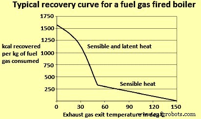
図1さまざまなスタック出口温度でのエネルギー回収
低温熱回収が直面する3つの課題があります。これらの課題は以下のとおりです。
- 熱交換器の表面に腐食があります。排気ガスに含まれる水蒸気が冷えると、その一部が凝縮して熱交換器の表面に腐食性の固体や液体を堆積させます。熱交換器は、これらの腐食性堆積物への暴露に耐えるように設計されています。これには通常、高度な材料を使用するか、熱交換器のコンポーネントを頻繁に交換する必要がありますが、これは多くの場合不経済です。
- 熱伝達には大きな熱交換面が必要です。熱伝達率は、熱交換材料の熱伝導率、2つの流体ストリーム間の温度差、および熱交換器の表面積の関数です。低温廃熱は2つの流体ストリーム間の温度勾配が小さいため、熱伝達にはより大きな表面積が必要です。これは熱交換器の経済性を制限します。
- 低温熱の要件が必要です。低温範囲で熱を回収することは、プラントで低温熱が必要な場合にのみ意味があります。潜在的な最終用途は、低温プロセス加熱です。他のオプションには、ヒートポンプを使用して熱をより高い温度に「アップグレード」し、より高い温度を必要とする負荷に対応することが含まれます。また、低温発電技術は徐々に出現しています。
低温熱交換技術
ガスを露点温度以下に冷却して低温廃熱を回収できる低温熱交換技術が利用可能です。技術オプションには、ディープエコノマイザー、間接接触凝縮回収、直接接触凝縮回収、および最近開発された輸送膜凝縮器が含まれます。これらの技術の商業化は、コストが高く、施設が回収された熱の最終用途を欠いているために制限されています。施設に廃熱の最終用途がない場合は、ヒートポンプや低温発電などの他の回収手段が使用されます。これらのテクノロジーは、経済的制約によって制限されることもよくあります。
ディープエコノマイザー –ディープエコノマイザーは、排気ガスを約70℃に冷却し、その表面に堆積する酸性凝縮物に耐えるように設計されています。エコノマイザーの設計には、さまざまな選択肢があります。エコノマイザーのコールドエンドに「使い捨て」セクションを設置することができます。コールドエンドのパイプは時間の経過とともに劣化するため、頻繁に交換する必要があります。交換の頻度は、煙道ガスの組成と構成材料によって異なります。代替案の1つは、ステンレス鋼パイプを使用してエコノマイザーを設計することです。ステンレス鋼は、建設で通常使用される軟鋼よりも酸性ガスに耐えることができます。別の設計では、熱交換器の大部分にC鋼を使用していますが、酸性堆積物が発生するコールドエンドにはステンレス鋼パイプを使用しています。ガラスパイプ熱交換器(主に空気予熱器などのガスガス用途)またはテフロンなどの高度な材料の使用は、他の代替手段となる可能性があります。
間接的な接触凝縮の回復 –間接接触凝縮回収ユニットは、ガスを約40℃に冷却します。この範囲では、ガス中の水蒸気がほぼ完全に凝縮します。間接接触交換器は、シェルアンドチューブ熱交換器で構成されています。これらは、ステンレス鋼、ガラス、テフロン、またはその他の高度な材料で設計できます。
直接接触凝縮回復 –直接接触凝縮回復には、プロセスストリームと冷却液の直接混合が含まれます。このタイプの回復には、熱が伝達される分離壁が含まれないため、間接接触回復ユニットに必要な大きな熱伝達面の課題のいくつかを回避できます。このタイプの回収では、煙道ガスが熱交換器に入ると、ユニットの上部に導入された冷水によって冷却されます。加熱された水流は交換器の底から出て、外部システムに熱を供給します。直接接触凝縮の課題は、水が煙道ガス中の物質によって汚染される可能性があることです。
輸送膜コンデンサー –トランスポートメンブレンコンデンサー(TMC)は、ガス排気流の水蒸気から(水の潜熱とともに)水を取り込むための開発中の技術です。水は、露点を超える温度で煙道ガスから毛管凝縮を利用して抽出され、ボイラー給水にリサイクルされます。直接接触熱回収と同様に、TMCは煙道ガスから直接お湯を抽出します。ただし、TMCは膜を介した輸送により水を回収するため、直接接触回収のように回収水が汚染されることはありません。この技術は、天然ガス焚きボイラーのクリーンな排気流で実証されています。ただし、TMCは、より汚れた廃棄物の流れを広く実装する前に、先端材料のさらなる開発を必要としています。
ヒートポンプまたは低温廃熱のアップグレード –上記の熱交換技術には、高温から低温の最終用途への「下り坂」のエネルギーの流れが含まれます。これにより、廃熱温度が特定の暖房負荷に必要な温度よりも低い場合に、熱回収の機会が制限される可能性があります。一例として、廃熱は約35℃の温水の形で利用できますが、約85℃の温水が必要です。このような場合、ヒートポンプは、熱を目的の最終使用温度に「アップグレード」する機会を提供できます。ヒートポンプは、外部エネルギー入力を使用して、低温源からエネルギーを吸収し、高温でそれを排除するサイクルを駆動します。設計に応じて、ヒートポンプは2つの機能を果たすことができます。廃熱をより高い温度にアップグレードするか、廃熱を吸収冷却システムを駆動するためのエネルギー入力として使用することができます。ヒートポンプは、プロセス産業で見られる低温の製品ストリームに最も適しています。
必要な温度差や燃料と電気の相対的なコストによっては、熱のアップグレードが経済的な場合があります。施設の熱負荷が廃熱源よりもわずかに高い場合、追加の燃料を燃焼させて得られる場合よりも、ヒートポンプによって熱をより効率的に提供できる場合があります。成績係数(COP)は、ヒートポンプの性能の尺度であり、熱出力と仕事量から決定され、式COP =Q / Wで与えられます。ここで、Qはヒートポンプからの有効熱出力、Wは仕事量です。
ヒートポンプの実現可能性を決定する際の重要な考慮事項は、廃熱温度と温度の望ましい上昇です。使用されるサイクルのタイプと選択された作動油のタイプは、ヒートポンプが熱を受け取ったり拒否したりできる温度に影響を与えるだけでなく、達成可能な温度の最大上昇を決定します。ヒートポンプの効率は、必要な温度上昇が上がるにつれて低下します。
閉じた圧縮サイクル –クローズドコンプレッションサイクルでは、ヒートポンプを使用して冷却水の温度を下げ、抽出された熱を使用してプラントの他の場所で使用されるプロセス水の温度を上げます。ヒートポンプは、蒸発器、圧縮機、凝縮器、および膨張弁で構成されています。蒸発器では、エネルギーが廃熱源から冷媒に伝達されます。次に、冷媒はコンプレッサーに入り、そこで温度が上昇します。次に、過熱した冷媒が凝縮器に入り、ヒートシンクに熱を伝達します。最後に、冷媒は蒸発器に戻る前に膨張弁で絞られます。
オープンサイクル蒸気再圧縮 –オープンサイクル蒸気再圧縮では、圧縮を使用して廃蒸気の圧力(および結果として温度)を上げます。機械的蒸気再圧縮は機械的圧縮機を使用しますが、熱的蒸気再圧縮は蒸気エジェクターを使用するため、機械的に駆動されるのではなく熱で駆動されます
吸収ヒートポンプ –吸収ヒートポンプは、コンプレッサーがより複雑な熱駆動吸収メカニズムに置き換えられていることを除いて、閉じた圧縮サイクルと非常によく似ています。プラントのニーズに応じて、システムは複数の方法で構成できます。 1つのタイプでは、ヒートポンプは、より低い温度とより高い温度の入熱を使用して、中間レベルで熱を排除することができます(たとえば、低温熱をアップグレードします)。別のタイプでは、ヒートポンプは中温入力を使用して、1つの低温ストリームと1つの高温ストリームの熱を排除できます。この2番目のアプリケーションは、空調や冷蔵に使用できます。
発電
廃熱から電力を生成するには、通常、ボイラーからの廃熱を使用して機械的エネルギーを生成し、それが発電機を駆動します。これらのパワーサイクルは十分に開発されています。しかし、熱電や圧電発電など、熱から直接発電できる新技術が開発されています。 WHRの発電技術を検討する際に留意すべき重要な要素は、さまざまな温度での発電に対する熱力学的制限です。発電効率は廃熱源の温度に大きく依存します。一般的に、廃熱による発電は中温から高温の廃熱源に限定されてきました。ただし、代替電源サイクルの進歩により、低温での生成の実現可能性が高まる可能性があります。これらの温度での最大効率は低くなりますが、これらのスキームは廃熱から大量のエネルギーを回収するのに経済的です。
力学的エネルギーを利用して発電する3つの方法を以下に説明します。
スチームランキンサイクル –廃熱からの発電に最も頻繁に使用されるシステムは、熱を使用して蒸気を生成し、それが蒸気タービンを駆動することです。従来の蒸気ランキンサイクルは、340℃を超える温度の排気流からの廃熱回収に最も効率的なオプションです。低圧蒸気はより大きな装置を必要とするため、廃熱温度が低くなると、蒸気サイクルの費用効果は低くなります。さらに、低温廃熱は、蒸気の凝縮およびタービンブレードの侵食を防止するための要件である、蒸気を過熱するのに十分なエネルギーを提供することができない。したがって、低温熱回収アプリケーションは、蒸気と比較して沸点温度が低い流体を使用する有機ランキンサイクルまたはカリナサイクルに適しています。
有機ランキンサイクル –有機ランキンサイクル(ORC)は、蒸気ランキンサイクルと同様に動作しますが、蒸気の代わりに有機作動油を使用します。代替品には、シリコンオイル、プロパン、ハロアルカン(フレオンなど)、イソペンタン、イソブタン、p-キシレン、トルエンなどがあります。これらは、水よりも沸点が低く、蒸気圧が高くなっています。これにより、ORCは大幅に低い廃熱温度で動作することができます。流体の熱力学的特性はさまざまな温度でのサイクルの効率に影響を与えるため、最適な温度範囲は使用する流体によって異なります。水蒸気と比較して、流体はより高分子量であり、コンパクトな設計、より高い質量流量、およびより高いタービン効率を可能にします。ただし、ORCは低温で機能するため、全体的な効率は低く、凝縮器と蒸発器の温度に依存します。効率は高温蒸気発電所よりも低いですが、低温サイクルは本質的に高温サイクルよりも効率が低いことを覚えておくことが重要です。効率の限界は、2つの温度の間で動作する熱機関の可能な最大効率であるカルノー効率に従って表すことができます。 A Carnot engine operating with a heat source at 150 deg C and rejecting it at 25 deg C is only about 30 % efficient. In this light, a low efficiency in the range of 10 % to 20 % in case of ORC is a substantial percentage of theoretical efficiency, especially in comparison to other low temperature alternatives, such as piezoelectric generation, which are only 1 % efficient.
Although the economics of ORC, heat recovery need to be carefully analyzed for any given application, it is a useful alternative in those industries which do not have in-house use for additional process heat or no neighbouring plants which can make economic use of the heat.
Kalina cycle – The Kalina cycle is a variation of the Rankine cycle, using a mixture of ammonia and water as the working fluid. A key difference between single fluid cycles and cycles which use binary fluids is the temperature profile during boiling and condensation. For single fluid cycles, the temperature remains constant during boiling. As heat is transferred to the working medium (water), the water temperature slowly increases to boiling temperature, at which point the temperature remains constant until all the water has evaporated. In contrast, a binary mixture of water and ammonia (each of which has a different boiling point) increases its temperature during evaporation. This allows better thermal matching with the waste heat source and with the cooling medium in the condenser. Consequently, these systems achieve considerable greater energy efficiency. The cycle was invented in the 1980s.
Direct electrical conversion technologies
Whereas traditional power cycles involve using heat to create mechanical energy and ultimately electrical energy, new technologies are being developed which can generate electricity directly from heat. These include thermoelectric, thermionic, and piezoelectric technologies. However, these technologies are in development stage. A few have undergone some prototype testing in applications such as heat recovery in automotive vehicles.
Thermoelectric generation – Thermoelectric (TE) materials are semiconductor solids which allow direct generation of electricity when subject to a temperature differential. This technology is based on a phenomenon known as the Seebeck effect which states that when two different semiconductor materials are subject to a heat source and heat sink, a voltage is created between the two semi-conductors. Conversely, TE materials can also be used for cooling or heating by applying electricity to dissimilar semiconductors. Thermoelectric technology has existed for a long time (the thermoelectric effect was first discovered in 1821), but has seen limited use due to low efficiencies and high cost. Most TE generation systems in use have efficiencies in the range of 2 % to 5 %. These have mainly been used to power instruments on spacecraft or in very remote locations. However, recent advances in the nano-technology have enabled advanced TE materials which can achieve conversion efficiencies 15 % or higher.
In a recent study, it has been concluded that advanced TE packages are appropriate in medium to high temperature, high flow rate exhaust streams where facilities have little use for recovered waste heat. However, more development work is needed in this area. Low cost, high volume production methods for TE materials need to be developed in order to achieve this goal. Also, maintaining a high temperature differential across thin TE devices present a significant engineering challenge. Obtaining high heat transfer rates require advances in heat transfer materials and heat exchange systems with high heat transfer coefficients.
Piezo-electric power generation Piezo-electric power generation (PEPG) is an option for converting low temperature waste heat in the range of 100 deg C to 150 deg C to electrical energy. Piezo-electric technology converts mechanical energy in the form of ambient vibrations to electrical energy. A piezo-electric thin film membrane can take advantage of oscillatory gas expansion to create a voltage output. However, there are several technical challenges associated with PEPG technologies. These include (i) low efficiency (only around 1 % efficient), (ii) difficulties remain in obtaining high enough oscillatory frequencies (current devices operate at around 100 Hz, and frequencies needed are close to 1,000 Hz), (iii) high internal impedance, (iv) complex oscillatory fluid dynamics within the liquid/vapour chamber, (v) need for long term reliability and durability, and (vi) high costs.
While the conversion efficiency of PEPG technology is currently very low (1 %), there can be prospects to use PEPG cascading, in which case efficiencies can reach about 10 %. Other key issues are the costs of manufacturing piezoelectric devices, as well as the design of heat exchangers to facilitate sufficient heat transfer rates across a relatively low temperature difference.
Thermionic generation – Thermionic devices operate similar to thermo-electric devices. However, whereas thermoelectric devices operate according to the Seebeck effect, thermionic devices operate via thermionic emission. In these systems, a temperature difference drives the flow of electrons through a vacuum from a metal to a metal oxide surface. One key disadvantage of this technology is that it is limited to applications with high plying electricity to dissimilar semiconductors. Thermo-electric technology has existed for temperatures above 1,000 deg C. However, some development has enabled their use at around 100 deg C to 300 deg C range.
Thermo photo voltaic generator Thermo photo voltaic generators can be used to convert radiant energy into electricity. This technology involves a heat source, an emitter, a radiation filter, and a photo voltaic (PV) cell (like those used in solar panels). As the emitter is heated, it emits electro-magnetic radiation. The PV cell converts this radiation to electrical energy. The filter is used to pass radiation at wave-lengths which match the PV cell, while reflecting remaining energy back to the emitter. This technology can potentially enable new methods for WHR. A small number of prototype systems have been built for small burner applications and in a helicopter gas turbine.
WHR and iron and steel industry
The iron and steel industry employs several high temperature furnaces for coke, sinter, hot metal, and steel production and accounts for high energy consumption. While recovery from clean gaseous streams in the industry is common, heavily contaminated exhaust gases from coke oven, blast furnace (BF), basic oxygen furnace (BOF), and electric arc furnace (EAF) continues to present a challenge for economic WHR. Heat recovery techniques from these dirty gaseous streams are available, yet implementation has been limited due to high capital investment costs.
The steel industry has made the biggest progress in reducing its energy intensity. Such progress has been achieved by continuous casting and optimization of BF operation, and also through steel recycling and replacement of fossil fuels with recycled by-product gases (coke oven gas, blast furnace gas, and converter gas). In-situ waste heat recovery has been implemented wherever possible, for example, by recirculating hot flue gases inside the furnace where they were created to lower external energy demand, or by using hot flue gases to preheat combustion air or fuel gas. Such energy efficiency improvements still leave residual waste heat recovery opportunities, e.g. to produce steam for other parts of the process or to produce electricity.
WHR in case of steel plants is described below.
Coke production
Production of coke is an essential burden material for BF operation. Coke is produced in coke ovens, where coal is heated in an oxygen limited atmosphere. There are two methods for producing coke namely (i) the byproduct process, and (ii) the non-recovery process. In the byproduct process, chemical byproducts (crude tar, ammonia, and light oils) in the coke oven gas are recovered, while the remaining coke oven gas (COG) is cleaned and recycled within the steel plant. In the non-recovery process, the entire COG is burned in the process. The most common type of process is still the byproduct process and this is discussed below.
Byproduct cokemaking process has two areas of sensible heat loss namely (i) COG which is cooled in the gas cleaning process, and (ii) waste gas leaving the coke oven. The coke making process employs several coke oven chambers separated by heating flues. Recycled COG, and sometimes other gases such as BF gas, are used as the fuel source in the heating flue and supply heat to the oven chamber where coal carbonization takes place. As coal is carbonized in the oven chamber, gas and moisture (accounting for around 8 % to 11 % of charged coal) are driven off and leave through the pipes. The COG has a high heat content ranging from around 4000 kcal/cum to 4400 kcal/cum and hence it can be recycled for use as a fuel after undergoing a cleaning process.
The temperature of the crude COG at the oven outlet ranges from 650 deg C to 1000 deg C. At this point, the COG gas is a source of sensible heat. However, the heat is universally wasted due to the high amount of tar and other materials which can cause build up on heat exchanger surfaces. Upon leaving the oven, the COG is cooled by ammonia liquor spray followed by primary coolers. Different technologies are then used for removing tar, sulphur compounds, ammonia, and light oils. After cleaning, the COG is used as a fuel throughout the steel plant. In this arrangement, only the chemical energy of the COG is recovered when recycled, while the sensible heat is wasted.
While most of the steel plants do not employ heat recovery from COG, a limited level of heat recovery from COG is possible, as shown by the success of this practice in Japan. Coke oven facilities in Japan have successfully applied heat recovery through use of a low pressure heat transfer medium. In general, the minimum allowable temperature for the COG in the heat exchanger is around 450 deg C. At lower temperatures, tar condenses and leads to soot formation on the heat exchanger surface. Cooling to 450 deg C enables only about one third of the sensible heat to be recovered. However, it is unlikely that ISPs in other countries are going to pursue new technologies for heat recovery from crude coke oven gas. This is since ISPs are facing cost barriers with heat recovery from dirty exhaust streams. Also, the byproduct coke making process can become irrelevant in future years. It is likely that the ISPs are going to move away from the byproduct process to the non-recovery process due to environmental considerations. In the non-recovery process, the COG gas is burned within the process, and a WHB used to recover the sensible heat in the off gases.
Another source of sensible heat loss in coke ovens is the waste gases from the combustion of recycled fuel gases. The recycled fuel gases are used in the heating flue, which is adjacent to the oven chamber. Combustion of the fuel gases generates hot exhaust gases which leave the oven flue and pass through a regenerator to transfer heat to incoming combustion air and/or fuel. Waste gases leave the regenerator at temperatures averaging around 200 deg C. In some plants, the heat content of the waste gases are further recovered by use of a heat pipe or for preheating coal charge and reducing its moisture content. In this case, the temperature of the exhaust gases drops to around 60 deg C.
Production of sinter
Sintering plant consists of two major sections, sintering section and sinter cooling section. Heat recovery from both parts has been developed namely (i) from sintering section exhaust gas, and (ii) from cooling section cooling gas. There is large temperature difference depending on the position of the section. Average gas temperature in both sections is in the level of 100 deg C to 150 deg C, too low for effective heat recovery. Heat recovery is to be limited to high gas temperature zone, the final part of sintering section and primary part of cooling section, where gas temperatures of 300 deg C or higher are available. Although heat recovery zone is limited, the gas volume of sintering process is large enough for practical heat recovery.
The waste gas energy recovery system consists of hood, dust catcher, heat recovery boiler, circulation fan and de-aerator. Sintering machine exhaust gas is corrosive containing some dusts. Heat recovery is generally limited to high gas temperature zone as aggregated average temperature is low for heat recovery. At the same time, due to its corrosiveness, the gas temperature after heat recovery is to be kept above acid due point of the gas. Cooling gas is basically atmosphere air containing some dust. In case of sinter cooler, it is same as sintering machine heat recovery. Due to gas temperature distribution along with the cooler, heat recovery is limited to high gas temperature zone.
Sintering machine exhaust gas heat recovery can be categorized to circulation type and non-circulation type. In circulation type, gas after heat recovery are circulated to sintering machine as cooling gas replacement, whereas in non-circulation type, the gas after heat recovery is lead to gas treatment facility directly. Circulation type is adopted to improve heat recover efficiency.
In case of cooler heat recovery, the cooler gas is air. The cooler heat recovery system can be categorized as circulation type and non-circulation type. In case of non-circulation type, after heat recovery from hot gas zone, cooling gas is released to the atmosphere. In case of circulation type, after heat recovery from hot gas zone, cooling gas is led to cooler and reused for sinter cooling. Cooler gas temperature rises through recirculation and consequently results to higher heat recovery. On the other hand, cooling gas temperature rises up to the level of 180 deg C, cooling capability can decrease. Sinter temperature at outlet of the cooler is higher around 30 deg C in circulation type. Temperature difference is small enough and does not affect sinter plant operation. Recovered energy increases by 50 % in circulation type compared to non-circulation type. Fan power consumption is larger in case of circulation type. However, recovered power is far larger.
Hot metal production in BF
BF is one of the main units in ISPs. It converts iron ore into hot metal. Raw materials are charged from the top, including iron containing materials (lump iron ore, sinter, or pellets), additives (flux), and coke, while hot air and supplemental fuels are injected through tuyeres at the bottom of the furnace. The burden moves down through the BF and meets a rising current of hot gases. The hot air entering the BF is provided by several auxiliary hot blast stoves. In the hot blast stove, mixed gas consisting of BF gas (BFG) and COG are combusted. The heat from the combustion exhausts is transferred to a checker work regenerator. When the regenerator reaches an appropriate temperature, the flow of air is reversed and cold air is forced through the regenerator, which transfers heat to the cold air. The heated air is then injected into the furnace. The system operates according to the same principles as a regenerator used for heat recovery. However in this case, the regenerator is not a waste heat recovery unit, but rather the mechanism for transferring heat from the stove to the hot blast. Sources of off gas waste heat in BF include both the exhaust gases from the hot blast stove and the BFG leaving the BF.
There is sensible heat loss from BFG. New BFs are designed for efficient heat transfer, resulting into hot gases at the BF top in the low temperature range. The BFG is recovered for use as a fuel in blast air heating, rolling mill reheating furnaces, coke oven heating, power production, and steam generation. Since BFG has low calorific value, it is often mixed with COG or converter gas. BFG is required to be cleaned before it can be used as a fuel, and the sensible heat contained in the gas is rarely recovered. In some cases, BF operates at a sufficiently high pressure (2.5 atm or higher) to economically use a top pressure recovery turbine (TRT) for recovering of the pressure energy of the BFG. The gas is to be cleaned before entering the TRT, which is generally accomplished via wet cleaning, with the result that sensible heat of the off gas is lost. An alternative to wet cleaning technology is dry cleaning, in which the temperature of the gas entering the TRT can be raised to around 120 deg C. Dry type TRT technology is already working in several places. However, it is more expensive.
Another opportunity for WHR is from the combustion exhaust gases leaving hot blast stoves. The gases are at temperatures of around 250 deg C. The blast stove exhaust gas is relatively clean and is more compatible with heat recovery devices, making heat recovery from blast stoves a more common practice. The heat can be used to preheat combustion air and/or fuel gas. Heat exchangers used include rotary regenerators, fixed plate heat exchangers, and circulating thermal medium systems.
Production of liquid steel in BOF
BOF uses oxygen to oxidize impurities in the hot metal. Operation is semi-continuous:hot metal and scrap are charged to the furnace, oxygen is injected, fluxes are added to control erosion, and then the metal is sampled and tapped. The temperature required to melt the metal is supplied by the exothermic oxidation reaction and hence, no external heat source is needed.
The off gases from the BOF are at a high temperature. It has a high concentration of CO (carbon monoxide). Like COG and BFG, BOF gases offer opportunities for recovery of chemical energy and sensible heat. Challenges to WHR include high capital costs and the substantial maintenance problems resulting from hot dirty gases. Contaminants include iron oxides, heavy metals, SOx, NOx, and fluorides.
Various commercial methods for WHR are available. The two main methods for heat recovery are open combustion and suppressed combustion. In open combustion systems, air is introduced to the BOF gas duct to combust the CO. The heat generated is recovered with a waste heat boiler. In the suppressed combustion method, a skirt is added to the converter mouth to reduce air infiltration and combustion of the CO. The gas is then cleaned, collected, and used as a fuel. It is also possible to recover both the gas and the sensible heat via a combined boiler/suppressed combustion gas recovery system.
Liquid steel production by EAF
The steel industry has experienced significant growth in manufacture from recycled scrap via electric smelting. EAF and induction furnace are the two types of furnaces used to melt ferrous scrap for electric smelting. Out of these two, EAF is the prominent furnace. The furnace is refractory lined and typically covered by a retractable roof, through which C electrodes are lowered. Charge materials are lowered through the roof. Fluxes and alloying agents are also added to help control the quality of the material. The electrodes are then lowered to about an inch above the metal, and the current provides heat for melting the scrap. During furnace operation, several gases and particulate emissions are released, including CO, SOx, NOx, metal oxides, volatile organic compounds (VOCs), and other pollutants. Off gas temperatures at peak loads can equal anywhere from 1,350 deg C to 1,950 deg C. Exhaust gases are responsible for losses of around 20 % of the power input. Half of these losses are due to the chemical energy in the gases, while the other half is sensible heat. Additionally, around 8 % to 10 % of energy input is also lost to EAF cooling water jacket.
The most common method for heat recovery is scrap preheating, which has been widely used. The use of off gases to preheat scrap can save from 5 % to 10 % of total EAF energy consumption. Initial designs for scrap preheat required piping off gases to the charging bucket. Some of the challenges with these systems include the need to transport preheated scrap containing semi-burned non scrap materials (e.g., plastics), as well the evaporation of volatiles which create odour and environmental control problems. Alternatives to the bucket preheating system include the Consteel process, the Fuchs shaft furnace, and the Twin shell furnace. These processes have been installed at various places.
The Consteel process involves continuous charging of scrap and uses a scrap conveyer, a feeding system, and a preheater. The preheater is a refractory lined tunnel where off gases flow opposite the flow of scrap charge. Air is introduced into the preheater to burn the CO and CO2 and thus both the chemical and sensible heat in the off gas is used. An afterburner is sometimes installed to burn remaining CO and other compounds.The Fuchs shaft furnace involves a shaft immediately above the arc furnace roof. The charge is loaded via baskets in three stages. The baskets are refractory lined and designed with a seal which prevents the escape of fumes. Scrap heating is further assisted by auxiliary oxy-fuel burners. Additionally, afterburners are installed to completely combust all the CO. One additional benefit of the system is that charge acts as a dust filter, capturing around 40 % of the dust and returning it to the furnace, thus enabling slight increases in yield.
The benefits and drawbacks of scrap preheating systems depend on the specific operation. In some cases, it enables reduced electricity consumption and increased productivity. In other cases, scrap preheating systems are difficult to maintain. As EAFs become increasingly efficient and tap to tap times are reduced, scrap handling can reduce productivity and possibly create burdensome maintenance demands. In one case, the energy savings enabled by scrap preheating are reduced by about one half when tap to tap times are reduced by a third.
Power plant boilers
Boilers in ISPs normally use BFG and COG as fuel. The exhaust gas temperature for the boilers varies with the boiler’s age and the controls used. Temperatures can be fairly high (340 deg C to 450 deg C), with O2 content varying from 3 %7.5 %. The waste heat is in the form of clean, contamination-free gases and does not require further conditioning. The areas of waste heat and recovery from boilers and steam systems include (i) use of exhaust gases to preheat BFG and COG, (ii) use of low-temperature power generation if economically justifiable, (iii) preheating service water or river water for use in the plant, if possible and required, and low-pressure steam can be condensed and reused for the boiler water system instead of venting.
Reheating furnace
Reheating furnace is a key equipment of the hot rolling mills. Its function is to continuously heat billets, slabs or blooms of different sizes and grades upto 1,250 deg C. Most of the new reheat furnaces are walking beams furnaces (WBF). On the WBF, the heating is done over and under the products which are handled from charging side to discharging side by means of insulated and cooled beams (skids). A key performance criterion for reheating furnaces is heating homogeneity. 20 % to 30 % of the energy input is typically wasted divided between several thermal losses namely (i) the temperature of the exhaust gas between the combustion air recuperator and the stack is at 250 deg C to 300 deg C with natural gas fuel and higher with lower calorific value fuel, (ii) the product handling systems inside the furnace with skids and post cooling system, and (iii) wall and doors losses, hardly recoverable.
Water is used to constantly cool the skid system which is in contact with a very hot atmosphere in the furnace. This water loop typically enters at 40 deg C and is heated by 15 deg C before being directed to a dedicated cooling system.
At several places, WHR is carried out on the skid cooling system by producing steam when it is needed in the plant for other purposes. On its own, this installation reduces losses through the skid system because of the use of water cool pipes used at higher temperature. If steam is not needed by the plant then an ORC (adapted for such temperatures around 200 deg C) can be installed on the steam circuit to produce electricity. This installation has the benefit of being easily and safely operable especially with high variability of the losses because of the constant temperature brought by the water phase change. Most of the time, this technology is not installed because of long payback, and the energy contained in exhaust gases is wasted.
An electricity production system is possible to recover energy from exhaust gases. Depending on the heat source temperature, either a water-steam cycle (with low efficiency furnace) or an ORC (with better efficiency) are available. However, most of the time those technologies are not installed because of their long payback. This situation can have another solution. This solution combines heat from the skid cooling loop operated at higher pressure and temperature so as to produce a mixture of steam and water at around 215 deg C in a closed loop and heat from exhaust gases. The two heat sources are recovered separately thanks to organic heat fluid loops and then combined to form a common heat source.
The heat fluctuation from the exhaust gases (temperature and volume are modified) in case of furnace power variations (production or product variations) are balanced because of the constant temperature of the heat coming from the skid cooling system. Thus operation of the system is easy and makes the global heat source more stable especially with high fluctuations.
It is possible that the reheat furnace production can fluctuate in few minutes, which affects the heat content of exhaust gases entering the WHR system. The ORC is a rather flexible system which can accommodate such variations upto a certain point. An ORC can typically operate down to 30 % of its nominal capacity, and automatically shuts down when the heat input goes below that threshold. However, the economic aspect is affected as electricity production also decreases as well.
Heat storage solutions can be adapted to daily variations are becoming available for industrial applications and can be used in combination with an ORC to flatten its production. Oil is, for instance, is appropriate heat storage medium at that temperature level. Economic benefits need to be assessed on a case by case basis.
Waste heat from solid streams
In addition to waste heat losses from off gases, solid streams and cooling water are sources of additional sensible heat losses. Solid products and byproducts with significant waste heat losses include hot coke, hot sinter, BF slag, BOF slag, cast steel, and hot rolled steel. Though the heat from solid streams are often more difficult to recover, the heat losses are high. The sensible heat loss from coke is recovered in some plants coke dry quenching (CDQ) as an alternative to wet quenching. CDQ involves catching incandescent coke in a specially designed bucket, which is discharged into the CDQ vessel. An inert gas such as nitrogen passes over the coke and recovers its sensible heat. The hot gas is then passed through a waste heat boiler. Energy saving is in the range of 0.2 million to 0.25 million kcal per ton of coke. There have also been attempts to recover heat from other solid flows via radiant heat boilers. This was unsuccessful for BF and BOF slag, but has been commercialized for recovering heat from cast steel in a few locations in Japan and Germany.
Another option for reducing heat losses from cast steel is hot charging, in which cast products are charged to the reheating furnace while still hot. Hot charging can save about 0.12 million kcal per ton. Sensible heat loss from hot rolled steel can also be partially recovered by using water cooling. Since the final temperature of the cooling water is generally low (around 80 deg C), it can be upgraded for other heating applications with a heat pump.
製造プロセス