


廃水および水処理技術
廃水および水処理技術
安くて豊富な水は、何世紀にもわたって鉄鋼業界が当たり前と思っていた生産ユーティリティでした。しかし、現在のシナリオでは、淡水の利用可能性と消費の不均衡が拡大しているため、水資源がますます不足しているため、清潔で安全な水へのアクセスは現代社会の主要な課題の1つになっています。 (i)人口の増加と干ばつが発生しやすい地域への移住、(ii)急速な産業開発と一人当たりの水使用量の増加、(iii)人口密集地域の気象パターンの変化につながる気候変動により、水需要は増加し続けています。これにより、鉄鋼業界は新しい水制約の時代に入りました。さらに、過去30年間で、環境汚染への懸念が世界中で高まっており、これにより、より制限的な環境規制が公布されています。
鉄鋼業界では、冷却、粉塵抑制、洗浄、温度管理(熱処理)、廃棄物(灰、汚泥、スケールなど)の輸送など、さまざまな用途に大量の淡水を使用しています。水は、原料炭混合物の水分含有量を制御するための水の添加、焼結混合物のペレット化、鉄鉱石ペレットの製造中のグリーンペレットの製造、蒸気の製造、したがって電力など、いくつかの鉄鋼プラントプロセスの重要な部分です。高炉スラグ等の造粒も行います。大量の水を使用すると、大量の廃水が発生し、排出されます。鉄鋼業からの排水は、水質汚染の要因の一つとして認識されています。製鉄所のプロセスで発生する廃水には、多くの溶解および未溶解の物質や化学物質が含まれています。
鉄鋼プラントプロセスによるプロセス水の主な用途には、プロセスオフガスの冷却と洗浄、コークスとスラグの直接冷却、鋼の直接冷却と洗浄、製品のすすぎ、プロセス溶液の補給、プロセス機器の直接冷却などがあります。鉄鋼プラントで使用される水のほとんどは、処理装置の非接触冷却用です。水は蒸気や発電にも使用されます。
プロセス廃水は、プロセス、製品、副産物、または鉄鋼生産の原材料と直接接触するあらゆる廃水と定義されます。プロセス廃水には、スラグ焼入れ、機器洗浄、大気汚染防止装置、すすぎ水、および汚染された冷却水からの廃水も含まれます。衛生排水と雨水はプロセス排水とは見なされません。非接触冷却廃水は、プロセス、製品、副産物、または原材料に直接接触しない冷却水です。この廃水はプロセス廃水とは見なされません。非プロセス廃水とは、ユーティリティ廃水(水処理残留物、ボイラーブローダウン、熱回収装置からの大気汚染防止廃水、および共同発電施設から発生する水)、処理済みまたは未処理の廃水などの非プロセス操作によって生成されたものです。地下水浄化システム、基礎を構築するための脱水水、および生産プロセスに関連しないその他の廃水ストリーム。
廃水の排出とは、処理済みまたは未処理の廃水を受け入れストリームに放出することを意味します。排出は、処理プラントまたは収集システムのオーバーフローから発生する可能性があります。未処理の廃水排出は、いくつかの望ましくない状態を引き起こす可能性があります。これらには、(i)河川での酸素の枯渇と臭気の生成、(ii)病原性微生物の存在による人間の健康への悪影響、(iii)スラッジとスカムの蓄積、(iv)の成長による水域の富栄養化が含まれます。廃水には一定量の栄養素が含まれている可能性があるため、水生植物や藻類、および(v)廃水中に存在する有機化合物の分解による大量の悪臭ガスの生成。この排水の排出は、排出前に適切に処理および無害化されていない場合、その地域の水域の汚染の一因となります。したがって、廃水の処理は、工場の敷地を離れて自然の水域に排出する前に必須です。
廃水処理の方法は、環境への廃水の排出と公衆衛生への懸念によって引き起こされる悪条件に対応して最初に開発されました。鉄鋼業界の廃水処理は、廃水の性質が鉄鋼プラントのさまざまな処理ユニットとは異なる特性を持っているため、非常に複雑です。
純水は2部の水素と1部の酸素で構成されています。自然界では、水には多くの溶存不純物が含まれています。実際、水は多くの物質を溶解する能力があるため、「普遍的な溶媒」と呼ばれています。蒸留水や降雨水でさえ、通常、不純物と見なされるアンモニアなどの溶解物質が非常に低レベルで含まれているため、「完全に」純粋ではありません。地表水や地下水には溶存物質が含まれています。雨が降ると、窒素やその他のガスが吸収されます。水は地面を移動するときに、ナトリウム、カルシウム、鉄、リン、マグネシウム、硫酸塩などの物質を地球から溶解する可能性があります。
新鮮な国産の未処理または原水は、かび臭い臭いがあり、pH範囲は6.5〜8で、色は灰色がかった茶色です。未処理の水に通常見られる汚染物質は、大きく4つの基本的なクラス、すなわち(i)有機汚染物質、(ii)無機汚染物質、(iii)病原体、および(iv)その他の汚染物質に分類できます。廃水中に存在する典型的な汚染物質を以下に示します。
ソリッド –廃水中の全固形物は、溶解固形物または浮遊固形物の形をとることができます。浮遊物質は、コロイド状固体(沈降できない)または沈降性固体の形をとることができます。浮遊物質(SS)は、未処理の廃水が水生環境に排出されると、汚泥堆積物や嫌気性条件の発生につながります。総浮遊固体(TSS)には、フィルターを通過するすべての粒子が含まれます。 TSSのレベルが上がると、水域は多様な水生生物をサポートする能力を失い始めます。浮遊物質は太陽光から熱を吸収し、それによって水温が上昇し、その後溶存酸素のレベルが低下します。一部のソリッドは、フロート可能なソリッドにすることもできます。これらの浮遊可能な固形物は、通常、油またはグリースの粒子で構成され、スカムを構成します。スカムは、表面スキミング装置によって最も簡単に除去されます。
生分解性有機物 –生分解性有機物は、主にタンパク質、炭水化物、および脂肪で構成されています。生分解性有機物は、主にBOD(生物化学的酸素要求量)とCOD(化学的酸素要求量)の観点から測定されます。水質の重要な指標であるBODは、細菌やその他の生物が20℃の温度で5日間にわたって水サンプルに存在する有機物を酸化するために必要な酸素の量を測定します。 CODは、反応で完全に酸化されない一部の芳香族化合物(ベンゼン、トルエン、フェノールなど)を除いて、すべての有機炭素を測定します。 CODは化学酸化反応です。高いBODとCODは、水域の低酸素濃度に寄与し、一緒になって水域の水生生物に悪影響を及ぼします。生分解性有機物の生物学的安定化は、未処理のまま環境に排出された場合、天然酸素資源の枯渇と敗血症状態の発症につながる可能性があります。
病原体 –病原体は、病気を引き起こす、または引き起こす可能性のある微生物です。伝染病は、廃水中の病原菌によって伝染する可能性があります。
栄養素 –窒素とリンの両方は、炭素とともに、成長に不可欠な栄養素です。水生環境に排出されると、これらの栄養素は望ましくない水生生物の成長につながる可能性があります。陸地に過剰に排出されると、地下水の汚染にもつながる可能性があります。
重大な汚染物質 –これらは、未知または疑わしい発癌性、変異原性、または高い急性毒性を引き起こすという特徴を持つ有機および無機化合物です。公衆衛生上の理由と生物学的処理プロセスを保護するために、廃水中のこれらの化合物の存在を最小限に抑える必要があります。
耐火性有機物 –これらの有機物は、従来の廃水処理方法に抵抗する傾向があります。典型的な例には、界面活性剤、フェノール、および農業用農薬が含まれます。これらのいくつかは、生物学的治療プロセスに有毒である可能性があります。
重金属 –鉄鋼プラントのさまざまなユニットで生成される廃水には、重金属が含まれている可能性があります。これらの重金属は、飲料水源として使用される水域に廃水を排出する場合は除去する必要があります。重金属の存在は、農地でのバイオソリッド(安定化された廃棄物スラッジ)のリサイクルにも影響を与える可能性があります。
溶解した無機物 –カルシウム、ナトリウム、硫酸塩などの無機成分は、鉄鋼プラントの一部のユニットの廃水に存在する可能性があります。これらは、飲料水源として使用される水域に廃水が排出された場合に除去されます。
溶解した化学物質 –プロセスによっては、さまざまな溶解化学物質が廃水に存在する可能性があります。これには、汚染物質の種類、それらの濃度、流れ、および生分解性の容易さを注意深く評価する必要があります。排出される水の濃度が1リットルあたりわずか1ミリグラムであると、着色された水が発生し、水域の美的品質と透明性に影響を与える可能性があります。また、光合成にも影響を与えます。酸とアルカリは、低または高pHの状況を作り出します。一部の化学物質は、従来の処理プロセスでは分解しにくい場合があります。
化合物に由来する有機汚染物質には炭素が含まれています。これらの汚染物質は生分解性である可能性があります。つまり、汚染物質は細菌やその他の微生物によって消費される可能性があります。これらの有機物は、消費される過程で、廃水のBODとして測定できる酸素要求量を発揮します。一部の有機汚染物質(耐火有機物)は、生分解に耐性があります。無機汚染物質は生分解性ではありませんが、微生物が生きるために必要な栄養素である可能性があります。これらは通常、化合物(重大な汚染物質)または金属であり、浮遊物質または溶解した無機物として廃水中に存在します。
病原体は、細菌やウイルスなどの病気の原因となる生物であり、人間や動物の排泄物、または不適切に処理された病院の排泄物から廃水に沈着する可能性があります。廃水を回避する場合、適切な衛生状態が非常に重要です。他の不純物は熱廃棄物である可能性があります。熱廃棄物を伴う廃水排出は、流入水の流れと温度の突然の上昇を引き起こす可能性があります。熱廃棄物の典型的な発生源は、非接触冷却水(温度が河川温度を超える温水)です。ストリームの用途に応じて、ストリームの温度が上昇して使用に影響を与えるのを防ぐために、廃水の温度に制限を設けることができます。放射性廃棄物は、放射線源を使用する実験室や機器から発生する可能性があります。通常、放射性廃棄物を下水道に排出させないことをお勧めします。
さまざまな水処理プロセスには、主に3つの目的があります。つまり、(i)飲料水や生産プロセスでの使用などの特定の用途に適した、摂取源の水の固有の物理的、化学的、生物学的品質を付与および保存することです。 、(ii)環境に害を及ぼすことなく公衆を健康上のリスクから保護する廃水処理を許可すること、および(iii)水生生物の保全と開発に必要な自然環境における水の特性を付与および保存すること生命と植生、そして牛と野生動物のための飲料水の供給のため、または娯楽と美的目的のため。
水または廃水の処理は、プロセスを作成するために組み合わされるいくつかの個別の単位操作に依存します。これは、プロセス処理スキームと呼ばれることがよくあります。単位操作はすべて、比較的狭い範囲の統治原則に基づいています。飲用に浄化されるのが地面、湖、貯水池、川、または海からの水であるか、または浄化されるのが廃水(すなわち、下水または産業排水)であるかにかかわらず、同じ基盤メカニズムがプロセスに適用されます。環境への安全な排出。
従来の廃水処理技術は、環境に排出される廃水の水質を改善し、汚染された水が他の利用可能なきれいな水資源を汚染するのを防ぎます。しかし、これらの処理技術は、発電所に近いコミュニティでのさらなる有益な使用に廃水を適合させません。従来の技術のこの制限を克服し、リサイクルと再利用の慣行の普及を促進するには、廃水の水質をさらに改善できる革新的で高度な技術が必要です。
高度な処理プロセスは、生物学的プロセス、物理化学的プロセス、または両方の組み合わせ(ハイブリッドプロセス)です。窒素やリンなどの栄養汚染物質を除去する生物学的プロセスは、再利用可能な品質へのさらなる廃水処理のためのプラットフォームを提供します。深層ろ過、浮遊媒体ろ過、膜ろ過などの物理化学的プロセスは、水の再利用のための処理技術の中で主要な役割を果たします。膜ろ過は、スラッジの発生を最小限に抑えて消毒をほとんどまたはまったく必要としない高品質の排水を生成するため、他のプロセスに比べて大きな利点があります。ハイブリッドプロセスは、生物学的プロセスと物理化学的プロセスの両方のメリットを1つのステップで取得しようとします。
廃水の再生と水を浄化して飲用にできるプロセスの導入は、通常、環境を保護するという当初の目的を補完するため、さまざまなプロセスは同じ分野に属すると見なされます。水処理技術は、(i)物理的手法、(ii)化学的手法、(iii)生物学的手法、(iv)エネルギー集約型手法の4つの一般的な分野に分類できます。
物理的プロセスは、スクリーンや濾材を流れる廃水から固形物を除去するか、重力沈降または空気浮上によって固形物を除去します。空気に閉じ込められた粒子は表面に浮き、取り除くことができます。廃水処理の物理的方法は、主に固液分離技術と呼ぶことができる一連の技術を表しており、その中でろ過が支配的な役割を果たします。ろ過技術は、通常は従来型と非従来型の2つの一般的なカテゴリに分類できます。この技術は、飲料水および廃水処理アプリケーションの不可欠なコンポーネントです。ただし、これは最新の水処理プラントスキーム内の1つのユニットプロセスであり、処理の最終的な目標に応じて選択できる機器と技術のオプションが多数あります。ろ過の役割を理解するには、廃水の浄化と浄化に使用される他の技術だけでなく、さまざまな単位プロセスの目的も区別することが重要です。
化学物質は廃水処理で使用され、汚染物質を除去する能力を高める変化を生み出します。変更には、物理的プロセスによる除去を改善するためのフロックまたはより重い粒子塊の形成が含まれる場合があります。化学的処理方法は、水から除去する必要のある汚染物質の化学的相互作用に依存しています。化学物質の適用は、水からの汚染物質の分離を支援するか、汚染物質に関連する有害な影響の破壊または中和を支援します。化学的処理方法は、スタンドアロン技術として、および物理的方法による処理プロセスの不可欠な部分として適用されます。通常、化学的添加と物理的プロセスが一緒に使用されて治療を提供します。
生物学的処理プロセスは、微生物を使用して廃水からの有機汚染物質を分解するシステムです。廃水処理では、有機物や栄養素を除去するシステムに自然の生分解プロセスが含まれ、加速されています。微生物は栄養素、コロイド、溶存有機物を代謝し、処理された廃水をもたらします。過剰な微生物の増殖は、物理的プロセスによって処理された廃水から除去されます。生物学的プロセスは、エネルギー消費と化学物質の使用に関して費用効果が高いため、好ましい治療法です。
エネルギー集約型の技術の中で、熱的方法は水処理アプリケーションで二重の役割を果たします。これらは滅菌手段として適用できるため、高品質の飲料水を提供できます。また、これらの技術は、水処理アプリケーションから発生する固形廃棄物やスラッジの処理に適用できます。後者の場合、熱的方法は、調整水に適用されるのと本質的に同じ方法で適用できます。つまり、有機汚染物質で汚染されたスラッジを滅菌するため、および/またはこれらの技術を体積削減に適用できます。汚染された水と危険な固形廃棄物の間には最終的にトレードオフがあるため、量の削減は重要なステップです。エネルギー集約型の技術には、電気化学技術が含まれ、これは概して飲料水用途に適用されます。それらは、口当たりの良い品質を達成するための水の殺菌と調整の両方を表しています。
これら4つの技術グループはすべて、水処理で組み合わせることができます。または、水処理の目的に応じて、選択した組み合わせで使用することもできます。一般的なテクノロジークラスのそれぞれの中には、ハードウェアと個々のテクノロジーの両方を選択できる範囲があります。各技術グループ内からの適切なユニットプロセスとハードウェアの選択だけでなく、これら4つのグループからのハードウェアとユニットプロセスの最適な組み合わせは、次のような要因によって異なります。 (ii)処理される排水の量と質、(iii)排水中で除去または中性にする必要のある汚染物質の物理的および化学的特性、(iv)物理的、化学的、および熱力学水処理から発生する固形廃棄物の特性、および(v)固形廃棄物の処理、処理、および投棄のコストを含む、水処理のコスト。
鉄鋼業の廃水の処理には、さまざまな種類の汚染物質を除去するためのさまざまな戦略が必要です。これらの戦略は、(i)固形物の除去、(ii)油とグリースの除去、(iii)生分解性有機物の除去、(iv)活性汚泥プロセス、(v)散水ろ床プロセス、(vi)有毒物質の処理、 (vii)酸とアルカリの処理、および(viii)その他の有機物の処理。鉄鋼プラントの廃水処理ユニットは、廃水処理プラント(ETP)とも呼ばれます。
ETPの目的は、(i)自然環境への良好な水質の排出を確保すること、(ii)汚染物質を最も効率的かつ最小のコストで除去すること、(iii)臭気などの他の環境影響を回避および/または最小化することです。生成、ガス放出、騒音生成、および固形廃棄、(iv)再利用およびリサイクルのための処理水を生成するため、および(v)経済的に実行可能な場合は塩を回収するため。 ETPを計画する際に考慮すべき要件は、(i)望ましい流出排水の品質、または国、州、地方、および/または組織のガイドラインに準拠するための許可要件、(ii)処理が必要な排水量、(iii)生産能力です。ショップ、(iv)テクノロジーの複雑さ、操作の容易さ、適応性、信頼性と堅牢性、およびエネルギー要件、(v)資本と運用コスト、(vi)利用可能な土地面積、および(vii)スラッジの生成と廃棄の要件の量。
製鉄所のさまざまな工場で生産された廃水の処理は、通常、生産地域に意図的に建設された廃水処理プラントで行われます。このようなETPで実行される廃水の処理は、廃水にそのような特性を与えるため、プラントから水域に安全に排出したり、完全にまたは部分的にプロセスに再利用したりできます。
鉄鋼プラントのさまざまなプロセスからの廃水は、その特性に応じてさまざまな処理オプションが適用されます。物理的、化学的、生物学的、およびエネルギー集約的な技術の処理プロセスのさまざまな組み合わせが、廃水から固形物、有機物、場合によっては栄養素を除去するために使用されます。
製鉄所の廃水処理プロセス(図1)は、前述と同じ4つのグループに分類されます。治療は、予備、一次、二次、三次の4つのレベルで行われます。これらのレベルは、廃水の処理のさまざまな程度を表します。これらのプロセスを以下に簡単に説明します。
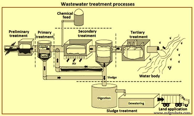
図1廃水処理プロセス
予備処理
前処理の目的は、閉塞、下流の機器の目詰まり、機器の摩耗を引き起こす可能性のある材料を除去することです。予備処理は通常、廃水がETPに送られる前に、ETPの性能を向上させるために行われます。この処理では、廃水から粗い固形物やその他の大きな物質が除去されます。これらの材料の除去は、後続の処理ユニットの運用および保守効率を高めるために不可欠です。この廃水の処理では、廃水の望ましくない特性を排除するために、いくつかのユニットプロセスが使用されます。これらには通常、(i)臭気の制御、および(ii)前曝気、粗い固体粉砕、スクリーンや火格子などを使用した大きな材料の除去などの操作が含まれます。多くの場合、油やグリース、およびpHの除去修正も行われます。
一次治療
これは、廃水処理プロセスの最初のステップ、または前処理後の2番目のステップです。一次処理は前処理に続き、アルカリ性条件から中和に近いpHにpHを補正するための物理的および化学的処理と、下流プロセスでのBODおよびSS負荷を低減するための一次浄化装置での浮遊物質の物理的沈降を含みます。全体として、一次浄化装置の採用は、下流の生物学的プロセス操作に関する問題が少ないことを表しています。たとえば、生物学的反応器での油脂とバイオマスの蓄積量が少なくなり、タンク内での沈下の可能性が最小限に抑えられ、活性汚泥バイオマスなどの「非フィラメント状」のバルキングの傾向が減少します。凝固–固形物の分離を改善するための凝集プロセス。
全体として、一次浄化装置の採用は、下流の生物学的プロセス操作に関する問題が少ないことを表しています。一次処理の目的は、沈降による沈殿性の有機および無機固形物の除去と、スキミングによる浮遊物質の除去です。一次処理では、通常、内向きBOD全体の約35%から55%、SS全体の約55%から75%、およびオイルとグリースの約70%が除去されます。一次沈降では、少量の有機リンと有機窒素、および固体に関連する重金属が除去されますが、コロイド成分と溶解成分は影響を受けません。
一次処理では、一次浄化装置を使用して、廃水から浮遊物質を物理的に分離します。この処理プロセスでは、TSSと関連するBODレベルが削減され、廃水処理の次のステップのために廃棄物が準備されます。この処理ステップの主な目的は、材料の沈降とスキミングによる沈殿可能な有機および無機固形物の除去です。
一次処理にはさまざまな物理化学的プロセスが含まれ、後続の処理プロセスの満足のいくパフォーマンスが保証されます。一次処理で使用される主なプロセスは沈降ですが、使用される補助プロセスは微細なスクリーニングと凝集および浮選です。凝集の前には、通常、石灰、ミョウバン、または独自の化学薬品による化学処理が行われます。この処理の主な目的は、沈殿によって金属を除去することと、関連するコロイド状BODを除去して化学スラッジを生成することです。一次処理では、凝固-凝集プロセスを適用して、固形物の分離を改善します。これらのプロセスのいくつかを以下に説明します。
凝集 –これは物理化学的プロセスであり、物理的に混合し、化学的凝固剤を補助することにより、粘性のあるコロイド状で繊細に分離された懸濁物質の凝集を促進します。このプロセスは、急速混合タンクと凝集タンクで構成されています。廃水流は急速混合タンクで凝固剤と混合し、次に凝集槽を通過し、凝集槽では廃棄物のゆっくりとした混合が起こり、粒子をより沈降性のあるより重い固形物の形で収集することができます。拡散した空気または機械的なパドルの助けを借りて、より良い混合が容易になります。天然有機ポリマー、無機電解質、および合成高分子電解質は、凝固に使用されるさまざまな種類の化学物質です。汚染物質の特性と化学的性質に応じて、特定の化学物質が選択されます。
沈降 –一次沈降の主な目的は、廃水中の固相画分と液相画分の分離を可能にすることです。重力を利用して、沈殿しやすい固形物を除去します。固形物は主に有機物であり、脂肪、油、グリースなどの浮遊物です。沈殿した固形物は一次スラッジとして知られています。したがって、このプロセスにより、流入する廃水のSS含有量が減少します。一次汚泥の量は流入排水量全体の約2%に過ぎませんが、受け取った有機物負荷(CODとして表される)の約30%から40%、SS負荷の約40%から60%を占めています。グリースと浮遊固形物を除去するためのバッフルとオイルスキマーは沈降チャンバーに含まれており、チャンバーの底からスラッジを除去するための機械式スクレーパーもあります。
固形物除去の効率は、沈殿槽または浄化装置の特性に依存します。沈降タンクは、エネルギーを散逸させるための入口バッフル、粒子状物質の沈降のための静止ゾーン、沈降した固形物を除去するための機械的手段、および出口への低流速を含む装置です。
凝集および沈降タンクは、長方形、円形、または傾斜プレート(Lamella)にすることができ、その選択は、現地の現場の状況、利用可能な面積、および設計チームの経験に基づいています。理想的には、2つ以上のタンクが必要です。長方形およびラメラタンクは、円形タンクよりも使用する土地面積が少なく、土地の利用可能性が少ない場合に役立ちます。
長方形のタンクは、凝集を増加させ(化学的に支援された沈降で)、保持時間を短縮するために、まっすぐな流れのパターンを持っています。水は一方の端から入り、入口バッフル装置を通過し、タンクの長さを横切って排水堰とトラフに到達します。それらは、長さ:幅の比率が3:1から5:1になるように設計されており、理想的な条件に非常によく似た大きな効果的な整定ゾーンと1%の底部勾配を提供します。下部の機械式スクレーパーが移動して、沈殿したスラッジを収集ゾーンに収集します。その後、スラッジはポンプで排出されます。
円形クラリファイア(図2)では、フローパターンは放射状です。放射状の流れのパターンを実現するために、排水はタンクの中央または場合によっては周辺の設計の大部分に導入されます。センターデザインでは、廃水は「センターウェル」と呼ばれるパイプと中央バッフルを通って運ばれ、タンクの周囲を走る堰に向かって放射状に流れます。中央の井戸の直径は、通常、タンク全体の直径の15%から25%で、高さは1mから2.5mです。静止沈降ゾーンは、離散的および凝集剤沈降のオーバーフロー率と深さの要件を満たすのに十分な大きさである必要があります。
処理水はVノッチ堰板から排出されます。床はスラッジの濃縮と除去を助けるために傾斜しています。スラッジは、メカニカルレーキを使用して除去されます。沈殿槽での一般的な滞留時間は2時間から3時間です。浮遊物質の除去は45%から55%です。
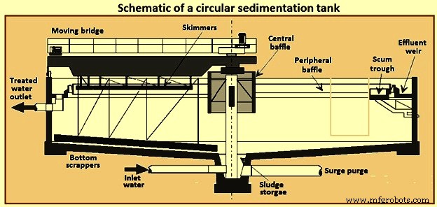
図2円形沈降タンクの概略図
溶存空気浮上 –このプロセスでは気泡が使用されます。それらは、廃水中の浮遊粒子を表面レベルまで上昇させて、浮遊粒子を容易に収集および除去できるようにするために必要です。廃水に導入された気泡は、主に粒子に付着して浮遊します。油性廃水およびその他の排水からの浮遊物質、分散油およびグリースは、溶存空気浮上(DAF)のプロセスによって除去できます。
油やグリースの除去には、特に浮遊物質の比重が1.0に近い場合に、溶存空気浮上法が適しています。 DAFプロセスでは、加圧空気を使用して、粒子に付着した微小気泡(直径10マイクロメートルから50マイクロメートル)を放出します。これにより、遊離油粒子が表面に浮き上がり、すくい取られやすくなります。 DAFプロセスは、油が自然に沈降せず、比重が水の比重よりも小さいため、油やグリースの除去に非常に効果的です。 When the oil is present in the emulsified form, it needs chemicals to destabilize the oil emulsion layer.
The pressurized water flow can be the entire inflow of wastewater, part of the inlet flow, or water already treated by the process (effluent). This results in dissolved air flotation to be three types of usable process, called full flow, partial flow or recirculated flow respectively. Fig 3 shows a schematic of the DAF process. The most common DAF application for wastewater treatment is a recirculated flow system, as it needs less equipment for pressurization (lower energy consumption), it avoids pump abrasion problems, and prevents the formation of colloids and emulsions within the pumping system.
DAF process can reduce oil concentrations to 10 mg/litre to 25 mg/litre as long as the influent concentration is not greater than 500 mg/litre. DAF process operates at higher hydraulic loading rates than gravity sedimentation systems and hence detention times are shorter by 15 minutes to 30 minutes. This allows the DAF process to be more compact and has a smaller footprint. DAF process systems are available in circular or rectangular configurations.
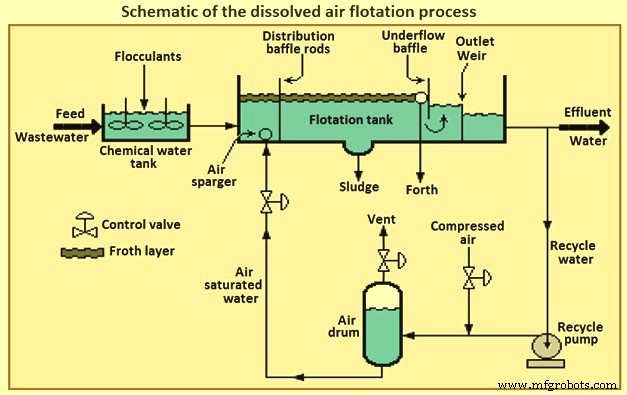
Fig 3 Schematic of the dissolved air flotation process
In retention tank the wastewater is pressurized and contacted with air. The super-saturated and pressurized water is passed through a pressure-reducing valve to the bottom of the floatation tank. The super-saturated air begins to come out in the form of fine bubbles from the solution, as and when the pressure starts releasing. The air bubbles attached with the suspended particles and trapped in sludge flock float over the surface and these floats are always swept from the surface and the mud is then collected from the bottom of the tank. The oil removal efficiency of the DAF process can be increased by the addition of certain coagulants.
Chemical treatment processes – The chemical treatment can be used, preferably before biological treatment as it removes the toxic chemicals which can kills the micro-organisms and or at any stage in the treatment process as and when it is necessary. Chemical treatment processes are described below.
Dissolved solids removal – Dissolved solids can be removed through a number of different methods namely (i) conversion to suspended materials, normally using chemicals to precipitate the contaminant as a solid or gas, to allow them to be removed by physical separation, (ii) adsorption onto a solid material, which can either be suspended or fixed as a bed, such as powdered or granular activated carbon, (iii) rejection using dense membrane processes, such as reverse osmosis or nano-filtration, or (iv) conversion to relatively innocuous end products.
Conversion necessarily involves chemistry or biochemistry, and the chemical reaction can be either reduction/oxidation (redox) or non-redox. Many chemical and biochemical processes operate by oxidation, the end products in the case of organic pollutants normally being carbon dioxide, nitrate and water. Examples of chemical reduction include the quenching of excess chlorine using bisulphite or the biochemical reduction of nitrate to nitrogen, the latter being referred to as ‘denitrification’. There also exist many important non-redox chemical processes, such as pH adjustment or precipitation of alkaline earth salts such as calcium carbonate or sulphate.
Neutralization – There is a wide range of pH of the untreated wastewater and it is not so easy to treat the wastewater with such type of varying range of the pH value. To optimize the treatment efficiency the neutralization process is used to adjust the pH value. To reduce the pH value sulphuric or hydrochloric acids can be added and to raise the pH value, dehydrated lime or sodium hydroxide alkalis can be added. Normally the process of neutralization is carried in a rapid mix holding tank or in a tank used for equalization. To control the pH of the discharge in order to meet the standards, the process of neutralization can be carried out at the end of the treatment.
Precipitation – The process of precipitation is carried out in two steps for the removal of the metal compounds from the stream of the wastewater. The mixing of precipitants with the wastewater and allowing a formation of the insoluble metal precipitants is the first step of the precipitation process. The removal of the precipitated metals from the wastewater through clarification and filtration is carried out in the second step and then the resulting sludge is being treated in a proper manner, and after treatment, it is recycled or disposed off. The important parameter to be considered in a chemical precipitation is pH controlling.
The solubility of metal hydroxides increases towards higher or lower pH and this is amphoteric in nature. Thus, for the precipitation of hydroxide for each metal, there is an optimum value of pH. As there is normally more than one metal in wastewater, hence, it is very much difficult to select the optimum treatment chemical and the pH control becomes more difficult and also it involves a transaction between the best possible removals of two or more metals. Lime, sodium hydroxide, soda ash, sodium sulphide and the ferrous sulphate are the various different chemicals used for the process of precipitation. The process for the effective removal of the metals like antimony, arsenic, chromium, copper, lead, nickel and zinc is normally the hydroxide precipitation and for removing mercury, lead, copper, silver, cadmium etc. sulphide precipitation is used. Fig 4 shows flow diagram of chemical treatment process for metal removal.
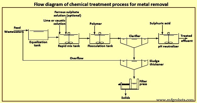
Fig 4 Flow diagram of chemical treatment process for metal removal
Secondary treatment
The secondary treatment process involves disintegration or decomposition of the suspended and dissolved organic substances present in the waste water using microorganisms. The activated sludge process (ASP) and the biological filtration methods are the mainly used biological treatment processes. The biological treatment process which is the mainly used for the secondary treatment process is based on the micro-biological action to decay the organic suspended and dissolved wastewater. The microbes can be used for the natural compound, both as a source of carbon sources and as an energy sources.
For removal of organic pollutants, the most efficient secondary treatment process is biological treatment. It primarily employs microbes naturally present in wastewater to break down organic contaminants. Some inorganic compounds like ammonia, cyanide, sulphide, sulphate and thio-cyanate are also biologically degradable. Biological processes can be broadly classified as (i) aerobic in which microbes which are used need oxygen to grow, (ii) anaerobic in which microbes which are used grow in the absence of oxygen but uses other compounds such as sulphate, phosphate or other organics present in the wastewater other than oxygen, and (iii) facultative in which microbes which are used can grow in the presence or absence of oxygen.
Aerobic processes consist of a biological reactor with a controlled amount of biomass and a clarifier for separation of the biomass from the final effluent. Aerobic processes need higher energy inputs and produce greater amounts of sludge compared to anaerobic systems. As an example, for the same 100 kg COD load entering the aerobic treatment plant, the energy needed is 100 kWh for aeration and produces 30 kg to 60 kg of sludge with the outlet effluent COD load of 2 kg to 10 kg. In the anaerobic treatment plant for the same 100 kg COD load, the sludge production is only 5 kg, or six to twelve times less, and produces 40 cum (cubic meter) to 45 cum of biogas which can be converted to produce 382 kWh of electricity. However, the outlet water COD is twice that of the aerobic plant, and hence of a lower quality.
Hydraulic retention time – It is the average time in the aeration basin equivalent to the volume of the basin divided by the average flow and expressed as hours. The hydraulic retention time is required to be sufficiently long to remove the prerequisite BOD and is dependent on the type of the biological treatment system. It can range from 0.5 hours to 120 hours. The lower the hydraulic retention time the quicker the wastewater reaches the outlet.
Mixed liquor suspended solids (MLSS) – Suspended solids level is one of the most important control parameters in biological wastewater treatment processes. It is not only directly related to sludge settling properties and effluent quality, but also related to food / micro-organism ratio which is in turn related with all aspects of sludge properties. MLSS represents the total suspended solids including bacteria, dead biomass, and higher life forms, irrespective of biological activity. The organic portion of MLSS is represented by ‘mixed liquor volatile suspended solids’ (MLVSS) which represents the biomass. MLSS is controlled by the sludge wasting rate. Typical MLSS are dependent on the process type. The more concentrated is the MLSS, the smaller is the equipment footprint and hence the popularity of membrane bioreactors (MBRs) in space constrained locations. MLVSS is 0.75 MLSS.
Food to microorganism (F/M) ratio – It is a term used for expressing the organic loading of an activated sludge process. F/M is a critical factor in process design and operation, especially in determining the aeration basin volume. F/M range is around 0.5 to 1.5. For conventional plants, F/M of 0.2 to 0.5 is aimed for. In biological treatment plants operating at high F/M loads (0.8 to 1.5), the rate of treatment increases at the cost of poor settlability of the sludge. Processes operating at low F/M loads (0.05 to 0.2) are associated with slow BOD removal rates but with good sludge settling. However, the system can be easily upset by a spike load of organics.
Sludge age – It is also known as ‘mean cell residence time’ (MCRT) and ‘solids retention time’ (SRT). It is calculated as the total quantity of sludge in the aeration tank and clarifier divided by the daily sludge losses through waste activated sludge and effluent. Sludge age can vary from 0.5 day to 75 days in low-growth rate systems. Sludge age is an indication of F/M ratios. Shorter times are indicative of high F/M ratios and longer times are indicative of low F/M ratios. Sludge age is expressed by the equation ‘sludge age =sludge mass in (aeration tank + clarifier) / daily sludge losses’.
The quality of sludge age can be determined using a microscope at 100x magnification. Daily microscopic analysis can prevent problems. Micro-organisms considered important in biological treatment are bacteria, fungi, algae, protozoa, rotifers, and worms. The presence of higher life form indicator organisms normally correlates to plant performance. They can indicate if the sludge is young, medium, or old. Good settling sludge is characterized by the presence of protozoa such as stalked ciliates and suctorians and normally is golden brown in colour (sewage treatment plants). Low sludge age is characterized by the absence of stalked ciliates and predominance of free swimming ciliates such as paramecium (these expend a lot of energy in swimming) and high BOD slugs by the absence of higher life forms. Old sludge is characterized by the presence of many worms (nematodes) or rotifers.
Another useful indicator is the ‘sludge volume index’ (SVI). Sludge is poured to a 1 litre graduated cylinder and the percentage of settled sludge in 5 minute intervals is noted for 30 minutes. SVI is expressed in ml/g. It is a reliable troubleshooting test. SVI values can vary from 30 ml/g to 400 ml/g. Values below 150 indicate good sludge settling and above this indicate sludge bulking. Other key variables which affect the operation of the biological reactor are given below.
Oxygen requirement – Oxygen is needed for the decomposition of organic matter. The concentration depends on organic matter consumption, endogenous respiration demand and total nitrification of TKN (total Kjeldahl nitrogen) oxidation. Typical oxygen concentration in an aeration tank is 2 mg/l to 4 mg/l. The higher values are maintained for nitrogen removal. Above this, electricity is wasted.
Sludge production (sludge yield) – The decay of biomass produces sludge. For conventional industrial systems, sludge production can be as low as 0.15 kg / kg BOD, such as in coke making.
Sludge recirculation rate – A portion of the sludge produced is recirculated to promote the production of more sludge in the aeration tank. It is the ratio between the sludge recirculation volumetric flow and treatment volumetric inflow. In any case, the capacity of the sludge recirculation system is not to be less than 200 % of the daily average total inflow.
Nutrient requirements (C:N:P ratio) – Besides carbon, hydrogen, and oxygen biomass needs nitrogen, phosphorous, and micro-nutrients such as iron, calcium, magnesium, copper, zinc and so on. Most industrial wastewaters lack N and P which is to be added (in the form of urea, super-phosphate or ammonium phosphate) to maintain optimal microbial growth conditions. The minimum C:N:P ratio needed for optimal microbial growth in the in aerobic processes is 100:5:1, and anaerobic processes is 330:5:1.
The most common biological processes are described briefly below.
Aerobic processes – activated sludge process – Biological processes, employing aerobic biomass in suspension, have traditionally been known as activated sludge processes. The ASP was developed in the United Kingdom in the early 1900s for the treatment of the domestic sewage and it has since been adapted for removing biodegradable organics in industrial wastewater. The ASP and its variants are capable of treating biodegradable wastewater of moderate strength (10 mg/l to 1,000 mg/l BOD) to high strength (greater than 1,000 mg/l BOD). The ASP does not remove heavy metals or TDS. Some contaminants such as cyanide, and heavy metals such as chromium and mercury, present in the wastewater act as inhibitors for the proper functioning of the ASP as well as other biological processes. ASPs have been categorized, according to the mass loading design, in three groups namely (i) low load activated sludge (extended aeration, oxidation ditches, etc.), (ii) medium load (or conventional), and (iii) high loading.
The ASP involves blending settled primary wastewater or equalized influent with a culture of micro-organisms into a fluid called ‘mixed liquor’. This mixed liquor is passed through an aeration tank which provides an adequate oxygen rich environment for the microbes to eat and stabilize the organic matter in water. Mixing brings oxygen and food to micro-organisms allowing the micro-organisms to clump together whilst preventing floc settling in the aeration tank. The process produces ‘waste activated sludge’ (WAS) consisting of microbes and excess microbial matter. The solids and treated wastewater are separated in a secondary clarifier or other solids separation step such as a membrane bioreactor (MBR). Here the majority of the WAS is returned to the aeration tank as returned activated sludge (RAS) to maintain the microbial population in the aeration tank, as well as ensuring that the activated sludge is old enough to degrade COD and aromatic hydrocarbons. The remainder is removed and undergoes thickening.
The secondary clarifier has the dual purpose of clarifying the wastewater as well as concentrating the sludge. The process is sensitive to pH fluctuations, where a high or low pH can upset the system and cause overloading of the clarifier. Fig 5 shows a schematic of the activated sludge process and membrane bioreactor process.
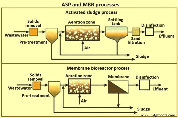
Fig 5 ASP and MBR processes
Nitrogen containing compounds are toxic to aquatic life, deplete oxygen in the receiving waters, adversely affect public health and reduce the potential for water reuse. Hence, nitrogen containing compounds are removed, if deemed excessive, by nitrification and then denitrification processes. Organic nitrogen is converted to ammonia, then converted to nitrite, which is further oxidized to nitrate and finally to gaseous nitrogen. Denitrification consumes alkalinity and needs to be sufficient so as not to depress the pH. It requires 7.14 mg/l of bicarbonate alkalinity for each 1 mg/l of ammonia nitrogen removed. Oxygen also needs to be maintained at concentrations closer to 4 mg/l for denitrification. The process control is normally customized for each effluent treatment system depending on wastewater characteristics and for optimal operation.
Aerobic processes – oxidation ditch process – This process which has been developed in the 1950s in the Netherlands, is a variant of the ASP and is a special form of extended aeration. The shape of the oxidation ditch is like a ring. Wastewater, micro-organisms and activated sludge is mixed in a continuous loop ditch in order to complete nitrification and denitrification reactions. The oxidation equipment consists of ditch body, aeration mixers and inlet and outlets. Given its long hydraulic retention time of 20 hours to 36 hours, low organic loading and long sludge age compared to conventional ASP, equalization, primary sedimentation, and sludge digestion tanks are omitted.
Oxidation ditch has many advantages in that it provides (i) low energy consumption, (ii) low maintenance, (iii) ease of operation, low capital expenditure, (iv) less sludge due to long extended solids retention time, and (v) resistance to shock loads and hydraulic surges due to long hydraulic retention time. The disadvantages are that the effluent suspended solid quality is inferior to the ASP process and needs a large land area.
Aerobic processes – sequencing batch reactor – The sequencing batch reactor (SBR) process differs from the other ASPs. It is a batch process. The principle is that all of the process steps of ASP, i.e. primary settling, biological oxidation and secondary settling take place in a single tank. The process steps are filling, react, settle, draw, and idle. SBR is compact and has low capital expenditure. It is used when land area is scarce since it needs only one tank to fulfill the aeration and clarification steps. It is also used to treat nitrogen and phosphorous. Standard cycles are normally 4 hour to 6 hours long, resulting in 4 to 6 reaction cycles per day. Compared to the conventional ASP, it is resistant to shock loading, flexible operation due to adjustment of run time and low sludge production.
Trickling filters – These filters, developed in the 1890s, are an example of a fixed film biological process compared to the ASP which is a suspended process. A trickling filter consists of bed of coarse material, such as rounded rocks (25 mm to 100 mm in diameter), crushed stone, wooden or plastic slats and plastic rings over which wastewater is discharged from moving spray distributors or fixed nozzles. The filter media provides a large amount of surface area for the micro-organisms to cling and grow a jelly like bio-film of around 10 mm thickness. In the outer portions of the bio-film (0.1 mm to 0.2 mm) the aerobic bacteria break down the organic matter. When the bio-film becomes very thick it falls off and a new bio-film layer forms. Modern trickling filters use plastic media over rocks since they weigh less and because of it, filter media can be upto 6 m in depth compared to 3 m in depth for rock filters, allowing taller filters using less land area.
The filter effluent is recycled to minimize drying of the filter media, improve filter efficiency, and reduce odour potential. Sometimes, two filters are assembled in series to handle strong wastewater. The sprays rotate at 2 revolutions per minute (rpm) to 5 rpm and a typical wetting rate is 0.6 cum/hour to 2.4 cum /hour. When the wetting rate is too low, the water does not penetrate the depth of the filter bed uniformly causing channeling and acts as an incubator for flies, as well as creating odour problems. Low rate filters operate on natural ventilation, whereas high rate filters require forced draft fans to provide adequate ventilation.
The trickling filter is followed by a secondary clarifier. Trickling filters are classified according to the organic and hydraulic loads such as low rate, intermediate, high rate, roughing filter and super high rate. The advantages of a trickling filter are (i) lower energy requirements than ASPs, (ii) simple operation with no issues of MLSS inventory control and sludge wasting, (iii) better recovery from shock toxic loads, (iv) no problems of bulking sludge in secondary clarifiers, (v) compact and suitable for place where land is scarce, (vi) less equipment maintenance needs, effective in treating high concentration of organics dependent on type of media used, and (vii) better sludge thickening properties. The disadvantages are organic loading levels, that the effluent water quality (in terms of BOD and TSS) is lower than ASP and can need further treatment, odour problems, flies, prone to plugging of filter media and at low temperatures natural ventilation systems do not operate that well.
Moving bed bioreactor – Moving bed bioreactor (MBBR) was developed in the 1980s by Kaldnes in Scandinavia. The MBBR process is a more modern fixed film process in which the micro-organisms grow on plastic media. The media are made from high density polyethylene or polypropylene with a diameter of 13 mm to 25 mm, and hence have a large surface area which helps the biomass to grow inside the surface and are in constant motion due to the compressed air which is blown from under the tank. The process has been applied in a variety of industrial wastewater treatment applications in aerobic and anaerobic modes with or without denitrification depending on the mode of mixing.
Benefits of MBBR are that it is good for high organic loading applications, improved settling characteristics, no need for sludge recirculation from secondary clarifier thereby making it a ‘once through’ process, compact and low footprint compared to the ASP process and has modular construction. It can also retrofit existing ASP systems, needs fewer operational controls than ASPs, and contains fewer mechanical and instrumentation controls compared to a MBR system. A typical hydraulic retention time for MBBR is 2 hours to 3 hours, compared to 12 hours to 24 hours for ASPs. Disadvantages of MBBRs compared to the ASP are that it needs a higher oxygen concentration, the need for improved influent wastewater screening, and additional hydraulic profile head losses due to flow through the media screening devices.
Membrane bioreactor – Though external membrane bioreactors were originally developed in the 1960s, they became popular only after the development of the immersed (submerged) MBRs in the late 1980s. The lower operating cost of the submerged MBR configuration and the decreasing cost of the membranes have made MBRs a popular choice for domestic and industrial wastewater treatment. MBRs are used for industrial wastes with BOD of 5,000 mg/l to 40,000 mg/l with BOD ranges of 200 mg/l to 600 mg/l. Fig 6 shows the principle of membrane bioreactor.
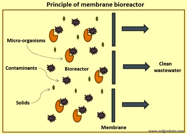
Fig 6 Principle of membrane bioreactor
The quality of the final effluent from a conventional ASP unit is highly dependent on the hydrodynamic conditions in the clarifier and settling characteristics of the sludge. This leads to variable performance. As a result, large clarifiers are needed with long residence times. The MBR process was developed to remove these disadvantages of conventional ASPs.
MBRs are a hybrid with two interdependent treatment processes:biological treatment and membrane treatment (Fig 5). It is similar to a conventional ASP in that both have mixed liquor solids in suspension in an aeration tank. The difference in the two processes lies in the method of separation of bio-solids. In the MBR process, the membranes create a solid barrier to bio-solids based on micro-filtration (MF) with a pore size of 0.6 micrometers, or ultra-filtration with a pore size of 0. 04 micrometers, and hence are not subject to gravity settling characteristics of the solids. Thus, a MBR unit brings aeration, clarification, and filtration in a single step with MLSS concentrations reaching 20,000 mg/l or higher resulting in a smaller footprint than conventional ASP units.
MBRs provide a final effluent quality independent of sludge conditions with higher removal of organics and persistent pollutants, and nutrients with COD removal of 98 % and suspended solids removal efficiency of 100 %. The high quality effluent produced is ideal for reuse applications. Another feature of MBRs is the long sludge age. However, this also contributes to fouling of membranes. Moreover, MBR units can be installed directly to a reverse osmosis (RO) plant, bypassing the need for an ion exchange or other equipment to protect a membrane plant provided the hardness or scaling compounds are not excessive.
There are two types of MBR configurations namely immersed and side-stream. Immersed systems are more common in large industrial units, whereas side-stream is limited to smaller units. There are also differences in the membrane employed from hollow fibre, flat plate, and tubular. Immersed MBRs use hollow fibre or flat plate whereas tubular membranes are used in side-stream MBRs. MBR produces an equivalent treatment level to an activated sludge process followed by micro-filtration or ultra-filtration.
Despite the advantages of MBRs, there are still challenges in using MBRs in industrial applications. The advantages of MBR are (i) 25 % lower footprint, (ii) replaces the clarifier and gravity filter of conventional systems, (iii) ideal for land constrained sites and lower hydraulic retention time of 4 hours to 8 hours. MBR provides impermeable barrier for solids producing highest quality effluent with BOD less than 5 mg/l and turbidity of less than 0.1 NTU (Nephelometric turbidity unit). Membrane fouling is one of the major challenges which results in reduced performance and frequent cleaning or membrane replacement leading to increased maintenance and operating costs. All MBRs require a minimum of fine screens of 3 mm. Sludge produced can be difficult to dewater. Sludge retention time is independent of hydraulic retention time. High sludge age of 15 days to 140 days can be obtained. It has modular expandability, less odour, and flexible operation with less susceptible to upsets. The process can be automated.
Secondary clarifiers – The purpose of the clarifier is twofold. One is to thicken the solids after biological treatment and then settle them out. The second is to produce a clear effluent of the settled solids. Clarifiers in activated sludge systems are to be designed not only for hydraulic overflow rates, but also for solids loading rates. This is because both clarification and thickening are needed in activated sludge clarifiers. Of the process variables the most important is sludge age or mean cell residence time. Another important control parameter is the solids loading rate which is defined as the required surface for suitable sludge thickening in the bottom of the unit (compression zone). The clarifiers are either of rectangular design or of circular design.
Tertiary treatment
Conventional secondary treatment frequently is not sufficient to meet the required effluent quality standards to discharge water to surface water bodies. The effluents can need tertiary processes so as to complete solids and organic matter removal, for colour reduction or recalcitrant compounds degradation, nutrient reduction, and disinfection. The persistent contaminants which the secondary treatment is not able to remove are removed by the tertiary treatment process. These processes are classified as ‘tertiary treatments’, as they are installed after secondary treatment, but some of them, like oxidation processes, can be also placed before biological treatment to improve the bio-degradability of recalcitrant compounds.
Before the treated wastewater is reused, recycled, or discharged to the environment, the tertiary treatment process is used as a final cleaning process cleaning process to improve the quality of the wastewater. For the removal of nutrient (nitrogen and phosphorus), removal of toxin [pesticides, VOC &metals], and for the polishing of the effluent like BOD &TSS, the tertiary treatment processes are used. These processes are the extension of conventional secondary biological treatment process for the further stabilization of the substances which demands oxygen in the wastewater, and also to remove the nitrogen and phosphorus.
The physical and chemical separation techniques like activated carbon adsorption, flocculation or precipitation are the process involved in the tertiary treatments. The most common tertiary treatment applications are filtration and disinfection and where applicable ammonia and phosphorous removal. Ammonia is toxic to fish and phosphorous causes algal blooms.
Filtration – Filtration is a separation process which consists in passing a solid–liquid mixture through a porous material (filter media) which retains the solids and allows the liquid filtrate to pass through. Granular media polishing filters are used the removal of suspended solids for the removal of suspended solids in the 5 mg/l to 50 mg/L range. The most common filters are the multimedia filters. The quality of the filtrate depends on the size, surface charge, and geometry of both suspended solids and filter media, as well as on the water analysis and operational parameters. Based on media filters can be categorized as (i) single media (sand or anthracite), (ii) dual media (sand and anthracite), and (iii) multimedia (garnet, sand, and anthracite).
The most common filter media in water treatment are sand and anthracite. The effective grain size for fine sand filter is in the range of 0.35 mm to 0.5 mm, and 0.7 mm to 0.8 mm for anthracite filter. In comparison to single sand filter media, dual filter media with anthracite over sand permit more penetration of the suspended matter into the filter bed, thus resulting in more efficient filtration and longer runs between cleaning. The design depth of the filter media is a minimum of 0.8 m. In the dual filter media, the filters are normally filled with 0.5 m of sand covered with 0.3 m of anthracite.
In industrial applications, filters are housed in steel pressure vessels where the interior is epoxy coated, with interior manifolds for distribution of water and an under drain system for collection of filtrate and backwashing.
As the filter vessel for pressure filtration is designed for pressurization, a higher-pressure drop can be applied for higher filter beds and / or smaller filter grains and / or higher filtration velocities. The design filtration flow rates are normally 10 m/h to 20 m/h and the backwash rates are in the range of 40 m/h to 50 m/h. The available pressure is normally about 2 bars to more than 4 bars.
For feed waters with a high fouling potential, flow rates of less than 10 m/h and / or second pass media filtration are preferred. If the flow rate has to be increased to compensate for one filter which goes out of service, the flow rate increase is to be gradual and slow to prevent the release of previously deposited particles.
During operation, influent water to be filtered enters at the top of the filter, percolates through the filter bed, and is drawn off through the collector system at the bottom. Periodically, when the differential pressure increase between the inlet and outlet of the pressure filter is 0.3 bars to 0.6 bars, the filter is backwashed and rinsed to carry away the deposited matter. Backwash time is normally about 10 minutes. Before a backwashed filter is placed back into service, it is to be rinsed to drain until the filtrate meets the specification. Backwash rates when excessive leads to loss of filter media.
Variations of the deep rate filtration are high rate filtration which operates at much faster inlet flow rates. Aside from media filters, other types of filters are disc filters and cartridge filters. These are also used to protect membrane filtration systems. Disc filters made from pleated cloth media have very high flow rates and a small footprint, producing very high quality water suitable for reuse applications and do not need extensive backwashing.
Some advanced water treatment processes are also used as the tertiary treatment. These processes are applied to the conventional treated wastewater to improve the quality upto a degree suitable for various applications of recycle and reuse including the potable reuse. The additional tertiary treatment processes are different membrane treatment processes like micro-filtration, ultra filtration, nano-filtration, other processes like reverse osmosis, advanced oxidation processes, and additional disinfection processes like ozonation and the use of ultraviolet radiation. Some of these advanced processes are described below.
Membrane technology – Membranes are a popular choice for water reuse applications since their advent in the 1960s. Costs of membrane systems have reduced dramatically and, coupled with technological advances in membrane design, membrane options and operating limits, the range of applications in water and wastewater treatment is increasing rapidly. In pressure driven membrane filtration, membranes separate the components of a fluid under pressure. The membrane pores, being extremely small, allow the selective passage of solutes. The popularity of membrane processes arises from the fact that they are effective in the removal of both dissolved and suspended solids. A wide range of materials like cellulose acetate, polyamides, poly- sulfones, poly-propylene, nylon, poly-acrylonitrile, poly-carbonate, polyvinyl alcohol, poly-tetra-fluoro-ethylene, ceramic, and metal composites are basically used to produce the membranes. The membrane pore size is the parameter for the degree of selectivity of a membrane. On the basis of the pore size, there are four types of pressure driven membranes. Micro-filtration and ultra-filtration are low pressure applications given their larger pore size. Nano-filtration needs medium pressure, and ‘reverse osmosis, given the smaller pore size, needs significant pressure to push the solute through the membrane.
Advanced oxidation processes – Advanced oxidation processes (AOPs) are defined as processes which involve generation and use of powerful but relatively non-selective hydroxyl radicals in sufficient quantities to be able to oxidize the majority of the complex chemicals present in the effluent water. The AOPs show specific advantages over conventional treatment alternatives since they can eliminate non-biodegradable organic components and avoid the need to dispose of residual sludge. After fluorine ([V (volts) =-3.06], hydroxyl free radicals (OH-) have the highest oxidation potential (V =-2.86). In the AOP process, OH – radicals are generated which in turn react with organic molecules to generate CO2 and water. AOPs can be classified into two groups, non-photochemical AOPs and photochemical AOPs. Photochemical means a light source is needed. Normally ultra violet (UV) light is used as the photo-chemical source. Low pressure UV lamps have a wavelength of 254 nm. Maximum ozone absorption takes place at a wavelength of 253.7 nm. Of the non-photo-chemical technologies, those most prevalent in the treatment are Ozonation, Ozone/ (H2O2) and Fenton’s reaction.
Ozonation – Discovered in 1785, Ozone (O3) is a widely applied strong oxidizing agent (-2.07V) for disinfection of potable water and wastewater, decolourization, odour removal, organics degradation and cyanide destruction, etc. O3 at room temperature is a bluish pungent gas, sparingly soluble in water, highly corrosive, toxic and explosive when the concentrations in air exceed 20 %. As a germicide, it is 3,125 times faster than chlorine. Ozonation efficacy is increased with high pH and temperature. When O3 dissolves in water or wastewater it can remain as the O3 molecule (at pH more than 7 and slower reaction) or decompose (pH more than 8) producing the hydroxyl free radical (OH-) which is a 35 % stronger oxidizing agent than O3. Both reactions occur simultaneously and hence reaction kinetics strongly depends on the characteristics of the treated wastewater (e.g. pH, organic concentrations, presence of foaming agents and surfactants, ozone concentration and temperature, etc.). A pH of 8 to 10 is most suitable for oxidation of organic compounds. Ozone is sparingly soluble in water and rapidly decreases with increasing temperature. At a temperature of 20 deg C, 100 % ozone solubility in water is 570 mg/l. The preferred temperature ranges from 25 deg C to 50 deg C.
A simplified reaction mechanism of ozone at a high pH is given by the equation 3 O3 + H2O =2OH radical + 4 O2. Molecular O3 is a very selective oxidant. It only reacts with certain compounds and for this reason it can be applied in low dosages for industrial wastewater applications. It can also inhibit or destroy the foaming properties of residual surfactants as well as oxidizing a good portion of the COD. Thus, O3 improves the overall biodegradability of the effluent by converting recalcitrant compounds to easily digestible compounds and can be applied upstream or downstream of a biological treatment plant. The residual oxygen in the vent gas can be recycled back to the secondary biological treatment plant, reducing aeration requirements. Another advantage is that it does not increase sludge mass.
O3 can be applied in the gaseous form and because of its unstable nature it needs to be generated on-site from air or pure oxygen using UV radiation, electrochemistry or corona discharge generators. O3 leak detectors are to be installed to give audible and visible warnings and shut down the generators in the event of a leak. O3 is deactivated in the presence of high concentration of salts. A variation of this process is the O3/H2O2 process. Developed to reduce the O3 concentrations, the H2O2 acts as a catalyst enhancing the capability of O3 to produce more OH radicals. At a low pH, H2O2 reacts very slowly with O3 and at a high pH (alkaline conditions) reacts rapidly.
製造プロセス