


光学顕微鏡
光学顕微鏡
顕微鏡検査は、肉眼で適切に見るには小さすぎる物体の画像の拡大を研究します。顕微鏡検査は、観察されるサンプルによって放出、吸収、透過、または反射された放射線(図1)を利用することによってその役割を果たします。放射線の性質は、光学顕微鏡、電子顕微鏡、X線顕微鏡、音響顕微鏡などの顕微鏡の種類を指定します。電磁スペクトルの可視部分は、光学顕微鏡で使用される放射線の種類です。光学顕微鏡は、光学顕微鏡による材料の顕微鏡検査です。
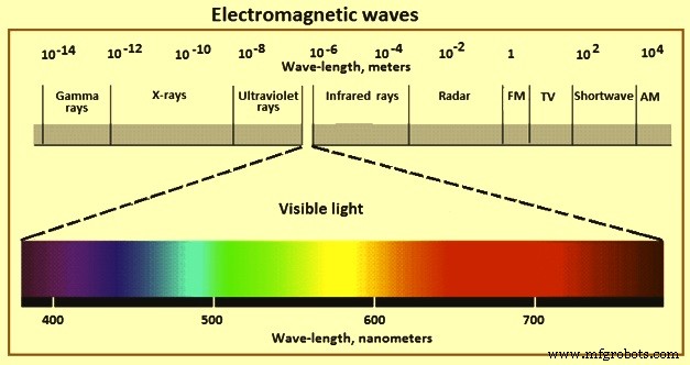
図1電磁波
古くは大まかな拡大鏡が使われていましたが、現代の顕微鏡の進化は17世紀に始まりました。最初の複合顕微鏡は1595年にハンスとサハリアスヤンセンによって製造されましたが、アントニファンレーウェンフック(1632–1723)は、非常に単純な顕微鏡で約300倍の驚くべき倍率を達成するためにレンズを非常に優れたものにすることができました。 1670年頃の科学者ロバートフックの提案により、ロンドンの楽器製作者クリストファーコックは非常に成功した複合顕微鏡を構築しました。この機器で、フックは細胞を観察することができました。フックの顕微鏡は、現代の楽器の父と見なすことができます。
光学顕微鏡は、しばしば「光学顕微鏡」と呼ばれ、可視光(図1)とレンズのシステムを使用して小さなサンプルの画像を拡大するタイプの顕微鏡です。光学顕微鏡は、最も古く、最も単純な顕微鏡です。洗練された電子金属組織学的機器の進化にもかかわらず、それは微細構造の研究にとって非常に重要な機器です。洗練された「走査型電子顕微鏡」(SEM)と「透過型電子顕微鏡」(TEM)も非常に貴重な機器です。ただし、代替品としてではなく、光学顕微鏡と組み合わせて使用する必要があります。
微細構造のすべての検査は、光学顕微鏡の使用から始まり、100倍などの低倍率で開始し、その後、微細構造の基本的な特性を効率的に評価するために徐々に倍率を上げていきます。微細構造の大部分は光学顕微鏡で観察でき、その特性に基づいて識別できます。疑わしいまたは未知の成分の識別は、マトリックスに対するそれらの硬度の観察、それらの自然な色、偏光に対するそれらの応答、および選択的エッチャントに対するそれらの応答によって助けることができる。これらの観察結果は、調査対象の材料の物理的冶金に関する既知の詳細と比較されます。それでも疑問が残る場合、または構造が細かすぎて観察できない場合は、より高度な手法を実装する必要があります。
光学顕微鏡は、研磨されたままの、またはエッチングされた金属組織学的サンプルを検査するために使用することができます。特定の成分は、エッチングの詳細によって隠されていないため、研磨されたままの状態でより簡単に観察できます。介在物、窒化物、特定の炭化物、および金属間化合物相は、エッチングなしで容易に観察できます。介在物を除いて、最終研磨中にいくらかのレリーフが導入されれば、他の相をより簡単に調べることができます。サンプルは、アーチファクトによる合併症なしに微細構造の正しい観察と解釈を確実にするために適切に準備されるべきです。非立方晶構造の材料など、偏光に反応するサンプルは、通常、エッチングなしで検査されます。ただし、ほとんどの場合、微細構造を観察するためにエッチングを行う必要があります。汎用エッチャントは通常、最初に粒子構造と存在する相を明らかにするために使用され、次に対象の特定の相を攻撃または着色する選択的エッチャントが続きます。選択的エッチャントは、特に自動化されたデバイスを使用して実行される場合、定量的金属組織学に広く使用されています。いずれの場合も、エッチングを慎重に実行して、微細構造を明確に明らかにする必要があります。
顕微鏡は、非常に短い焦点距離の対物レンズを使用して、非常に拡大された画像を形成します。この画像は、単純な拡大鏡として使用される短い焦点距離の接眼レンズで表示されます。光学顕微鏡の基本的なイメージングの概念と構造を図2に示します。顕微鏡の光学システムには、主に対物レンズと接眼レンズが含まれています。対物レンズの目的は、ユーザーがはっきりと観察できるように物体を拡大することです。観察中、サンプルは物体空間内の対物レンズの焦点面の近くに配置され、サンプルの拡大された実像が最初に中間面に作成されます。中間面は接眼レンズの焦点面に配置されているため、接眼レンズは拡大鏡として機能し、中間像面に投影された画像をさらに拡大します。最後に、拡大された仮想の反転画像が観察者に提供されます。
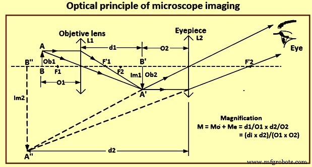
図2顕微鏡イメージングの光学原理
物体上のさまざまな点の分離可能な画像を生成する光学顕微鏡の能力は制限されています。レンズの解像力は、この能力の定量的尺度です。解像度の限界より近いポイントは、個別のポイントとして区別できません。 1873年にエルンストアッベは最初に2つの隣接する点の間の最小距離dの値を修正し、方程式「d =l / 2n sin A」によって分離されていると認識できるようにしました。ここで、「l」は光の波長「A」です。はレンズの開口角の半分であり、「n」は物体とレンズの間の媒体の屈折率です。
現在、対物レンズで解像できる2つの物体点の最小線形分離は、方程式「d =1.22(l / 2NA)」で与えられるレイリー基準によって固定されています。ここで、「l」は光の波長であり、 「NA」は、対物レンズの開口数です。アッベ基準とレイリー基準はどちらも非常に似ており、NA =n sin Aによってイメージング媒体に関連する開口数です。sinAの最大値は1(A =90度)であるため、理論上の最大開口数は空気中の対物レンズ(n =1)はNA =1です。高NAは高解像度に不可欠な要件であるため、液浸光学系が開発されました。サンプルは、水(n =1.33)、グリセリン(n =1.47)、または油(n =1.52)などの異なる屈折率を持つ液浸媒体を介して対物レンズから非常に短い距離で画像化できます。
適切に設計された顕微鏡の場合、空間分解能は主に対物レンズによって決定されます。接眼レンズでも画像を拡大することはできますが、顕微鏡の解像力を向上させることはできません。光学顕微鏡の空間分解能は、レイリー方程式Ro =0で与えられます。 62 l / n sin A、ここで、「Ro」は最小分解可能距離、「l」は光の波長、「n」はレンズと物体の間の媒体の屈折率、「A」は1です。 -レンズの開口数の半分。nsinAは対物レンズの開口数です。
上記の式に基づいて、実際の制限、すなわち(i)390 nm(ナノメートル)から760 nmの波長の可視光の使用を考慮すると、(ii)70度から75度の半角で最大到達可能な開口部度、および(iii)屈折率を上げるために水または油に浸漬する方法を使用する必要がある場合、従来の光学顕微鏡の解像度は200nmを超えることはできません。
光学顕微鏡と顕微鏡の簡略化された光波経路を図3に示します。最新の光学顕微鏡は、空間分解能の制限が200 nmで、物体を1,500倍に拡大することができます。光学顕微鏡は、さまざまな基準を使用して多くの異なるタイプに分類できます。たとえば、照明方法に基づいて、顕微鏡の透過型と反射型があります。透過型顕微鏡では、光は透明な物体を通過します。反射顕微鏡では、顕微鏡レンズの上部に設置された光源が不透明な物体を照らし、反射光がレンズによって集められます。顕微鏡は、明視野顕微鏡、暗視野顕微鏡、位相差顕微鏡、偏光顕微鏡、干渉顕微鏡、蛍光顕微鏡などの観察方法に基づいて区別することもできます。
各顕微鏡は、透過アプローチまたは反射アプローチのいずれかを使用できます。明視野顕微鏡は、すべての顕微鏡の中で最も人気があり、広く使用されています。このタイプの顕微鏡を使用すると、一部の観察対象物の透過(または吸収)比と反射率は、作業環境の変化に応じて変化します。これらのオブジェクトの振幅は、照明強度の変化に応じて変化します。無色透明のオブジェクトは、照らされた光の位相が変化したときにのみ表示されます。明視野顕微鏡は光の位相を変えることができないため、このタイプの顕微鏡を使用すると、無色透明のサンプルは見えなくなります。
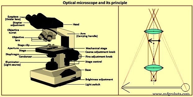
図3光学顕微鏡とその原理
顕微鏡コンポーネント
光学顕微鏡は、コストと機能が大幅に異なります。反射光は金属の研究に使用されます。透過型光学顕微鏡は、鉱物やポリマーの研究に使用されます。これらは、反射光を使用して調べることもできます。光学顕微鏡も「直立」または「倒立」に分類されます。これらの用語は、観察中のサンプルの研磨面の向きを指します。各構成には特定の長所と短所があるため、選択は個人の好みに基づいて行われます。最も単純な光学顕微鏡はベンチタイプ(通常は直立)です。スタンドの剛性に応じて、一部の顕微鏡に写真機能を追加できます。
観察および写真顕微鏡に適したさまざまなタイプの顕微鏡が利用可能です。これらは、さまざまな照明モード、光源、微小硬度アタッチメント、ホットステージなどを備えた、かなり単純なユニットまたは実物大の研究用顕微鏡にすることができます。光学顕微鏡の基本的なコンポーネントを以下に示し、図3に示します。
イルミネーション システム –光学顕微鏡用のさまざまな光源が利用可能です。主にベンチ顕微鏡で使用される低電圧タングステンフィラメントランプは、観察には十分な強度がありますが、写真には十分な強度がありません。電球への電流を変えると、光の強さが制御されます。かつて顕微鏡で一般的だったカーボンアーク照明システムは、アークまたはフィラメント光源に置き換えられました。キセノンアーク光源は、その高強度と昼光色特性のために普及しています。ただし、光の強度は、減光フィルターを使用することによってのみ調整できます。タングステンハロゲンフィラメントランプは、高強度と高色温度のために広く使用されています。光の強さは、電流を変えるか、減光フィルターを使用して制御できます。ジルコニウムアーク、ナトリウムアーク、石英ヨウ素、水銀灯などの他の光源はあまり一般的ではありません。
コンデンサー –球面収差とコマ収差のない調整可能なレンズを光源の前に配置して、光路の目的のポイントに光を集束させます。顕微鏡内の内部グレアと反射を最小限に抑えるために、フィールド絞りがこのレンズの前に配置されています。フィールド絞りは、視野の端まで停止します。 2番目の調整可能な虹彩絞りである開口絞りは、垂直照明器の前の光路に配置されます。
この絞りを開閉すると、対物レンズに入る光の量と光錐の角度が変わります。この絞りの最適な設定は、対物レンズごとに異なり、画像のコントラスト、シャープネス、被写界深度の間の妥協点です。倍率が上がると、絞り絞りが絞り込まれます。この絞りを開くと、画像の鮮明さが増しますが、コントラストは低下します。絞りを閉じるとコントラストは上がりますが、画像の鮮明さが損なわれます。絞り絞りは、光の強度を下げるために使用することはできません。コントラストとシャープネスのみを調整します。
ライトフィルター –これらは、観察を容易にするため、写真顕微鏡を改善するため、またはコントラストを変更するために光を変更するために使用されます。ニュートラルデンシティフィルターは、可視スペクトル全体で光強度を均一に低減するために使用されます。透過率が約85%から0.01%のさまざまな減光フィルターを利用できます。光学顕微鏡の大部分には、少なくとも2つのそのようなフィルターが選択されています。
選択フィルターは、光源の色温度とフィルムの色温度のバランスをとるために使用されます。これは、使用する光源やフィルムの種類によっては、カラー画像を忠実に再現するために必要になることがよくあります。緑または黄緑のフィルターは、白黒写真で広く使用されており、レンズの欠陥が画質に与える影響を軽減します。目的の大部分、特に低コストのアクロマートは、良好な結果を得るためにそのようなフィルタリングを必要とします。
偏光フィルターは、非立方体(結晶学的)材料の検査のために、平面偏光(1つのフィルター)または交差偏光(2つのフィルターを回転させて消光)を生成するために使用されます。ベリリウム、ジルコニウム、アルファチタン、ウランなどの光学的に異方性のある材料は、エッチングなしで交差分極状態で検査できます。敏感な色合いのプレートは、交差偏光と一緒に使用して、着色を強化することもできます。
対物レンズ –それは微細構造の主要な画像を形成し、光学顕微鏡の最も重要なコンポーネントです。対物レンズはサンプルからできるだけ多くの光を集め、この光を組み合わせて画像を生成します。対物レンズのNAは、レンズの集光能力の尺度です。集光能力は角度「A」で増加します。絞り絞りの設定により、コンデンサーのNAが変更され、システムのNAが変更されます。
対物レンズ(図4)は通常、4〜6個の対物レンズを受け入れることができるノーズピースタレットに取り付けられます。一部の顕微鏡はノーズピースタレットを使用せず、バヨネットマウントを使用して垂直イルミネーターに一度に配置できる対物レンズは1つだけです。垂直イルミネーターには、光を対物レンズからサンプル表面に向けて偏向させるリフレクターまたはプリズムが含まれています。通常、絞りとフィールドダイアフラムおよびフィルターも保持します。垂直照明器は通常、明視野照明と暗視野照明、または明視野照明と偏光照明など、1つまたは2つのタイプの照明のみを提供します。ただし、1つの垂直照明と1セットの対物レンズですべてのタイプの照明を提供するユニバーサル垂直照明が利用可能になりました。
チューブの長さは、接眼レンズのアイラインから対物レンズまでのボディチューブの長さです。この長さは標準化されておらず、変更される可能性があります。対物レンズの大部分は、特定のチューブ長(通常は160mmから250mm)で使用するように設計されており、通常は交換できません。
最も一般的に使用される対物レンズはアクロマートです。これは、1つの色(通常は黄緑色)と2つの色(通常は赤と緑)の縦色収差を球面補正します。したがって、アクロマートはカラー写真顕微鏡には適していません。黄緑色フィルターとオルソクロマチックフィルムを使用すると、最適な結果が得られます。ただし、アクロマートは比較的長い作動距離、つまり対物レンズのフロントレンズからサンプル表面までの距離を提供します。対物レンズの倍率が上がると、作動距離は短くなります。生産者の大多数は、例えば、ホットステージ顕微鏡法などの特別な用途のために、長時間作動距離の対物レンズを製造しています。アクロマートには歪みがなく、偏光検査に重要です。他のより高度に補正されたレンズよりもレンズが少ないため、内部反射損失が最小限に抑えられます。
セミアポクロマートまたは蛍石の対物レンズは、球面収差と色収差をより高度に補正します。したがって、アクロマートよりも高品質の画像を生成します。アポクロマート対物レンズは、最高の補正度を持ち、最良の結果を生成し、より高価です。プラノ対物レンズは、眼精疲労を軽減する視野の平坦性を大幅に補正しており、最新の顕微鏡でよく見られます。
パーフォーカルレンズシステムでは、タレットを回転させたときにノーズピースタレットの各対物レンズにほぼ焦点が合っているため、レンズを切り替えたときに対物レンズのフロントレンズがサンプルに当たるのを防ぎます。多くの対物レンズにもバネ仕掛けがあり、レンズの損傷を防ぐのに役立ちます。作動距離が非常に短くなる可能性があるため、これは高倍率の対物レンズではさらに問題になります。
特定の対物レンズは、サンプルと対物レンズのフロントレンズの間のオイルで使用するように設計されています。ただし、サンプルとレンズは使用後に洗浄するため、油浸レンズはほとんど使用されません。ただし、レンズとサンプルの間に空気がある場合よりも高い解像度が得られます。後者の場合、可能な最大NAは0.95ですが、油浸レンズは1.3NAから1.45NA 、を生成します。 レンズと使用するオイルによって異なります。 25倍から160倍までの倍率が利用可能です。石油を使用すると画像も鮮明になります。これは、石炭やセラミックなどの低反射率の標本を調べるときに役立ちます。
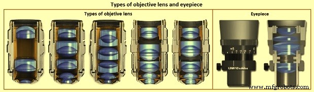
図4対物レンズと接眼レンズの種類
接眼レンズ –接眼レンズとも呼ばれます。接眼レンズ(図4)は、対物レンズによって生成された一次画像を拡大します。その後、目は対物レンズのフル解像度機能を使用できます。顕微鏡は、通常は目から250 mmの位置にある、最も明確な視界のポイントでサンプルの虚像を生成します。接眼レンズはこの画像を拡大し、有用な倍率を達成できるようにします。標準の接眼レンズの視野は直径24mmですが、平面目的の広視野接眼レンズの視野は直径30 mmであるため、プライマリ画像の使用可能領域が広がります。
最も単純な接眼レンズは、C。ホイヘンスによって設計が発明されたホイヘンの接眼レンズです。これは、凸面が対物レンズに面している2つの平凸レンズで構成されています。低出力および中出力のアクロマート対物レンズでの使用には十分です。補正接眼レンズは、高NAアクロマートとより高度に補正された対物レンズで使用されます。一部のレンズ補正はこれらの接眼レンズを使用して実行されるため、接眼レンズは使用する対物レンズのタイプと一致させる必要があります。
アイクリアランスは、接眼レンズの目のレンズと目の間の距離です。ほとんどの接眼レンズでは、アイクリアランスは10 mm以下であり、顕微鏡を使用する人が眼鏡をかけている場合は不十分です。近視などの単純な視力の問題は、微調整を使用して対処できます。乱視などの視力障害は顕微鏡では矯正できず、眼鏡をかける必要があります。眼鏡に必要な約20mmのアイクリアランスを提供するハイアイポイント接眼レンズが利用可能です。
接眼レンズには通常、微細構造の位置を特定、測定、カウント、または比較するためのさまざまなレチクルまたは経緯線が装備されています。接眼レンズは、レチクルまたは経緯線の画像と一次画像を拡大します。両方の画像に同時に焦点を合わせます。特別な接眼レンズも製造されており、経緯線スケールで行うよりも正確な測定が可能です。例としては、フィラメントマイクロメートルの接眼レンズまたはスクリューマイクロメートルの接眼レンズがあります。このようなデバイスを自動化して、測定値を直接デジタルで読み取ることができます。これは、約1マイクロメートルの精度です。
通常、10倍の倍率の接眼レンズが使用されますが、標準の倍率を得るには、6.3倍などの他の倍率が必要なシステムもあります。 1倍、15倍、20倍、25倍などの高倍率の接眼レンズも、特定の状況で役立ちます。全体の倍率は、対物レンズの倍率Moに接眼レンズの倍率Meを掛けることで求められます(図2)。ズームシステムまたはベローズも使用されている場合は、それに応じて倍率を変更する必要があります。
ステージ –サンプルの焦点を合わせて移動するための機械式ステージが用意されており、ステージ上に配置され、クリップを使用して固定されます。倒立顕微鏡のステージには、さまざまなサイズの穴が付いた交換可能なセンターステージプレートがあります。研磨された表面は、表示用の穴に配置されます。ただし、表面全体を見ることができず、高倍率では、作動距離が制限されているため、穴の端の近くに対物レンズの焦点を合わせることができません。直立顕微鏡の場合、サンプルはステージ上のスライドに配置されます。研磨面は光線に対して垂直であるため、サンプルの底とスライドの間に粘土を配置します。レンズティッシュを研磨面に置き、レベリングプレスを使用してサンプルを粘土に押し込みます。ただし、組織片がサンプル表面に付着する可能性があります。マウントされたサンプルで特に役立つ代替手段は、組織の代わりにリングを使用してサンプルを平らにすることです。サンプルではなく、マウントのマウント(万力でわずかに平らになっている)シートと同じサイズのアルミニウムまたはステンレス鋼のリングフォーム。
直立顕微鏡により、任意の対物レンズで表面全体を見ることができ、オペレーターはサンプルのどの部分が見られているかを見ることができます。これは、コーティングされたサンプル、溶接、および特定の領域を検査するその他のサンプルの特定の領域を検査する場合に便利な機能です。マウントされたサンプルの場合、マウント用の自動レベリングステージホルダーを使用すると、粘土上のサンプルのレベリングをなくすことができます。
ステージは振動をなくすために剛性があります。 xマイクロメートルとyマイクロメートルで制御されるステージの動きは、スムーズで正確である必要があるため、通常はラックアンドピニオンギアが使用されます。多くのステージには、x方向とy方向の距離を測定するための目盛りがあります。フォーカシングコントロールには、垂直方向の動きを推定するためのルールが含まれていることがよくあります。一部のユニットには、電動ステージとフォーカスコントロールがあります。
円形の回転可能なステージプレートは、偏光検査を容易にすることができます。鉱物学または岩石学の研究に一般的なこのような段階は、回転角の測定を可能にするために段階的に行われます。直線ステージは通常、円形ステージの上に配置されます。
スタンド –ベンチ顕微鏡は、特に顕微鏡検査がユニットで実行される場合、剛性のあるスタンドが必要です。組み立て時に、顕微鏡のさまざまな部品がスタンドに取り付けられます。場合によっては、ベンチ顕微鏡は、写真システムも保持する別のスタンドに配置されます。
レンズの欠陥
多くのレンズの欠陥は、反射と屈折の法則に起因します。レンズの屈折率は光の波長によって変化し、レンズの焦点距離は屈折率によって変化します。したがって、焦点距離は光の色によって異なります。存在する波長ごとに個別の画像が、レンズからのさまざまな距離に焦点を合わせます。これが縦色収差です(図5)。さらに、倍率は焦点距離によって変化し、画像のサイズが変化します。これが横色収差です(図5)。これらの違いは、カラー写真を作成するために排除されます。アクロマートはこれらの問題に対する補正が限られているため、鮮明な画像を取得するために黄緑色の光フィルタリングとともに使用する必要があります。球面収差(図5)は、光軸上の点物体からの光がレンズの中心または周辺でより強く屈折し、点像が有限領域の円として現れる一連の焦点位置を生成するときに発生します。 。これは、対物レンズの使用を中央部分に制限するアパーチャを使用することで最小限に抑えることができます。レンズの設計もこの問題の一部を修正できます。
最適焦点の像面は湾曲しているため、曲率が等しいが反対の補正接眼レンズを使用して平坦な画像を生成します。コマ収差や乱視などの他の問題は、修正しない限り画質を損なう可能性があります。
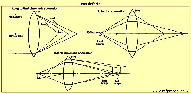
図5レンズの欠陥
解決策
微細構造の詳細を見るには、適切な解像度、つまり解像力、および適切な画像コントラストを生成するための光学システムが必要です。解像度は許容できるがコントラストが不足している場合、詳細を観察することはできません。一般に、距離「d」で隔てられた2つの点または線を解決する能力は、入射光の波長「l」と開口数NA 、の関数です。 目的の。これは、方程式「d =k.l / NA」に従います。ここで、kは0.5または0.61です。図6は、k=0.61と4つの光の波長に対するこの関係を示しています。他の公式も報告されています。この方程式には、対物レンズの補正の程度や顕微鏡を通して見ている人の視力など、解像度に影響を与える他の要因は含まれていません。これは、自発光点、完全な白黒コントラスト、透過光検査、理想的な点光源、レンズの欠陥がないなど、金属組織学には存在しない条件下でのアッベの研究に基づいています。
前の段落の式を使用すると、NAが1.4の対物レンズの分解能の限界は約0.2マイクロメートルです。 0.2マイクロメートル離れた線や点を見るには、必要な倍率は、対物レンズの解像力を人間の目の解像力で割ることによって決定されます。これは、観察条件下では決定するのが困難です。アッベは、最適な視界を得るために、目からの距離である250mmの距離で0.3mmの値を使用しました。平均波長が0.55マイクロメートルの光の場合、必要な倍率は対物レンズのNAの1,100倍です。これが、最大有効倍率の1,000NAルールの原点です。 1,000 NAを超える倍率は、「空」または役に立たないと呼ばれます。
1,000 NAの規則を厳密に順守することは、それが開発された条件を考慮すると疑問視されるべきであり、それは金属組織学で遭遇する条件とは確かに大きく異なります。アッベの分析によると、最適な20/20の視力、最適なコントラスト条件、平均光波長550 nmの光学顕微鏡を使用している人の場合、対物レンズのNAを最大限に活用する最低倍率はNAの550倍です。 。 これにより、特定の対物レンズで使用するための有用な最小倍率が確立されます。光学顕微鏡を使用する平均的な人の有用な倍率の上限は2,200NA、であることが示唆されています。 1,000NAではありません。
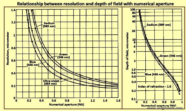
図6開口数による解像度と被写界深度の関係
被写界深度
被写界深度は、画像の詳細が許容できる鮮明さで観察される光軸に沿った距離です。解像度に影響を与えるこれらの要因は、被写界深度にも影響しますが、反対方向です。したがって、これら2つのパラメータの間で妥協点に到達する必要があります。これらのパラメータは、倍率が上がるにつれて難しくなります。これが、高倍率検査にライトエッチングが好まれる理由の1つです。
検査モード
選択した対物レンズの解像度を実現するには、画像のコントラストが適切である必要があります。画像のコントラストは、サンプルの準備と光学系に依存します。サンプル表面からの光反射率の違いは、拡大後に目に見える振幅の特徴を生み出します。光の反射によって生じる位相差は、顕微鏡への位相差または干渉コントラストのアタッチメントを使用して可視化されます。
明視野照明 –最も広く使用されている観察方法である明視野垂直照明は、撮影された顕微鏡写真の大部分を占めています。動作中、光は対物レンズを通過し、サンプル表面に垂直に当たります。入射光に垂直な表面の特徴は、対物レンズを通して接眼レンズに光を反射し、そこで表面の特徴は明るく見えます。光ビームに対して斜めの表面は、角度に応じて、対物レンズに反射する光が少なくなり、暗く見えます。
斜めの照明 –一部の顕微鏡では、コンデンサーアセンブリまたはミラーを偏心させて、対物レンズを通過する光が非垂直角度でサンプル表面に当たるようにすることができます。サンプル表面の粗さが影を落とし、立体的な外観を生み出します。これにより、浮き彫りになっている、または凹んでいるフィーチャを判別できます。ただし、この手法では照明が不均一になり、解像度が低下するため、斜めになることはほとんどありません。
暗視野照明の場合 –暗視野照明では、斜めに向けられたフィーチャから反射された光が収集され、入射ビームに垂直なフィーチャから反射された光線がブロックされます。したがって、コントラストは本質的に明視野照明のコントラストとは逆になります。つまり、明視野照明で明るいフィーチャは暗く表示され、通常は暗いフィーチャは明るく表示されます。これにより、非常に強い画像コントラストが生成され、斜めの特徴が明るく見えます。このような条件下では、明視野照明を使用して見えない特徴を見ることができることがよくあります。この方法は、粒子構造の研究に特に役立ちます。ただし、光の強度が低いため、顕微鏡検査がより困難になり、自動露出制御デバイスを使用することで問題が軽減されます。
偏光 –金属組織学で使用される偏光は、通常、ベリリウム、アルファチタン、ジルコニウム、ウランなどの特定の光学異方性金属の観察に限定されていました。これらの金属は、エッチングが困難ですが、適切に研磨すると偏光によく反応します。 Before development of the electron micro-probe analyzer (EMPA) and energy dispersive spectroscopy (EDS), polarized light examination was an integral part of the method for identifying inclusions. Since the development of these instruments, polarized light has been used less frequently for this purpose, since identification with the EMPA or EDS techniques is more definitive. Most metallurgical microscopes now use synthetic Polaroid filters. The ‘polarizer’ is placed in the light path before the objective, and the ‘analyzer’ is placed in the light path after the objective, normally just below the eyepiece.
Light consists of transverse waves vibrating in all directions at right angles to the direction of propagation. These vibrations occur symmetrically around the direction of propagation and are unpolarized. When light passes through a polarizing filter, the vibrations occur in only one plane in the direction of propagation, and the light is termed plane polarized. This plane changes as the filter is rotated. When the analyzer filter is placed in the light path, plane polarized light passes through it if the plane of vibration of the light is parallel to the plane of vibration of the analyzer. If the plane of vibration of the analyzer is perpendicular to that of the light the light does not pass through, and extinction results. When plane-polarized light is reflected from the surface of an isotropic metal (any metal with a cubic crystallographic structure, such as iron), then passes through the analyzer in the crossed position (plane of vibration perpendicular to that of the plane-polarized light), the image is extinguished, or dark. However, in practice, since the metallurgical microscope does not produce perfectly plane-polarized light, complete extinction does not occur. This is not a serious problem, since polarized light is used only in a qualitative manner in metallography. Strain-free objectives, normally achromats, are to be used. Fluorite or apochromatic objectives are unsuitable. A strong white-light source is needed to produce accurate colour effects.
If an optically anisotropic, polished metal is placed under the light beam with the polarizer and analyzer crossed, the microstructure is revealed. The quality of sample preparation is very important, and the surface is to be perpendicular to the light path. Rotation of the sample under the beam changes light intensity and colour. Since it is difficult to set the polarizer and analyzer in the crossed position accurately when an anisotropic sample is in place unless the crossed positions are marked on the polarizer and the analyzer, it is best to find this position first using an isotropic sample.
When plane-polarized light strikes an anisotropic metal surface, reflection occurs as two plane-polarized components at right angles to each other. The directions vary with crystal structure. The strength of these two perpendicular reflections can change, and a phase difference exists between them. These differences vary with each metal and depend on the crystal orientation. No reflection is obtained when the basal plane of hexagonal or tetragonal crystals is perpendicular to the light beam. Maximum reflectance occurs when the principal symmetry axis of the crystal is perpendicular to the light beam. The resultant image is predominantly influenced by these orientation effects with phase differences are of little significance.
When the analyzer is crossed with respect to the polarizer, rotation of plane-polarized light from the anisotropic surface allows the light to pass through the analyzer, producing an image in which each grain has a different light intensity and colour, depending on its crystal orientation relative to the light beam. As the stage is rotated, each grain changes four times in intensity from light to dark during a 360 degree rotation. If the phase difference is appreciable, the light is elliptically polarized, the difference in intensity in each grain with rotation is less, and extinction is not observed. Colour images are obtained when the reflected plane-polarized light varies with wavelength. When little colour is present, a sensitive tint plate inserted between the polarizer and the objective enhance colouration.
Isotropic metals can be examined using crossed-polarized light if the surface can be rendered optically active by etching, staining, or anodizing. Procedures have been developed for several metals, however, all etched surfaces do not respond to polarized light. Normally, the etch s to produce etch pits or facets in each grain to cause double reflection at these features. Grains with different crystal orientations produce differently oriented pits or facets, yielding different degrees of elliptical polarization and hence varying light intensity. Anodizing produces a thick oxide film on the sample surface and irregularities in the film lead to double reflection.
Although the polarization response of anodized samples has been attributed to optical anisotropy of the film, experimentation has shown that the effect is due to film surface irregularities. Tint etchants produce surface films which result in interference colours which can be enhanced using polarized light. In general, best results are achieved when the analyzer is shifted slightly from the crossed position. In addition to its use in examining inclusions, anisotropic metals (antimony, beryllium, bismuth, cadmium, cobalt, magnesium, scandium, tellurium, tin, titanium, uranium, zinc, and zirconium, for example), and etched / anodized/ tint-etched cubic metals, polarized light is useful for examination of coated or deformed metals. Phase identification can also be aided in some cases. The internal structure of graphite nodules in cast iron is vividly revealed using polarized light. Martensitic structures are frequently better revealed using polarized light, which illustrate lath martensite in a high-strength iron-base alloy.
Phase contrast illumination – It permits examination of subtle phase variations in microstructures with little or no amplitude contrast from differences in the optical path at the surface (reflected light) or from differences in the optical path through the sample (transmitted light). Differences of height as small as 0.005 micrometers can be detected. Application of phase-contrast illumination in metallography has been limited. The technique needs a separate set of objectives and a special vertical illuminator.
Interference-contrast illumination – Differential interference-contrast illumination produces images with emphasized topographic detail similar to those observed using oblique illumination. Detail which is invisible or faintly visible using bright-field illumination can be revealed vividly with interference-contrast illumination. Examples of the topographic detail which can be revealed using differential interference-contrast illumination are the relative hardness of the constituents or the nature of the etching process, that is, which areas or constituents are attacked by the etchant. In some cases, other aspects of the structure can be revealed which are invisible or faintly visible in bright-field illumination.
Interference techniques – Several interference techniques are used to measure height differences on samples. Interference fringes on a perfectly flat surface appear as straight, parallel lines of equal width and spacing. Height variations cause these fringes to appear curved or jagged, depending on the unit used. The interference microscope divides the light from a single point source into two or more waves which are superimposed after traveling different paths. This produces interference. Two-beam and multiple-beam instruments are the two basic types of interferometers used. The measurements are based on the wavelength of the light used. Two-beam interferometers can measure height differences as small as ‘l’/20; multiple-beam interferometers, as small as ‘l’/200.
The Linnik-type interferometer is a two-beam reflecting microscope which uses non-polarized light. A beam-splitting prism produces two light beams from a monochromatic light source. One beam travels through the test piece objective to the test piece surface and is reflected back through the objective to the eyepiece. The other beam travels through the reference objective, strikes an optically flat reference mirror, and returns to the beam splitter, then to the eyepiece. If the path difference between the two beams is not equal or not a multiple of ‘l’/2, interference occurs and contour lines are formed which indicate locations of equal elevation. The height difference between adjacent fringes is ‘l’/2.
The Tolansky multiple-beam interferometer produces interference between many light beams by placing a reference mirror which is partially transmitting and partially reflecting very near the sample surface but slightly out of parallel. The reference mirror has a known reflectivity selected to approximate that of the surface. Light passes through the reference mirror and strikes the sample surface, is reflected by the sample surface, and interferes with the rays reflected between the reference mirror and the sample. The fringes produced by the multiple-beam interferometer are sharper than those from the two-beam interferometer, which accounts for the greater accuracy. The distance between the fringes is also ’l’/2. Elevations produce displacements of the fringes from parallel alignment. The displacement is compared to the distance between the fringes to obtain height measurements.
Light-section microscopy – The light-section microscope, also used to measure surface topography, complements interference techniques. Roughness differences from 1 micrometer to 400 micrometers can be measured, which is useful in examining machined surfaces and for measurement of surface layers or films. In operation, a slit is placed near the field iris in the illumination system and is imaged by an objective as a light line on the surface to be measured. Oblique illumination is used with a dark background. The light band is observed using a second objective which is identical to the first. The objectives are 45 degrees to the sample surface and 90 degrees to each other. A reticle in the eyepiece is used for measurements, or they are made on photographs. Vertical resolution is not as good as with interferometers, but lateral resolution is better.
Auxiliary techniques
Several special devices can be used with the optical microscope to get additional information. These techniques are described below.
Micro-hardness testing – Micro-indentation hardness data can be obtained by adding indenter attachments to the microscope. Single-purpose units also are made by many manufacturers of hardness test equipment. Loads are normally made from 1 g (gram) to 1,000 g, although some manufacturers have units for low loads (0.05 g to 200 g). Knoop or Vickers indenters can be used.
Hot-stage microscopy – Hot-stage microscope cells are available from several manufacturers. Single-purpose units can also be used. Cold-cell attachments have also been produced, but have rather limited use in metallography. The hot-stage microscope has been used to study phase transformations on heating or cooling or at constant temperature. Examination of reactions in the hot-stage microscope cell needs use of long-working-distance objectives, since the sample is held within the cell. Moreover, since the cell window is quartz, the objectives is to be quartz-corrected, especially those with magnifications of 20× or more.
Techniques other than chemical etching are to be used to view phase changes. Grain boundaries are to be thermally etched if the sample is held at a constant temperature in the vacuum. Grain-boundary grooving is easily observed using bright field illumination. Phase transformations are visible by the relief produced at the surface. Hence, shear reactions, such as those produced by martensite or bainite formation, are most easily observed. Other phase transformations are more difficult or impossible to observe. Transformations can be photographed in situ, for which motion picture cameras are normally used.
Special stages – These are available in a variety of configurations. Auto leveling stages for mounted samples are a typical example. Universal tilting stages have also been made for rapid manipulation of rough, irregular samples. Special stages have also been designed for handling small objects. A number of stages have been made for performing in situ experiments. Basic studies of solidification have been performed by in situ observation of the freezing of low-melting-point organic materials, such as camphene, which solidify like metals. Observation of the recrystallization of low-melting-point metals and alloys has been similarly observed. Special stages have been used to observe the progress of electrolytic polishing and etching. Cells have also been used for in situ examination of corrosion processes. Stages have been designed to observe a variety of processes involving static or dynamic stress, and devices have also been designed to permit physical extraction of inclusions.
Hot-cell microscopy – Metallographic preparation of radioactive materials needs remote-control preparation using specially designed hot cells. Special microscopes have been designed for use with the hot cell.
Field microscopy – When the microstructure of a component or large object which cannot be cut and moved to the laboratory is to be examined, portable laboratory equipment, made by several manufacturers, can be used to polish a section in situ. A portable microscope can be sometimes used to examine and photograph the microstructure. If this cannot be done, replicas can be made and examined using an optical microscope or an electron microscope.
Comparison microscopes – The need occasionally arises to compare two microstructures. Normally, this is carried out by placing micrographs from each sample side-by-side, but it can also be performed using special microscopes. A bridge comparator is used to combine images from two bench microscopes for simultaneous viewing.
Television monitors – Projection microscopes can be used for group viewing, but it is more common to display the microstructure on a black-and-white or colour monitor. A number of high-resolution closed-circuit systems are available.
Clean-room microscopy – The study of small particles is influenced by dust contamination during viewing. Hence, such work is to be performed in a clean box, clean bench, or clean room which is specially made to provide a dust free environment.
Image analyzers – The increased use of quantitative metallography, particularly for characterization of inclusions, has promoted development of automated image analysis systems based on television principles. Phases or constituents of interest are detected primarily by differences in light reflectivity which produce gray-level differences on the monitor. Majority of the stereological measurements can be made using these systems. Considerable automation has been achieved using automated stages and powerful minicomputers. Although these devices can be quite expensive, they have stimulated interest in stereology and its application to structure-property correlations.
Features are detected on as-polished or etched samples, depending on the nature of the feature of interest. If etching is needed, selective techniques are normally used. Field and feature-specific measurements are utilized. Field measurements measure all the detected features simultaneously, as in volume fraction measurements. In feature-specific measurements, each separate particle is measured sequentially. This procedure is normally used for shape and size measurements.
Some structures do not lend themselves to accurate measurements using such systems. For example, quantification of fracture surface detail cannot be performed using an automatic image analyzer, since the device cannot separate fracture features by gray level. Many transmission electron micrograph structures also cannot be analyzed using these devices. For such structures, semi-automatic tracing devices can be used with the operator performing detection with a light pen or stylus. These lower-cost systems can be used for nearly any stereological measurement. Because of the greater time needed for detection, they are less suitable for measurement problems which need sampling of many fields.
Photo-microscopy
Prior to the development of photographic attachments, microstructures were to be sketched. Although the need for such documentation is no more there, sketching remains useful as a teaching method. Photo-microscopy is important in metallography, since the photo-micrograph can faithfully reproduce the detail observed for others to view. With the equipment presently available, high-quality micrographs are easily produced. However, this needs careful attention to sample preparation, etching, and use of the microscope. Reproduction of false microstructures is all too common and has caused inaccurate interpretations, rejection of good materials, and faulty conclusions in failure analyses.
Historically, darkroom photographic procedures have been most prevalent. Since the introduction of instant photographic processes such as Polaroid, however, many photo-micrographs have been made using these materials, taking advantage of their speed and efficiency. However, image reproduction is sacrificed, and the process is to be repeated for each extra copy. Use of an automatic exposure device is necessary with instant process film to minimize waste. Traditional darkroom photographic methods need more effort, but yield better micrographs. Considerable automation in wet darkroom processes is possible, but frequent use of photo-microscopy is needed to justify the cost of such equipment.
Obtaining good micrographs needs adequate image contrast and resolution, uniform focus over the entire field, uniform lighting, and adequate depth of field. The light source is to be properly aligned, and the system is to be free of vibration. The yellow-green filter is to be employed to correct lens defects. The optics is to be clean, and the field and aperture diaphragms are to be adjusted correctly. The microscope is focused in a variety of ways, depending on the model. Several film formats can be used, such as plates, sheet film of different size, or 35-mm roll film. The magnification at the film plane is to be known. This is a simple procedure if the only variables are the objective and eyepiece magnification, but is more difficult when using a zoom system or bellows. A stage micrometer can be utilized to determine the true magnification.
A range of black-and-white and colour films is available for darkroom or instant techniques. The manufacturers of these films document film characteristics. Black-and-white films are normally used due to their lower cost. They show better contrast control, are easier to process, and are normally quicker to use than colour films. Colour film has some important uses for which its cost is justified. In traditional black-and-white photography, a negative image is produced first and is used to produce a positive image of the microstructure on suitable paper. The micrograph lasts for many years without any apparent change. Selection of the negative film is based on the format available, colour sensitivity, contrast, resolving power, speed, graininess, and exposure and development latitudes.
Some black-and-white films are not sensitive to the entire visible spectrum. Orthochromatic films are sensitive to all colours except orange and red. Panchromatic films are sensitive to all colours, although they emphasize blue and de-emphasize yellow. A yellow filter can be used to reduce this colour bias.
Orthochromatic films can be developed under dark red light, but panchromatic films need total darkness. Orthochromatic films are very good for photo-microscopy, particularly when a yellow-green filter is inserted to correct lens defects.
Film speed is a critical variable only when illumination is low, as in polarized light, interference-contrast, or dark-field illumination. Orthochromatic film has a medium contrast which is adequate for most structures. Contrast can be enhanced with a high-contrast film. The resolving power of a film defines its ability to record fine details in the image. Hence, a high-resolving-power film is desirable. Graininess depends on the size of the silver grains in the emulsion, the developer used, and the development time and temperature. High-speed films are grainier than low-speed films, making them less suitable for enlarging. Contact printing is preferred. It needs a large film size, but saves enlargement time. It produces better images and eliminates re-determining the magnification of the print. A fine-grain film provides the best resolution.
When a negative is exposed, there is an allowable range of exposures which produces a useful, printable negative. Wide exposure latitude is quite valuable. Each film includes information on its characteristic relationship between exposure time and density. The exposure selected is to be on the linear portion of the density-time curve. A good, dense negative allows suppression of some of the fine image defects during printing. An underexposed negative greatly restricts printing and normally results in a poor print. Development of negatives is rather simple and involves use of a developing solution, a stop bath, a fixing solution, as well as washing and drying.
The correct exposure is most easily determined using a built-in exposure meter. If this is not available, a test exposure series can be made. This is accomplished by pulling out the film slide completely and exposing the entire film for a time judged to be considerably shorter than that needed. The slide is then inserted so that it covers around 10 mm to 20 mm of the film, and the exposure is repeated. This is repeated incrementally until the slide is fully inserted, covering the film. After development, the correct time can be assessed based on the density of the negative in each band.
Alternatively, the step exposure can be performed using an instant film of the same speed, saving the darkroom time. Majority of the black-and-white films are contact printed. The negative is placed emulsion side up on the contact printer, and a suitable paper is placed emulsion side down over the negative. The printer is closed, and light is passed through the film onto the paper. The print is developed, stopped, fixed, washed, and dried. Print contrast is controlled by the type of paper and development time. Print contrast types vary from extra-soft (flat) to extra-contrast (grades 1 to 5). Number 3 paper is used most frequently. Number 4 paper is used to increase contrast, and No. 2 paper to reduce contrast.
Instant process films eliminate the darkroom work, thus hastening the process. Polaroid prints use the diffusion-transfer reversal process. Development begins when the film is removed from the camera after the exposure. The action of pulling the film out of the camera crushes a pod containing the viscous, caustic developer and spreads it over the film. Black-and-white films develop rapidly while the colour prints need slightly more time. Some of the Polaroid films have very high speeds, an advantage in dim lighting. Some prints are to be coated with a neutralizing stabilizer / protective varnish to prevent staining and fading. Also available are instant films which produce a negative and a positive print. This negative is to be cleared, but a darkroom is not required. Polaroid films used in microscopy are all panchromatic. They are available as roll film, film packs, or sheets. Exposure times are to be more accurately controlled to get good prints than with traditional wet-process films.
Macro-photography
Examination and photography are frequently needed for such objects as macro-etched disks and broken parts. Examination can be performed visually or with the aid of a simple hand lens or stereo-microscope. Macro-photography can be performed using majority of the cameras, perhaps aided by the use of close-up lens attachments, a bellows, or a macro-lens. Many stereomicroscopes can be equipped with cameras for photography while some takes stereo-pairs. A few manufacturers offer camera stands for macro-photography. Some metallographs also have low-magnification objectives which can perform certain types of macro-photography.
Macro-photography utilizes magnifications from less than 1× to 50×. Most laboratories, especially those engaged in failure analyses, have various cameras, light sources, and stereo-viewers to cover the wide range of objects photographed. Correct lighting is necessary to emphasize details and provide even illumination without glare or reflection. Adjustment of lighting needs some experimentation and experience. Available lighting includes flood lamps, rings, coaxial, or fiber optics. A light box is useful for eliminating shadows, but considerable creativity is needed to achieve good results.
Depth of field and resolution are important variables. Many of the objects to be photographed are three-dimensional, which needs a certain depth of field and proper lighting to reveal shape and texture. Depth of field varies with the aperture diaphragm lens setting, the magnification, and the focal length of the lens. Stopping down the aperture improves depth of field, but decreases image brightness and clarity. Depth of field also increases as magnification decreases and focal length increases. For magnifications below 5×, focal lengths of 100 mm or more are preferred. Shorter-focal-length lenses are used for higher magnifications.
製造プロセス