


非破壊検査技術
非破壊検査技術
結晶格子の欠陥により、材料に固有の微視的な欠陥が存在する可能性があります。また、溶接、鋳造、鍛造、表面処理などの製造工程では、さらに欠陥や欠陥が発生する可能性があります。さらに、材料は、応力、疲労、および腐食のさまざまな条件下で使用され、追加の欠陥を作成したり、現在の欠陥を悪化させたりする可能性があります。材料の破損は通常、これらの欠陥が危険な比率に達し、材料の残りの部分が受ける応力に耐えられなくなり、延性または脆性になるときに発生します。したがって、材料のこれらの欠陥を検出し、それらの性質、サイズ、および場所の観点からそれらを評価する必要があります。材料が受け入れられるか、修理後に受け入れられるか、または拒否されて廃棄されるかを決定するために、欠陥の重大度を評価するためのさらなるステップが必要です。
非破壊検査(NDT)は、部品またはシステムの保守性を損なうことなく、不連続性または特性の違いとしても知られる欠陥について、材料、コンポーネント、またはアセンブリを検査、テスト、または評価する手法です。つまり、検査やテストが完了しても、部品は引き続き使用できます。この手法は、個別の調査のためにサンプリングベースで適用することも、生産品質管理システムで材料を100%チェックするために使用することもできます。表面の質感、製品の完全性、将来の有用性を損なうことなく、材料や構造を検査および/または測定することが可能です。
NDTは高度な技術コンセプトですが、機器の進化により、製造のあらゆる段階のあらゆる産業環境でのアプリケーションに十分な堅牢性がもたらされました。その用途は、鉄鋼生産からすでに使用されているコンポーネントの現場検査にまで及びます。製品に関する最大量の情報を達成し、その結果として生産施設にフィードバックするためには、NDT技術を適切に適用するためにある程度のスキルが必要です。 NDTは、標準以下の材料を拒否するための方法であるだけでなく、想定される良好な材料が良好であると判断する保証でもあります。この手法では、さまざまな原則が使用されます。すべての状況ですべての要件を満たすためにブラックボックスを構築できる単一の方法はありません
NDTの分野は非常に広範で学際的であり、構造コンポーネントとシステムの検査で重要な役割を果たし、信頼できる方法で機能を実行します。また、NDTテストの信頼性を保証し、使用する機器の故障、方法の誤用、検査官のスキルと知識による特定のエラーを防ぐために、特定の基準が作成されています。 NDTテストが成功すると、材料の状態や欠陥を特定して特性を明らかにすることができます。 NDT技術は通常、かなりのオペレータースキルを必要とし、結果は主観的である可能性があるため、テスト結果を正確に解釈することは困難な場合があります。
NDT技術名は、多くの場合、浸透媒体のタイプまたはテストの実行に使用される機器を指します。 NDT技術は、従来の技術と非従来の技術に分類できます。従来のNDT技術には、(i)目視検査または光学検査、(ii)液体浸透探傷試験、(iii)磁粉探傷試験、(iv)渦電流試験、(v)X線検査、および(vi)超音波試験が含まれます。非従来型のNDT技術は、特殊なアプリケーションにのみ使用され、中性子ラジオグラフィー、アコースティックエミッション、赤外線テスト、マイクロ波技術、リークテスト、ホログラフィー、誘導波テスト、地中レーダー、レーザーテストなどが含まれます。
ほとんどのNDT技術に共通する重要な要素は、(i)プロービング媒体、(ii)不連続性を検出できるように使用されている媒体に適したテストサンプル、(iii)分布を測定できる検出器、またはメディアの変更、(iv)評価に適した、検出器から受け取った情報を記録または表示するための手法、および(v)結果を評価するために検出器のフィードバックを解釈するように訓練されたオペレーター。
NDA手法は、テスト中に指標を提供します。 NDTに適用される「適応症」という用語の定義は、「NDTを通じて開示された応答または応答の証拠であり、その真の重要性を判断するにはさらに評価が必要です」。特定のNDT技術が部品に適用されると、応答があります。この応答は指標です。 「応答」という用語は、(i)液体浸透探傷試験を実行するときの「ブリードアウト」、(ii)磁粉探傷試験を実行するときの粒子の蓄積、(iii)場合の放射線写真フィルムの密度の変化を意味することを意図しています。 X線検査、(iv)超音波検査を実行するときの信号、および(v)渦電流検査を実行するときのメーターのたわみ、信号、またはデジタル変化。応答が観察されたら、テストを実行するオペレーターはそれを解釈し、それを(i)誤った、(ii)関連性のない、または(iii)関連性のあるまたは真の不連続性のいずれかの兆候のグループに分類する必要があります。
考えられるすべての問題の解決策を提供するNDT手法はありません。つまり、これらはオプションの代替手段ではなく、相互に補完的です。基本的な原則、典型的なアプリケーション、従来の手法の利点と制限を以下に説明します。
目視または光学検査
目視および光学検査技術(図1)を使用して、コンポーネントの表面状態を検査します。視覚的テストは、考えられるほぼすべての表面状態に広く使用されています。その性質上、視覚的および光学的テストは単純で簡単です。最も単純な方法では、機器を使用せずに、適切な光の中でオペレーターがクリーンなコンポーネントを検査できます。これは非常に簡単です。多くの場合、オペレーターは検査を支援するために光学機器を使用する必要があります。これは、手持ち式の拡大鏡レンズから柔軟なファイバースコープ、またはリモートビデオシステムまでさまざまです。
経験豊富なオペレーターは、最適な条件下で、小さなきつい亀裂でも検出できます。ただし、再現性には問題があります。条件が最適化されていない場合、同じオペレーターが繰り返し検査で同じコンポーネントの同じ亀裂を見逃す可能性があります。このため、オペレーターが障害状態をできるだけ頻繁に見つけることができるようにするために、光学補助装置が頻繁に使用されます。検査は、適切な照明を備えた清潔で快適な環境で行う必要があります。
安全性、作業位置、および大気条件に注意を払う必要があります。検査には、オペレーターによるかなりの集中力が必要です。照明は非常に重要であり、結果に大きな影響を与える可能性があります。自然光は、目視検査を実行するのに最適なタイプの光です。人工光は目視検査にも使用できますが、オペレーターは、使用されている仕様または手順に記載されている正しい光レベルを確認する必要があります。
コンポーネントは清潔で保護コーティングがないようにする必要があります。たとえば、汚れや塗料が求められている表面状態を覆い隠す可能性があります。目視検査を行う前に、オペレーターが十分な訓練と経験を持っていることが非常に重要です。オペレーターも視力が良いです。知られているように、目は素晴らしく洗練された楽器ですが、すべてを見るわけではありません。光を網膜に集中させ、光を神経インパルスに変換して脳に送るように設計されています。次に、脳はこの情報を処理し、見られる画像を形成します。これは私たちを知覚に導きます。それは、物理的な現実と検査官が見ていると思う見方の違いです。検査官が異なれば、目から入ってくる情報の解釈も異なるため、同じ物理的なシーンの見方も少し異なります。
ミュラー・リヤー錯視(図1)は、知覚と現実の違いを示しています。 2つの矢印のシャフトは同じ長さですが、異なっているように見えます。 2人の検査官の知覚の違いは、訓練と経験、および観察が行われたときの観察者の精神的および肉体的状態に依存します。知覚は倦怠感と健康の影響を受ける可能性があります。倦怠感は、観察者の効率と視覚能力を低下させます。これらの問題は、物理データの不正確な解釈につながります。理想的な検査とは、トレーニング、経験、照明、環境条件などのすべての要素が最適化されている検査です。
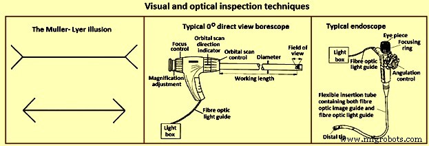
図1視覚的および光学的検査技術
大まかに言えば、目視検査は2種類の表示技術に分けられます。最初のテクニックは直接表示です。このタイプのオブジェクトの表示では、オブジェクトはオペレーターのすぐそばにあります。これは、支援なしで、または機器を使用して行うことができます。 2つ目はリモートビューイングです。この場合、オブジェクトの表示は、オペレーターのすぐそばでは行われません。これは、特別な機器を使用して行われます。
目視検査は、事実上すべてにうまく適用できます。腐食や亀裂などの不連続性から、塗装面のまだら効果まで、さまざまな種類の表面状態を特定するために使用できます。経験豊富な熱処理オペレーターは、白熱光に加熱された後の外観からコンポーネントの温度を推定することもできます。たとえば、鈍いチェリーレッド鋼は約550℃です。
小さな不連続点を見つけるために、オペレーターが頻繁に必要になります。これは肉眼では非常に難しい場合があるため、光学補助具が必要です。最も一般的な光学補助装置のいくつかは、(i)手持ち倍率(通常1.5倍から10倍まで)、(ii)アングルポイズなどの表面状態を測定できるようにする測定スケールを組み込んだ測定拡大鏡です。最大10倍の倍率を持ち、均一な照明を提供するために円形の蛍光管が組み込まれていることが多い拡大鏡、(iii)さまざまなタイプでさまざまな倍率範囲の顕微鏡、(iv)優れた部品である剛性ボアスコープチューブやパイプの内部を検査するための機器(図1)、(v)ライトガイドとイメージガイドの両方に光ファイバーを使用しているため、ボアスコープよりも柔軟性のある内視鏡(図1)と呼ばれる同様のデバイス、および( vi)画質を向上させるために、ボアスコープの光学システムをミニチュアビデオカメラに置き換えることができます。このカメラには、電子ビームを使用して光伝導性ターゲットをスキャンするイメージチューブを含めることができます。 nsor、または代わりに、電荷結合デバイスや電荷注入デバイスなどの固体イメージングデバイスを含めることができます。
液体浸透剤テスト
液体浸透探傷試験の基本原理(図2)は、非常に低粘度(高流動性)の液体(浸透剤)を部品の表面に塗布すると、表面に開いた亀裂や空隙に浸透することです。余分な浸透剤が除去されると、それらのボイドに閉じ込められた浸透剤が逆流し、表示を作成します。浸透探傷試験は、磁性材料と非磁性材料で実行できますが、多孔質材料ではうまく機能しません。
感度を下げ、コストを下げるために、液体浸透探傷試験は、(i)乳化後の蛍光染料浸透探傷試験、(ii)溶媒除去可能な蛍光染料浸透探傷試験、(iii)水洗可能な蛍光染料浸透探傷試験、(iv)乳化後の可視浸透探傷試験としてリストできます。染料浸透剤、(v)溶剤除去可能な可視染料浸透剤、および(vi)水洗可能な可視染料浸透剤。
液体浸透剤試験の利点は、(i)比較的低コスト、(ii)携帯性の高いNDT技術、(iii)細かくてタイトな不連続性に非常に敏感、(iv)さまざまな材料に適用可能、(v)大面積検査です。 。液体浸透技術の限界は、(i)試験面にすべての汚れ、油、グリース、塗料、錆などがないこと、(ii)表面の不連続性のみを検出すること、(iii)多孔質で非常に使用できないことです。粗い表面、(iv)テスト後のすべての浸透物質の除去が頻繁に必要であり、(v)永続的な記録を作成する簡単な方法はありません。
この手法では、浸透剤を「可視」にすることができます。つまり、周囲光または蛍光灯で見ることができ、「ブラック」ライトを使用する必要があります。目に見える浸透探傷試験のプロセスを図2に示します。液体浸透探傷試験を実施する場合、試験する表面が清潔で、浸透探傷試験が表面に開いている空隙や亀裂に入るのを妨げる可能性のある異物や液体がないことが不可欠です。一部。浸透剤を塗布した後、指定された時間(浸透剤の滞留時間)表面にとどまらせ、次に部品を注意深く洗浄して、表面から余分な浸透剤を取り除きます。浸透剤を除去する場合、オペレーターは、空隙に流れ込んだ浸透剤を除去しないように注意する必要があります。次に、現像液の薄いコーティングが表面に塗布され、ボイドまたは亀裂からの浸透剤が現像液に浸透して目に見える表示を作成できるようにするための時間が提供される(現像液滞留時間)。所定の現像剤滞留時間に続いて、部品は視覚的に、または蛍光浸透剤のブラックライトの助けを借りて検査されます。開発者の大多数は、使用されている浸透剤と色のコントラストを提供する、きめの細かい白いタルカムのような粉末です。
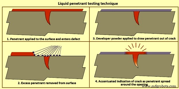
図2液体浸透剤試験技術
溶剤除去浸透剤は、過剰な浸透剤を除去するために水以外の溶媒を必要とする浸透剤です。これらの浸透剤は通常、自然界で目に見え、通常は明るい赤色に染められており、白色の現像液とは対照的です。通常、浸透剤は部品にスプレーまたはブラッシングされ、浸透剤の滞留時間が経過した後、浸透剤クリーナーで湿らせた布で部品を洗浄し、その後、現像液を塗布します。開発者の滞留時間に続いて、部品を調べて、開発者を通して現れる浸透探傷試験を検出します。
水洗可能な浸透剤は、浸透剤に乳化剤が含まれており、水スプレーを使用して浸透剤を除去することができます。それらは浸透探傷タンクに部品を浸すことによって最も頻繁に適用されますが、浸透探傷はスプレーまたはブラッシングによって大きな部品に適用することができます。部品が浸透剤で完全に覆われると、部品は浸透剤の滞留時間の間ドレンボード上に置かれ、次にリンスステーションに運ばれ、そこでコースウォータースプレーで洗浄されて余分な浸透剤が除去されます。余分な浸透剤が除去されたら、水が除去されるまで、部品を温風乾燥機または穏やかなファンの前に置くことができます。次に、部品を乾式現像槽に入れて現像液でコーティングするか、残りの滞留時間放置してから検査します。
乳化後の浸透剤は、水洗可能な浸透剤のように、化学組成に乳化剤が含まれていない浸透剤です。乳化後の浸透剤も同様の方法で塗布しますが、水洗工程の前に、乳化剤を所定の時間(乳化剤の滞留時間)表面に塗布して、余分な浸透剤を除去します。乳化剤の滞留時間が経過すると、部品は水洗可能な浸透剤に使用されるのと同じ水洗および現像プロセスにかけられます。乳化剤は、親油性(油性)または親水性(水性)にすることができます。
磁粉探傷試験
磁粉探傷試験では、1つまたは複数の磁場を使用して、磁性材料の表面および表面近くの不連続性を特定します。これは、磁性材料の表面およびわずかな表面下の不連続性または欠陥を特定するために使用されます。磁化された部品に存在するそのような欠陥は、磁場、すなわち磁束を部品から離れさせる。磁性粒子がこの表面に適用される場合、それらは視覚的な表示を与えるために磁束漏れによって所定の位置に保持されます。磁粉探傷試験にはいくつかの異なる方法を使用できますが、それらはすべてこの同じ一般原理に依存しています。したがって、磁粉探傷試験は、部品に磁場を発生させ、磁性粒子を試験面に適用することによって実施されます。
磁場は永久磁石または電磁石で加えることができます。電磁石を使用する場合、電界は電流が印加されているときにのみ存在します。磁場が磁場の方向を横切る不連続性に遭遇すると、図3に示すように、磁束線が独自の磁束漏れ磁場を生成します。これは、非常に微細な色の強磁性粒子(磁性粒子)の場合に見られます。 )は部品の表面に適用され、粒子は不連続部に引き込まれ、エアギャップを減らし、部品の表面に目に見える表示を生成します。磁性粒子は、乾燥粉末または液体溶液に懸濁することができ、紫外線(ブラック)光の下で蛍光を発する可視染料または蛍光染料で着色することができます。
交流(AC)または直流(DC)のいずれかを使用して磁場を誘導することができます。 「表皮効果」によってACによって生成される磁場は、テストオブジェクトの表面で最も強くなります。 ACはまた、部品の表面でより大きな粒子移動性を提供し、部品の表面が不規則であっても、粒子が自由に動き回って磁束漏れの領域を特定できるようにします。 DCは、より大きな透過力を持つ磁場を誘導し、表面近くの不連続性を検出するために使用できます。
現場検査の大部分はヨークを使用して行われます(図3)。中央のコアに電気コイルが巻かれ、電流が流れると磁場が発生し、コアから関節脚を通って部品に伸びます。これは、磁束線が一方の脚からもう一方の脚に伸びているため、縦磁化として知られています。脚を強磁性部品に配置し、ヨークに通電すると、部品に磁場が発生します。磁束線は一方の脚からもう一方の脚に伸びているため、脚の間に引かれた線に垂直に向けられた不連続性を見つけることができます。表示を見逃さないように、ヨークは図のような位置で一度使用した後、ヨークを90度回転させて再度使用するため、表示を見逃すことはありません。すべての電流がヨークに含まれ、磁場のみが部品を貫通するため、このタイプのアプリケーションは間接誘導とも呼ばれます。
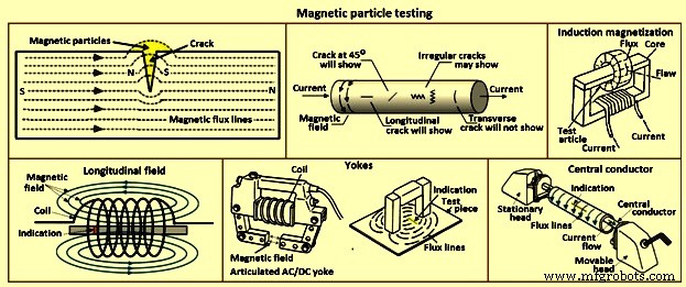
図3磁粉探傷試験
ポークユニットは、図3に示すように、電流が部品を流れ、脚の周りに円形の磁場が生成される直接誘導を使用します。ポーク間の磁場は、ポーク間に引かれた線に対して垂直に移動するため、表示は平行になります。ポークの間に引かれた線に見つけることができます。ヨークと同様に、2回の検査が行われ、2回目は、最初のアプリケーションに対して90度の方向を向いたポークを使用します。
電気コイルは、縦方向の磁場を生成するために使用されます。電流が流れると、コイルを構成するワイヤの周りに磁場が発生し、結果として生じる磁束線がコイルを通過するようになります。縦方向の磁場のため、コイルに配置された部品の表示は縦方向の磁場を横切る方向に向けられます。
横型ウェットバスマシン(ベンチユニット)の大部分は、コイルとヘッドのセットの両方を備えており、電流を流して磁場を発生させることができます。これらの機械は、溶液中で蛍光磁性粒子を使用するため、「ウェットバス」という名前が付けられています。ヘッド間で部品を試験する場合、部品をヘッド間に配置し、可動ヘッドを上に動かして、試験対象の部品をヘッド間でしっかりと保持し、磁性粒子を含む浴液で部品を濡らし、粒子がパーツ上を流れている間に電流が印加されます。電流は頭から頭へと流れ、磁場は電流に対して90度の方向を向いているため、頭の間の線に平行に方向付けられた表示が表示されます。このタイプの検査は通常、「ヘッドショット」と呼ばれます。
パイプ、チューブ、フィッティングなどの中空部品をテストする場合、図3に示すように、導電性の円形バーをヘッドの間に配置し、部品をバー(中心導体)に吊るします。次に、部品を浴液で濡らします。電流が印加され、部品ではなく中心導体を通過します。次に、部品のIDとODを検査できます。ヘッドショットの場合と同様に、磁場は電流の流れに垂直であり、試験片を包み込むため、この手法を使用して、部品の長さを軸方向に下る兆候を見つけることができます。
磁粉探傷試験の利点は、(i)経済的、(ii)目視試験の補助、(iii)固定または携帯機器の使用、(iv)即時の再現可能な結果の提供、(v)効果的な検査技術、および( vi)コントラストまたは蛍光消耗品。磁粉探傷試験の限界は、(i)検査対象の部品が強磁性である、(ii)大電流が必要、(iii)表面およびわずかに表面下の欠陥のみを検出できる、(iv)部品が必要である、消磁、(v)部品は清潔で比較的滑らかである、(vi)機器はかさばり、重い可能性がある、(vi)電源は通常必要である、(vii)コーティングは表示を隠すことができる、(viii)材料または部品の透過性は結果に影響します。
渦電流探傷
渦電流は、電磁誘導と呼ばれるプロセスによって生成されます。銅線などの導体にACを印加すると、導体内およびその周囲に磁界が発生します。この磁場は、ACが最大になると拡大し、電流がゼロになると崩壊します。別の導電体がこの変化する磁場に近接すると、この2番目の導体に電流が誘導されます。これらの電流は、ボイド、クラック、粒子サイズの変化などの材料の性質、およびコイルと材料の間の物理的距離の影響を受けます。これらの電流は、センサーとして使用される2番目のコイルにインピーダンスを形成します。実際には、プローブは検査対象の部品の表面に配置され、電子機器は同じプローブを通るワークピースの渦電流を監視します。検出回路は送信コイルの一部です。
渦電流技術の主な用途は、表面または表面下の欠陥の検出です。この技術は、製品の材料の導電率、透過性、寸法に敏感です。渦電流は、交番磁界(通常は10 Hz〜10 MHz)にさらされる導電性材料で生成できます。交流磁界は通常、コイルに交流電流を流すことで発生します。コイルは多くの形状をとることができ、10ターンから500ターンのワイヤーを持つことができます。製品で生成される渦電流の大きさは、導電率、透磁率、および設定された形状に依存します。材料または形状の変化は、コイルインピーダンスの変化として励起コイルによって検出できます。
最も単純なコイルは、一端に数ターンの巻線があり、テストする製品の表面近くに配置されたフェライトロッドで構成されています。たとえば、製品の表面に亀裂が発生すると、渦電流が亀裂の周囲をさらに進み、これがインピーダンスの変化によって検出されます(図4)。コイルは、一般に被駆動ペアと呼ばれるペアで使用することもでき、この配置は、差動接続されたコイルで使用できます。このようにして、「リフトオフ」(表面からのプローブの距離)信号を強化することができます。コイルは、1つのコイル巻線が1次側で、1つ(または2つ)のコイル巻線が2次側に使用される変圧器タイプの構成でも使用できます。 。
検出された渦電流信号には、CRT(ブラウン管)タイプのディスプレイに表示できる振幅と位相の情報が含まれています。通常は非デジタルディスプレイです。信号は、実際の信号、つまり絶対信号として表示することも、適切な電子機器を使用して、信号の変化のみを表示することもできます。最良の結果は、1つの製品パラメータのみが変更された場合に達成されます。亀裂の存在。実際には、渦電流信号の変化は、組成、硬度、テクスチャ、形状、導電率、透磁率、および形状の違いによって引き起こされます。場合によっては、亀裂の影響が他のパラメータの変更によって隠され、不要な拒否が発生する可能性があります。ただし、必要に応じて、亀裂、導電性、金属損失などの検出を強化するために、構成、サイズ、およびテスト頻度に応じてコイルを選択できます。
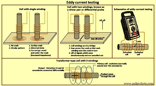
図4渦電流探傷
渦電流が材料に浸透する深さは、テスト周波数を調整することで変更できます。つまり、周波数が高いほど浸透は低くなります。ただし、周波数が低いほど、小さな欠陥に対する感度は低くなります。コイルが大きいほど表面粗さの影響を受けにくく、その逆も同様です。最新の電子ユニットは、アブソリュートモードまたはディファレンシャルモードで、広範囲の周波数で幅広いコイル構成を操作できます。単一または複雑な形状のコンポーネントの亀裂の表面テストには、通常、単一のフェライトコア巻線を備えたコイルが使用されます。プローブはコンポーネントに配置され、電子ユニットコントロールを使用して「バランス」が取られます。プローブをコンポーネントの表面全体でスキャンすると、亀裂を検出できます。
表面を自動的にスキャンする場合は、リフトオフ距離が正確に維持されている場合にのみシングルコイル巻線が適しています。通常、差動コイル構成は、リフトオフ効果、振動効果などを許容範囲でキャンセルできる高速スキャンシステムで使用されます。チューブ、バー、ワイヤーは、包囲コイルを使用して検査できます。これらは通常、1つのプライマリと2つのセカンダリが差動接続されたコイル構成になっています。
渦電流電子機器の大部分は位相表示を備えており、これによりオペレーターは欠陥状態を特定することができます。多くの場合、亀裂、リフトオフ、およびその他のパラメータからの信号を明確に識別できます。 2つ以上の異なるテスト周波数で同時に製品を検査できるユニットも利用できます。これらのユニットを使用すると、特定の不要な効果を電子的にキャンセルして、欠陥の検出を改善できます。
渦電流試験は純粋に電気的です。コイルユニットは製品の表面に接触する必要がないため、この技術は簡単に自動化できます。ほとんどの自動化システムは、機械的な取り扱いが簡素化された単純な形状のコンポーネント用です。
渦電流探傷試験の利点は、(i)多種多様なエンジニアリング金属の欠陥検出、組成、硬度、導電率、透磁率など、導電性材料のさまざまな条件の決定に適しています。(ii)情報フェーズディスプレイの電子ユニットを使用して、はるかに多くの製品情報を取得できるため、簡単な用語で頻繁に提供できます。(iii)非常にコンパクトでポータブルなユニットが利用可能です。(iv)消耗品がありません(プローブを除く修理される)、(v)さまざまなアプリケーションに適合するプローブとテスト周波数の選択の柔軟性、および(vi)完全な自動化に適しています。渦電流試験の欠点は、(i)渦電流応答に影響を与えるパラメータの範囲が広いことは、目的の材料特性からの信号を意味します。亀裂は、不要なパラメータによってマスクされる可能性があります。硬度が変化するため、一部のアプリケーションではプローブと電子機器を慎重に選択する必要があり、(ii)通常はテストが制限されます
X線検査
放射線検査法は、多くの異なる材料と構成の内部欠陥の検出に使用されます。電気的に生成されたX線、および放射性同位体から放出されたガンマ線は、通過する物質によって示差的に吸収される透過放射線です。厚みが大きいほど吸収が大きくなります。さらに、材料の密度が高いほど、吸収が大きくなります。 X線およびガンマ線はまた、光のように、フィルムに到達する放射線の強度に比例して、写真フィルム中のハロゲン化銀結晶を金属銀に部分的に変換し、したがって潜像を形成するという特性を有する。これは、通常の写真フィルムと同様の方法で現像および固定できます(図5)。
内部ボイドのある材料は、放射線源とフィルムの間に被写体を置くことによってテストされます。ボイドは、透明な背景上に、より多くの放射線がフィルムに到達した暗い領域として表示されます。原理はX線とガンマ線の両方のX線撮影で同じです。
X線ラジオグラフィーでは、透過力はX線管に印加されるボルト数によって決定されます。鋼の場合、1インチあたり約1,000ボルトの厚さです。ガンマ線ラジオグラフィーでは、同位体が透過力を支配し、各同位体で変更することはできません。したがって、イリジウム192は15mmから25mmの厚さの鋼に使用され、セシウム134は20mmから265mmの厚さの鋼に使用されます。 X線ラジオグラフィーでは、強度、したがって露光時間は、管内の陰極のアンペア数によって決まります。露光時間は通常、ミリアンペア分で表されます。ガンマ線の場合、放射の強度は同位体の供給時に設定されます。同位体からの放射線の強度はベクレルで測定され、一定期間にわたって減少します。キュリーの半分の量に崩壊するのにかかる時間は半減期であり、各同位体の特徴です。たとえば、イリジウム192の半減期は74日、セシウム134の半減期は2。1年です。
曝露係数は、キュリーの数と時間の積であり、通常はキュリー時間で表されます。 The time of exposure is to be increased as the isotope decays. When the exposure period becomes uneconomical the isotope is to be renewed. As the isotope is continuously emitting radiation it is to be housed in a container of depleted uranium or similar dense shielding material, whilst not exposed for protecting the environment and personnel.
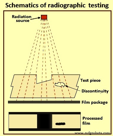
Fig 5 Schematics of radiographic testing
To produce an x-ray or gamma ray radiograph, the film package ((enclosed in a light tight cassette and comprising film and intensifying screens, the latter being required to reduce the exposure time) is placed close to the surface of the subject. The source of radiation is positioned on the other side of the subject some distance away, so that the radiation passes through the subject and on to the film. After the exposure period the film is removed, processed, dried, and then viewed by transmitted light on a special viewer. Different radiographic and photographic accessories are necessary, including such items as radiation monitors, film markers, image quality indicators, dark-room equipment, etc. As far as the last is concerned there are many degrees of sophistication, including fully automatic processing units. These accessories are the same for both x-ray and gamma radiography systems. Also needed are such consumable items as radiographic film and processing chemicals
Recent developments in radiography permit ‘real time’ diagnosis. Such techniques as computerized tomography yield much important information, though these methods can be suitable for only investigative purposes and not generally employed in production quality control.
Industrial radiography involves exposing a test object to penetrating radiation so that the radiation passes through the object being inspected and a recording medium placed against the opposite side of that object. For thinner or less dense materials such as aluminum, electrically generated x-radiations (x-rays) are normally used, and for thicker or denser materials, gamma radiation is generally used. Gamma radiation is given off by decaying radioactive materials, with the two most commonly used sources of gamma radiation being Iridium-192 (Ir-192) and Cobalt-60 (Co-60). Ir-192 is normally used for steel upto 15 mm to 25 mm, depending on the Curie strength of the source, and Co-60 is normally used for thicker materials due to its greater penetrating ability. The recording media can be industrial x-ray film or one of several types of digital radiation detectors. With both, the radiation passing through the test object exposes the media, causing an end effect of having darker areas where more radiation has passed through the part and lighter areas where less radiation has penetrated. If there is a void or defect in the part, more radiation passes through, causing a darker image on the film or detector.
Film radiography uses a film made up of a thin transparent plastic coated with a fine layer of silver bromide on one or both sides of the plastic. When exposed to radiation these crystals undergo a reaction which allows them, when developed, to convert to black metallic silver. This silver is then ‘fixed’ to the plastic during the developing process, and when dried, becomes a finished radiographic film. To be a usable film, the area of interest on the film is to be within a certain density (darkness) range and is to show enough contrast and sensitivity so that discontinuities of interest can be seen. These items are a function of the strength of the radiation, the distance of the source from the film and the thickness of the part being inspected. If any of these parameters are not met, another exposure (is to be made for that area of the part.
Computed radiography is a transitional technology between film and direct digital radiography. This technique uses a reusable, flexible, photo-stimulated phosphor plate which is loaded into a cassette and is exposed in a manner similar to traditional film radiography. The cassette is then placed in a laser reader where it is scanned and translated into a digital image, which take from one to five minutes. The image can then be uploaded to a computer or other electronic media for interpretation and storage. Computed tomography uses a computer to reconstruct an image of a cross sectional plane of an object as opposed to a conventional radiograph. The computed tomography image is developed from multiple views taken at different viewing angles which are reconstructed using a computer. With traditional radiography, the position of internal discontinuities cannot be accurately determined without making exposures from several angles to locate the item by triangulation. With computed tomography, the computer triangulates using every point in the plane as viewed from many different directions.
Digital radiography digitizes the radiation which passes through an object directly into an image which can be displayed on a computer monitor. The three principle technologies used in direct digital imaging are amorphous silicon, charge coupled devices, and complementary metal oxide semi-conductors. These images are available for viewing and analysis in seconds compared to the time needed to scan in computed radiography images. The increased processing speed is a result of the unique construction of the pixels; an arrangement which also allows a superior resolution than is found in computed radiography and most film applications.
The advantages of radiographic testing include (i) is useful on wide variety of materials, (ii) can be used for checking internal mal-structure, misassembly or misalignment, (iii) provides permanent record, and (iv) devices for checking the quality of radiograph are available. Some of the limitations of this method are (i) access to both sides of the object is needed, (ii) cannot detect planar defects readily, (iii) thickness range which can be inspected is limited, (iv) sensitivity of inspection decreases with thickness of the test object, (v) considerable skill is needed for interpretation of the radiographs, (vi) depth of defect is not indicated readily, and (vii) x-rays and gamma rays are hazardous to human health.
Ultrasonic testing
Ultrasonic technique is used for the detection of internal and surface (particularly distant surface) defects in sound conducting materials. The principle is in some respects similar to echo sounding. A short pulse of ultrasound is generated by means of an electric charge applied to a piezo electric crystal, which vibrates for a very short period at a frequency related to the thickness of the crystal. In flaw detection, this frequency is normally in the range of one million to six million times per second (1 MHz to 6 MHz). Vibrations or sound waves at this frequency have the ability to travel a considerable distance in homogeneous elastic material, such as many metals with little reduction. The velocity at which these waves propagate is related to the Young’s Modulus for the material and is characteristic of the material. For example the velocity in steel is 5,900 metres per second, and in water 1,400 metres per second.
Ultrasonic energy is considerably reduced in air, and a beam propagated through a solid, on reaching an interface (e.g. a defect, or intended hole, or the back wall) between that material and air reflects a considerable amount of energy in the direction equal to the angle of incidence. For contact testing the oscillating crystal is incorporated in a hand held probe, which is applied to the surface of the material to be tested. To facilitate the transfer of energy across the small air gap between the crystal and the test piece, a layer of liquid (referred to as ‘couplant’), usually oil, water or grease, is applied to the surface. The crystal does not oscillate continuously but in short pulses, between each of which it is quiescent.
Piezo electric materials not only convert electrical pulses to mechanical oscillations, but also transduce mechanical oscillations into electrical pulses. Hence, there is not only a generator of sound waves but also a detector of returned pulses. The crystal is in a state to detect returned pulses when it is quiescent. The pulse takes a finite time to travel through the material to the interface and to be reflected back to the probe.
The standard method of presenting information in ultrasonic testing is by means of a cathode ray tube, in which horizontal movement of the spot from left to right represents time elapsed. The principle is not greatly different in digitized instruments that have a LCD (liquid crystal display) flat screen. The rate at which the spot moves is such that it gives the appearance of a horizontal line on the screen. The system is synchronized electronically so that at the instant the probe receives its electrical pulse the spot begins to traverse the screen. An upward deflection (peak) of the line on the screen is an indication of this occurrence. This peak is normally termed the initial pulse.
Whilst the base line is perfectly level the crystal is quiescent. Any peaks to the right of the initial pulse indicate that the crystal has received an incoming pulse reflected from one or more interfaces in the material. Since the spot moves at a very even speed across the tube face, and the pulse of ultrasonic waves moves at a very even velocity through the material, it is possible to calibrate the horizontal line on the screen in terms of absolute measurement. The use of a calibration block, which produces a reflection from the back wall a known distance away from the crystal together with variable controls on the flaw detector, allows the screen to be calibrated in units of distance, and hence determination of origins of returned pulses obtained from a test piece.
It is hence possible not only to discover a defect between the surface and the back wall, but also to measure its distance below the surface. It is important that the equipment is properly calibrated and, since it is in itself not able to discriminate between intended boundaries of the object under test and unintended discontinuities, the operator is required to identify the origin of each peak. Further as the pulses form a beam it is also possible to determine the plan position of a flaw. The height of the peak (echo) is roughly proportional to the area of the reflector, though there is on all instruments a control, which can reduce or increase the size of an indication – variable sensitivity in fact. Not only is part of the beam reflected at a material / air interface but also at any junction where there is a velocity change, for example steel / slag interface in a weld.
Probing all faces of a test piece not only discovers the three-dimensional defect and measures its depth, but can also determine its size. Two-dimensional (planar) defects can also be found but, unlike radiography, it is best that the incident beam impinges on the defect as near to right angles to the plane as possible. To achieve this some probes introduce the beam at an angle to the surface. In this manner longitudinal defects in tubes (inner or outer surface) are detected.
Interpretation of the indications on the screen requires a certain amount of skill, particularly when testing with hand held probes. The technique is, however, admirably suited to automatic testing of regular shapes by means of a monitor – an electronic device which fits into the main equipment to provide an electrical signal when an echo occurs in a particular position on the trace. The trigger level of this signal is variable and it can be made to operate a variety of mechanical gates and flaw warnings. Furthermore, improvements in computer technology allow test data and results to be displayed and out-putted in a wide variety of formats.
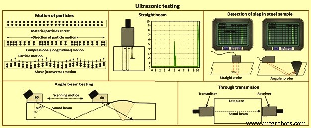
Fig 6 Ultrasonic testing
Modern ultrasonic flaw detectors are fully solid state and can be battery powered, and are robustly built to withstand site conditions. Since the velocity of sound in any material is characteristic of that material, it follows that some materials can be identified by the determination of the velocity. This can be applied, for example in spheroidal graphite cast irons to determine the percentage of graphite nodularity.
When the velocity is constant, as it is in a wide range of steels, the time taken for the pulse to travel through the material is proportional to its thickness. Hence, with a properly calibrated instrument, it is possible to measure thickness from one side with accuracy in hundredths of a millimeter. This technique is now in very common use. A development of the standard flaw detector is the digital wall thickness gauge. This operates on similar principles but gives an indication, in LED (light emitting diode) or LCD 9liquid crystal display) numerics, of thickness in absolute terms of millimetres. These equipments are easy to use but need prudence in their application.
The two most commonly used types of sound waves used in industrial inspections are the compression (longitudinal) wave and the shear (transverse) wave (Fig 6). Compression waves cause the atoms in a part to vibrate back and forth parallel to the sound direction and shear waves cause the atoms to vibrate perpendicularly (from side to side) to the direction of the sound. Shear waves travel at around half the speed of longitudinal waves. Sound is introduced into the part using an ultrasonic transducer (probe) which converts electrical impulses from the ultrasonic testing machine into sound waves, then converts returning sound back into electric impulses which can be displayed as a visual representation on a digital or LCD screen. If the machine is properly calibrated, the operator can determine the distance from the transducer to the reflector, and in many cases, an experienced operator can determine the type of discontinuity which caused the reflector. Because ultrasound does not travel through air (the atoms in air molecules are too far apart to transmit ultrasound), a liquid or gel called ‘couplant’ is used between the face of the transducer and the surface of the part to allow the sound to be transmitted into the part.
Straight beam inspection uses longitudinal waves to interrogate the test piece as shown at the right. If the sound hits an internal reflector, the sound from that reflector reflects to the transducer faster than the sound coming back from the back-wall of the part due to the shorter distance from the transducer. This results in a screen display. Digital thickness testers use the same process, but the output is shown as a digital numeric readout rather than a screen presentation.
Angle beam inspection uses the same type of transducer but it is mounted on an angled wedge (also called a probe) that is designed to transmit the sound beam into the part at a known angle. The most commonly used inspection angles are 45 degrees, 60 degrees, and 70 degrees, with the angle being calculated up from a line drawn through the thickness of the part (not the part surface). A 60 degree probe is shown in Fig 6. If the frequency and wedge angle is not specified by the governing code or specification, it is upto the operator to select a combination which adequately inspects the part being tested. In angle beam inspections, the transducer and wedge combination (also referred to as a probe) is moved back and forth towards the weld so that the sound beam passes through the full volume of the weld. As with straight beam inspections, reflectors aligned more or less perpendicular to the sound beam sends sound back to the transducer and are displayed on the screen.
Immersion Testing is a technique where the part is immersed in a tank of water with the water being used as the coupling medium to allow the sound beam to travel between the transducer and the part. The ultrasonic testing machine is mounted on a movable platform (a bridge) on the side of the tank so it can travel down the length of the tank. The transducer is swivel-mounted on at the bottom of a waterproof tube which can be raised, lowered and moved across the tank. The bridge and tube movement permits the transducer to be moved on the X-, Y- and Z-axes. All directions of travel are gear driven so the transducer can be moved in accurate increments in all directions, and the swivel allows the transducer to be oriented so the sound beam enters the part at the required angle. Round test parts are frequently mounted on powered rollers so that the part can be rotated as the transducer travels down its length, allowing the full circumference to be tested. Multiple transducers can be used at the same time so that multiple scans can be performed.
Through transmission inspections are performed using two transducers, one on each side of the part (Fig 6). The transmitting transducer sends sound through the part and the receiving transducer receives the sound. Reflectors in the part cause a reduction in the amount of sound reaching the receiver so that the screen presentation shows a signal with lower amplitude (screen height).
Phased array inspections are done using a probe with multiple elements which can be individually activated. By varying the time when each element is activated, the resulting sound beam can be steered, and the resulting data can be combined to form a visual image representing a slice through the part being inspected.
Time of flight diffraction uses two transducers located on opposite sides of a weld with the transducers set at a specified distance from each other. One transducer transmits sound waves and the other transducer acting as a receiver. Unlike other angle beam inspections, the transducers are not manipulated back and forth towards the weld, but travel along the length of the weld with the transducers remaining at the same distance from the weld. Two sound waves are generated, one travelling along the part surface between the transducers, and the other travelling down through the weld at an angle then back up to the receiver. When a crack is encountered, some of the sound is diffracted from the tips of the crack, generating a low strength sound wave which can be picked up by the receiving unit. By amplifying and running these signals through a computer, defect size and location can be determined with much greater accuracy than by conventional ultrasonic testing methods.
The advantages of ultrasonic flaw detection include (i) thickness and lengths upto 10 meter can be tested, (ii) position, size and type of defect can be determined, (iii) instant test results, (iv) portable, (v) extremely sensitive if required, (vi) capable of being fully automated, (vi) access to only one side necessary, and (vii) no consumables needed. The disadvantages of ultrasonic flaw detection include (i) no permanent record available unless one of the more sophisticated test results and data collection systems is used, (ii) the operator can decide whether the test piece is defective or not whilst the test is in progress, (iii) indications need interpretation, (iv) considerable degree of skill
製造プロセス