


NEMA モーター。よくある問題
FFF 3D プリンターの基本コンポーネントの 1 つはモーターです。それらは、プリント ヘッドを配置するために必要な動作を行うことと、エクストルーダーでフィラメントを引っ張ることを担当します。
使用されるモーターはステッピング モーターで、最も一般的なタイプは NEMA 17 と NEMA 23 です。
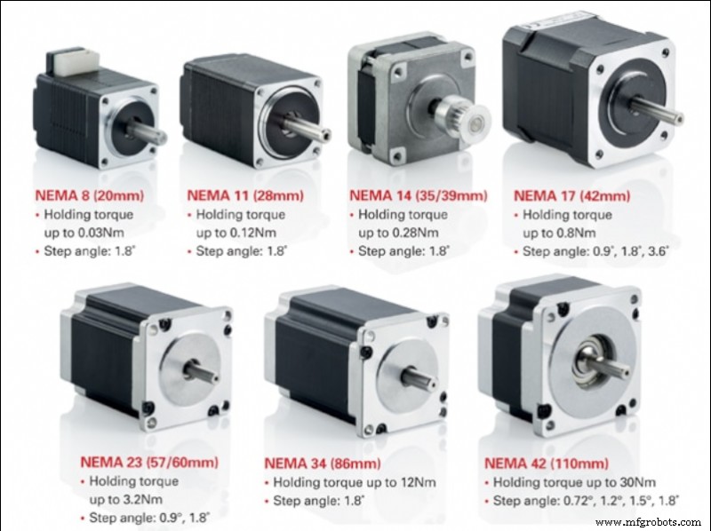
画像 1:NEMA モーターの種類。出典:motioncontrolproducts.com
高品質のステッピング モーターは非常に高い信頼性を備えているため、モーターの故障の主な原因は通常、外部にあり、通常はパワー ドライバーまたは接続に関連しています。
ステッピング モーター
ステッピングモーターは、連続的に回転するモーターの一種です。回転は、特定の角度の個別のジャンプで発生します。標準のDCモーターとサーボモーターの中間のモーターです。 DC モーターのように、複数の 360 ° 回転が可能であり、サーボ モーターのように正確な角度位置決めが可能です。
3D プリンターで最も一般的に使用されるのはバイポーラ ハイブリッド ステッピング モーターで、通常は NEMA17 または NEMA23 形式です。ハイブリッド モーターは、VR モーターの小型ステッパー機能と永久磁石モーターの高慣性機能を組み合わせたものです。一方、バイポーラ モーターは、ユニポーラ モーターよりもトルクと固定力が高く、軽量でサイズも小さいですが、特定のパワー コントローラーが必要です。
ステッピング モーターを選択するときは、その主な特性を知っておく必要があります。
- ステップ: これは、モーターが (マイクロステップ コントローラーを使用せずに) 直接回転できる最小角度です。通常、1.8 º または 0.9 º のステップを持つモーターを見つけることができます。一般に、ステップが小さいほど精度が高くなりますが、最大回転速度も低くなります。
- 作業電流: これは、モーターが適切に動作するためにモーターに供給しなければならない最大電流値です。モーターに印加する電流が多いほど、達成されるトルクが大きくなるため、ステップを失うことなく大きな慣性に耐えることができますが、発熱と摩耗も大きくなります。メーカーが指定した値よりも高い電流を使用すると、モーターの劣化や故障の原因となります。
- 1 相あたりの電圧: これは、各コイルが正しく動作するために必要な電圧です。
- 位相抵抗: これは、各コイルによって提供される電気抵抗です。
- 相インダクタンス: 起動時に各コイルによって生成される最大インダクタンス値。
- 測位精度: 回転運動中に発生する可能性のある最大偏差。一般に、値が小さいほど精度が高いことを表します。
- 最高動作温度: これは、モーターが耐えることができる最大動作温度です。この温度を長時間超えると、モーターの故障につながります。
- ローター慣性: これは、ローターが空のときに自重によって提供される慣性です。モーターによってサポートされる慣性は、これにモーターに結合された要素の慣性を加えたものになります。
- トルクまたは保持トルク: これは、フェーズが非アクティブ (電流なし) のときに、モーターがシャフトを回転させずに耐えることができる最大トルクです。
- アンカー トルク: これは、モーターが停止し、フェーズがアクティブ (ライブ) のときに、シャフトを回転させずにモーターが耐えることができる最大トルクです。この値は、最大電流が供給されるモーターに対して考慮されます。
- 始動トルク: これは、ローターの慣性を克服して回転を開始するために必要なトルクです。
- 回転トルク: これは、モーターが回転中にステップロスを起こさずに耐えることができる最大トルクです。この値は、最大電流が供給されるモーターに対して考慮されます。
XY 軸の場合など、高速で動作し、移動中に高い慣性に耐えることができるモーターを探している場合は、1.8 º ステップで高トルクのモーターを選択する必要があります。
Z 軸モーターは高い作業速度を必要としないため、0.9 º モーターを使用するとよりスムーズな動きが得られます。この場合、プラットフォームまたはガントリーの重量を支えるために、最大の保持および固定トルクを持つモーターを選択する必要があります (プリンターの設計によって異なります)。
バイポーラ ステッピング モーターの接続
ステッピング モーターを正しく接続するときは、ワイヤーの位置がモデルによって異なるため、メーカーの仕様書を用意しておくと便利です。
通常、バイポーラ ステッピング モーターには、2 つの独立した電源回路からなる 4 つの接続があります。各回路は、モーターの各コイルに電力を供給する正極と負極で構成されています。
最初に知っておくべきことは、プリンター制御ボード上のこれら 4 つの接続の位置です。制御盤には 2 種類の命名法があります。 1 つ目は 1A 1B 2A 2B で、各数字は回路を表し、文字 A と B は極を表します。 2つ目はA A - B B - ここで、各文字は回路を表し、アクセントは負極を表します。
ボード上の接続が決定されたら、モーターに対しても同じことを行う必要があります。
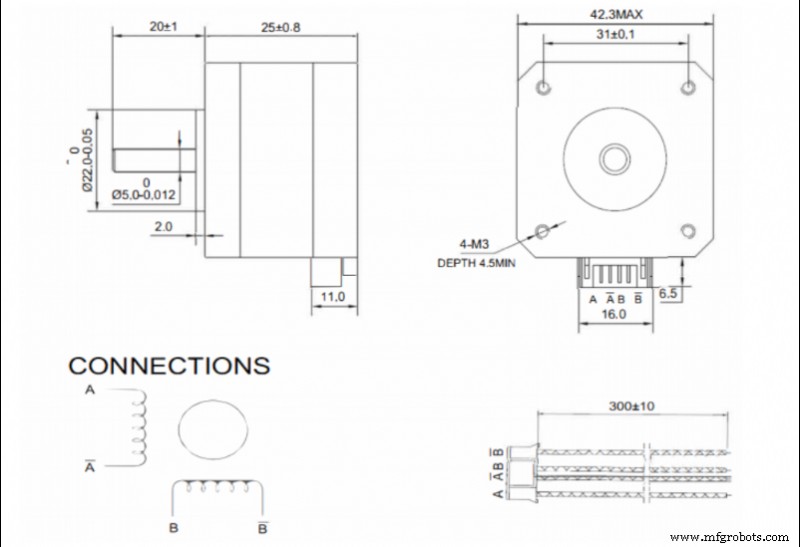
画像 2. NEMA17 モーター仕様書の接続例。出典:ボンドテック
仕様書が入手できる場合は、コネクタ内のワイヤの順序を参照する必要があります。この場合、命名法 A A - B B - が最も一般的です。
基板とモーターの呼び名が同じ場合は、各端子をペアリングするだけで簡単に接続できます。異なる命名法を使用する場合は、次のようにペアにする必要があります:
- 1A - A
- 1B - A -
- 2A - B
- 2B - B -
モーターのデータシートが入手できない場合は、各スプールの接続ペアを決定する必要があります。これは、コネクタ ピン ペアのすべての可能な組み合わせで抵抗を測定することによって行われます。抵抗が無限でない場合、最初のペアが配置されています。モーター メーカーが使用する最も一般的な組み合わせは 1-3 4-6 または 1-4 3-6 であるため、これら 2 つの組み合わせをテストすることから始めてください。
位置が特定されると、各フェーズが各スプールに接続されます。 2つの相が同じ極性でコイルに接続されていることが重要です。そのため、それらを逆相に配置すると、モーターに電流を流したときに動かず、ノイズが発生します。この場合、コイルの 1 つの極性を逆にする必要があります。
両方のフェーズを分離しておくことが非常に重要であるため、コネクタの状態を頻繁にチェックする必要があります。相間の接触不良またはブリッジは、モーターの動作を停止させます。
モーター電流の設定
ステッピング モーターは、特定のコントローラーまたはドライバーを介して電力を供給されます。市場には多くの異なるモデルがあります。一般に、高品質のものは耐久性が高く、操作音が静かです。
利用可能なモデルには、モーターに送られる電流を調整する方法が 2 つあります。
- 調整ネジによる。 一般に、低品質または安価なドライバーでは、ネジの形をしたポテンショメーターを使用して出力電流を調整できます。 In this case it is necessary to use a multimeter and a precision ceramic screwdriver to make the adjustment.
In this case the adjustment can be made in two ways:
- By Current:With the printer switched on and the motors connected, the current in one of the phases will be measured and adjusted to the appropriate value. This method is not recommended, especially the first time a new driver is connected, as the motors are initially powered without knowing if the output current is higher than the current admitted by the motor.
- By reference voltage:This is a slightly more complex method, but more recommendable. First we must determine the required reference voltage using the formula:
max · 8 · Rs
Where Imax is the maximum current at which the motor will be powered (usually at most 90 % of the maximum specified by the manufacturer) and Rs is the detection resistance of the driver.
To adjust it on the driver, simply power up the driver, measure the voltage between the Vref pin (usually the potentiometer itself) and a ground pin (usually the power supply pin) and set the appropriate value using the potentiometer.
- By firmware: Many current drivers do not have an adjustment potentiometer and allow the output current to be set directly by firmware. To do this, simply set the appropriate current value in the motor section of the firmware.
When selecting the output current of the drivers, it is not advisable to use the maximum value determined by the manufacturer. In order to prolong the service life of the motors, do not exceed 90 % of the manufacturer's maximum value, the optimum being the minimum current required to generate sufficient torque to withstand the inertias.
Higher current, in addition to higher torque, also means higher heating, higher motor noise and higher wear.
Maximum speed of a stepper motor
Stepper motors advance by pulses, so the maximum speed of the motor will depend on the maximum signal frequency that the control board is able to send. In addition, it must be taken into account that usually several motors are working simultaneously, so the frequency for each one will decrease.
For example, if the control board works at 100000 Hz and 4 motors (X,Y,Z and extruder) are working simultaneously, each motor will be controlled at 25000 Hz, or 25000 pulses per second. This means that a 1.9 ° motor without microstepping can rotate at a maximum of 125 rps. In a GT2 8-tooth belt drive system (the most common) this translates into a theoretical maximum linear speed of 3600 mm/s.
In the case of microstepping, the maximum speed would be reduced proportionally, so that if 16 microsteps are used, the maximum speed would be 225 mm/s, but if 256 microsteps are used, it would be reduced to only 14 mm/s.
It is very important to know the operating frequency of the control board, as the combination of a low output frequency with a high microstep setting can cause the maximum allowable speed to be lower than the printing speed, resulting in a significant loss of steps.
Appropriate setting of the steps per mm
When the motion signal is transmitted to the motor, it is sent as a rotation, however the movements included in the print files are linear. This is why the printer must be able to translate the angular movement into a linear one.
The movement is generally transmitted by means of toothed pulleys and belts, so that the step/mm conversion depends on the diameter of the pulleys.
To calculate this, the following formula is simply applied:
steps/mm = (360/P) · MS
2 · π · Rpulley
Where P is the motor pitch, MS the configured microsteps (1 in case of not using microstepping) and Rpulley the radius of the pulley used.
In the case of screw-transmitted movements, it is the pitch of the screw that defines the feed rate. For this purpose, the following formula is simply applied:
steps/mm = (360/P) · MS
A
Where P is the motor pitch, MS the configured microsteps (1 in case of not using microstepping) and A the pitch of the screw thread.
There are also many calculators that make it easier to obtain these values, such as the one offered by Prusa Printers.
Once these values have been obtained, and although in theory they are correct, it is advisable to carry out a precise calibration to compensate for possible manufacturing or assembly defects.
For this purpose, a cube of known dimensions (e.g. 50 x 50 x 50 mm) shall be printed out and the actual dimensions measured. Once this is done, the following formula shall be applied:
steps/mm = Dtheorical · Pactual
Dreal
where Dtheorical is the theoretical size that the part should have, Pactual is the current P/mm setting and Dreal is the measurement value obtained from the printed part.
By introducing the new P/mm value, you should obtain parts with appropriate dimensions.
Considerations to take into account
- Step loss: A step loss is usually caused by excessive torque in the engine. Large accelerations or high direction change speeds will cause inertias that the motor torque cannot compensate for, resulting in a step loss. Similarly, the combination of low signal frequencies and high microstep settings will drastically reduce the maximum motor speed. If the print speed exceeds this, a step loss will also occur. In any case, step loss in an open-loop printer will result in loss of position.
- Temperature: A high current setting will cause the motor to heat up. If the motor is inside a closed or heated structure that does not allow the heat to dissipate correctly, the working temperature may be exceeded, causing the demagnetisation of the magnets and a malfunction or breakdown of the motor. In closed printers, it is advisable to place the motors outside the chamber or, if this is not possible, to reduce the current to the minimum necessary.
- Hysteresis: This is a phenomenon intrinsic to motors. It can cause a small position error at the end of a movement. Using quality motors will reduce this error.
- Resonance: All motors have a natural frequency. If the pulse frequency sent to the motor is similar to the natural frequency, a resonance effect will occur. This will cause increased vibration, noise and wear.
- Step settings: Improper step/mm settings will result in positioning error, which will be reflected in dimensional errors in the parts.
- Connection: Mixing or bridging phases will cause the motor to not turn or to turn erratically. Placing one phase with the polarity reversed with respect to the other will cause the motor not to turn. Reversing the polarity of both phases, when connected correctly, will cause the motor to rotate in the opposite direction.
This guide discusses concepts in a general way and does not focus on a particular make or model, although they may be mentioned at some point. There may be important differences in calibration or adjustment procedures between different makes and models, so it is recommended that the manufacturer's manual be consulted before reading this guide.
3Dプリント