


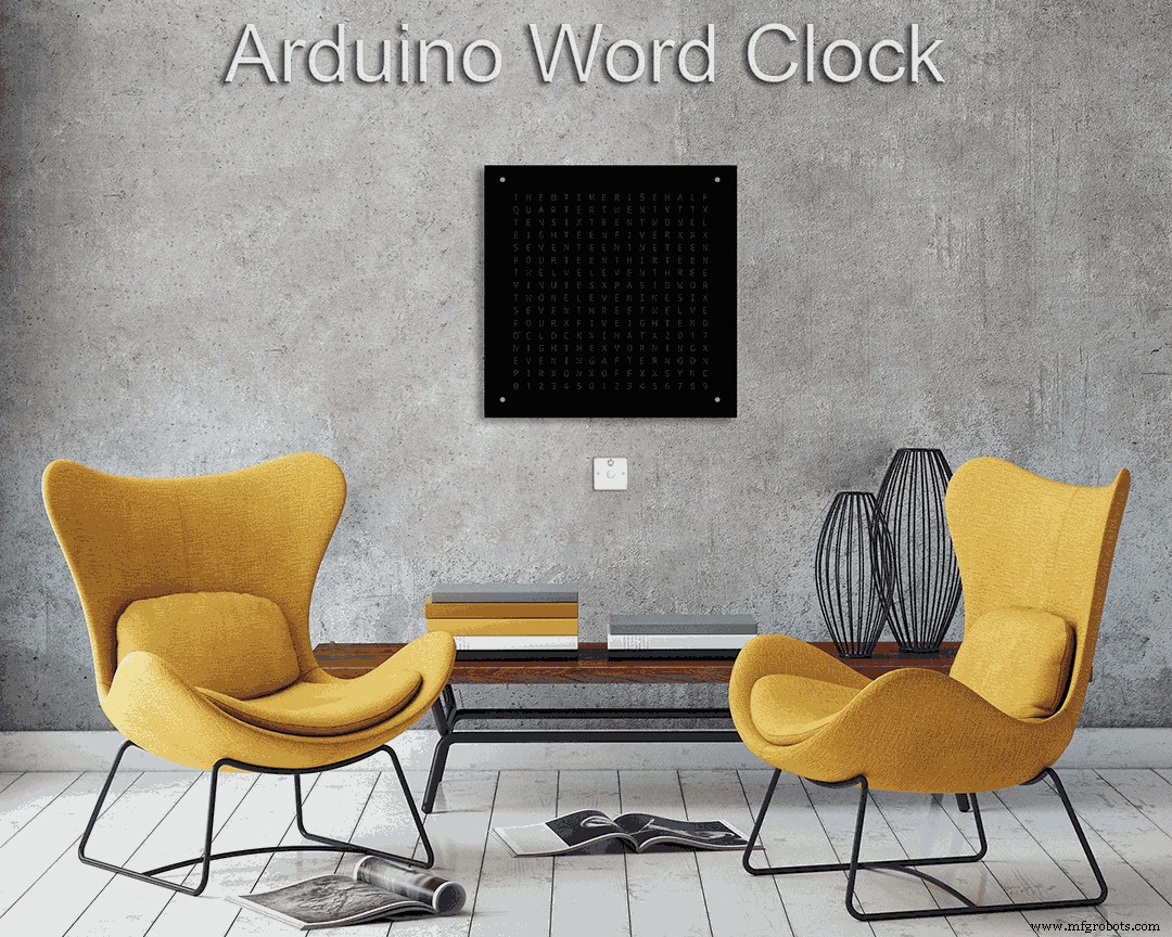
単語単位の時間の分分解能を備えた世界時計
コンポーネントと消耗品
>  |
| × | 1 |
このプロジェクトについて
このビルドの詳細については、私のサイトのWord Clock
を参照してください。時間の分単位の解像度と秒の線形表示を備えたArduinoワードクロック。
<図>
デジタル時計、アナログ時計、温度と湿度のモードのほか、ライフゲーム、サイモン、テトリスの3つのゲームもあります。
クロックはスタンドアロンにすることも、必要に応じてマスタークロックからスレーブとして実行することもできます。
マスタークロックがない場合、時間はワードクロックに組み込まれている温度補償されたリアルサイムクロックによって制御されます。
PIRまたはドップラーレーダー制御のオプションがあるため、部屋に誰もいないときに時計が自動的にオフになります。
時計のサイズは500mmx 500mm(19.68 "x19.68")、重さは12lb(5.5Kg)で、壁に取り付けるように設計されています。時計を設定および制御するためのタッチパッドが各コーナーにあります。
ステップ1:ワードクロックについて
ワードクロックについて
ワードクロックは、単語または数字と文字のマトリックスを使用して時刻を示し、長年にわたって使用されてきました。クロックビルドの複雑さに影響を与えるいくつかの異なるデザインタイプがあります。
<図>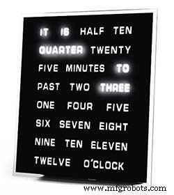
最も単純な単語のブロックを使用して、5分の解像度で時刻を示します(例:O'CLOCK、5 PAST、10 PASTなど)。これらの時計は、20個程度の個別のLEDブロックのみを使用するため、構築が最も簡単です。これらの時計の主な欠点は、この設定された形式でしか時刻を表示できないことです。
<図>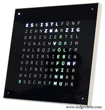
中レベルの時計には、11x10のLEDマトリックスと時計の外側に4つの追加LEDがあります。RaspberryPi制御時計写真2にはマルチカラーLEDもあり、110個の個別のLEDがあるため、数字と基本的な画像を表示できます。これらの時計は、言葉で5分の解像度を使用しますが、解像度をわずかに上げるために「5を過ぎた」または「ほぼ10に」を追加することがよくあります。多くの場合、フレームの隅にある4つのLEDは、間のギャップを埋めるために4分が経過したことを示します。 5分の言葉による解像度。これらの時計は構築がかなり複雑で、多くの場合、構築を容易にするためにLEDのストリップを使用します。
<図>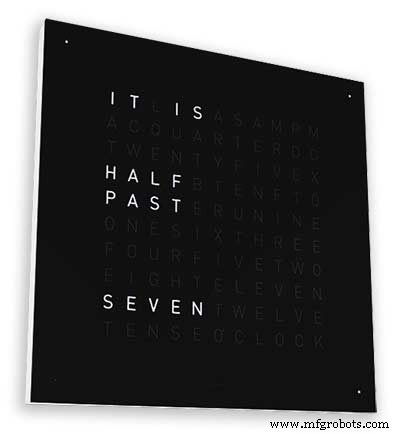
このタイプの時計の商用バージョンが利用可能です。450mmの壁掛けバージョンは約1,000ポンドで、さまざまな色と素材の交換可能なフロントパネルと、小型のデスクトップと時計が利用できます。
<図>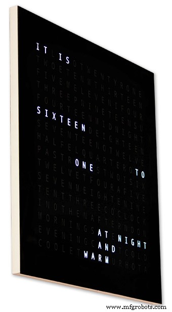
WouterDevinckによる256マトリックスワードクロック
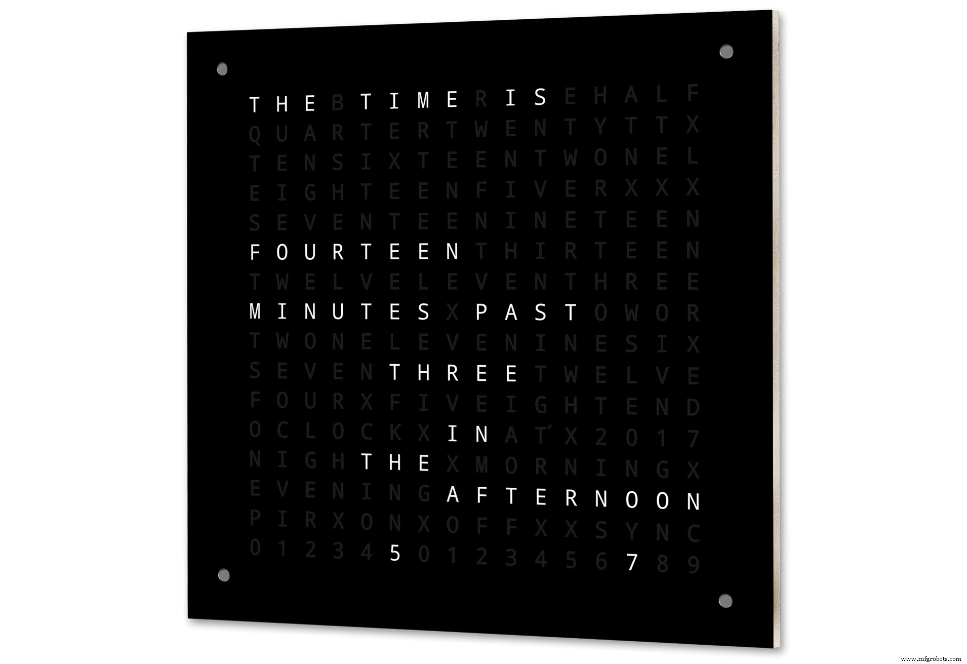
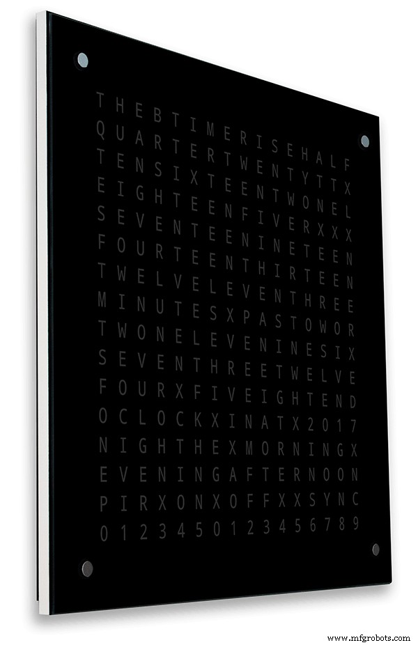
最高レベルの複雑さを備えたワードクロックは、16x16 LEDマトリックスを使用して、完全な256個のLEDを制御します。これらのクロックは、朝、夕方、夜などと同様に、1分間の時間のワード解像度を備えています。暖かい、非常に暖かい、冷たい非常に冷たいなどのように。
256個のLEDを使用して、さまざまな表示モードを利用できます。これらのクロックは、マトリックスディスプレイの接続数が多いため、作成が非常に複雑です。表面実装コンポーネントを備えたPCB上にLEDマトリックスを構築すると、非常にスリムな時計本体が可能になり、ディスプレイの構造が簡単になりますが、500mm x500mmを超えるとPCBは高価になり始めます。
私の時計のようにLEDマトリックスを手作業で作成するにはスペースが必要であり、500mm x 500mmは、LEDとディスプレイモジュールを相互接続するために必要な大きなワイヤーハーネスにほぼ対応できるため、出発点として適しています。非常に大きな壁掛け時計は、手作りのLEDマトリックスを使用して作成できます。
ステップ2:変更 <図>
変更点
この時計は、Wouter DevinckClockハードウェアと「Catalan」Pijuana時計ソフトウェアを組み合わせたものです。既製のモジュールと3つの小さなVeroボード回路を電源に使用したことはありません。
主な変更点は以下のとおりです。
このバージョンのクロックではカスタムPCBは使用されておらず、ビルド済みのモジュールで簡単に入手できます。
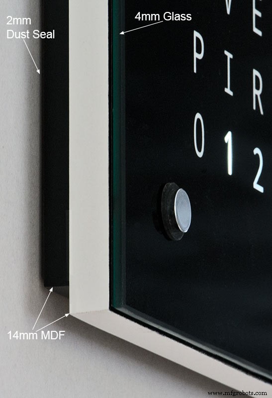
時計本体は、18mmのシート1枚ではなく、14mmのMDF2枚で作られています。
<図>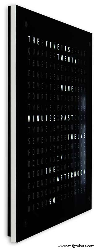
リアシートは、トップを除くすべての面でフロントシートよりも10mm小さいため、時計の厚さはわずか14mmに見えます。
Wouter Devinckの時計は、2mmのガラスを含めてわずか20mmの深さですが、私の時計は、実際には、背面の4mmのガラスと2mmのダストシールを含めて34mmの深さです。後部の14mmパネルのセットバックとほとんどの角度からのガラスパネルの1.5mmセットバックのために、時計は14mmの深さしか見えません。この余分な深さにより、4つの大きなPCBではなく、手作りのLEDマトリックスとワイヤーハーネスを使用できるようになりました。また、MAX7219ボードに表面実装ICがなくても、事前に構築されたメンテナンスが容易なモジュールを使用できることも意味します。
メインディスプレイはPCBなしでディスプレイLEDに直接組み込まれているため、任意のサイズのディスプレイが可能です。メインボードに取り付けられたAzoteq IQS127Dの代わりに、TTP223タッチセンサーモジュールが使用されます。
MAX7219 I / Cのディスプレイドライバボードは、変更されたLEDマトリックスボードを使用します。これらのボードにはすべてのコンポーネントが付属しています。
Arduino Nanoはサイズが小さいため、時計の駆動に使用されます。
PIRセンサーモジュールは、部屋に誰もいないときにディスプレイをシャットダウンするために使用されます(これを無効にすると、ディスプレイを常にオンに保つことができます)。
トリマ抵抗が回路に追加され、時計の下部から小さなマイナスドライバーでアクセスして、自動ディスプレイの明るさを調整します。
30秒に毎分マスタークロックシステムに同期します。同期パルスが利用できない場合、クロックはRTCを使用してフリーランします。同期パルスがメインディスプレイに表示されます。
ソフトウェアは主に単語時計の「カタロニア語」ピファナバージョンに基づいているため、これは表示用に英語に翻訳されています。クレジット表示は、「カタロニア語」ピファナバージョンから変更され、現在のソフトウェアバージョン番号、私の名前、およびビルドの年が表示されます。
ワード温度は時計表示から削除され、線形秒表示がワード、デジタル、アナログ時計の最下行に追加されました。
PIRをオンまたはオフにすると、ワードクロックディスプレイに「PIRON」または「PIROFF」が数秒間表示されます。
このクロックは、Wouter Devinckクロックと「Catalan」ピファナクロックに従って、DS3231 AT24C32I2C高精度リアルタイムクロックモジュールを使用します。モジュールに付属しているリチウムイオン二次電池の使用には熱心ではありません。非充電式バッテリーを使用しており、それに合わせてモジュールを変更しました。
磨かれたエッジを持つ4mmフロートガラスが2mmガラスに取って代わります。ガラスは接着剤ではなくシカゴファスナーを使用してメインMDFボードに固定されています。これらは、時計を制御するためのタッチパッドとしても機能し、必要に応じてガラスを取り外すことができます。
時計には2つのダストシールが組み込まれています。1つは背面パネルに、もう1つは取り外し可能なガラスディスプレイパネルの後ろにあります。時計設定モードでBOT右ボタンを押すと、秒が0にリセットされます。
私が言うように、英語の言い回しに次の変更が加えられました。住んでいる場所や学校に行った場所などによって、地域ごとに時間の言い方が異なります。自分に合った正しい方法はありません。
ワードクロックの温度を示す単語を削除しました。これらは、同期ステータス、PIR ON / OFF、秒の線形表示に置き換えられました。
1分過ぎと1分から1時間に「MINUTES」を「MINUTE」に変更しました。
過去の「QUARTER」の前に「A」を追加し、時間に「QUARTER」を追加しました。
彼のメモに従って、WouterDevinck時計から欠落している「ELEVEN」を追加しました。
正午に、午後にTWELVEOCLOCKを読む時間を変更しました。
真夜中に、夜にTWELVE OCLOCKを読む時間を変更しました。真夜中を過ぎると、時計は常に朝になります。
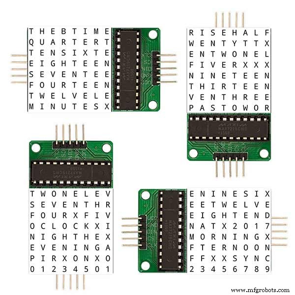
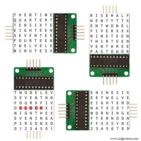
「O'CLOCK」は句読点がなくなり、OCLOCKのみが表示されます。
ステップ3:ケースデザイン <図>
私の時計は表面実装コンポーネントを備えたカスタムディスプレイマトリックスPCBを使用していないため、時計ケースはWouterの設計よりもいくらか深くする必要があります。
私のケースは34mmの深さで、リアダストシール2mm、リアMDFボード14mm、フロントディスプレイボード14mm、4mmフロートガラスが含まれています。
Wouterの右のケースは、深さ21mm、シングルMDFパネル18mm、フロートガラス2mmです。
<図>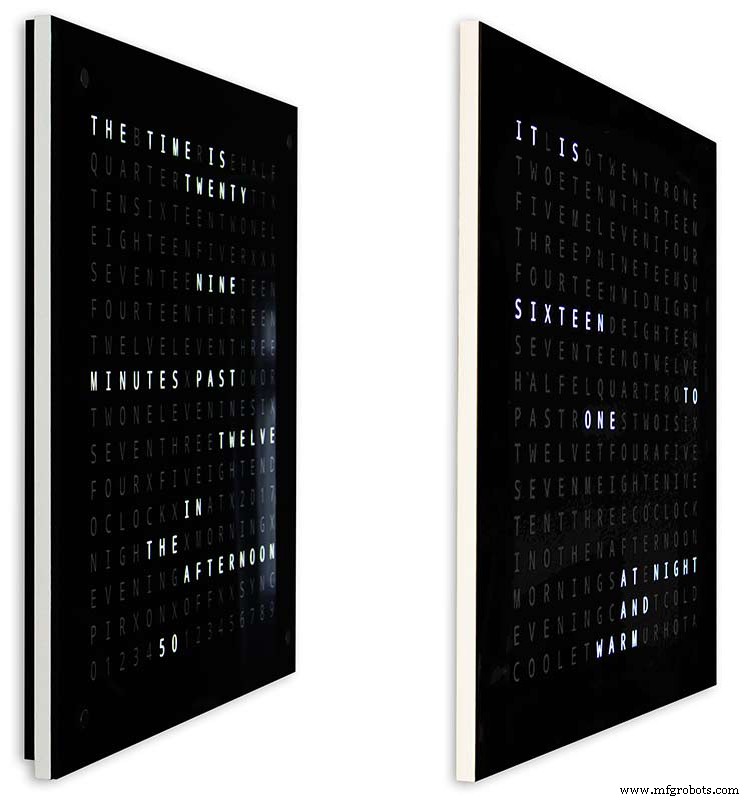
壁に取り付けたときに時計が見た目にかさばらないようにするために、いくつかのシンプルなデザイン機能を取り入れました。上の写真は、左側に私の時計、右側にWouterの時計を示しています。極端な側面から見ると、私のケースがかさばっているように見えることがはっきりとわかります。
これは、リアボードが白ではなく黒であるため、14mmのスリムな白いエッジに目を集中させることで多少相殺されます。リアボードの底面と両側が10mm短くなっているため、このような錯覚が生じます。
<図>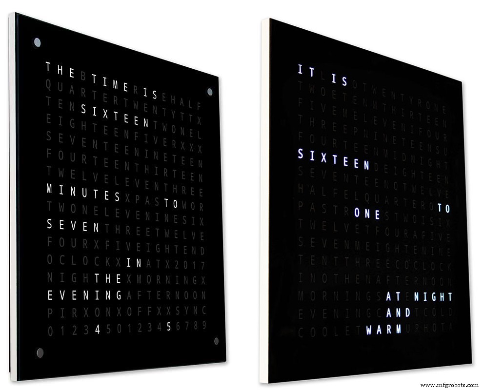
上-再び左側に私の時計、右側にウーターの時計。時計の前に行くほど、時計の短いリアボードが見えなくなり、14mmのスリムなフロントボードだけが見えるようになります.4mmのガラスもフロントボードより1〜2mm短くカットされており、見えないようになっています。 。私のかさばる34mmの時計ケースは、今ではWouterのケースと同じくらいスリムに見えます。
ステップ4:コントロール
コントロール
<図>
時計の左上隅、右上隅、左下隅、右下隅にTTP223タッチコントロールモジュールがあります。
<図>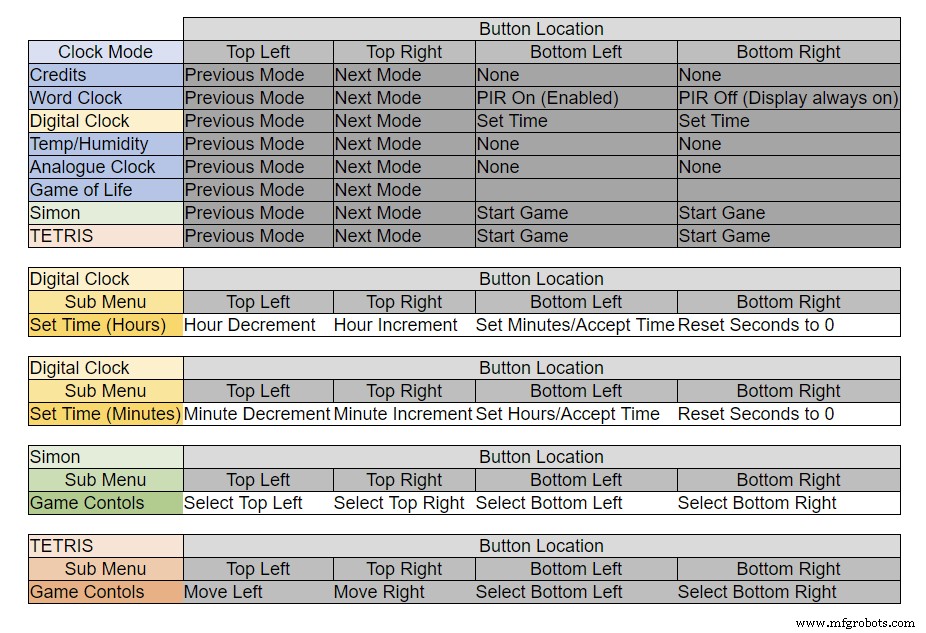
ボタンの機能は、時計のモードによって異なります。上の表を参照してください。
ステップ5:夏と冬の自動設定
使用されていません。
ステップ6:表示モード時計と環境 <図>
<図>
上記のアニメーション1は、4つのクロックモードと環境モードを示しています。
モードは、ワードクロック、デジタルクロック、温度と湿度、アナログクロックの順です。
<図>
上記のアニメーション2。ソフトウェアのバージョン番号、メーカー名、時計の名前をスクロールするスタートアップモードもあります。
ステップ7:表示モードゲーム
3つの古典的なゲームが時計にコード化されています。カタロニアの時計のコードをそのまま残しました。
<図>
コンウェイのライフゲームの上のアニメーション1。 Game of Lifeの宇宙は、正方形のセルの無限の2次元直交グリッドであり、それぞれが生きているか死んでいるか、「人口が多い」または「人口が少ない」という2つの可能な状態のいずれかにあります。
すべてのセルは、水平、垂直、または対角線上に隣接するセルである8つの隣接セルと相互作用します。時間の各ステップで、次の遷移が発生します。2つ未満のライブネイバーを持つライブセルは、過少人口が原因であるかのように死にます。 2つまたは3つの生きている隣人がいる生きている細胞は、次の世代に生き続けます。人口過多のように、3つ以上の生きている隣人がいる生きている細胞は死にます。ちょうど3つの生きている隣接細胞を持つ死んだ細胞は、生殖のように生きた細胞になります。
初期パターンは、システムのシードを構成します。第1世代は、シードの誕生と死のすべてのセルに上記のルールを同時に適用することによって作成されます。これが発生する離散モーメントは、ダニと呼ばれることもあります(つまり、各世代は前の世代の純粋関数です。 1)。ルールは、次の世代を作成するために繰り返し適用され続けます。
<図>
サイモンの上のアニメーション2
サイモンメモリゲーム-コンピュータで生成されたシーケンスをコピーしてみてください。シーケンスを入力するときは、最後のエントリをダブルタップしてターンを終了します。
失敗すると、スコアが画面に表示されます。
<図>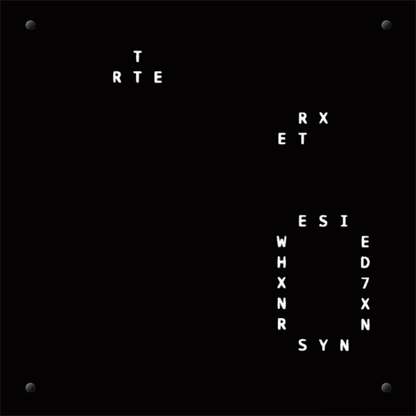
TetrisTetrisの上のアニメーション3は、1984年6月にリリースされたソビエトのタイルマッチングパズルビデオゲームです。このゲームでは、タイルを正しく制御するためにボタンの作業が必要です。
ステップ8:プロトタイピング
クロックは、MAX7219ディスプレイボードの元のDOTマトリックスLEDを使用して、プロトタイプを作成してテストできます。
この一時的な変更は、MAX7219モジュールに付属のDOTマトリックスディスプレイでコードをテストする場合にのみ必要であることに注意してください。
これは、フルサイズバージョンにコミットする前に、ソフトウェア/ワードレイアウトの変更をミニチュアで試すことができることを意味します。 DOTマトリックスLEDへの配線は、ソフトウェア接続に一致するように変更する必要があります。
<図>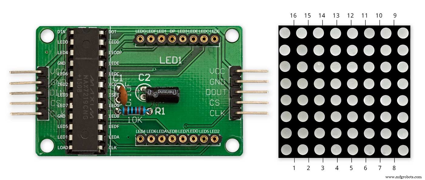
上の写真は、モジュールが変更前にどのように配線されているかを示しています。変更は非常に簡単です。まず、次のLEDマトリックスピンを90°曲げ、上部のピンを上に、下部のピンを下に曲げます。
ピン16、15、3、4、10、11。
LEDマトリックスをディスプレイPCBのソケットに挿入すると、上記のピンは接続されなくなります。ディスプレイPCBのソケットの背面から突き出ているLEDマトリックスピンに次のリンクワイヤーをはんだ付けします。
LEDAからドットマトリックスピン16へ
LEDBからドットマトリックスピン15へ
LEDGからドットマトリックスピン3
LEDFからドットマトリックスピン4へ
LEDEからドットマトリックスピン10
LEDCからドットマトリックスピン11
<図>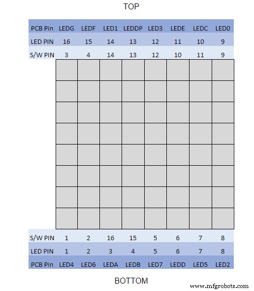
マルチメータを使用して、ディスプレイモジュールをバズアウトしました。この表は、ソフトウェアのピン番号がディスプレイボードのLEDのピン番号と異なるところを示しています。
<図>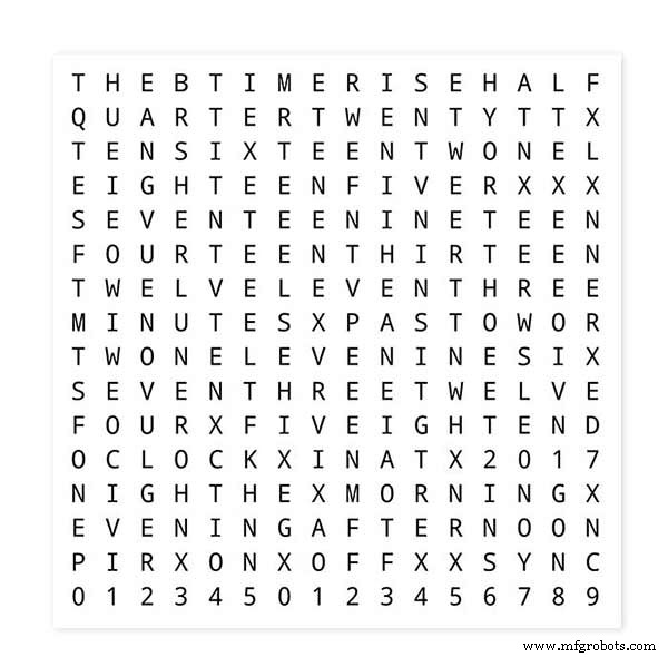
単語のレイアウトをテストするには、単語表示のミニチュアバージョンを62mm x62mmの白い紙に印刷します。
<図>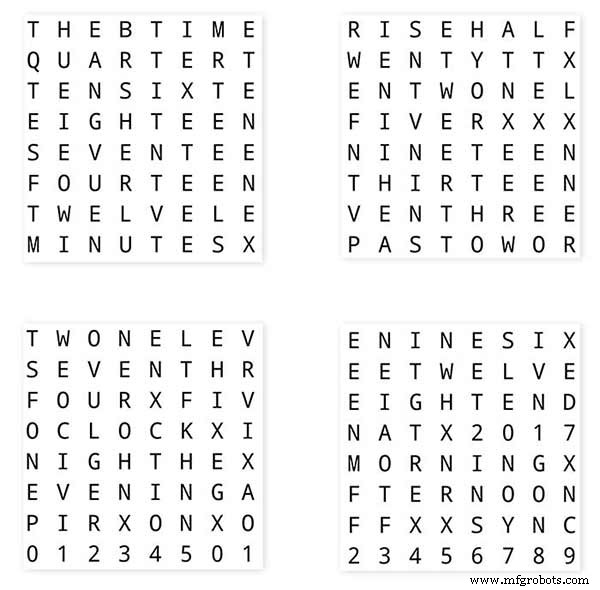
<図>
<図>
ソフトウェアのレイアウトに合わせて、LEDディスプレイボードの向きに注意してください。
誰かが私の時計にWouterDevinck PCBデザインを使用する場合に備えて、ディスプレイの回転を元のWouterDevinck時計として維持しました。
<図>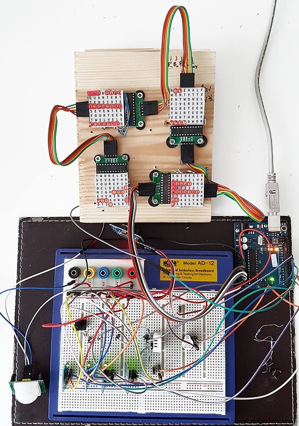
温度/湿度センサーの下にある小さな押しボタンは、30秒の同期をテストするために使用されます。タッチボタンモジュールは、横向きに取り付けられたブレッドボードの左下にあります。ほとんどの配線はディスプレイマトリックスにあるため、このプロトタイプには多くの配線はありません。最終時計では、この配線は個々のLEDに手動で行われます。
最終的な時計を作成する前に、このボードでさまざまな単語/時計のデザインを試しました。
ステップ9:変更されたモジュールのテスト <図>
配線変更後にMAX2719モジュールをテストできるように、ワードクロックスケッチを変更しました。
このプログラムはすべて、マトリックスの左上から右下に向かって各LEDを順番に点灯します。
5本のワイヤーをNANOおよびMAX2719モジュールに接続し、USBポートからNANOに電力を供給するだけです。スケッチをロードして実行します。
<図>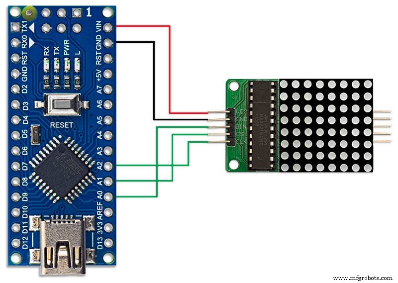
各モジュールを順番に差し込むだけで、配線を確認できます。
同封のzipファイルからテストスケッチをダウンロードします。
MAX7219_LED_Test.zip
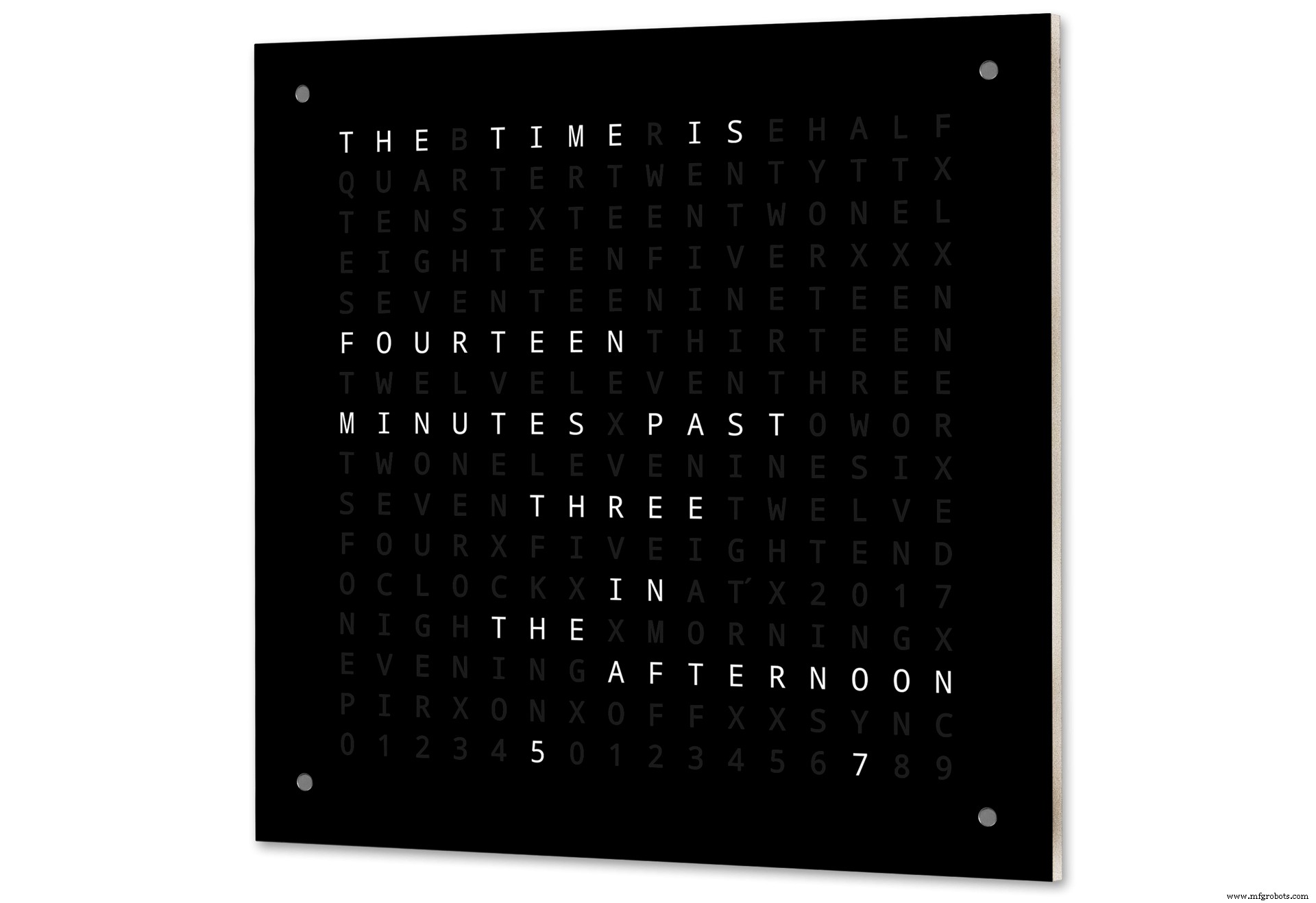
ステップ10:単語マッピングまでの時間 <図>
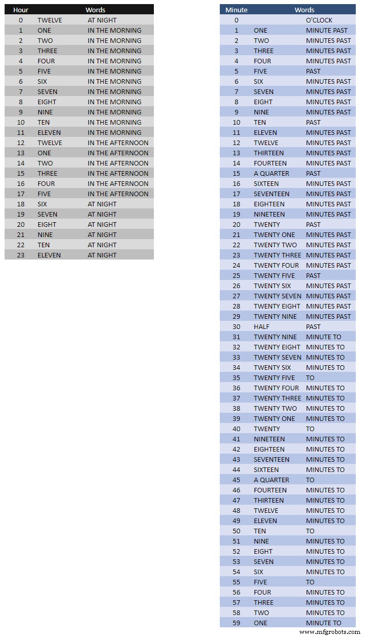
上の表は、単語マッピングまでの時間を示しています。
あなたが時間を言うように、これらにはただ言葉を設定するだけの厳格な規則はありません。
私の時計では、Wouterの時計の言葉と比較して次のように変更しました。
「MINUTES」は、1分過ぎと1分から1時間に「MINUTE」に変更されました。過去の「QUARTER」の前に「A」を追加し、時間に「QUARTER」を追加しました。
正午に、午後にTWELVEOCLOCKを読む時間を変更しました。
真夜中に、夜にTWELVE OCLOCKを読む時間を変更しました。
真夜中を過ぎると、時計は常に朝になります。
これらの変更は、時計ソフトウェアに非常に簡単に実装できます。
Word%2Bto%2BTime%2BTranslations.xlsx
ステップ11:電源 <図>
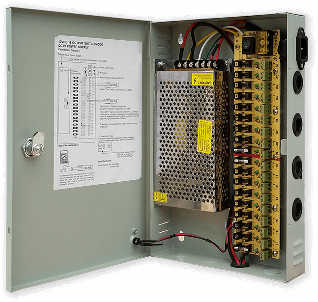
私は一般的な12ボルトの電源ユニットを使用して、家中のさまざまな種類の回路を駆動しています。次に、この12ボルトの電源は、5ボルトのモジュールを使用して各回路でローカルに降圧され、制御ボードとさまざまなモジュールに電力を供給します。
私の一般的な電源には、それぞれ2Aのヒューズが付いた18個の個別にヒューズされた12v回路があります。これらのうち9つはバッテリーでバックアップされています。クロックボードにも独自のオンボードヒューズがあります。
この1つの回路だけを実行している場合は、回路で使用する電流を供給できる限り、安定化された5ボルトの電源で十分です。
<図>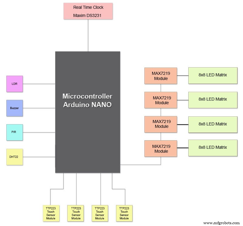
MP1584ミニチュア電源を使用する電源ボードをVeroで設計しました。これにより、共通電源からの12v出力がクロック用の5vに変換されます。
<図>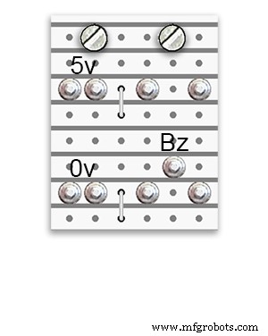 <図>
<図> 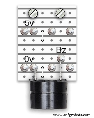
Veroボードから構築された2つの追加のパワーボードがあります。
ブザーを保持している1とは別に、時計の電源配線用に追加の配電ポイントを追加するだけです。
電力要件
私は時計から引き出される電流を測定しました、そして低輝度でそれは30mAと完全な輝度250mAを使用します。もちろん、これはオンになっているLEDの数によって異なります。明るい晴れた日には、シリアル出力に表示される輝度レベルは10です。これはLEDの最大電力の約3分の2です。 PIRをオンにすると、全体的な消費電力を大幅に削減できます。時計が動きを検出しない場合は、表示が空白になります。
クロックに電力を供給するために最低500mAの電源を使用します。電力は、調達するLEDのタイプに大きく依存します。
ステップ12:モジュールの相互接続 <図>
上の写真は、モジュールがどのように接続されているかを示しています。ほとんどのモジュールはArduinoNanoに直接接続します。
MAX7219ボードは、モジュール01を介してのみNANOに接続します。他のモジュールはデイジーチェーン接続されています。
次に、各8x8LEDマトリックスがMAX7219モジュールに接続されます。
配線の大部分は、MAX7219モジュールとLEDマトリックス間の接続です。
NANOと1番目のMAX7219モジュールおよびMAX7219モジュールとモジュールの間の距離をできるだけ短くしてください。また、ほとんどの電力は回路のこの部分によって消費されるため、デイジーチェーン接続されたMAX7219の両端に電力を供給していることを確認してください。
ステップ13:ビルドの建設順序
すべてのプロトタイピングとソフトウェアの変更を前提としたビルドの順序が最初に完了します。
<図>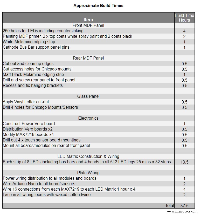
ビニール転写印刷を取得します。
ガラスをカットします。
MDFシートを表と裏にカットします。
LED用のフロントシートに穴を開けます。
MDFシートをペイントします。
ガラスにセンサー用の穴を開けます。
ガラスの裏側にビニール転写を貼り付けます。
MDFフロントボードにセンサーの穴を開けます。
フロントボードでセンサーモジュールのリベートをカットします。
MDFバックボードを切り取り、センサーアクセス用に4つのアクセス穴を開けます。
メラミンエッジストリップをMDFボードに追加し、白をフロントボードに、黒をリアボードに追加します。
背面のMDFボードを前面のMDFボードにねじ込みます。
Veroボード、1つの電源ボードと2つの配電盤を作成します。
4 x MAX7219ボードを変更し、LEDに配線を追加します。
今のところ、MAX7219の端でのみ接続してください。
すべてのモジュールとVeroボードをMDFフロントボードの背面に取り付けます。
フロントMDFボードに4つのLEDマトリックスをすべて構築し、256個のLEDをはんだ付けします。
すべてのBattとEarthの配線は、電源のVeroボードと配電盤から実行されます。
すべての電源をすべてのモジュールに接続します。
すべての配線をNano、MAX7219モジュール、RTC、温度センサー、タッチセンサー、ブザーに接続します。
配線テーブルに従って、変更されたMAX7219ボードからのすべての配線ルームをLEDマトリックスに接続します。
時計からリモートでPIRモジュールを接続し、PIR接続を接続します。
30秒の同期をマスタークロックに接続します(必要な場合)。
同時にタッチセンサーを固定するシカゴボルトを使用して、Glassフロントディスプレイパネルを取り付けます。
テスト。
表1は、この時計のおおよそのビルド時間を示しており、スキルレベルや、手渡す必要のある特殊なツールや作業スペースによって異なります。
そのリストにさらに40時間のプロトタイピングとプログラミング時間を簡単に追加できます。
ステップ14:建設ビニールステッカー
ビニールステッカー
<図>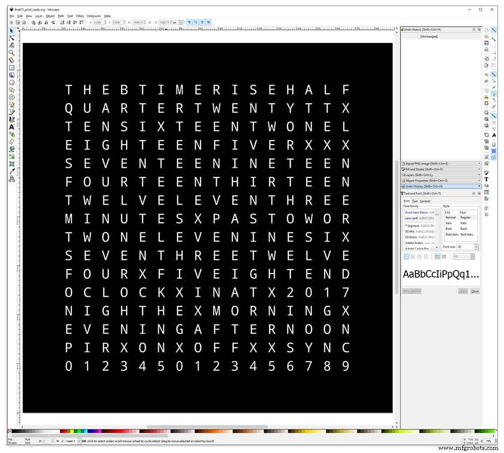
ビニールステッカーはInkscapeでデザインされています。
Inkscapeは、Windows、Mac OS X、GNU / Linuxで動作するプロ品質のベクターグラフィックソフトウェアです。イラスト、アイコン、ロゴ、図、地図、ウェブグラフィックなど、さまざまなグラフィックを作成するために、世界中のデザインの専門家や愛好家によって使用されています。
Inkscapeは、ネイティブ形式としてW3CオープンスタンダードSVG(Scalable Vector Graphics)を使用しており、無料のオープンソースソフトウェアです。
Wouter Devinckによる元のInkscapeデザインを彼のGitHubリポジトリからダウンロードし、自分のデザインに合うようにInkscapeで変更しました。ミニチュアプロトタイプでさまざまなバージョンを試してから、最終的なデザインを印刷に送りました。
ステッカーを逆に印刷することを忘れないでください!
私はRegalSigns&Graphicsという会社を利用しました。この会社は、ステッカーを黒のビニール、リバースカット、レタリングを取り除き、アプリケーションテープをすべて約27ポンドの付加価値税で提供していました。
彼らは私にとってかなり地元の人ですが、私はもう少しお金を払って、素敵な安全なボール紙のチューブでステッカーを届けました。
デザインを自分のマシンに適した形式で取得するのにいくつか問題がありましたが、最終的にはIllustratorからeps形式で送信しました。RegalSignsの非常に親切な人々が、適切なサイズに縮小しました。Inkscapeファイルをダウンロードできます。こちらはVINYLSTICKERです。
ビニールステッカーはリーガルサインから文字を取り除いたものなので、時間を大幅に節約できました。ステッカーの前面(ガラス)側にはプラスチックテープが、背面にはアプリケーションペーパーが付いています。通常、サイドテープからはがし、ステッカーを貼り付けてから、塗布紙をはがします。 LEDのディフューザーとして機能するため、アプリケーションペーパーをそのままにしておくことにしました。アプリケーションペーパーを置いたままにしていたので、適用する前にステッカーの周りの余分なペーパーを切り落としました。
<図>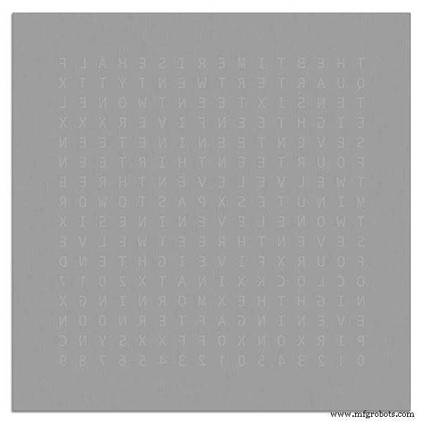
ステッカーの貼り付けは比較的簡単でした。自分で試す前に、ガラスへのビニールステッカーアプリケーションでいくつかのYouTubeビデオを必ず見てください。
ガラス
<図>
時計は4mmのフロートガラスを使用し、正確に500mmx500mmにカットされています。エッジが露出しているので、エッジも磨かれています。これはすべて私の地元のガラス工によって£20で行われました。
次に、5mmガラスドリルを使用してガラスパネルに5mmの穴を開けました。ガラスに穴を開ける方法については、YouTubeの動画をご覧ください。
最初にアセトンでガラスを洗浄し、ほこりがないことを確認しました(非常に重要)。次に、ステッカーに指紋が付いていないことを確認するために、プラスチック製の手袋をいくつか着用しました。
ガラスに非常に希釈した石鹸と水の混合物をスプレーした後、ステッカーからプラスチックフィルムをゆっくりとはがして、前面を露出させました。
ステッカーの文字が転写紙に接続されたままになるように、フィルムをゆっくりと非常に鋭角で剥がすことが重要です。ステッカーが完全に露出したら、濡れたガラスの表面に貼り付けます。
水と石鹸の混合物を使用すると、ステッカーをガラスの正しい場所に移動できます。次に、クレジットカードを使用し、ステッカーの中央から離れて気泡を取り除きます。ステッカーを一晩乾かしてから、ステッカーの裏側からガラスの4つの取り付け穴の上のビニールを切り取ります。
Brett11_print_ready.svg
ステップ15:メインボードの構築パート1
メインボード
<図>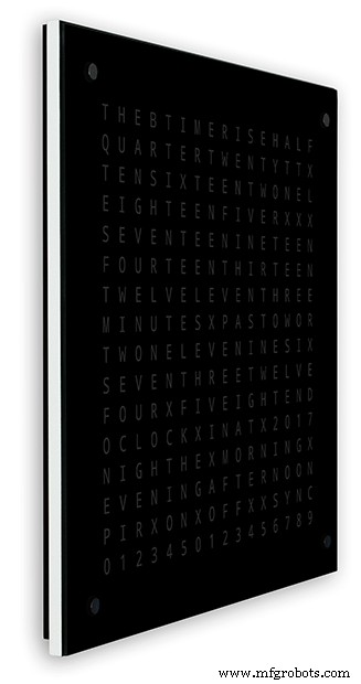
時計のメインボードは2枚の14mmMDFで構成されています。リアシートは、トップを除くすべての面でトップシートよりも10mm小さくなっています。上部には白いエッジがあり、背面には黒いエッジがあります。壁で見ると、時計の深さは14mmに見えます。
<図>
時計のメインボードは2枚の14mmMDFで構成されています。リアシートは、トップを除くすべての面でトップシートよりも10mm小さくなっています。上部には白いエッジがあり、背面には黒いエッジがあります。壁で見ると、時計は14mmの深さであるように見えます。
オリジナルのWouterDevinck Clockと「Catalan」Pijuanaバージョンでは、厚さ18mmのMDFシートが1枚使用され、PCBとコンポーネント用のスペースを作るために背面が配線されています。 2枚のMDFを使用することで、時間のかかるほこりっぽい配線ではなく、ジグソーを使用してバックボードを簡単に切り取ることができます。トップシートは503mmx 503mmで、ガラスの周りに1.5mmのオーバーラップを与えます。これにより、ガラスがノックから少し保護されます。
<図>
バックボードはジグソーを使用して切り抜かれ、14mmのコンポーネントスペースが可能です。
コンポーネントを含む最も深いPCBは、10mmの深さのMAX7219モジュールです。完了すると、リアボードがフロントボードに接着またはネジ止めされます。
フロントボードの構造
フロントボードには、6.5mmの穴と18mmの広い皿穴を通して光る256個のLEDがあり、ディスプレイ上の個々の文字と数字を照らします。
<図>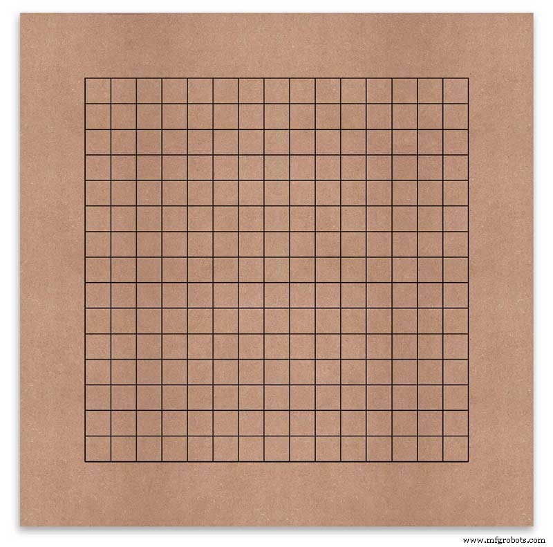
ボードは、各表示文字の中央にあるのドリル位置を示すためにマークアップされています。 500mmのディスプレイを使用してビニールシートを測定しました。文字は端から62.5mmの位置から25mm離れています。これらの線をMDFに描画しました。交差点が、ドリルポイントです。
<図>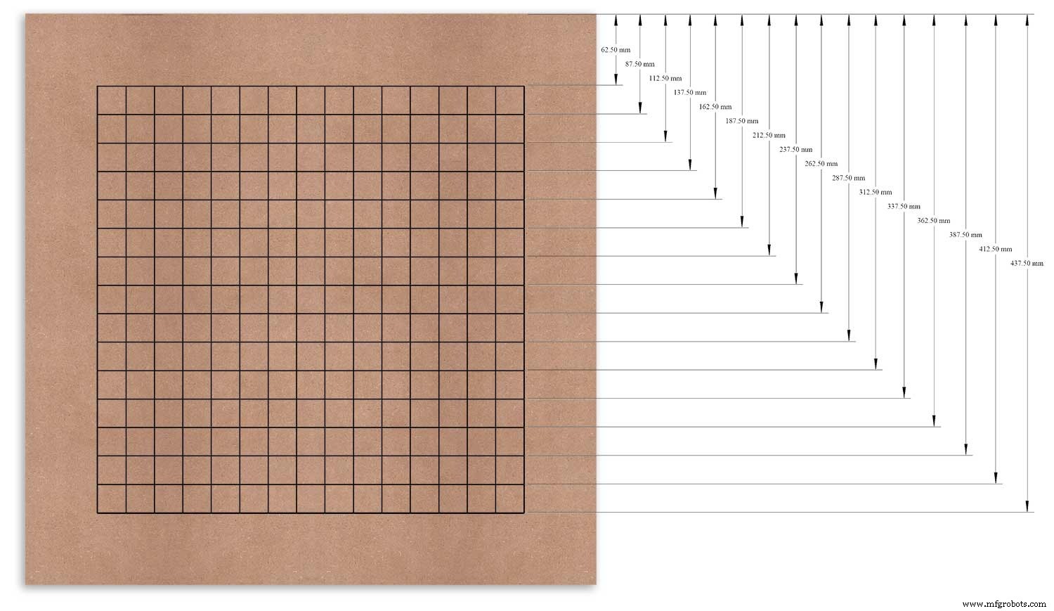
測定した基準点として上端を使用し、この点から各行にマークを付けました。
これは、左端をデータムとして使用して、垂直柱に対して繰り返されました。
<図>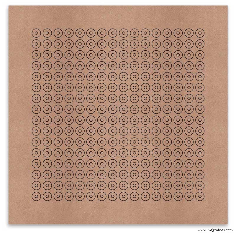
グリッドの交点は、6mmのLED取り付け穴と18mmの皿穴の中心点になります。
<図>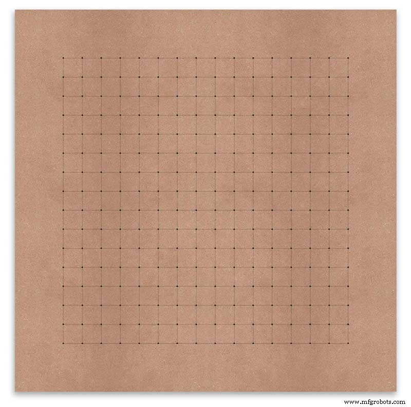
<図>
Using an automatic centre punch ( use a nail or screw if you don't have one) I punched the 256 intersection points of the grid.
<図>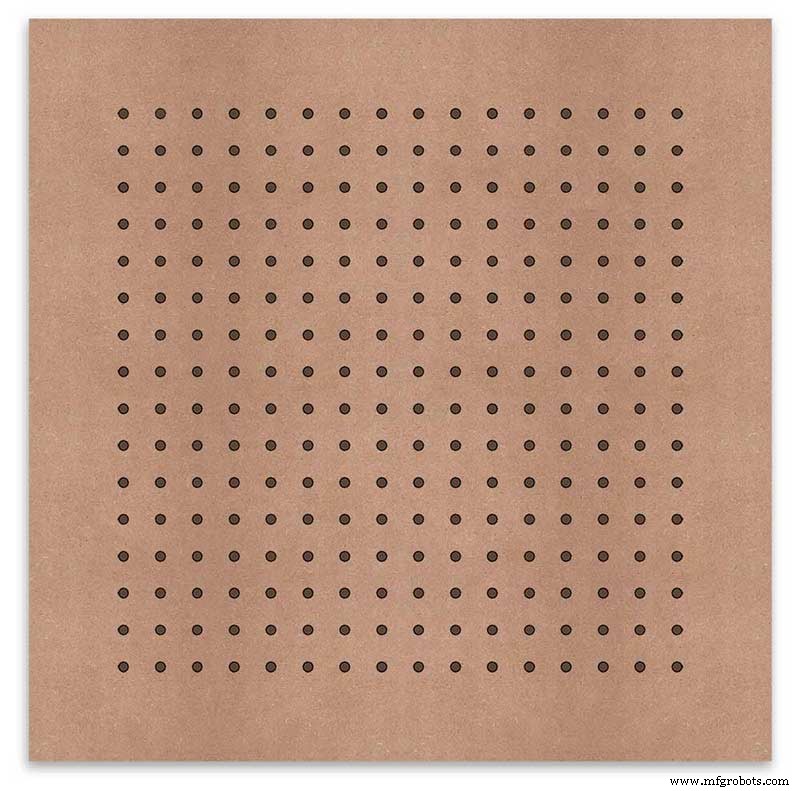
Using a drill bit to suite your LEDs (6mm in my case) and using the punched holes as a guide for the drill bit drill out all 256 LED mounting holes.
The next task is to drill the 256 18mm countersunk holes using a 20mm countersinking bit.
<図>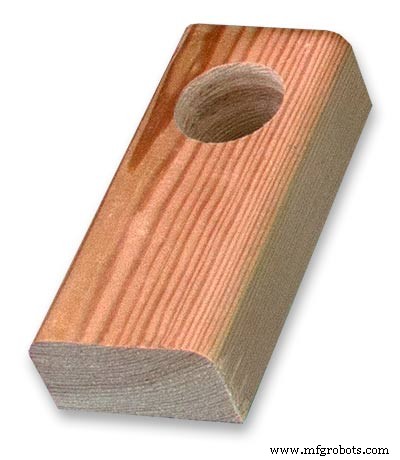
To keep the countersunk holes at a uniform depth and width I built a countersinking jig using an off cut of wood. To make the jig a hole is drilled in the wood off cut to just fit the silver rotating bezel of my drill chuck. Using a test piece of MDF the countersinking bit is then moved in and out of the chuck until a countersunk hole of the correct diameter is made when drilling through the hole upto the chuck in the off cut of wood. Once the correct distance is found the chuck is tightened and the main board is drilled 256 times by centring the hole in the wood over the existing 6mm holes then drilling down until the chuck bezel hits the hole in the countersinking jig.
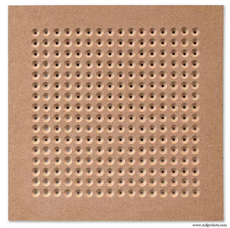
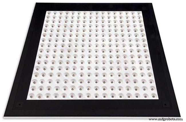
<図> Completed front board with 256 countersunk holes and 6mm holes for the LEDs.
<図>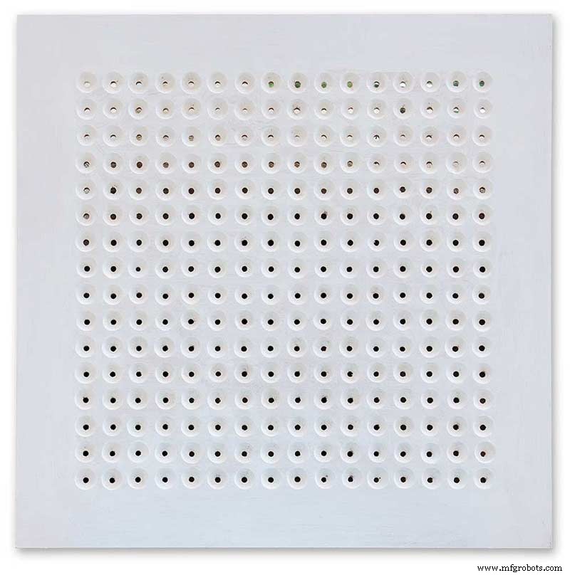
The board is then rubbed down and primed using MDF primer and painted white so the countersunk holes reflect the light from the LEDs.
<図>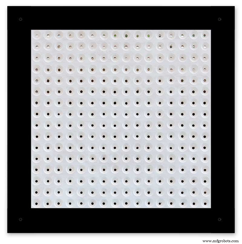
A black edge is painted around the outside edge to hide the board as the glass is 1mm shorter all round. This setback also helps the glass disappear from view on the final clock.
Four 5mm holes are then drilled in the corners to take the Chicago Fasteners. The Chicago Fasteners hold the glass in place, hold the touch sensors and provide a touch sensitive pad on top of the glass. The fasteners have 3mm shafts and will have a small bit of rubber tape wrapped around the shafts to protect the glass.
<図>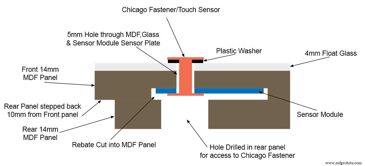
Turn the board over and drill a rebate with a forstner bit to take the four touch sensors. This hole will be offset from the hole drilled in the previous step.
Wall Mounts
The clock is fixed to the wall by two metal picture hanging mounts.
<図>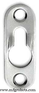
These are recessed into the frame so the highest point of the bracket is level with the frame.
Two 2" countersunk No6 screws sit in these bracket and hold the clock to the wall with a bit of tension so the dust seal is compressed.
Step 16:Construction Touch Sensor Mounting <図>
The touch sensor modules are fixed to the front panel using the Chicago Fastener bolts. The Chicago Fastener bolts then act as touch sensors.
A 5mm hole is drilled through the sensor pad on the module to allow the Chicago Fastener bolt to pass through.
<図>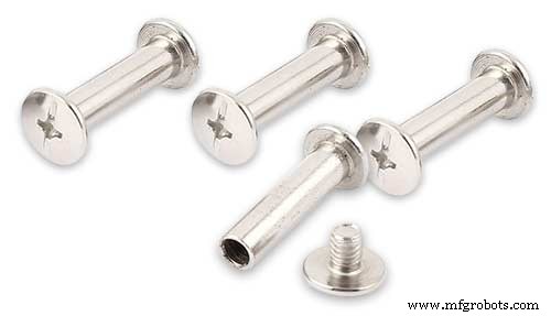
The sensor pad is insulated by the MDF panel and a plastic washer.
<図>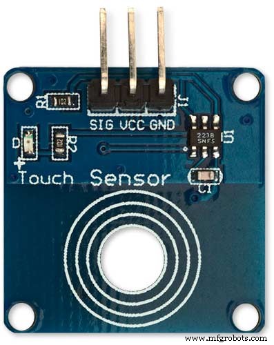
The touch pad on the sensor module has a 5mm mounting hole drill through the sensor.
<図>
Touch sensors in rebates behind rear panel. Holes drilled into rear panel allows access to the Chicago Fasteners that hold the sensors/glass front in place.
<図>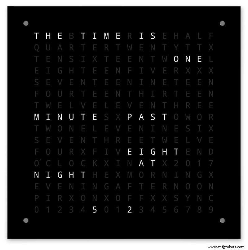
Clock front panel with four Chicago Fastener tops acting as touch plates.
Step 17:Electronic Components &Modules <図>
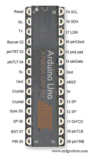
ATmega328 pin connections in case you want to prototype the circuit on an Arduino Uno. Note BST pin 07 is not used.
Pin label numbers refer to Arduino IDE numbers.
<図>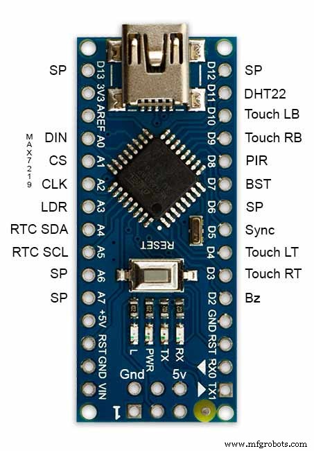
LEDs
<図>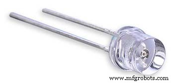
Make sure you purchase your LEDs from a good source. These LEDs will be on for many hours a day. I have has problems with LEDs failing after a few weeks use.
My LEDs Specs
5mm White Flat Top LEDs offering a pure and consistent colour with a wide angle ultra bright light output.
Colour :White
Quantity :256
Lenses Type :Round Flat Top
Crystal ClearBrightness :13000mcdForward
Voltage :3.2v - 3.8v
Forward Current :20mA (typical), 30mA (Max)
Viewing Angle :120 degrees
DHT22 Temperature &Humidity Sensor
<図>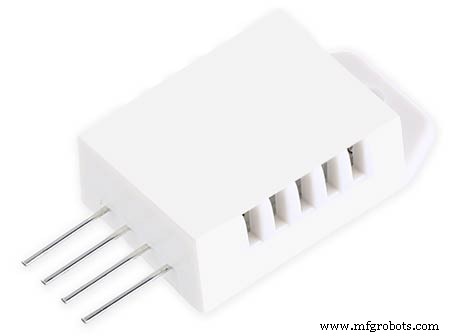
The DHT22 is a basic, low-cost digital temperature and humidity sensor. It uses a capacitive humidity sensor and a thermistor to measure the surrounding air, and sends out a digital signal on the data pin.
You can only get new data from it once every 2 seconds, so sensor readings can be up to 2 seconds old.
Simply connect the first pin on the left to 3-5V power, the second pin to your data input pin and the right most pin to ground.
To prevent the temperature of the inside clock case being measured the top and left side vent of the DH22 are covered over with tape. This also stops dust being drawn into the clock case.
<図>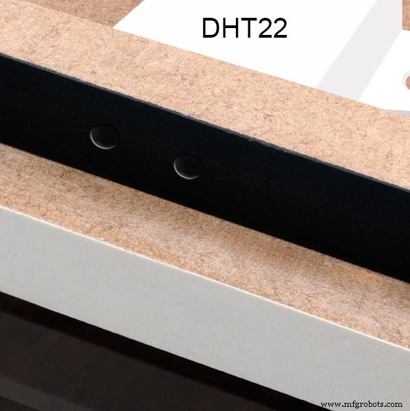
The DHT22 is mounted with its right open side mounted tight against the lower rear cover.Two small holes are drilled in the lower edge of the rear MDF board to allow air from the room to circulate around the sensor.
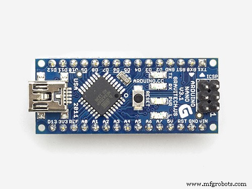
Arduino NANO
<図>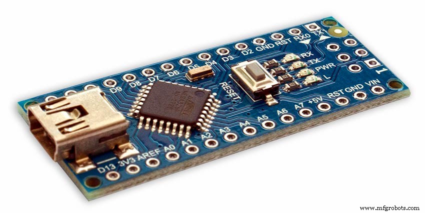 <図>
<図> 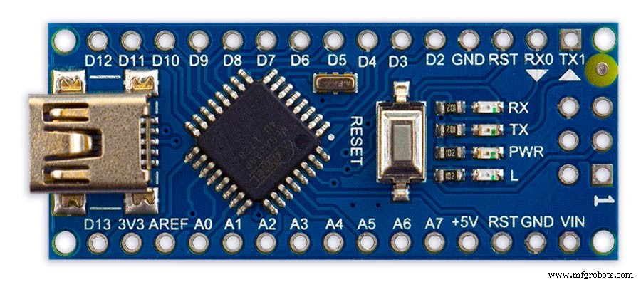
PowerThe Arduino Nano can be powered via the Mini-B USB connection, 6-20V unregulated external power supply (pin 30), or 5V regulated external power supply (pin 27). The power source is automatically selected to the highest voltage source.
Memory
The ATmega328 has 32 KB, (also with 2 KB used for the bootloader.
The ATmega328 has 2 KB of SRAM and 1 KB of EEPROM.
Input and Output
Each of the 14 digital pins on the Nano can be used as an input or output, using pinMode(), digitalWrite(), and digitalRead() functions. They operate at 5 volts. Each pin can provide or receive a maximum of 40 mA and has an internal pull-up resistor (disconnected by default) of 20-50 kOhms. In addition, some pins have specialized functions:Serial:0 (RX) and 1 (TX). Used to receive (RX) and transmit (TX) TTL serial data. These pins are connected to the corresponding pins of the FTDI USB-to-TTL Serial chip.
External Interrupts:2 and 3.
These pins can be configured to trigger an interrupt on a low value, a rising or falling edge, or a change in value. See the attachInterrupt() function for details.
PWM:3, 5, 6, 9, 10, and 11. Provide 8-bit PWM output with the analogWrite() function.
SPI:10 (SS), 11 (MOSI), 12 (MISO), 13 (SCK). These pins support SPI communication, which, although provided by the underlying hardware, is not currently included in the Arduino language.
LED:13. There is a built-in LED connected to digital pin 13. When the pin is HIGH value, the LED is on, when the pin is LOW, it's off.
The Nano has 8 analog inputs, each of which provide 10 bits of resolution (i.e. 1024 different values). By default they measure from ground to 5 volts, though is it possible to change the upper end of their range using the analogReference() function. Analog pins 6 and 7 cannot be used as digital pins. Additionally, some pins have specialized functionality:I2C:4 (SDA) and 5 (SCL). Support I2C (TWI) communication using the Wire library (documentation on the Wiring website).
There are a couple of other pins on the board:AREF. Reference voltage for the analog inputs. Used with analogReference().リセットします。 Bring this line LOW to reset the microcontroller. Typically used to add a reset button to shields which block the one on the board.
Communication The Arduino Nano has a number of facilities for communicating with a computer, another Arduino, or other microcontrollers. The ATmega328 provide UART TTL (5V) serial communication, which is available on digital pins 0 (RX) and 1 (TX). An FTDI FT232RL on the board channels this serial communication over USB and the FTDI drivers (included with the Arduino software) provide a virtual com port to software on the computer. The Arduino software includes a serial monitor which allows simple textual data to be sent to and from the Arduino board. The RX and TX LEDs on the board will flash when data is being transmitted via the FTDI chip and USB connection to the computer (but not for serial communication on pins 0 and 1). A SoftwareSerial library allows for serial communication on any of the Nano's digital pins. The ATmega328 also support I2C (TWI) and SPI communication. The Arduino software includes a Wire library to simplify use of the I2C bus. To use the SPI communication, please see ATmega328 datasheet.
TTP223 Touch Sensor Module
<図>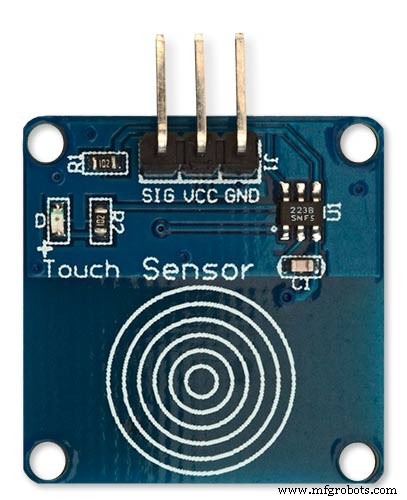
The touch Sensor Module is bolted to the front panel using the glass mounting bolts. The bolt goes through a 5mm hole drilled in the middle of the sensor.Note the mounting bolt is touched to trigger the sensor but is insulated from the sensor itself through plastic washers. Four of these modules are used in the clock one mounted on each corner of the glass.
<図>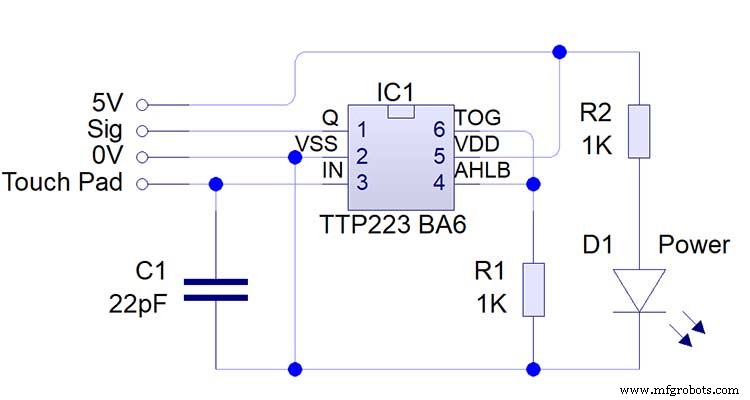
Note the LEDs are not required and are removed from the modules (just break them off) to save power.
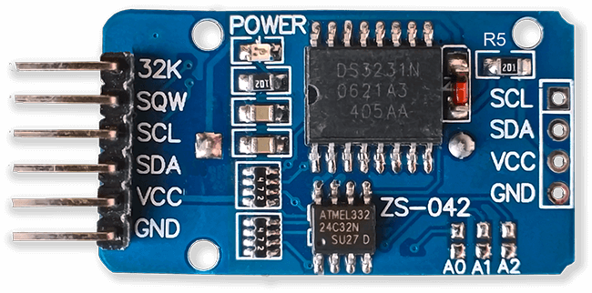
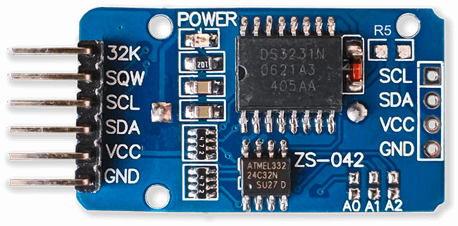
DS3231 AT24C32 I2C Precision Real Time Clock Module
My clock uses a DS3231 AT24C32 I2C Precision Real Time Clock Module.The module comes supplied with a Lithium-Ion rechargeable battery see diagram below. I use a non rechargeable battery so have removed resistor R5 from the module.
<図>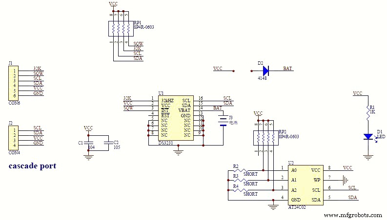 <図>
<図> 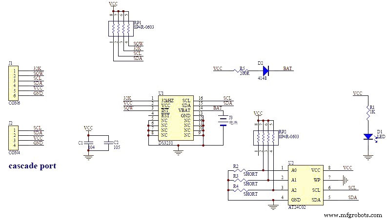
<図>
<図>
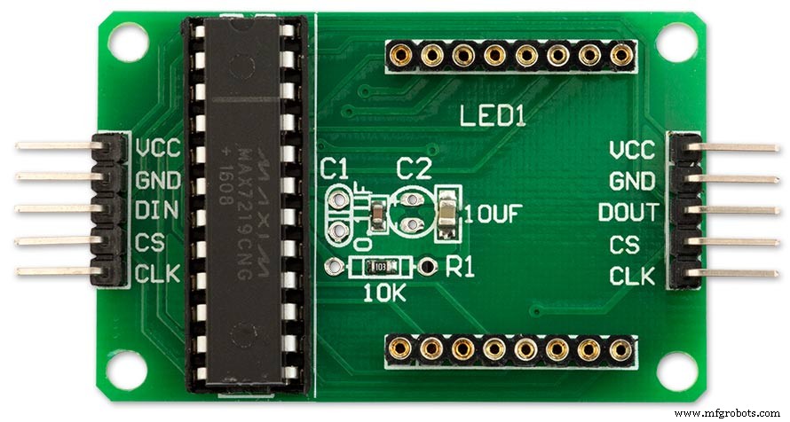
MAX7219 Display Module
<図>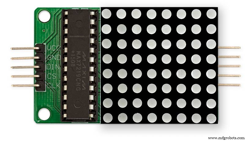
<図>
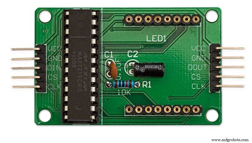
MAX7219 LED current limiting
The max current through the LEDs is set by a single resistor R1 on the module. The value of resistor can be found from the table below.
<図>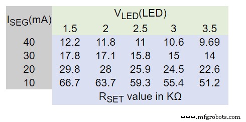
The module comes with a 10K resistor preinstalled but this can be removed and a resister to match your LEDs current added in its place. My LEDs Forward Voltage is 3.2v - 3.8v @ 20mA. They can handle 30mA max but for long LED life 20mA is best. I have used 22KΩ resistors which will limit the current to around 20mA when the light levels are at their peek.
See setting automatic brightness levels.
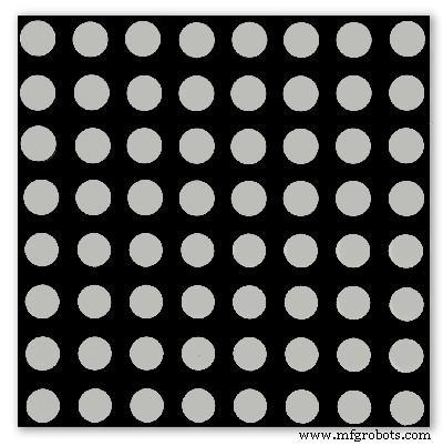
1088AS LED Dot Matrix display
<図>
1088AS LED Dot Matrix display view of lower edge Pins 1 to 8 left to right.
This is used for prototyping and is not required in the final project.
LDR
<図>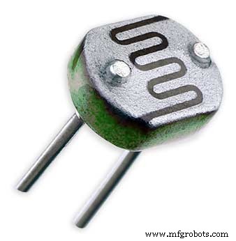
An LDR is used to sense the ambient light levels. The LDR is around 500Ω in bright light and 10MΩ in the dark.
<図>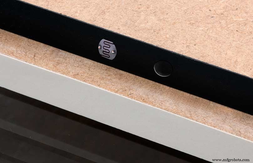
The LDR is positioned underneath the clock on the rear MDF panel.
<図>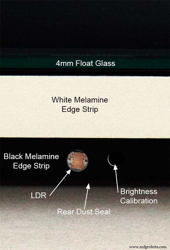
Next to the LDR is a hole to give access to the trimmer resister to calibrate the LED brightness control.
Component List
<図>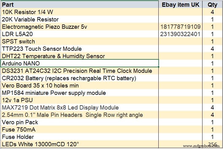
Step 18 Dust Seals
To prevent ingress of dust two dust seals are fitted.
<図>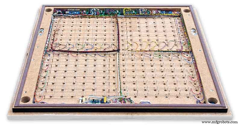
On the rear MDF board a 2mm soft foam rubber dust seal is fitted. When the clock is hung on its hanging hooks the seal is under pressureand seals the back of the clock to the wall.
The seal is self adhesive and is fitted with a 5mm gap to the edge of the rear MDF board.
<図>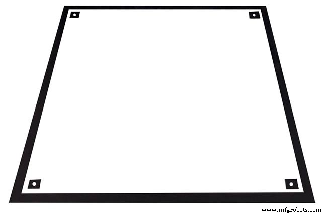
<図>
On top of the front board to prevent dust getting under the glass a strip of self amalgamating rubber is fitted 5mm from the board edge.
To prevent the glass from cracking when the Chicago bolts are tightened 4 small square of rubber are also fitted around the holes in the glass.
I punched holes for the Chicago Bolts in the rubber with a leather punch.
Step 19:Schematic
Nano Connections
<図>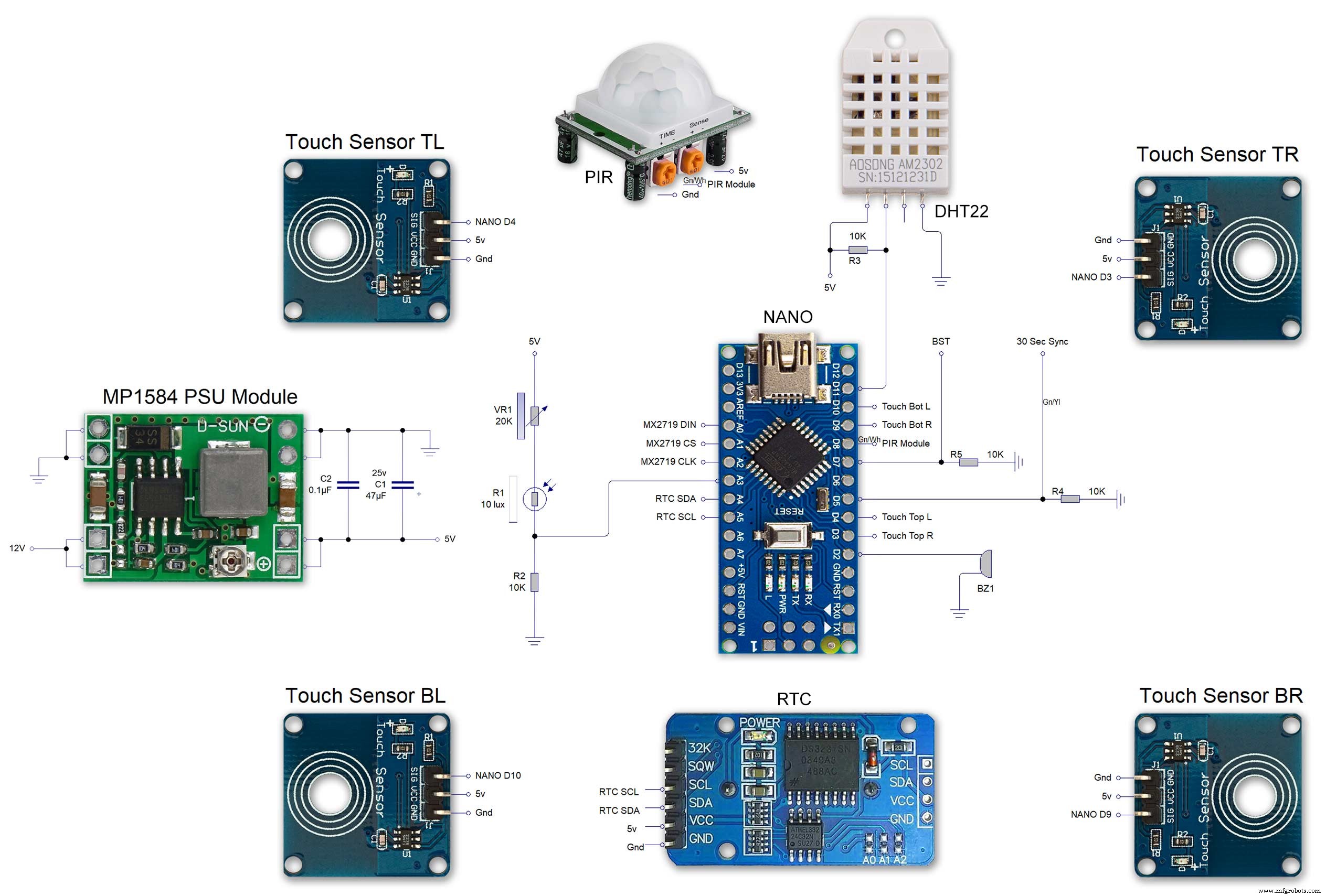
The connections to the Arduino Nano. Download the full size file from the hardware section
MAX2719 connections
<図> <図>
<図>  <図>
<図>  <図>
<図> 
The 4 MAX7219 modules and the connected LED matrixes.
<図>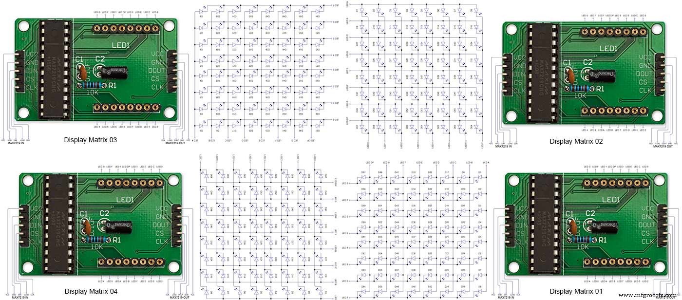
Note the LED display matrixes are rotated anti-clockwise 90 degrees from each other starting from display matrix 01.Display Matrix 01 input is wired to the Arduino CLK, DIN and LOAD the output is taken to the input of Display matrix 02 etc etc.
Step 20:Wiring Building the LED Matrixes
Module Locations
<図>
The module locations are shown above. The four sensors are located in the recesses on the main board behind the rear board. Holes are cut into the rear board to allow access for fit the Chicago Bolts/Sensor pads.
The four MAX7219 Display Modules are soldered together and are mounted in the centre top of the board. This keeps the data links between the boards as short as possible.
The Arduino Nano is mounted on the left of the MAX7219 Display Modules and the RTC on the right. The RTC battery holder on the base of the RTC module is recessed into the main board.
The Vero board containing the power module is located on the lower part of the board. There are two power distribution boards mounted on the top of the clock. The main 5v 2A feed cable is taken to both of these boards and power is then distributed to the other boards from these points.
The MAX7219 board power is fed from the left board and daisy chained through each board then taken out the forth board to ensure they are fed with 0v and 5v from both ends.
<図> The LED locations are shown. The LED matrixes each contain 64 LEDs and are labelled 1 to 4.
These correspond to the 4 MAX 7219 modules mounted above numbered 1 to 4 left to right. Note this is the rear of the clock so number will be revearsed.
<図>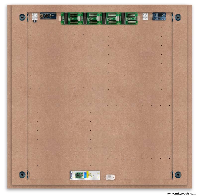
The LED Matrixes are built up off 2 types of BUS Bars per module. A Cathode Bus at 10mm high and an Anode BUS bar at 2mm high.
There are 8 Cathode and 8 Anode BUS Bars per module. Each module has 16 x 15mm panel pins hammered into the board in the position shown to support the 10mm high Cathode BUS.
<図>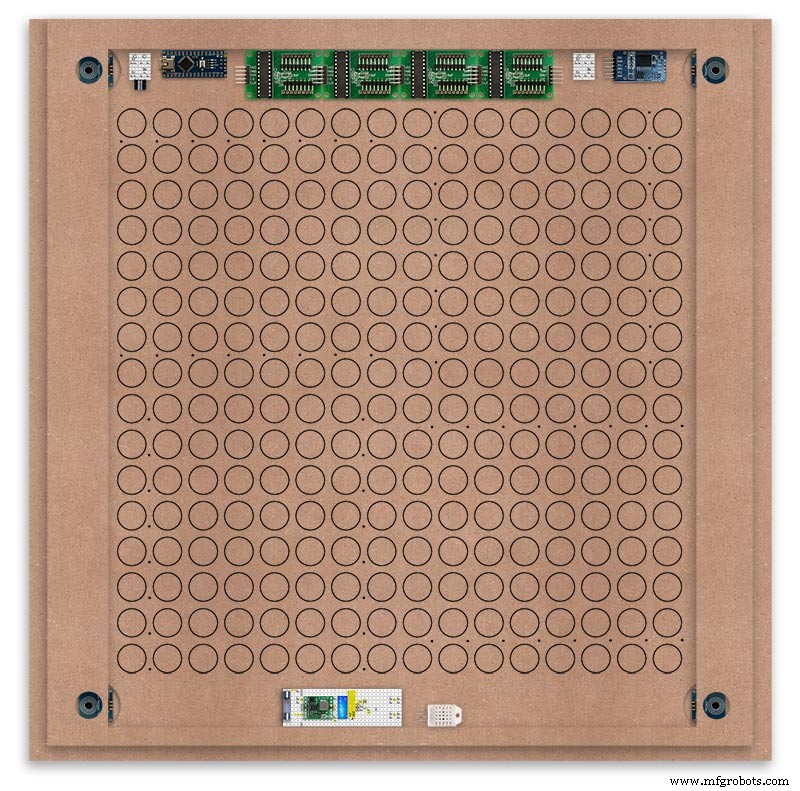
The 15mm panel pins are hammered in 5mm (I used a 10mm piece of metal bar as a gauge) leaving 10mm as Cathode BUS bar support pins.
As shown above the pins correspond with the thick parts of the board not the recess for the LEDs on the front of the board. Note the LED recess is on the front of the board and can't be seen from the back.
<図>
0.9mm copper wire is then soldered to each pair of pins to form the Cathode BUS Bar.
Note the rotation of each module and also the modules are in reverse as it is the back of the board the LEDs are connected to.
<図>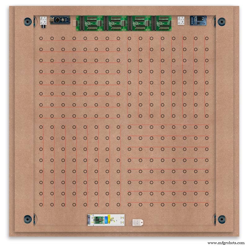
The Anode BUS Bars are shown below in Red and are supported off each LED Anode about 2mm off the MDF board. No Pins required.
<図>
Both Cathode &Anode BUS Bar locations are shown below.
Each LED is connected to an Anode and Cathode of the Matrix.
Step 21:Wiring the LEDs
LEDs
<図>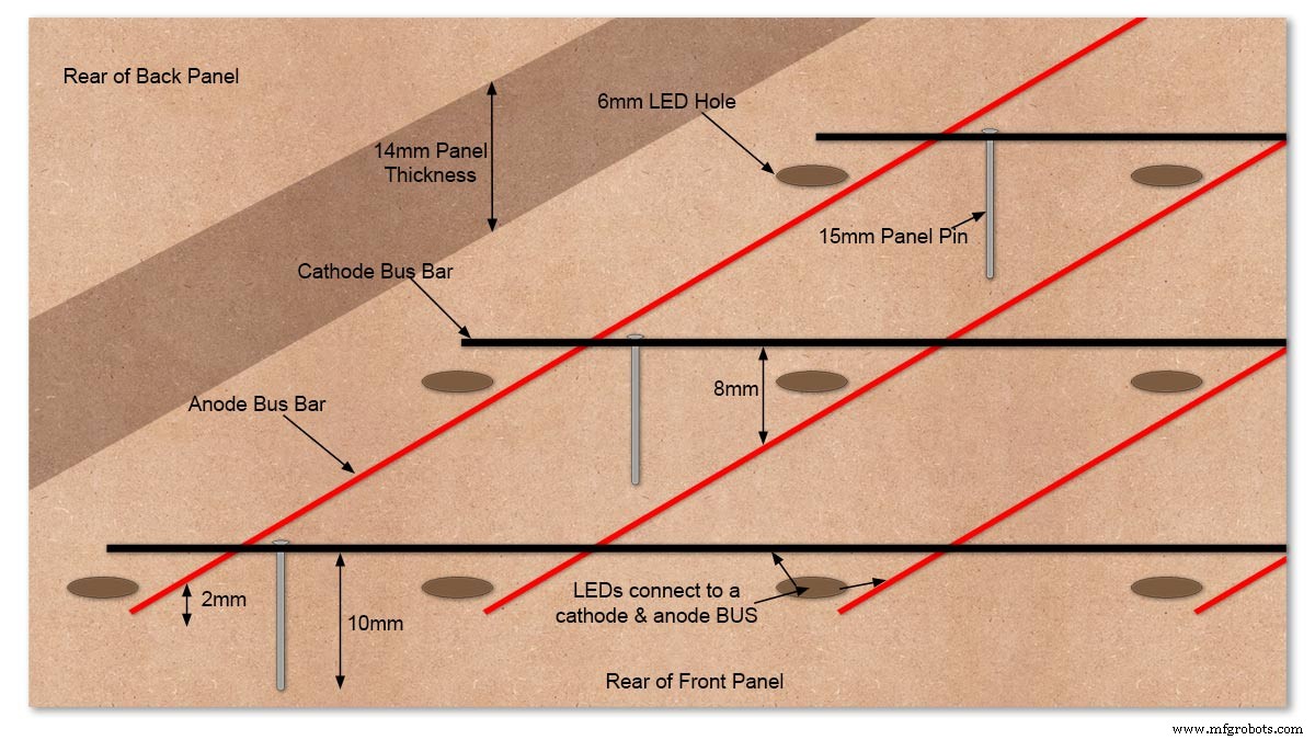
Diagram showing Bus Bar layout with panel pins supporting the Cathode Bus. This module has horizontal Cathode and vertical Anode Bus Bars.
<図>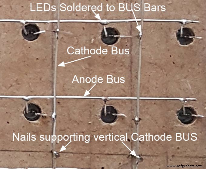
Close up section of Module wiring.The Cathode BUS Bars run vertically and the Anode BUS Bars run horizontally on this module. The Anode &Cathode BUS Bars have an 8mm vertical separation.
<図>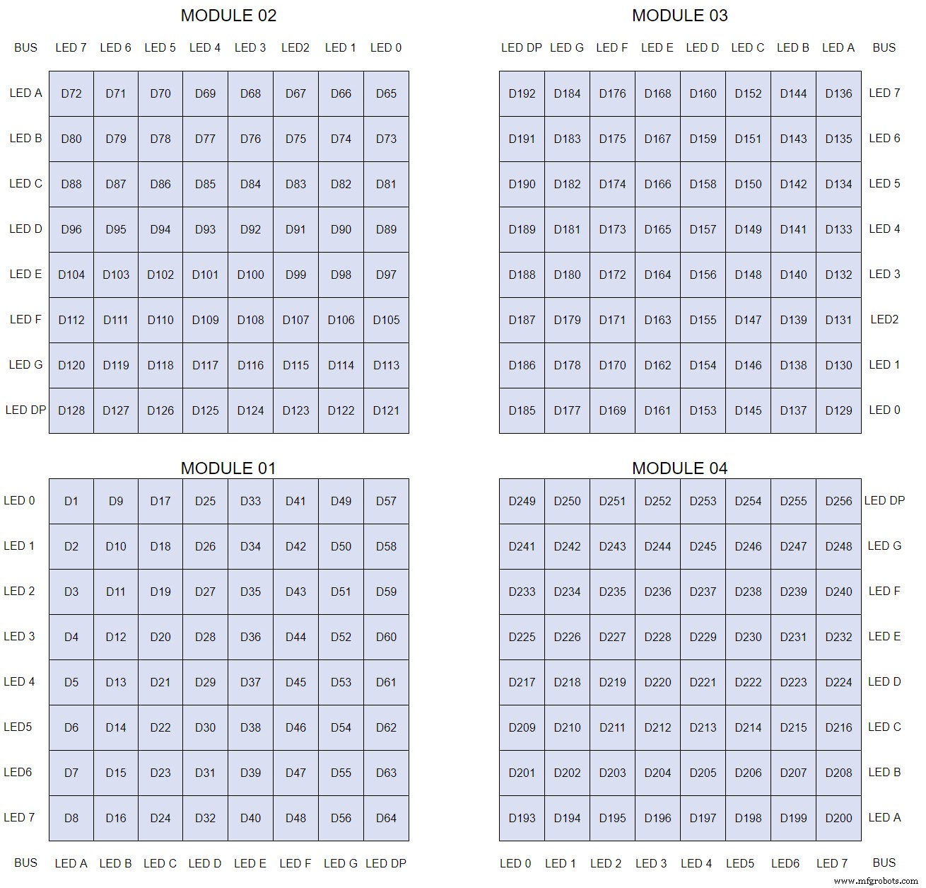
The LEDs are connected to the matrixes and MAX7219 modules from the rear. The LED positions will be reversed and of course rotated 90° relative to the next module. This makes it very complicated connecting the correct LEDs and Bus bars from the rear of the board. The table below shows the LED positions in the blue boxes with the BUS Bar matrix position in black around the outside as they appear from the back of the front MDF board.
<図>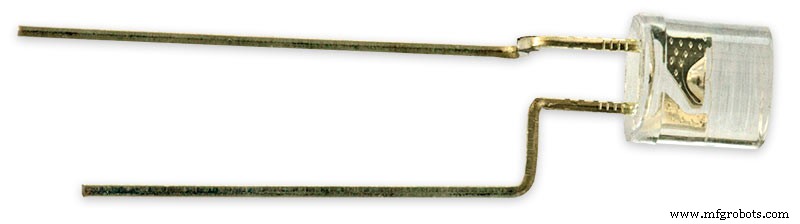
The LEDs are bent in a jig to keep the position in the display constant and to speed up construction. Each LED has four bends two on each leg that's 1024 in total! The Cathode leg is bent 90° from the Anode.
<図>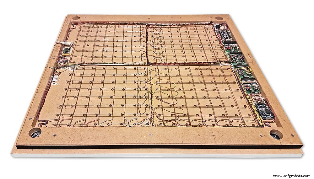
The Matrix grids are wired to the corresponding pins on the MAX7219 modules according to the layout table.
<図>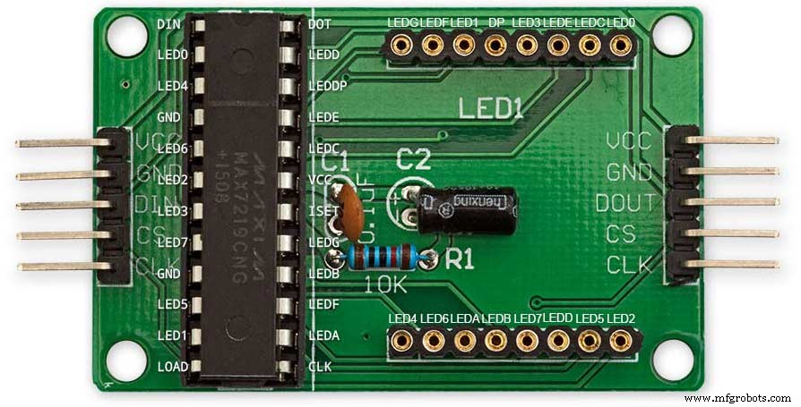
There are 16 wires to each module.
<図>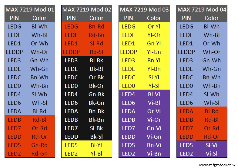
Table 1 Module LED Matrix Wiring Colour Code is shown above.
Each Module has 16 wires connecting it to the LED Matrixes. I have used 50pr 0.5mm cable so the last 14pr colours are duplicated. On Mod 4 I went out of order and missed out the Sl/Vi at the start so have put it in at the end.
Step 22:Wiring Modifying the MAX7219 Modules <図>
Before wires can be connected to the MAX 2917 modules they will need to be modified.
<図>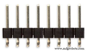
Two sets of 8 90° pin connectors will to be soldered to the lower edge of the existing LED matrix connector.
<図>
Modified MAX7219 module with 90° pin connectors soldered in place to the bottom of the old LED Matrix connectors.
Wires are taken away from these points to the LED matrix on the main MDF board as per the LED Matrix Wiring Colour Code table on the previous step.
<図>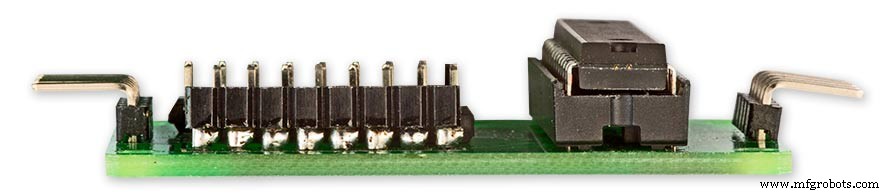
Side view showing the pins soldered to the side of the old LED Matrix connector pins just above the PCB.
Note if your MAX7219 Module does not have surface mount components the 90° pin connectors may need to be trimmed back so they don't foul R1, C1 or C2.
MAX7219 LED current limitingThe max current through the LEDs is set by a single resistor R1 on the module. The value of resistor can be found from the table below.
<図>
The module comes with a 10K resistor preinstalled but this can be removed and a resistor to match your LEDs current added in its place.
My LEDs Forward Voltage is 3.2v - 3.8v @ 20mA. They can handle 30mA max but for long LED life 20mA is best. I have used 22KΩ resistors which will limit the current to around 20mA when the light levels are at their peek.
Note this sets the max current through your LEDs actual brightness is controlled by the LDR/software/ trimmer resistor and will usually be far less than this.
Setting Automatic Brightness Levels
The clock automatically senses the ambient light and adjusts the LEDs accordingly.
When first installed the clock will need to be calibrated to the maximum light levels in its actual location.
<図>
Connect a mobile, laptop/tablet etc via a suitable cable to the mini USB port of the clock and open an app to monitor the serial port.
I use Slick USB 2 Serial Terminal on my S7 via an OTG cable and USB to mini USB cable.
<図>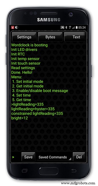
The clock will reboot and after the initial start screen you will see the following data updating down the screen.
You don't need to worry about lightReading or constrained lightReading+hyster just light reading, and bright.
With the clock in position and the ambient light at its maximum levels carefully insert a flat bladed jewellers screwdriver into the access hole just to the right of the light sensor.
Turn the screwdriver slowly until the light reading =600 (or your level set in brightness.cpp) and bright =15.
Your clock will now go to max brightness when the ambient light is at its maximum.
If you turn the screwdriver too far the light reading will go over 600 but the bright reading will not increase.
If you want the clock to be dimmer right across the range of ambient light levels adjust the light reading to a level less than 600 at max ambient light levels.
Note when bright=15 this will output the max current to the LEDs. The max current is set by R1( RSET) on the MAX7219 module and this should be chosen for your type of LED used in the display.
Step 23:Wring Mini USB Port <図>
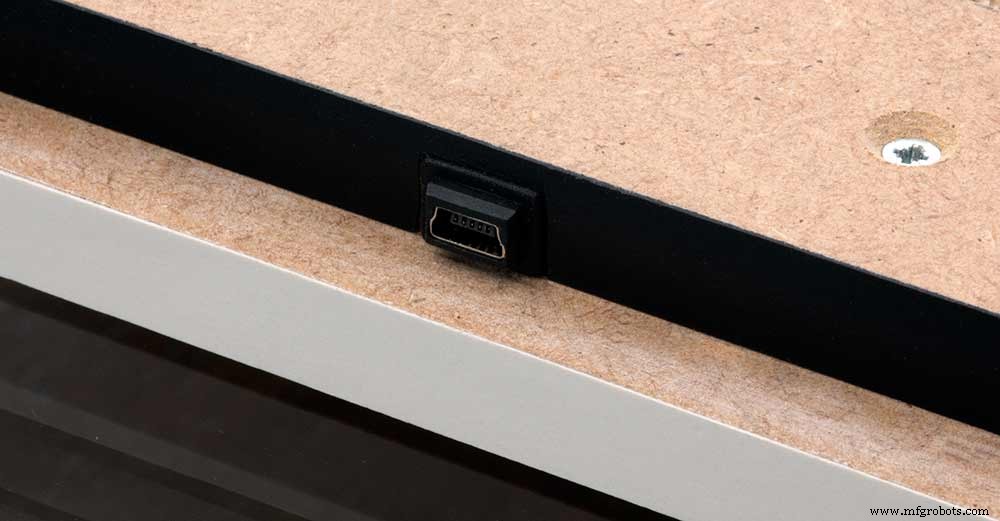
To allow adjustment/checking of light levels and programming of the clock a Mini USB socket is cut into the right hand side of the rear MDF sheet.
I have used a 25cm 90° Right angle Mini USB Male to Female Extension Cable and stripped back the insulation sleeve and shielding to expose the wires. This allows the cable to bend around the sharp angles and tight spaces of the enclosure.
Step 24:PIR Controlled Display Shutdown
This is optional as a Doppler Radar module can be fitted inside the clock instead.
See next section.
The PIR when enabled on the word clock menu (bott left PIR On, bott right PIR Off) turns on the display when movement is detected in the room.
When no movement is detected the display turns off after a set period of time. When the PIR is enabled the displays shows "PIR ON" and when disabled (display always on) it shows "PIR OFF" Note when the PIR is not enabled the display is always On.
The PIR module is fitted remote from the clock in a modified chrome light switch box. The box is cut into a plasterboard wall and also contains a switch to turn the clock off. The module itself is very small and can be mounted in a tiny enclosure if you don't want it on show. It will not work behind glass so if you wanted to mount it on the clock a hole would need to cut in the glass. This is very easy to do with a large hole cutter.
<図>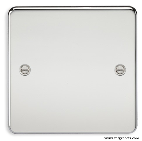
A blank chrome switch plate and back box are used to house the power switch and PIR module.
<図>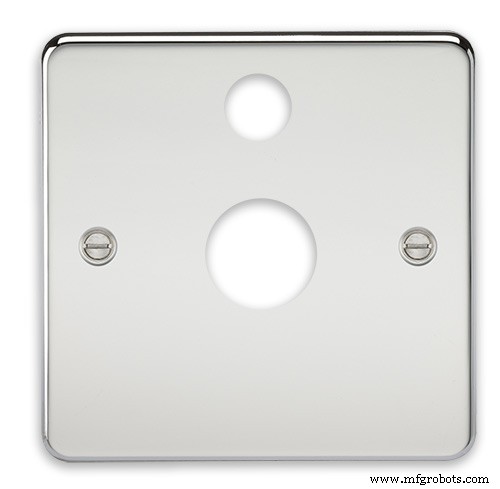
Two holes are drilled in the blank switch plate for the power switch and PIR lens.
The hole are centre punched, pilot drilled and then drilled out just big enough for a step cutter to fit through. The hole for the PIR diffuser is cut just big enough for the lens to go through with a friction fit.
<図>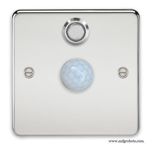
The completed switch plate.
<図>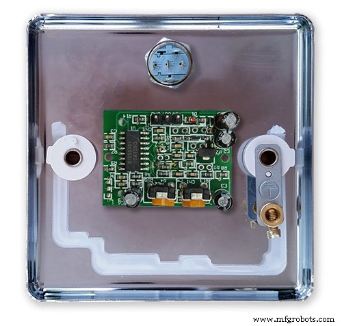
The 12 volt supply +ve is terminated on the switch with the 0v terminated on the earth screw.
12 volts is then fed back upto the clock PSU Vero board from the other side of the switch and again the earth screw. 5 volts are fed from the clock PSU Vero board to supply the PIR module.
The 5 volts and PIR sensor wire to the clock terminate on PCB header sockets. These are is plugged into the PIR Module header pins. The sync cable is terminated on a header pins and connects to the Master Clock 30 second sync cable via a single header socket.
<図>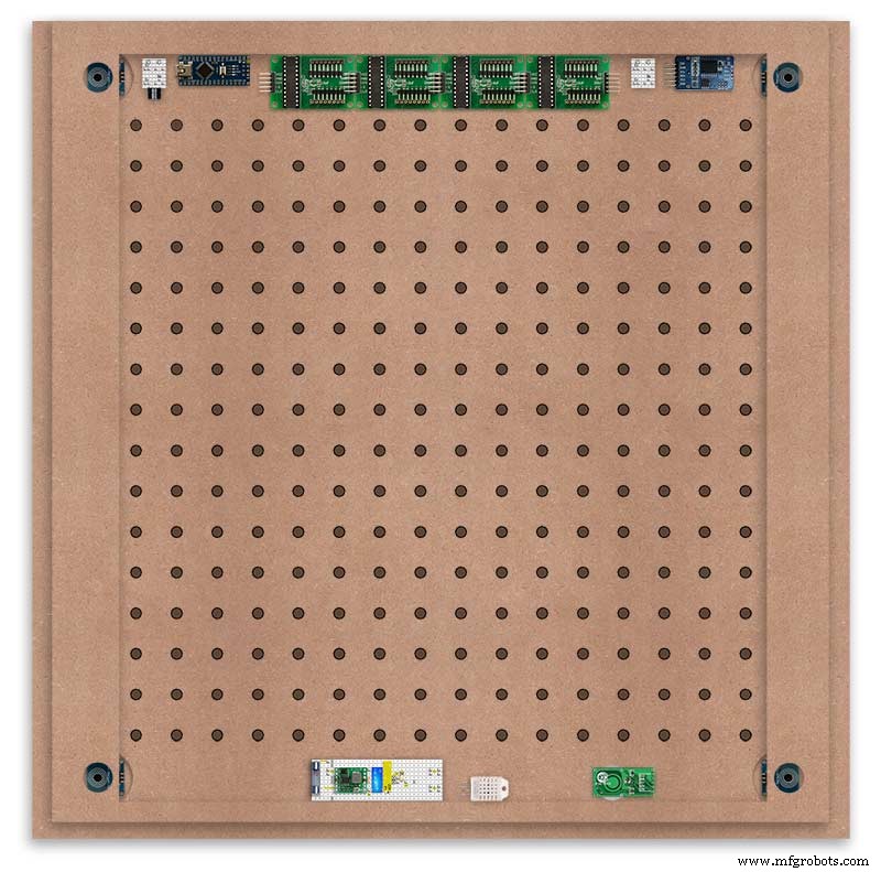
The PIR has 2 trimmer resistors for adjusting sensitivity and also length of time the PIR &display stay activated.
PIR On/Off Control:The PIR is turned on and off in word clock mode by touching the bottom left sensor to turn the PIR on or by touching the right sensor to turn the PIR off. Note when the PIR is set to off the display stays on permanently. When you change the PIR setting the work "PIR ON" or "PIR OFF" is displayed for 5 seconds.
When initial power up the default is PIR off if you switch the PIR On straight away the display will go off as the PIR takes a minute or so to initialise before detecting movement.
Photo 6 &7 "PIR ON" or "PIR OFF" are displayed for 5 seconds when PIR setting is changed.
Step 25:Doppler Radar Control Option
Optional Doppler Radar Module can be added in place of the PIR above.
<図>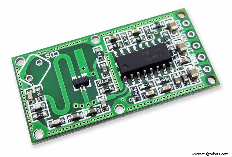
The Doppler Radar when enabled on the Word Clock menu (bott left PIR On, bott right PIR Off) turns on the display when movement is detected in the room. A check is made for motion on every quarter hour. When no movement is detected the display turns off until movement is detected again.
When the PIR is enabled the displays shows "PIR ON" and when disabled (display always on) it shows "PIR OFF" Note when the PIR is not enabled the display is always On. Unlike PIR modules the Doppler Radar module can see through glass and plastic and is fixed into the case of the clock behind the glass and PVC sticker. The module has a range of around 5m or 16' 5".
<図> Doppler Radar Module fixed inside the case. A hole is drilled in the front panel to allow the module to monitor the room.
<図>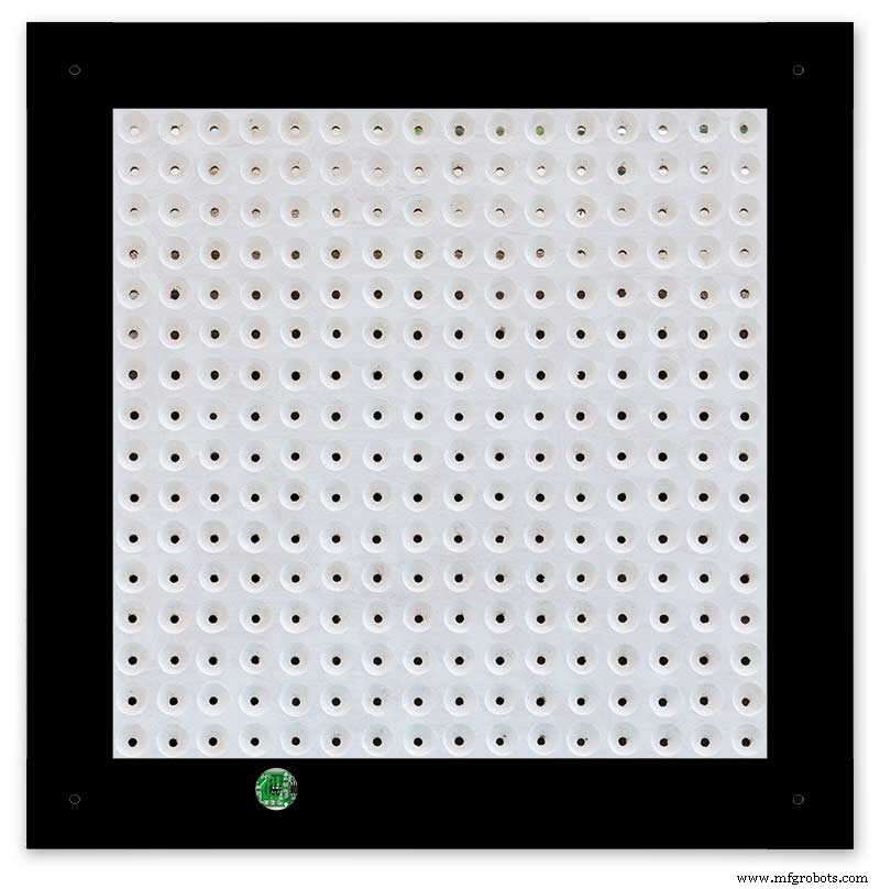
Front panel showing hole through to the Doppler Radar module microwave sensor.
The module is hidden from view behind the PVC sticker and glass.
<図>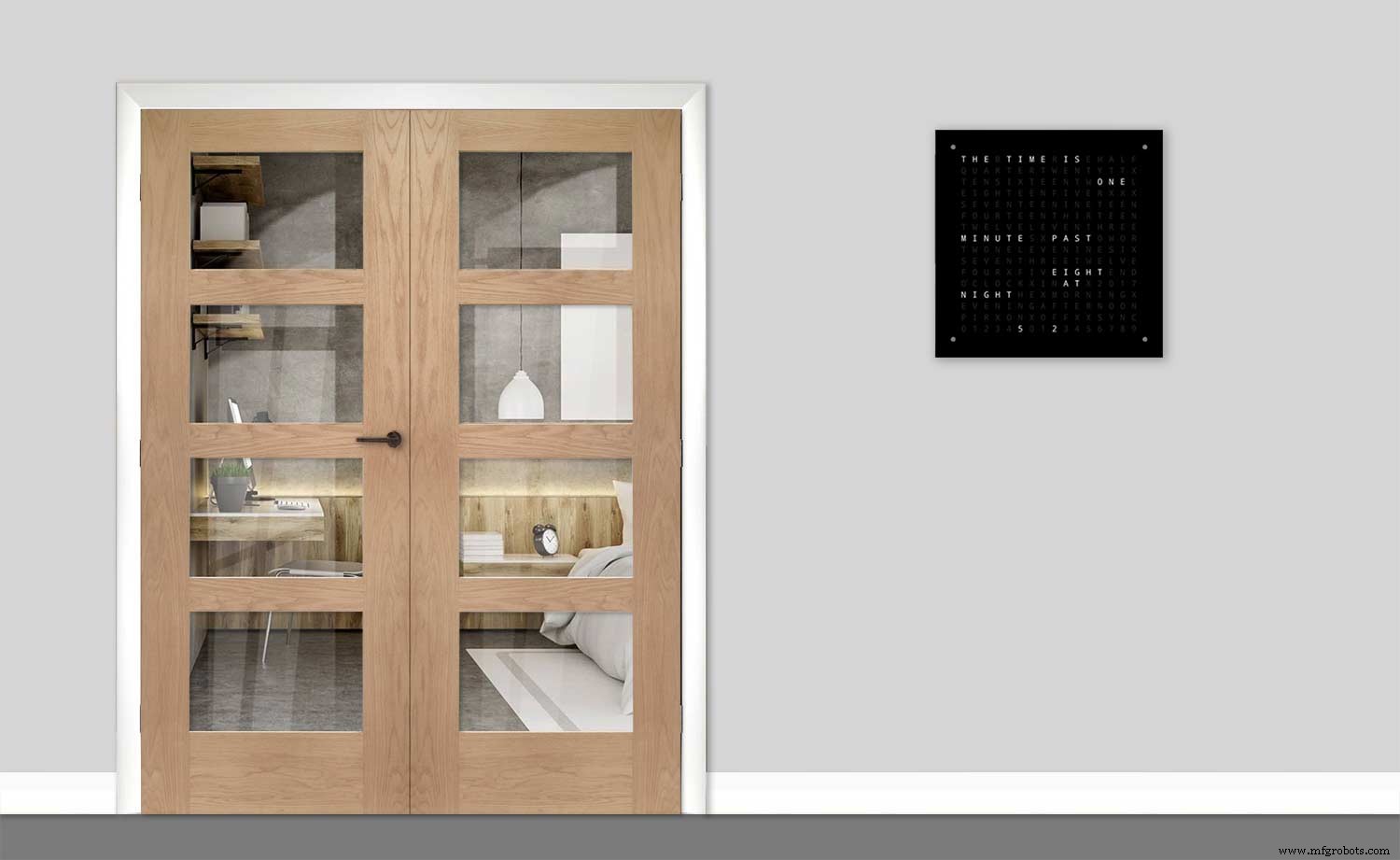
Step 26:PIR/Doppler Radar On Off Control
The PIR is turned on &off in word clock mode by touching the bottom left sensor to turn the PIR on or by touching the right sensor to turn the PIR off.
Note when the PIR is set to off the display stays on permanently.
<図>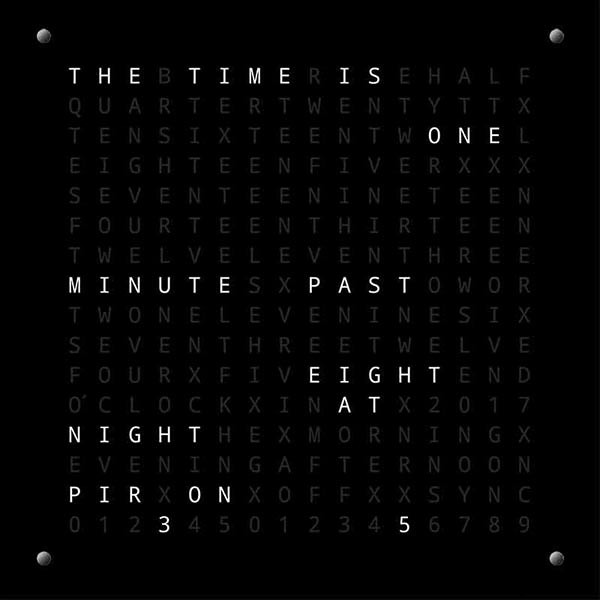
<図>

When you change the PIR setting the work "PIR ON" or "PIR OFF" is displayed for 5 seconds.
When initial power up the default is PIR off if you switch the PIR On straight away the display will go off as the PIR takes a minute or so to initialise before detecting movement.
Step 27:Setting Automatic Brightness Levels
The clock automatically senses the ambient light and adjusts the LEDs accordingly.
<図>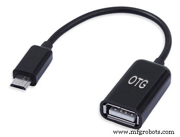
When first installed the clock will need to be calibrated to the maximum light levels in its actual location. Connect a mobile, laptop/tablet etc via a suitable cable to the mini USB port of the clock and open an app to monitor the serial port. I use Slick USB 2 Serial Terminal on my S7 via an OTG cable and USB to mini USB cable.
<図>
The clock will reboot and after the initial start screen you will see the following data updating down the screen.
You don't need to worry about lightReading or constrained lightReading+hyster just light reading, and bright.With the clock in position and the ambient light at its maximum levels carefully insert a flat bladed jewellers screwdriver into the access hole just to the right of the light sensor. Turn the screwdriver slowly until the light reading =600 (or your level set in brightness.cpp) and bright =15. Your clock will now go to max brightness when the ambient light is at its maximum. If you turn the screwdriver too far the light reading will go over 600 but the bright reading will not increase.
If you want the clock to be dimmer right across the range of ambient light levels adjust the light reading to a level less than 600 at max ambient light levels.
Note when bright=15 this will output the max current to the LEDs. The max current is set by R1( RSET) on the MAX7219 module and this should be chosen for your type of LED used in the display.
Step 28:Setting the Clock
The clock is set in the digital clock mode by touching the bottom left sensor.
<図>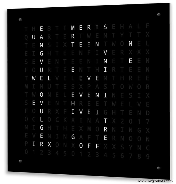
The hour digits will now flash twice a second to indicate the clock is in time setting mode.In this mode the sensors have the following functions.
Top right - steps the hours or mins digits up
Top left- steps the hours or mins digits down
Bottom left 1sr press - enters the time setting mode selecting hours digits
Bottom left 2nd press -selects the mins digits for changing
Bottom left 3rd press -exits time setting mode and sets the time
Bottom right - resets the seconds to 00
Step 29:Synchronisation
If you have connected a 30 second master clock sync cable then the clock will jump back or forward to 30 seconds when out of time setting mode. If you don't have a Master Clock to sync to then the clock will fall back on the on board temperature compensated real time clock which in itself is a very precise quartz clock.
Just reset the seconds roughly in sync to the seconds (within 10 seconds either way) and wait for the clock to sync once out of time setting mode.
<図>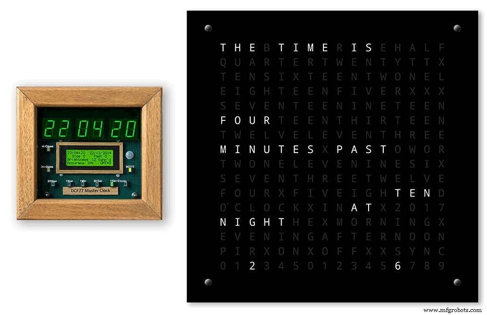
The animated loop below shows the Word Clock is running fast by several seconds. A synchronisation pulse is received from the Master Clock every 30 seconds on the minute and half minute synchronising the clock on 30 seconds.
The clock will ignore the 30 second synchronisation pulse from the Master Clock at 0 seconds. Note clock synchronisation only happens when the Word Clock is 20 seconds past and 20 seconds to a minute. In normal operation the sync pulse corrects the clock to within a fraction of a second so you will see the word "SYNC" appear with no visible correction to the seconds.
Note the synchronisation pulse is received every 30 seconds but the clock will ignore pulses at 0 seconds.
Step 30:Software &Making Changes
The software can be downloaded from the software tab and contains the following modules.
Program Files Modules
Brett_wordclock_v4_3.ino Main program, latest update includes shortened code saving 10% in size.
Thanks to srdevil for providing the updated code for this seconds display.
brightness.cpp/.h Brightness autoadjustment
character.cpp/.h Character (digit) definitions
credits.cpp/.h Ending Credits
display.cpp/.h Display &LED functions
life.cpp/.h Game of Life
serial.cpp/.h Serial port setup menu
simon.cpp/.h Simon Says game
temphum.cpp/.h Temperature &Humidity displa
tetris.cpp/.h Tetris game
time.cpp/.h Wordclock, digital clock
timeanalog.cpp/.h Analogue clock
touchbuttons.cpp/.h Touch buttons, mode switching
Third party libraries:
Chronodot.cpp/.h Chronodot library (for DS3231)
DHT.cpp/.h Temperature sensor library (for DHT22)
LedControl.cpp/.h LedControl library (for MAX7219)
stc.cpp/.h/platform.h Simple Tetris Clone library
pitches.h Note frequencies from the Arduino webpage
When you want to make changes to my code you can compare my code to the "Catalan Code" to make it easier to understand what changes you need to make. I have added //Brett to my code to highlight my changes.
Changing the code.
If like me you are not very good at coding just play around with the code to get an understanding of how it works.
I just save a different version each time I make even a tiny change. This way if I mess up I can go back a version and start again.
If you are keeping my linear seconds display update the version number on the display so you know what version you are trying out each time. This is done in the module credit.h around line 47.
It would take far too long to explain all the code but here is a very brief guide on how to change the words and when they are displayed.
The WORDS are set in time.h
<図>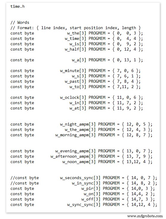
On line 52 we have
const byte w_the[3] PROGMEM ={ 0, 0, 3 };
The word "THE" is described in this line with the LED location in the curly brackets "{ 0, 0, 3 }"
This is the co-ordinate of the LEDs we are gong to light when we call "w_the"
The LED matrix numbers starts top left and start from 0 so "{ 0, 0, 3 }" is the first LED across and down the 3 just means the 3 LEDs across including this one will light. As the letters THE are in this position the word "THE" is displayed.
Similarly the word "TIME" would be lit by lighting the four LEDs here { 0, 4, 4 } or row 0, 5th LED along and light 4 LEDs (remember to count from 0).
Working you way down the page shows the position of all the words.
Controlling when words are lit
<図>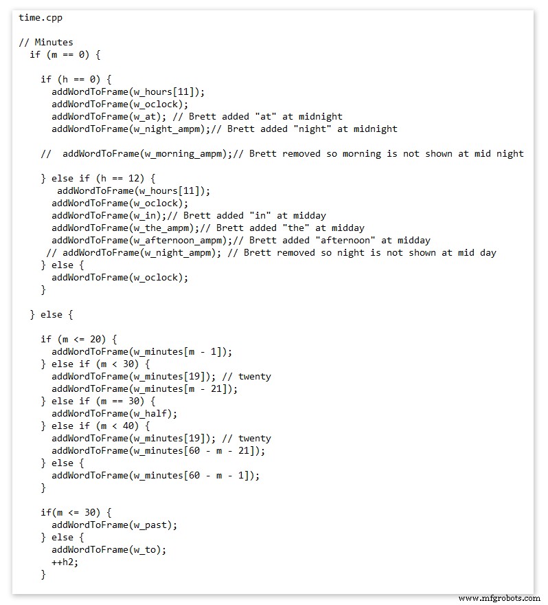
This happens in the module time.cpp
Here you just make a list of rules to tell the clock what words to light at certain times.
Pic above shows part of the code starting with line 695
At midnight we want to make the clock say "THE TIME IS TWELVE OCLOCK AT NIGHT"
Midnight is 00 00
"THE TIME IS" is always displayed from lines 687
So we add the rules if minutes are 0, then if hours are 0 show the word for hours "TWELVE" and the word "OCLOCK" the word "AT" and the word "NIGHT"
If you follow the code down all the possible time combinations are covered.
Analogue Clock Code Change - increase in time definition One of the comments sent to me by srdevil was some code changes. His comment can be seen below.
I have not had time to test the code but have included it below if you want to try it out.
" If the time is 18:00, it points up (long leg) and down (short leg). But when the time is 18:59, it still points totally down (short leg) so it looks like the time is 17:59 on a normal clock. My brother change the code so that if it is>HH:15 the small pointer moves already to the next number. As of this we also increased the resolution in the part between>HH:15 -
Code on the comments section or can be seen here http://home.btconnect.com/brettoliver1/Word_Clock/Word_Clock.htm#analogeclock
コード
- Brett_wordclock_v4_5.zip
Brett_wordclock_v4_5.zipArduino
Load into Aduino IDENo preview (download only).
Github
https://github.com/wouterdevinck/wordclockhttps://github.com/wouterdevinck/wordclockGithub
https://github.com/svcabre/wordclockhttps://github.com/svcabre/wordclockMy Word Clock on GITHUB
Schematics and code https://github.com/brettoliver/wordclock カスタムパーツとエンクロージャー
Vinyl Sticker Design in Inkscape (free to download) change as required brett11_print_ready_6bbpMTDyFa.svg 回路図
Schemaic showing main board connections 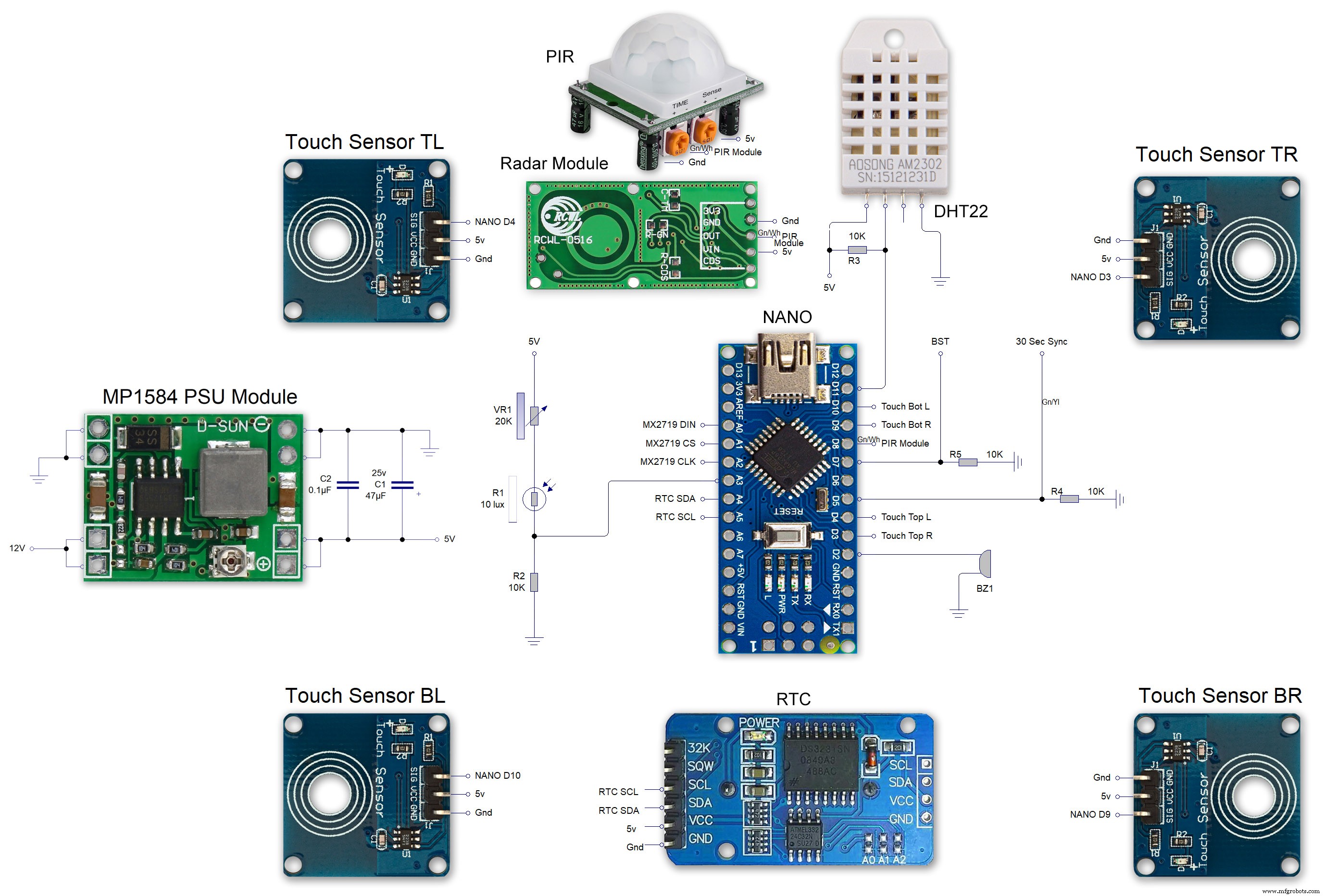 MAX7219 7 segment display module 01 LED connections
 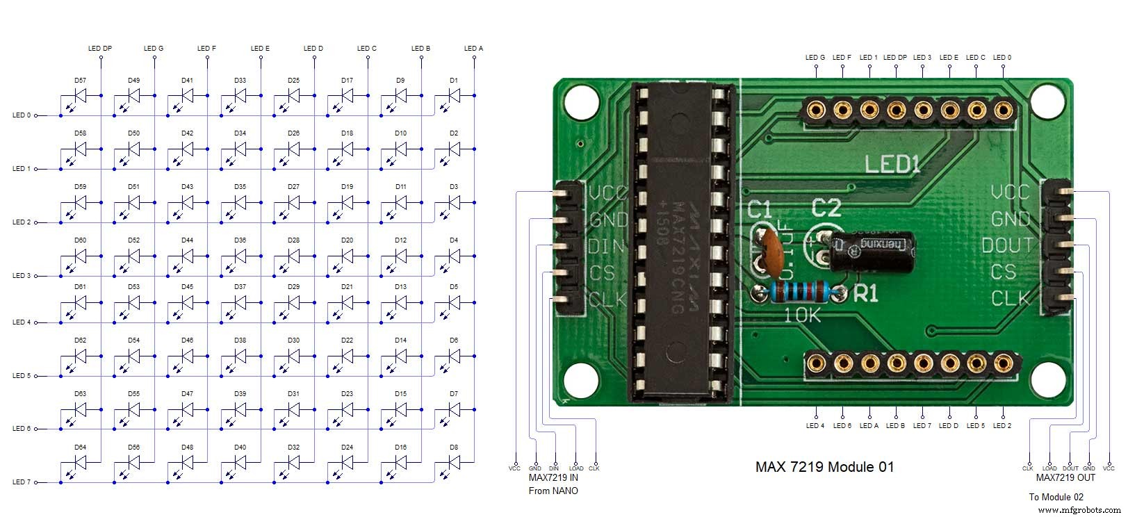 MAX7219 7 segment display module 02 LED connections
 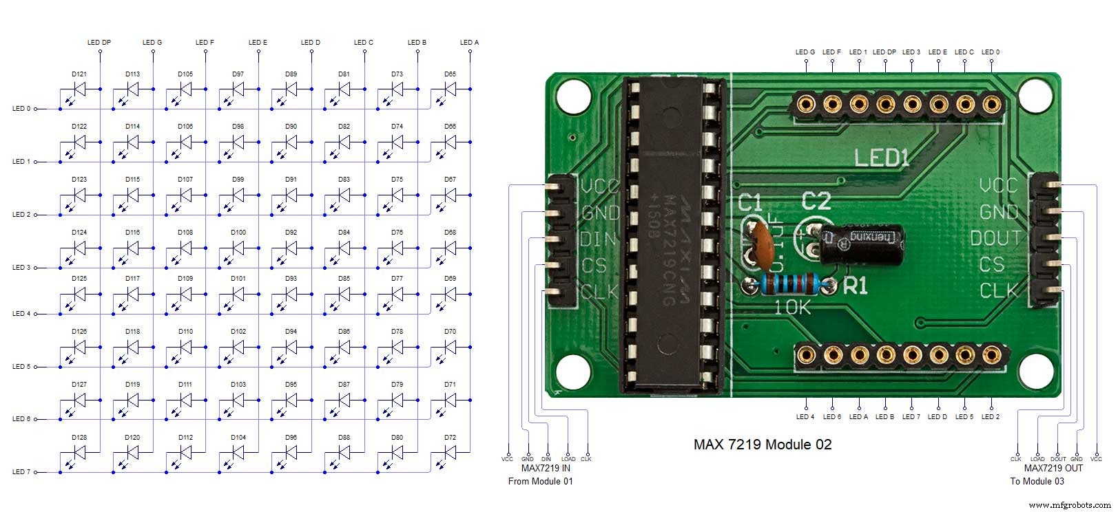 MAX7219 7 segment display module 03 LED connections
 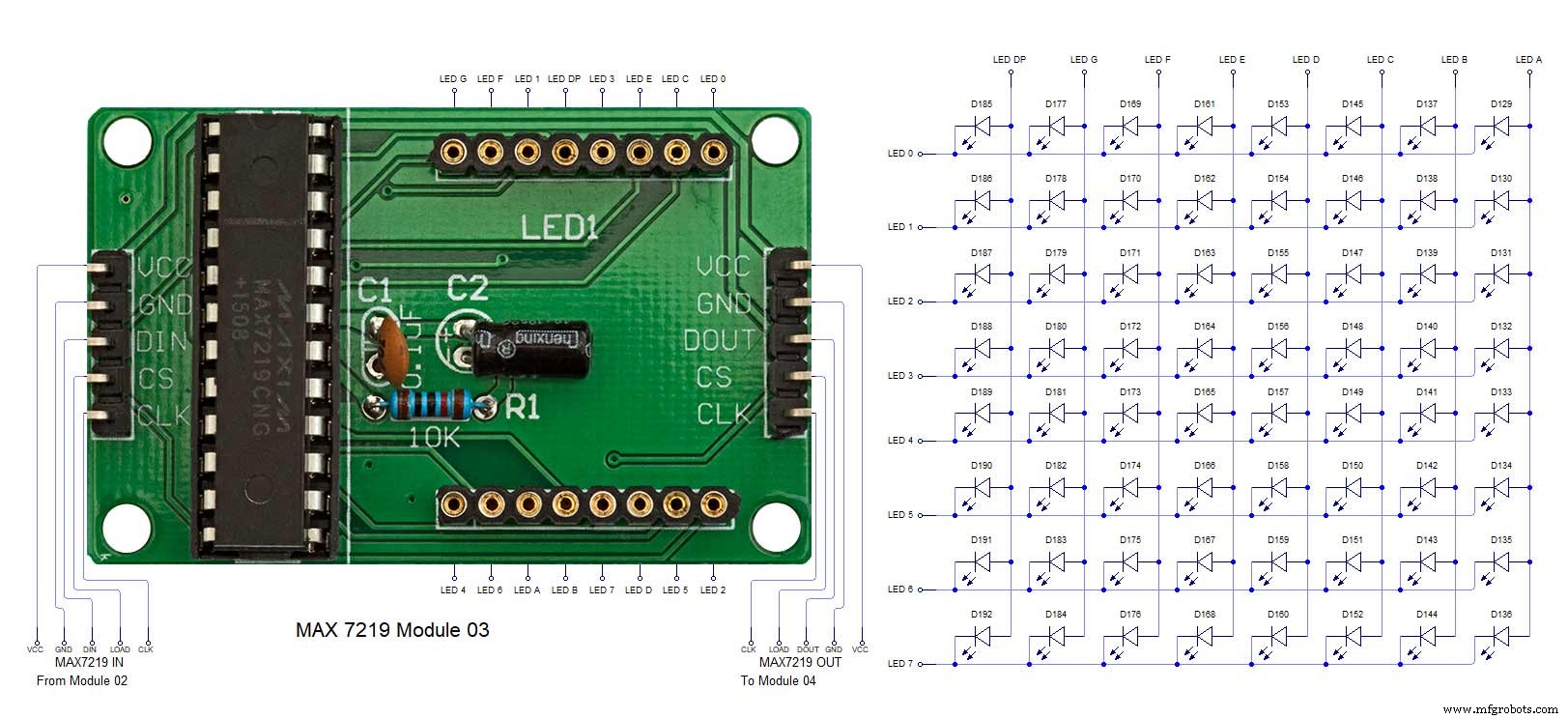 MAX7219 7 segment display module 04 LED connections
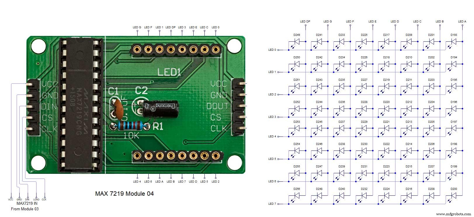
製造プロセス