



自作A4サイズ7セグメントディスプレイで作るArduinoビンゴマシン
必要な部品と材料
| ペグボード(7セグメントディスプレイ用2枚、スコアボード用1枚) | ×3 |
| カッティングボード(グレー、スコアボード用) | ×1 |
| デジタルLEDストリップ 5m WS2811(5050 LED、3LEDごとに1チップ) | ×1 |
| WS2812B LEDストリップ 5m(300LED、60LED/m、個別アドレス指定可能) | ×1 |
| オーディオケーブル(スコアボードと7セグメント間接続用) | ×1 |
| カッティングボード 半透明プラスチック(7セグメント表示面用) | ×2 |
| カッティングボード フレキシブルグレー(スコアボードカバー用) | ×1 |
| Arduino UNO | ×1 |
| 抵抗 220Ω | ×2 |
| コンデンサー 100μF | ×2 |
| 大型プッシュボタンスイッチ(モーメンタリー) | ×1 |
| 小型プッシュボタンスイッチ | ×1 |
| リニアレギュレーター 7805 | ×1 |
必要な工具と機械
- 一般的な工具とテスト機器(DIYプロジェクトで一般的に必要なもの)
プロジェクト概要
ACTIONストアで手頃な価格のデジタルLEDストリップ(12VアダプターとIRリモコン付きコントローラー込み)を見つけ、Arduino Unoで制御できないか実験開始。このストリップは3個の5050 LEDを1セグメントとし、WS2811ドライバー1個で制御するタイプでした。


Adafruit NeoPixelライブラリとサンプルコードで動作確認。7セグメント表示には7セグメント+小数点で8セグメント必要。これらを1本のArduino出力ピンで制御し、同梱の12Vアダプターで給電可能。
1桁だけでは用途が限られるため、2桁作ってビンゴマシンにしました。ボタンを押すと1-75の乱数を表示します。
ステップ1:7セグメントディスプレイの製作
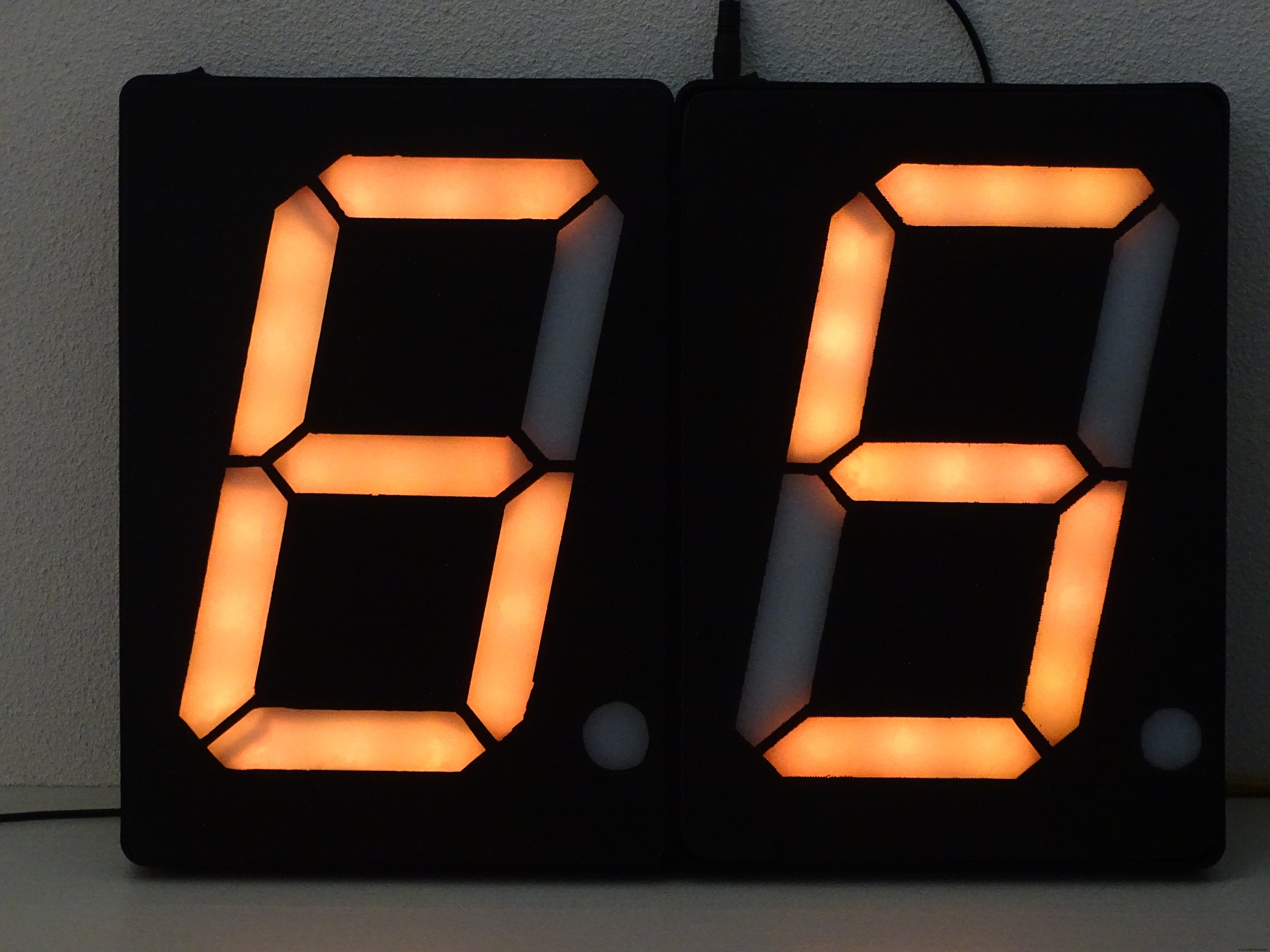
製作工程は長いため別チュートリアル向きですが、要約すると:
- レーザーカッターや3Dプリンターがあれば簡単だが、手作業でも挑戦的で楽しい
- 参考:Adafruit Ninja Timer、完成品購入も可能
- WS2811ストリップから3LED×16セグメントを切り出し使用
- セグメント間は+12V、GND、Do、Diをはんだ付けで接続
- ハウジングはACTIONのペグボードを使用
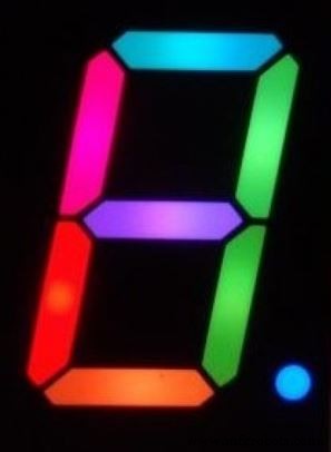
- 表示面はIKEAの白色半透明カッティングボードで自作。黒プライマー塗装上にテンプレートでセグメント形状を切り抜き
- 安価なオーディオケーブル(3線:12V、GND、Data in)でArduinoに接続(220Ω抵抗経由)
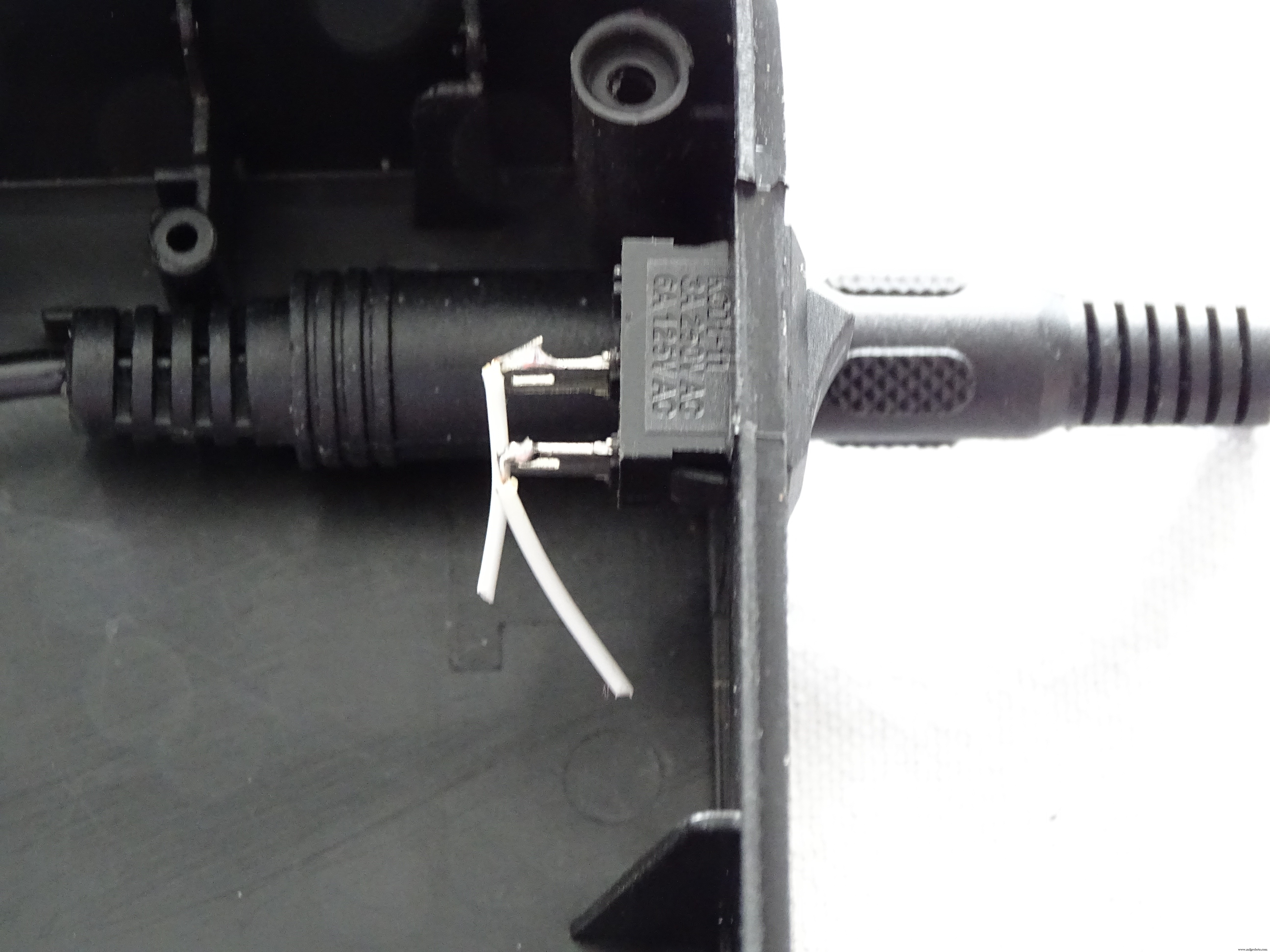
- オーディオコネクター着脱容易にハウジングを加工

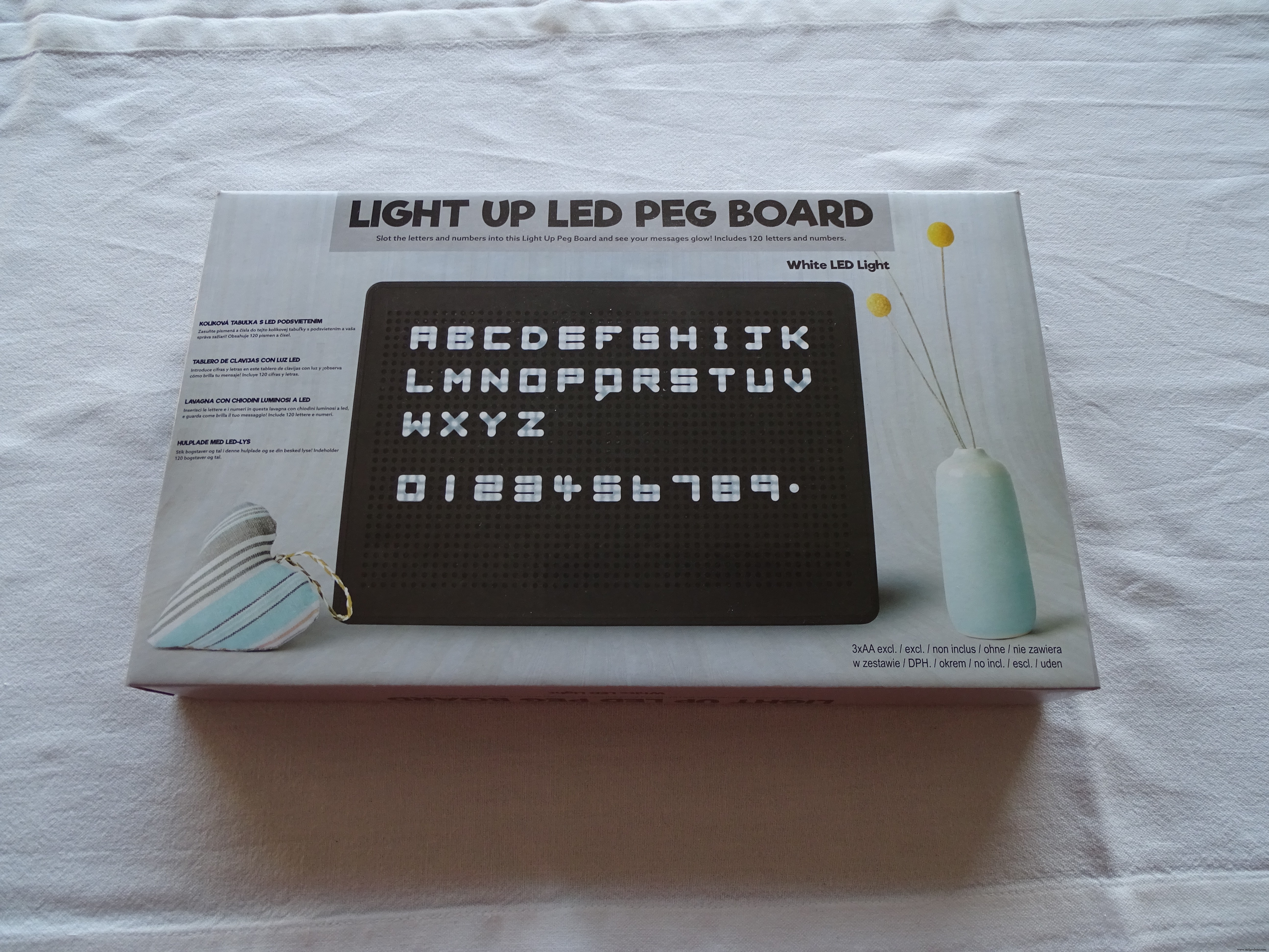
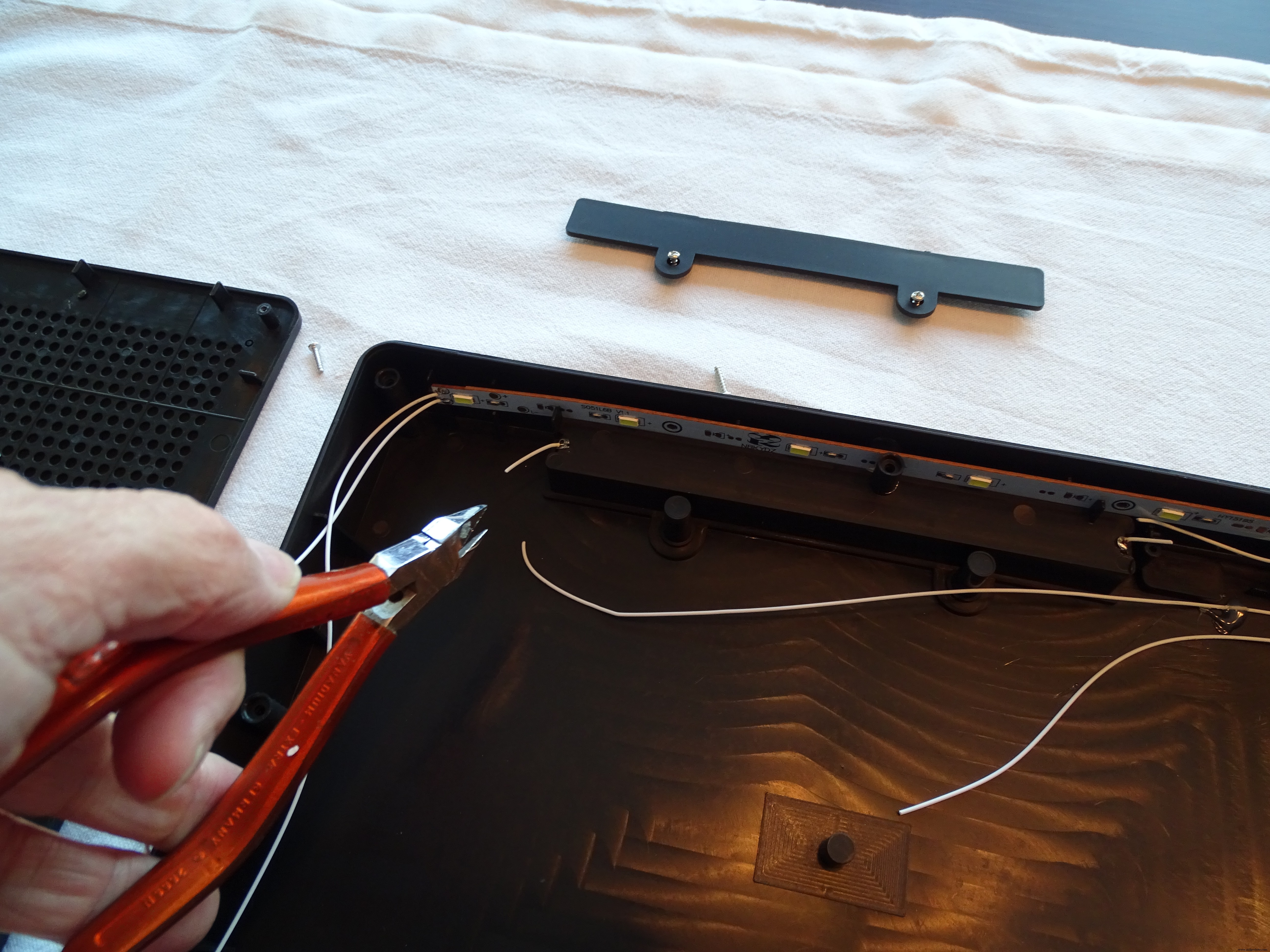

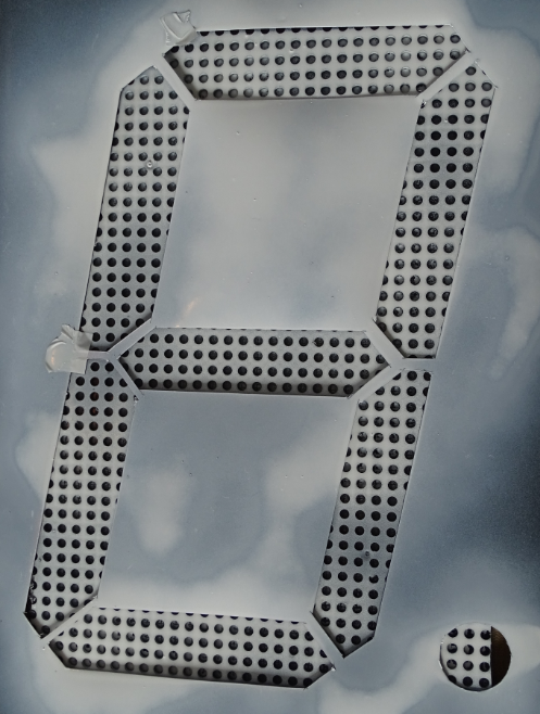


ステップ2:スコアボードの製作
生成された乱数履歴、新しい数字生成ボタン、ビンゴ終了/新ラウンド開始ボタンを備えたスコアボードも製作。
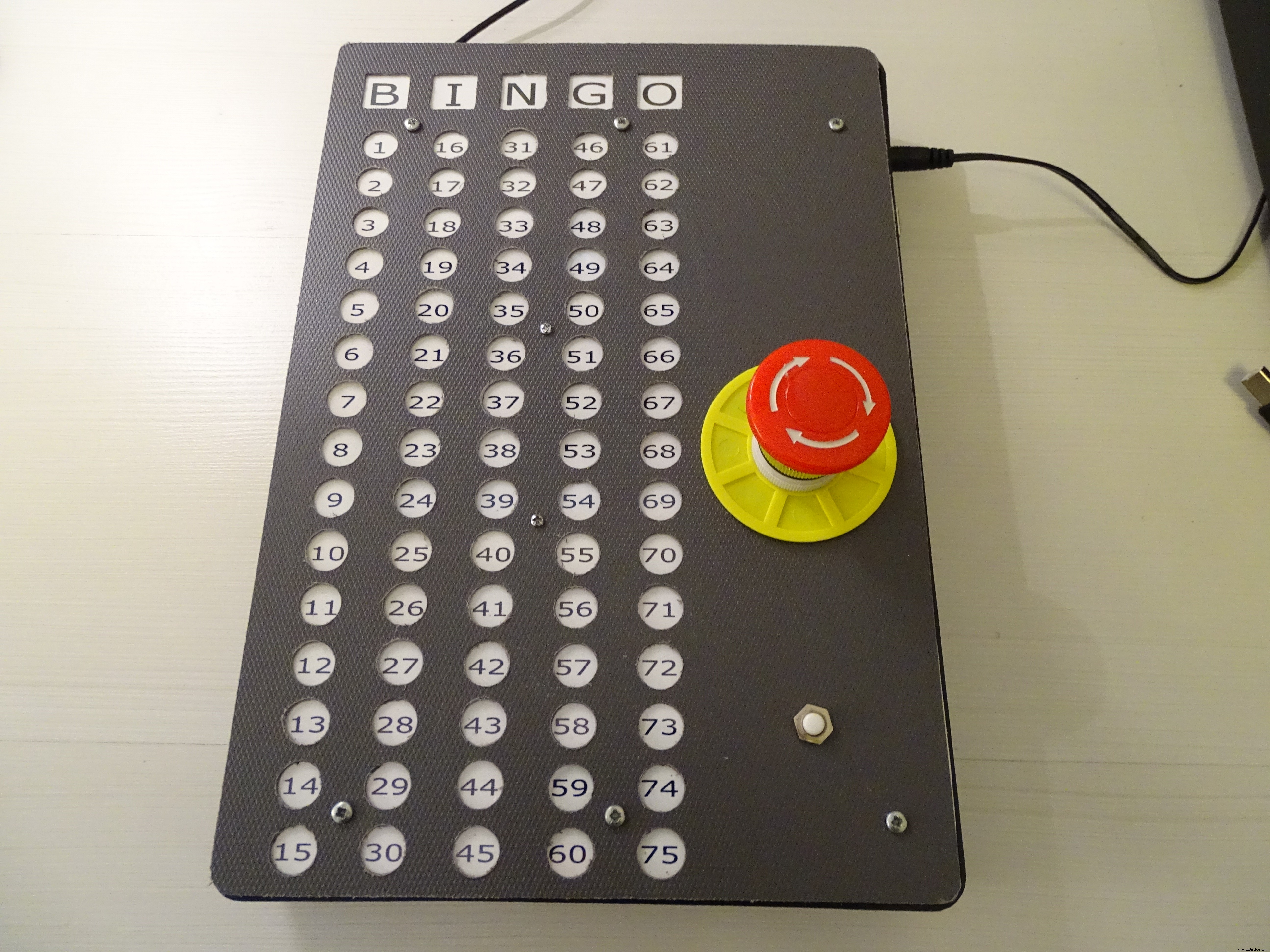
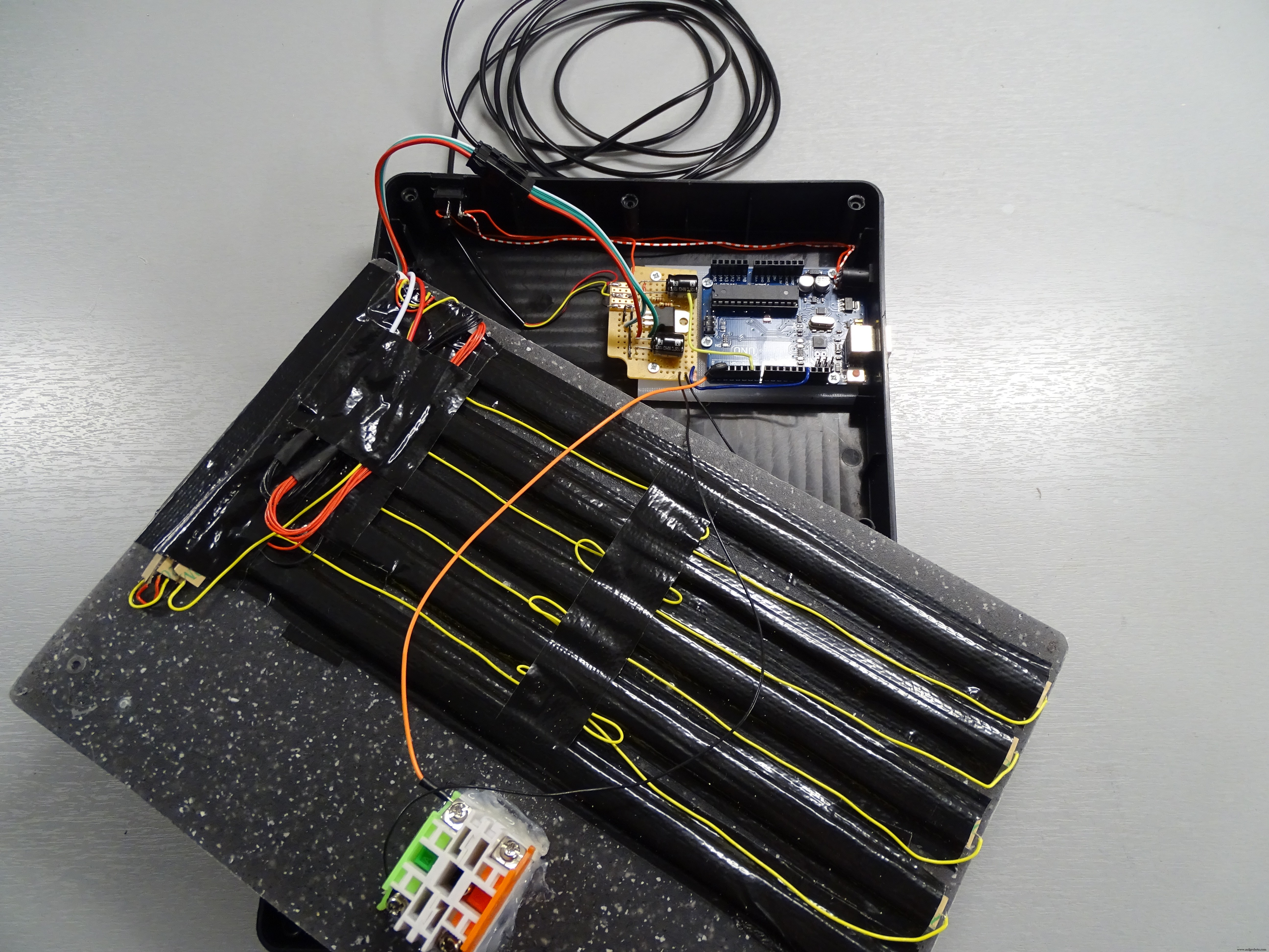
同じペグボードをハウジングに使用。カバーは濃灰色カッティングボード(穴あけ済み)、上面はIKEAカッティングボード。中間にフォト用紙印刷と保護フィルム。内部にはWS2812B LEDストリップ(15LED×5セクション)で数字1-75を表示、さらに8LED×3で「BINGO」文字をバックライト。
ステップ3:ソフトウェア開発
初期実験はブレッドボードで実施。
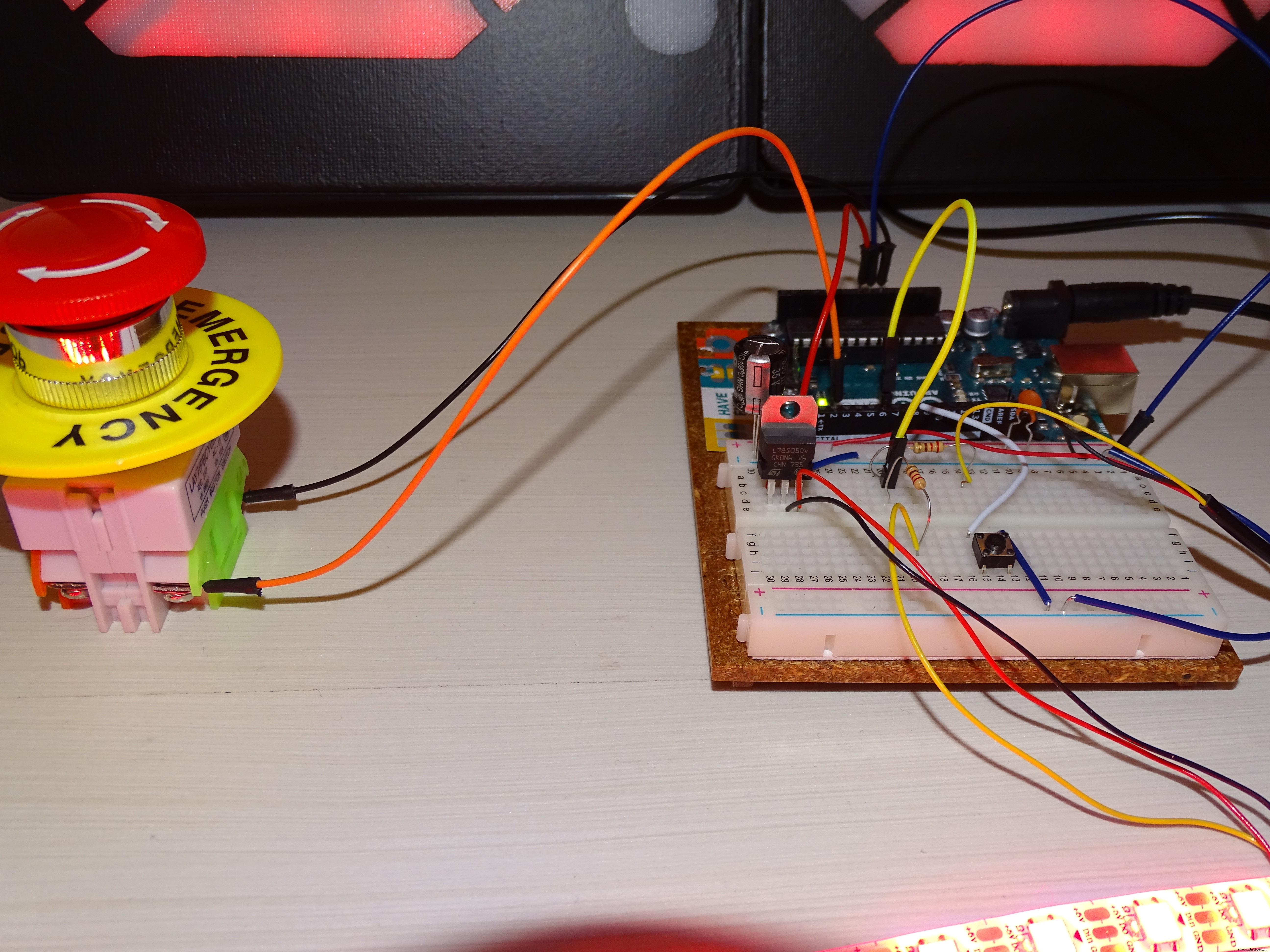
大型モーメンタリープッシュボタンをGNDとデジタルピン2に接続。押下で乱数生成開始。「ライトショー1」の後、2桁7セグメントに数字表示。
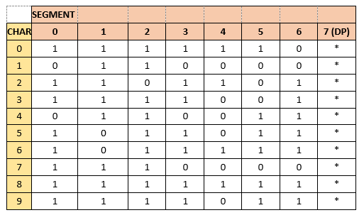
7セグメント表示用セグメント配置テーブル:

フローチャートで構造化(ClickCharts無料版使用)。
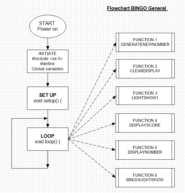
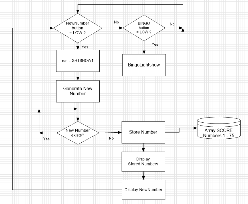
生成数字はSCORE[76]配列で管理(0=未出、1=出済み)。重複時は自動で再生成。スコアボードに点灯記録、7セグメントに現在数字表示。「BINGO」ボタンでラウンド終了(ライトショー後、配列クリア)。電源スイッチでリセットしても新ラウンド開始可能。
ステップ4:電子回路
12V 2Aアダプターで全体給電。Arduino電源ジャックを改造してスイッチ付きに。スコアボード用5V(99個のWS2812B:75数字+24バックライト)は7805レギュレーターで12Vから生成(ヒートシンク推奨。将来的にはパワートランジスタで強化予定)。スケッチ側で消費電力を抑制済み。
Fritzing回路図:
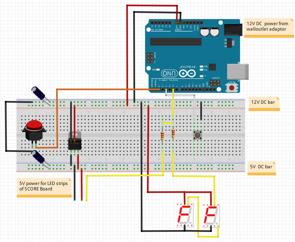
※7セグメント(12V駆動)とスコアボードLED(5V駆動)の両方を、Arduinoの同一出力ピン(D6)から220Ω抵抗経由で並列制御。
開発・製作:Pierre Pennings(2018年11月)
コード
BINGO_Machine_rev04.ino
/* This is the code for a Bingo Machine developed and produced by Pierre Pennings (November 2018) The machine uses 2 DIGIT large A4 sized 7-Segment displays made with WS2811 LED strip powered with 12V (pairs of 3 LEDs with 1 control chip) Each segment consisting of 3 LEDs is adressed with just one control adress Each display has 7 segments plus a decimal point (DP) The numbers presented on the 2 displays run from 1 to 75, just like in a normal BINGO game A momentary push button is connected to GND and to digital IO pin 6 of an ARDUINO UNO Pushing the button starts the generation of a New random Number After a short "Light Show 1" the random number is shown on the two 7-Segment displays The generated Number is also stored in an Array called SCORE[] consisting of 75 positions either filled with "0" or "1" If the generated New Number allready exist, automatically a new random number is generated All electronics including the ARDUINO UNO itself have been built in a separate Score Board Display The 75 numbers are lit with one WS2812B controller chips with one SMD5050 LED each (powered with 5 V) The Score Board shows all the random numbers generated until a valid BINGO is achieved A push button called "BINGO" will end the round with a short "BingoLightShow" Hereafter the SCORE array is cleared and a new round can be started A New Round can also be started by toggeling the power switch (disconnecting the 12V power) which will RESET the ARDUINO and restart the programme A 12V, 2A charger supplies the power to the complete BINGO machine The 12 V input on the ARDUINO power jack has been modified to enable power switching (on - off) The 5 V power for the 99 LEDs (75 + 24) used for the Score Board is derived from the 12V input power by means of a 7805 voltage regulator (which can nearly handle the current drawn by the WS2812 LED strip); installing a Heatsink or a power version is recommended This code is licensed under GPL3+ license. */ #include <Adafruit_NeoPixel.h> const int NewnumberButton = 2 ; // Digital IO pin 2 is connected to the Newnumber button with a normally open contact // Pin 2 will be driven with the built-in pull-up resistor to make it normally HIGH // The switch will pull the pin to ground momentarily. // On a high -> low transition by pushing the button the programme will generate a New Number. const int BingoButton = 4 ; // Digital IO pin 4 is connected to the BINGO button with a normally open contact // Pin 4 will be driven with the built-in pull-up resistor to make it normally HIGH // The BINGO Button will pull the pin to ground // On a high -> low transition by pushing the BINGO button a Lightshow will start and thereafter the programme will end. const int LedPin = 6 ; // Digital IO pin 6 connected to the Data In (DI) of the WS 2811 LED strips via a 220 Ohm resistor int Newnumber = 1; int Bingo = 1; int SCORE[76]; int count = 0; long randNumber; int NUMBER = 0; int NW_NUMBER = 0; int TENSNUMBER = 0; int UNITNUMBER = 0; #define NUM_LEDS 99 // the first 16 are used to control (WS 2811) the LED's in the 2 digit 7-segment displays //(two times 8 segments on the two displays); number 0 -7 are for the UNIT number // Number 8 - 15 are for the TENS number ( number 7 and 15 are the DPs of each DIGIT) // for displaying the numbers on the Score Board Display and controlling the (WS2812) LEDS the adresses 16 upto 99 are used // 24 LEDs are used for backlighting the letters BINGO and 75 for the score board to enable the display of the generated BINGO numbers; // all of the LEDs will be controlled with just one wire! from LED_PIN 6 // as a matter of fact two different types of LED strip are controlled (in parralel)from the same LedPin 6 via two 220 Ohm resistors #define BRIGHTNESS 250 // sets the brightness of the LEDs to allmost maximum (255) Adafruit_NeoPixel strip = Adafruit_NeoPixel(NUM_LEDS, LedPin, NEO_GRB + NEO_KHZ800); /*2-dimensional array with NUMBER to segment allocations, each NUMBER has its own colum---------------------------------------------------- 8 0 13 9 5 1 14 6 12 10 4 2 11 15 3 7 Digit 2 Digit 1 Tens Units 7 and 15 represent the Decimal Points (DP) */ // 0 1 2 3 4 5 6 7 8 9 byte SEGMENTarray [8][10] = { {1,0,1,1,0,1,1,1,1,1,}, //segment 0 or 8 {1,1,1,1,1,0,0,1,1,1,}, //segment 1 or 9 {1,1,0,1,1,1,1,1,1,1,}, //segment 2 or 10 {1,0,1,1,0,1,1,0,1,1,}, //segment 3 or 11 {1,0,1,0,0,0,1,0,1,0,}, //segment 4 or 12 {1,0,0,0,1,1,1,0,1,1,}, //segment 5 or 13 {0,0,1,1,1,1,1,0,1,1,}, //segment 6 or 14 {0,0,0,0,0,0,0,0,0,0,}, //segment 7 or 15 }; byte color_scheme[] = { 50, 100, 200, 100, 150, 250, 150, 200, 50, 200, 250, 100, 250, 50, 150, 0, 100, 200, 50, 150, 250, 100, 200, 0, 150, 250, 50, 200, 0, 100, 250, 50, 200, 0, 100, 250, 50, 150, 0, 250, 0, 0 }; /////////////////////////////////////////////////// the setup code that follows, will run once after "Power On" or after a RESET void setup() { Serial.begin(9600); pinMode(LedPin, OUTPUT); // initialize the LedPin 6 as an output: pinMode(NewnumberButton, INPUT_PULLUP); // initialize the pushbutton pin 2 as an input: pinMode(BingoButton, INPUT_PULLUP); // initialize the bingobutton pin 4 as an input: strip.setBrightness(BRIGHTNESS); strip.begin(); // Initialize all LEDs to "off" strip.show(); for (int t = 16; t < 24 ; t++) { strip.setPixelColor(t, 0, 0, 250); // After Power On show the word BINGO on the Score Board with Blue characters strip.show(); // note that the order of colors of the WS2812 LED strip is R,G,B } for (count = 0; count < 76 ; count++) { // put all data in the Array SCORE to 0 (Array positions run from 0 to 75; the zero position is not used) SCORE[count] = 0; } /*for (int n = 0; n < 10 ; n++) // this code can be used for testing all the numbers from 0 - 9 on the two 7-Segment displays (the 2 DP's are not tested) { for (int s = 0; s < 8 ; s++) { int z = SEGMENTarray [s][n]; int i = 0 + s; int j = 8 + s; strip.setPixelColor(i, z*250, 0, z*50); strip.setPixelColor(j, z*250, 0, z*50); strip.show(); Serial.print("["); Serial.print(n); Serial.print("]"); Serial.print("["); Serial.print(s); Serial.print("] = ");Serial.print(z); Serial.print(" "); } delay (1500); Serial.println(); } */ } /////////////////////////////////////////////////// the loop code that follows, will run repeatedly until "Power Off" or a RESET void loop() { Newnumber = digitalRead(NewnumberButton); if (Newnumber == LOW) // no need for a Short delay to eliminate bouncing effects of the button because at first LOW the loop proceeds { randomSeed(millis()); do { GENERATENEWNUMBER (75); // generate a NW_NUMBER between in the range from 1 to 75 } // if the NW_NUMBER allready exists: generate again a NW_NUMBER while (NW_NUMBER == SCORE[NW_NUMBER] * NW_NUMBER); SCORE[NW_NUMBER] = 1; // put a 1 in the Array at the NW_NUMBER position NUMBER = NW_NUMBER; TENSNUMBER = int (NUMBER / 10); // calculate the decimal value of the NW_NUMBER and the unit value UNITNUMBER = NW_NUMBER - (10 * TENSNUMBER); CLEARDISPLAY (); LIGHTSHOW1 (4, 100); // start lightshow1 CLEARDISPLAY (); //PRINTNUMBERSERIAL(); // print the generated NW_NUMBER to the serial monitor and show the new content of the SCORE array DISPLAYNUMBER (TENSNUMBER, UNITNUMBER); DISPLAYSCORE (); } else { Bingo = digitalRead(BingoButton); if (Bingo == LOW) delay (3000); // a delay of 3 second to eliminate bouncing effects and accidental pushing of the button because if (Bingo == LOW) { BINGOLIGHTSHOW (); for (count = 0; count < 76 ; count++) // put all data in the Array SCORE back to 0 and a new BINGO round can be started { SCORE[count] = 0; } } } } //////////////////END of LOOP//////////////////////////////////////////////////////////// /////////////////////////////////////////////////// Hereafter follow the specific Functions that are called from within the loop void LIGHTSHOW1 (int duration, uint8_t wait) { for (int t = 16; t < 24 ; t++) { strip.setPixelColor(t, 0, 0, 0); // turn off the BINGO Leds with Blue characters as put upon set up strip.show(); } for (int k = 0; k < duration; k++) { // flash the DP leds in a white color strip.setPixelColor(7, 200, 200, 200); strip.show(); delay(wait); strip.setPixelColor(7, 0, 0, 0); strip.setPixelColor(15, 200, 200, 200); strip.show(); delay(wait); strip.setPixelColor(15, 0, 0, 0); } int redVal, blueVal, greenVal; for (int k = 1; k < 45 ; k = k + 3) { // run a rainbow color lightshow with colors defined in the Array color_scheme redVal = color_scheme[k]; blueVal = color_scheme[k + 1]; greenVal = color_scheme[k + 2]; for (int p = 0; p < 7; p++) { // the collors of the WS2811 strip are adressed in the order R, B, G int i = 0 + p; int j = 8 + p; strip.setPixelColor(i, strip.Color(redVal, blueVal, greenVal) ); strip.setPixelColor(j, strip.Color(greenVal, redVal, blueVal ) ); strip.show(); delay(30); } } for (int q = 0; q < 7 ; q++) { // put all segments of the 7-segment displays to "off" int i = 0 + q; int j = 8 + q; strip.setPixelColor(i, 0, 0, 0); strip.setPixelColor(j, 0, 0, 0); strip.show(); } } /////////////////////////////////////////////////Hereafter follows the function for generating the BINGO LIGHTSHOW after the Bingo Button is pushed void BINGOLIGHTSHOW () { for (int l = 0; l<10; l++) { for (int k = 24; k < 39 ; k++) // present a waterfall of white leds on the SCORE board { strip.setPixelColor(k, 200, 200, 200); strip.setPixelColor(k+15, 200, 200, 200); strip.setPixelColor(k+30, 200, 200, 200); strip.setPixelColor(k+45, 200, 200, 200); strip.setPixelColor(k+60, 200, 200, 200); strip.show(); delay(5); strip.setPixelColor(k, 0, 0, 0); strip.setPixelColor(k+15, 0, 0, 0); strip.setPixelColor(k+30, 0, 0, 0); strip.setPixelColor(k+45, 0, 0, 0); strip.setPixelColor(k+60, 0, 0, 0); strip.show(); } for (int t = 0; t < 24 ; t++) { strip.setPixelColor(t, 0, 250, 250); // turn on the 7-segment displays and BINGO Leds strip.show(); } delay(50); for (int t = 0; t < 24 ; t++) { strip.setPixelColor(t, 0, 0, 0); // turn off the 7-segment displays and BINGO Leds strip.show(); } } } /////////////////////////////////////////////////// Hereafter follows the function for generating a new number after the New Number Button is pushed void GENERATENEWNUMBER (int range) { randNumber = random(1, range + 1); NW_NUMBER = int(randNumber); } /* ////////////////////////////////////////////////// This function can be used to present the generated NUMBER and show the modified contents of the SCORE array void PRINTNUMBERSERIAL () { Serial.print("NUMBER = "); Serial.print(NUMBER); Serial.print(" , TENSNUMBER = "); Serial.print(TENSNUMBER); Serial.print(" , UNITNUMBER = "); Serial.println(UNITNUMBER); count = 1; while (count < 76) { // print all data in the Array SCORE (Array positions from 0 to 75; the zero position remains 0) for (int column = 0; column < 15; column++) { Serial.print("["); Serial.print(count); Serial.print("] = "); Serial.print(SCORE[count]); Serial.print(" "); count++; } Serial.println(""); } } */ ///////////////////////////////////////////////// This function is used to display the generated NUMBER on the two 7-Segments displays void DISPLAYNUMBER (int TENS, int UNIT) { for (int t = 16; t < 24 ; t++) { strip.setPixelColor(t, 200, 0, 0); // turn on the BINGO word Leds in RED characters strip.show(); } for (int s = 0; s < 8 ; s++) { // take the data from the SEGMENT array to turn on correct segments for displaying the UNITS and TENS of the NUMBER in RED int t = SEGMENTarray [s][TENS]; int u = SEGMENTarray [s][UNIT]; int i = 0 + s; int j = 8 + s; strip.setPixelColor(i, u*250, 0, 0); if (TENS!=0) { strip.setPixelColor(j, t*250, 0, 0); } else { strip.setPixelColor(j, 0, 0, 0); } strip.show(); } } ///////////////////////////////////////////////// This function is used to display the generated NUMBER on the two 7-Segments displays void DISPLAYSCORE () { for (int t = 16; t < 24 ; t++) { strip.setPixelColor(t, 200, 0, 0); // turn on the BINGO word Leds in RED characters strip.show(); } for (int s = 24; s < 100 ; s++) { // turn on the LEDs for the existing Numbers in GREEN int u = SCORE[s-23]; strip.setPixelColor(s, 0, u*200, 0); strip.show(); } strip.setPixelColor((23+NUMBER), 200, 0, 0); // turn on the LEDs for the new Number in RED strip.show(); } ///////////////////////////////////////////////// This function is used to clear the two 7-Segments displays void CLEARDISPLAY () { for (int q = 0; q < 7 ; q++) { int i = 0 + q; int j = 8 + q; strip.setPixelColor(i, 0, 0, 0); strip.setPixelColor(j, 0, 0, 0); strip.show(); } for (int t = 16; t < 24 ; t++) { strip.setPixelColor(t, 0, 0, 0); // turn off the RED characters of the BINGO word strip.show(); } }
カスタムパーツとエンクロージャー
- tekening_gaten_patroon_puntjes_xgW76A8Jmw.svg(ディスプレイ前面用テンプレート)
回路図
bingo_sketch_66WRdQITE2.fzz
製造プロセス
- 自宅で作るDIY宿題自動筆記マシン:AxiDraw風ペンプロッターの自作ガイド
- Arduinoで作るレトロNumitron管時計:シンプル、信頼性高く、省エネ
- ArduinoとNokia 5110ディスプレイで自作電圧計:ステップバイステップガイド
- Arduino Nanoとロータリーエンコーダーで作る高精度測定ホイール
- シャープGP2Y1010AU0Fセンサーで作る高精度空気質モニター
- Arduino NanoとWS2812 LEDストリップで作る1次元ポンゲーム - 完全DIYガイド
- Arduino Nano R3で本格的なCNCマシンを自作する
- Arduino搭載HID UPS:ダミー電源をUSB対応バックアップにアップグレード
- Arduinoで作るポータブルRFIDドアロック - ステップバイステップガイド
- Arduino Nanoで作るBluetooth対応スマートコーヒーメーカー 〜温度グラフ表示と自動開始機能付き〜
- Arduino Nanoで作る高感度金属探知機 — 鉄/非鉄金属の識別機能付き