


ESP8266-01とArduinoを使用したIoT
コンポーネントと消耗品
>  |
| × | 1 | |||
 |
| × | 1 | |||
 |
| × | 1 | |||
| × | 1 | ||||
 |
| × | 2 | |||
 |
| × | 1 | |||
 |
| × | 1 | |||
 |
| × | 2 | |||
 |
| × | 1 |
必要なツールとマシン
| > |
| |||
 |
| |||
 |
|
アプリとオンラインサービス
| ||||
 |
| |||
|
このプロジェクトについて
はじめに
今日は、インターネットに接続し、ユーザーがWi-Fi経由で自宅をリモートで制御できるようにするデバイスを構築します。このデバイスを作成するために、ESP8266-01 Wi-FiモジュールでArduinoボード(どのモデルでもうまく機能します)を使用します。始めましょう!
スマートホームとは何ですか?
作業シナリオ <図>

ControlPanel
ユーザーがシステムに接続されている家電製品を制御できるようにするためのコントロールパネルとして機能する簡単なWebページを作成します。 Webページを作成するには、次を使用します:
- HTML
- CSS
- Jquery
組み込みハードウェア
Webページは、Arduinoボードに接続されたWebサーバーとして機能しているESP8266-01にいくつかの注文を送信します。そして、入ってくるデータによると、Arduinoボードは電球をオンにする、テレビをオフにするなどのいくつかのアクションを実行します。この部分では、以下を使用します:
- Arduino
- ESP8266-01
ESP8266-01入門
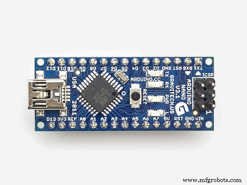
前に述べたように、インターネットに接続するにはArduinoボードが必要ですが、現在使用しているバージョンのArduinoNanoにはその機能がありません。そこで、ESP8266-01 Wi-Fiモジュールを使用して、Wi-Fi機能を小さなArduinoボードに追加します。
そこにはたくさんのESPwifiモジュールモデルがありますが、どれを選ぶべきですか?!まあ、そこにあるほとんどすべてのESPファミリーwifiモジュールはうまく機能しますが、それぞれに独自の機能と仕様があります。それぞれの仕様と機能を確認して、ニーズに最も適したものを選択することをお勧めします。
<図>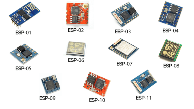
私のニーズに応じて、ESP8266-01が最適であることがわかりました。これには、さまざまな理由があります。メーカーコミュニティでは非常に有名です。その結果、この素晴らしい小さなモジュールで直面するほとんどすべての質問や問題に対する答えを見つけることができる非常に堅実なオンラインコミュニティを手に入れました。また、その価格は非常に安いです(約1.5ドル)。
また、シリアル通信を介してArduinoボードと通信できるシリアルwifiモジュールであるため、Arduinoボードでの使用は非常に簡単です。マイクロコントローラーが内蔵されているため、スタンドアロンのマイクロコントローラーとWi-Fiモジュールを1つのコンボで使用できます。これは非常に優れています。 2つのGPIOが組み込まれています。 1.5ドルで、実際には非常にクールなこれらの機能をすべて利用できます。このモジュールを詳しく見てみましょう。
ESP8266-01ピン配置 <図>
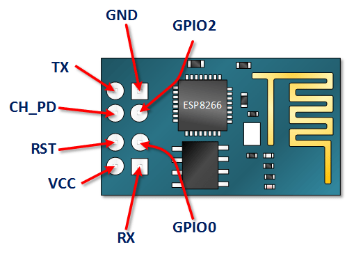
- VCC: + 3.3V電源に接続します。 損傷する5Vソースに接続しないでください 。
- GND: -veピン、回路のアースに接続します。
- CH_PD: チップはピンを有効にします–アクティブHIGH。モジュールを起動できるように、論理値HIGHに接続します。
- RST: チップリセットピン–アクティブLOW、LOWに引っ張ると、モジュールをリセットします。
- GPIO0、GPIO2: 汎用入力/出力ピン。
- 送信: マイクロコントローラー(Arduino)のRxに接続して、シリアル通信を確立します。
- Rx: マイクロコントローラー(Arduino)のTxに接続して、シリアル通信を確立します。
ESP8266-01構成
前に述べたように、ESP8266-01モジュールはシリアル通信を介してArduinoボードと通信します。つまり、Arduinoのシリアルピン0、1(Tx、Rx)に接続する必要があります。ただし、ここでの問題は、デバッグ目的でESP8266-01と一緒にArduinoシリアルモニターを使用するため、これらのピンがビジーになることです。したがって、ESP8266-01で使用するには、さらに2つのシリアル通信ピンを見つける必要があります。
幸い、Arduinoはこれを簡単にしました。 「SoftwareSerial」と呼ばれるライブラリがあります。これは、ソフトウェアを使用して機能を複製し、Arduinoの他のデジタルピンでシリアル通信を可能にするために開発されました。たとえば、このライブラリを使用することで、ピン2、3(SoftwareSerial)をピン0、1(ハードウェアシリアル)と一緒にRxおよびTxとして設定できます。
「SoftwareSerial」 ライブラリは、伝送速度が19、200ボー未満である限りうまく機能します。しかし、ここには小さな問題があります。 ESP8266-01 Wi-Fiモジュールは、速度115、200ボーで通信するようにプログラムされた工場出荷時に提供されます。これは、「SoftwareSerial」ライブラリでは通信が困難です。そのため、wifiモジュールを再プログラムして、通信速度を9600ボーに設定する必要があります。これは、「SoftwareSerial」ライブラリで非常にうまく機能します。そのために、いくつかの「ATコマンド」を使用します。
ESP8266-01通信速度の変更
最初のステップ:空のプログラムをArduinoボードにアップロードします
<図>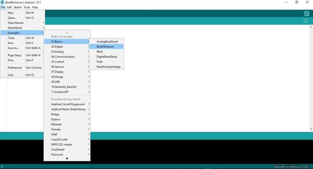
このステップでは、空のコードをArduinoボードにアップロードしています。 Arduinoボードによってバックグラウンドで実行されているものがないことを確認してください。
2番目のステップ:ArduinoボードでESP8266-01を配線する
<図>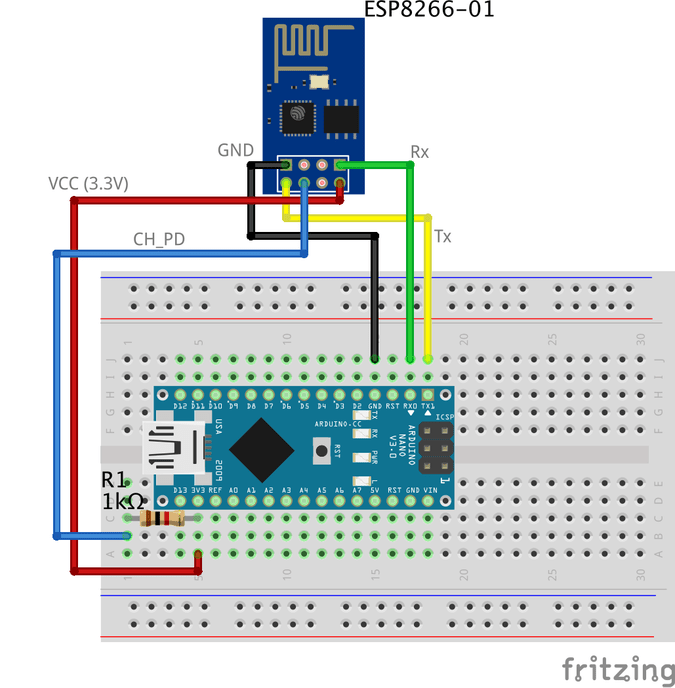
ESP8266-01を再構成し、通信速度(ボーレート)を変更するには、ATコマンドを使用します。簡単に言うと、ATコマンドは、モデム、携帯電話、Bluetoothモジュール、wifiモジュール、GSMモジュールを制御するために使用されるいくつかの命令です。
これらのコマンドを使用すると、製造元の名前、モデル番号、IMEIなどの携帯電話またはGSMモジュールに関する基本情報を取得できます。「AT」は「ATtention」の略語であり、すべてのコマンドが開始されるため、ATコマンドと呼ばれます。 「AT」付き。 「AT」プレフィックスはコマンド自体の一部ではなく、モジュールにコマンドの開始を通知するだけです。
いくつかの重要なATコマンド <図>
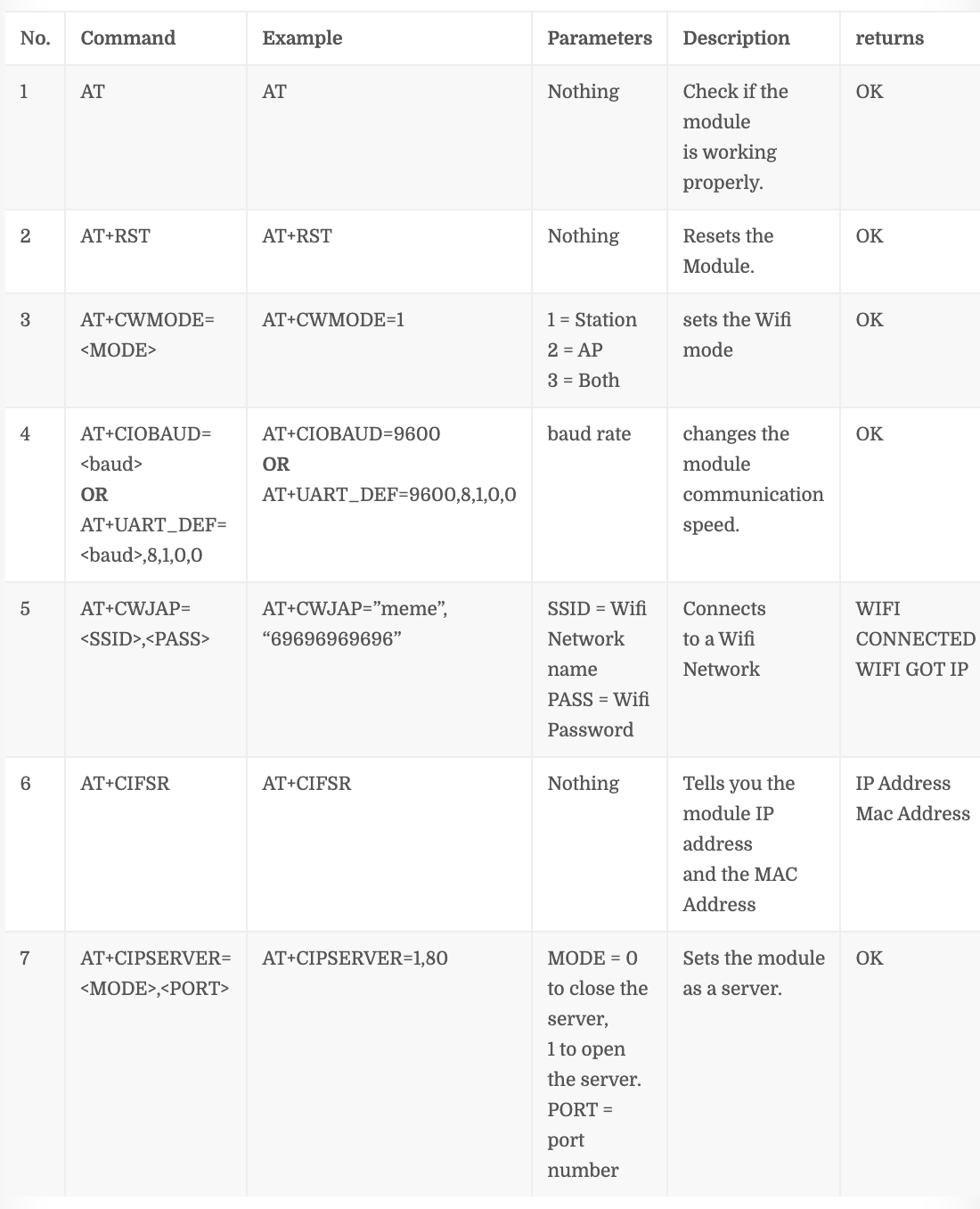
コマンド番号「4」 このコマンドが機能しない場合は、ESP8266-01ファームウェアのバージョンによって異なります AT + CIOBAUD = これを試してください AT + UART_DEF =
ステップ1:シリアルモニターを開く
<図>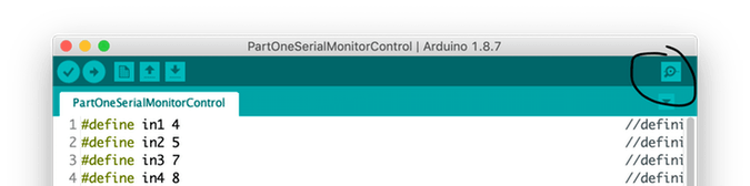
ステップ2:通信速度を115、200ボーに設定します
<図>
前に述べたように、ESPは、速度115、200ボーで通信するようにプログラムされたメーカーから提供されます。したがって、Arduinoの通信速度を 115、200 に設定する必要があります 初めての場合も、後で変更します。また、「NLとCRの両方」を選択する必要があります 。
ステップ3:「AT」を送信し、応答を待って、ESPモジュールがあなたの声を聞いていることを確認します。
<図>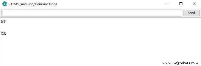
ステップ4:ここで、ESP8266-01の通信速度を変更します
<図>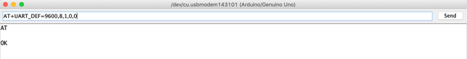
私のESP8266-01モジュールにロードされたファームウェアは1.6です。このコマンドは AT + UART_DEF = 私にとってはうまくいきます。うまくいかない場合は、この AT + CIOBAUD =を試してください 。 「OK」で応答した場合 これで、ESPモジュールの通信ボーレートが 115、200 から変更されました 9600 へのボー ボー。おめでとうございます!
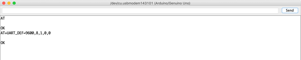
シリアルモニターの通信速度を9600に戻し、「AT」を再度送信して、ESPモジュールが新しい速度(9600)で私たちの声を聞くことができるかどうかを確認しましょう。
<図>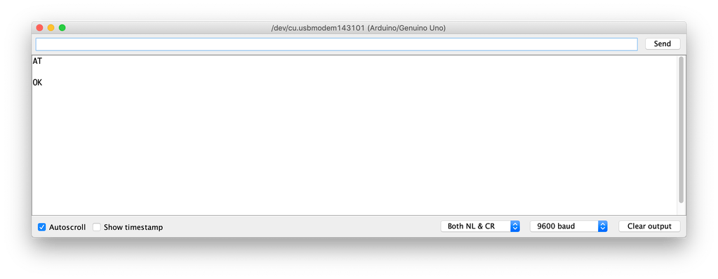
見る!動作しています。 ESP8266-01は、115、200ボーレートではなく9600ボーレートでArduinoボードと通信できるようになりました。
それでは、Wifiネットワークに接続してみましょう
<図>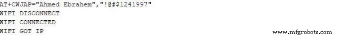
Enterキーを押すと、ESP8266-01はこのネットワークを検索して接続します。プロセスが成功すると、これが返されます
WIFI CONNECTED
WIFI GOT IP
この時点で、ESP8266-01の通信速度を115、200ボーから9600ボーに変更することに成功しました。次に、ユーザーが家電製品を制御するために使用するコントロールパネル(Webページ)を作成する必要があります。それでは、作成しましょう!
インターネットとは何ですか?
実際、インターネットは地下に埋められたワイヤーであり、光ファイバー、銅線、さらには衛星でもかまいませんが、インターネットは単なるワイヤーであり、そのワイヤーに接続された2台のコンピューターは通信できます。コンピューターが直接接続されている場合 そのワイヤーにそれはサーバーと呼ばれます そのワイヤーに直接接続されていない場合は、クライアントと呼ばれます 。
サーバー: Apacheのような特定のオペレーティングシステムを実行する特別なコンピュータです。この特別なコンピュータは、ディスクドライブにいくつかのWebページ、ファイル、データベースを保存します。インターネットに接続されているサーバーには、 172.217.171.228 のような一意のIPアドレスがあります。 、IPアドレスは、電話番号が人々がお互いを簡単に見つけるのに役立つのと同じです。そのIPアドレスは、人間が覚えるのは簡単ではないためです。そこで、 google.com という名前を付けました。 (ドメイン名)。
クライアント: それはあなたと私が毎日使用しているようなコンピューターであり、インターネットサービスプロバイダー(ISP)を介してインターネットに間接的に接続されており、一意のIPアドレスも持っています。
作業シナリオ
簡単に言うと、Google Chrome、Firefoxなどのウェブブラウザ(クライアント)から送信されたリクエストで始まり、ウェブサーバーから受信したレスポンスで終わります。
コンピューター(クライアント)からブラウザーにWebサイトのURL makesomestuff.orgを入力すると、このブラウザーはWebサイトをホストするWebサーバーに要求を送信し、WebサーバーはHTMLページまたはその他のドキュメント形式を含む応答をブラウザーに返します。
まさに、それが私たちのプロジェクトで今日行う必要があることです。 Webブラウザ(クライアント)からESP8266-01(Webサーバー)にリクエストを送信する必要があります。ESP8266-01(Webサーバー)は両方とも同じローカルネットワークに接続されています。このリクエストには、Arduinoに電球をオンまたはオフにする方法を指示するデータが含まれています。それでは、Webページを作成しましょう!
Webページの構築
Webページを作成するには、HTML、CSS、Javascriptを処理する必要があります。これらの名前について聞いたことがない場合でも、心配しないでください。
HTML: 「ハイパーテキストマークアップ言語」の略で、Webページのメイン構造を構築するために使用します。いくつかのボタン、画像、段落、ヘッダー、表、その他多くの要素を追加するようなものです。これは、Webページのコンテンツを表示する方法をブラウザに指示する一連の要素で構成されています。これらの要素は、タグと呼ばれるもので表されます。
<図>
CSS: カスケードスタイルシートの略です。 Webページのメイン構造を構築した後、この構造を美しく見せるために、CSSを使用してスタイルを設定する必要があります。 HTML要素のスタイルを説明する言語です。いくつかのセレクターと減速ブロックで構成されています。
<図>
Javascript: これは、アニメーションやマップを追加するなど、Webページをよりインタラクティブにするために使用するプログラミング言語であり、Webページ上に複雑なものを作成することができます。主に、今日はこれを使用して、クライアント(Webブラウザ)からWebサーバー(ESP8266-01)にHTTPリクエストを送信し、電球のオン/オフなどのアクションを実行します。
<図>
Webページ構造を構築する
今後の説明を簡単に理解するために、このクールな記事を読むことをお勧めします HTMLイントロ 。
<図>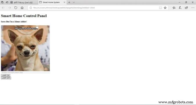
コントロールパネルは非常にシンプルで、サイズの異なる2つのヘッダー、1つの画像、LEDをオンにするためのボタンとオフにするためのボタンが2つ含まれています。
コード
<!DOCTYPE html> スマートホームシステム スマートホームコントロールパネル
申し訳ありませんが私はミーム中毒者です!

コードの説明
- <!DOCTYPE html>: 宣言は、このドキュメントがHMTL5ドキュメントであることを定義しています。
- : HTMLページのルート要素。
- : 要素には、ページに関するメタ情報が含まれています。
- <タイトル>: elementは、ドキュメントのタイトルを指定します。このタイトルは、Webページのブラウザタブに表示されます。
- : 要素には、表示されているWebページのコンテンツが含まれています。
-
:
elementは大きな要素を定義します。 -
:
要素は小さいヘッダーを定義します。ヘッダー値が減少すると、フォントが減少します。 -
: elementは、Webページに画像を追加します。表示する画像は同じプロジェクトフォルダにある必要があります。
-
: カーソルを新しい行に進めます。 - <ボタン>: 要素はページコンテンツにボタンを追加します。
各ボタンは私たちのウェブページであり、 id には非常に重要な2つの属性があります 、および class 属性。 Jqueryコードの説明で、これら2つの値をボタンに割り当てた理由について説明します。
Webページのスタイリング
今後の説明を簡単に理解するために、このクールな記事を読むことをお勧めします CSSイントロ 。
<図>
これで、Webページの見栄えが良くなり(xDが多すぎない)、クールな緑色の背景色を付け、ページコンテンツを中央揃えにし、ヘッダーのフォントの色とフォントファミリを変更して、Webページをより生き生きとさせました。このスタイリングはすべてCSSを使用して行いました。
コード
<!DOCTYPE html> スマートホームシステム スマートホームコントロールパネル
申し訳ありませんが、私はミーム中毒者です!

コードの説明
Webページの見栄えを良くするために、数行のコードを追加しました。 style ="background-color:seagreen; color:seashell; text-align:center;" を追加しました 本体の内部 タグ すべてのWebページのコンテンツをページの中央に配置する 背景色をシーグリーンに設定します フォントの色を貝殻に設定することもできます 。
また、 style ="margin:10px;" を追加しました 2つのボタンタグの内側 各ボタンの4辺の周りに10ピクセルのマージンを設定します。
Webサーバーへのリクエストの送信
今後の説明を簡単に理解するために、このクールな記事を読むことをお勧めします Jqueryのイントロ 。
ここで、Webページの構造を構築してスタイルを設定した後、Webページの前半で追加した2つのボタンにいくつかの機能を追加する必要があります。ユーザーが「LAMPON」ボタンをクリックすると、ブラウザがサーバーに固有のデータを含むリクエストを送信する必要があります(ESP8266-01)。この固有のデータはArduinoにランプをオンにするように指示します。ユーザーがクリックすると2番目のボタン「LAMPOFF」と同じように、ブラウザはサーバーにいくつかの一意のデータを含むリクエストを送信します(ESP8266-01)この一意のデータはArduinoにランプをオフにするように指示します。コードを見てみましょう。
<!DOCTYPE html> スマートホームシステム スマートホームコントロールパネル
申し訳ありませんが、私はミーム中毒者です!
コードの説明
まず最初に、コードにJqueryライブラリをインポートする必要があります。そこで、この行を ヘッドタグに追加しました 。
すべての魔法はこの興味深い部分で起こります。
-
$( "。button")。click(function(){
ユーザーがクラスに関連付けられているボタンをクリックしたとき「ボタン」 、次の関数をトリガーします。
-
var p =$(this).attr( 'id');
クリックされたボタン属性の値を取得する「id」 「p」内に保存します 変数。
-
pin:p
変数「p」値を辞書(key-value)に入れます。キーは「pin」で、値は「p」変数値です。
-
$。get( "http://172.20.10.11:80/"、{pin:p});});
次に、IPアドレスが「172.20.10.11」であるウェブサーバーにGETリクエストを送信します。この GET リクエストには、属性 id の値が含まれています ボタンを押しました。
ユーザーが「LAMPON」ボタンを押した場合、このID値は111になるため、GETリクエストヘッダーにはこの pin =111 のようなデータが含まれます。 。次の図を見てください!
<図>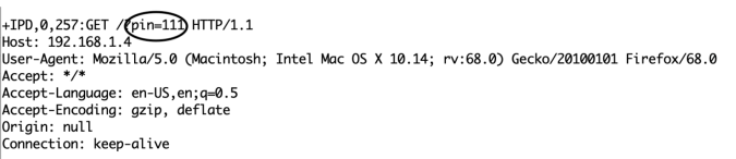
反対側では、ユーザーが「ランプオフ」ボタンを押した場合、リクエストにはこのデータが含まれます pin =110 。
コードロジック
なぜ彼が 111 を選んだのかとあなたが尋ねているのを知っています および 110 具体的には?わかりました、レムはあなたの家族に答えます。実際、その数は 111 および 110 2つの部分に分かれています。
- パート1: は最初の2つの番号で、どちらの場合も「11」になります。これは、制御する必要のある負荷が接続されているArduinoのピン番号を指します。
- パート2: クリックされたボタンに応じて1から0の間で変化する3番目の数字です。そして、それはピンの状態(オンまたはオフ)を指します。
Arduinoコードでは、このデータを受け取り、これら2つの部分を互いに分離し、各部分を異なる変数に保存し、部分1を変数 pinNumber に保存します。 変数 pinState の2番目の部分 、次に、接続された負荷を制御するためのこの単純なコード行を記述します digitalWrite(pinNumber、pinState);
負荷の接続
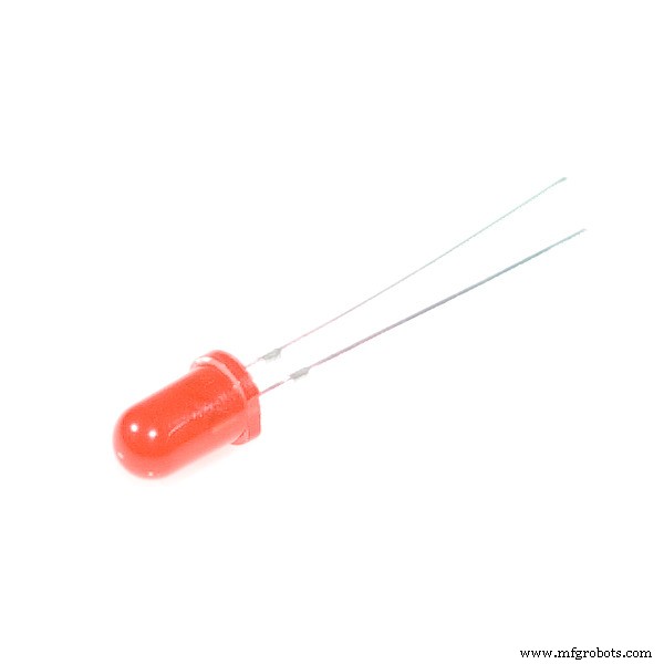
次に、負荷をArduinoボードに接続して制御する必要があります。エアコンやテレビなどの高電圧デバイスを接続する前に、回路とコードをLEDなどの低電圧のものでテストして、すべてが正常に機能していることを確認する必要があります。これが配線図です
<図>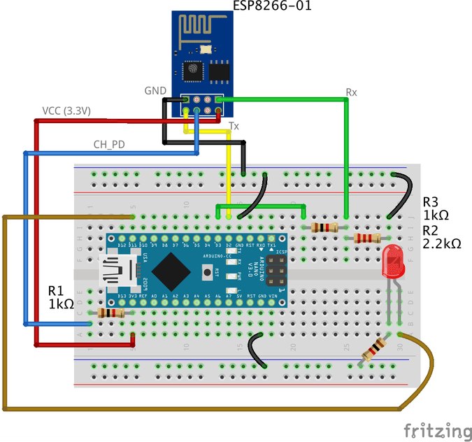
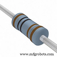
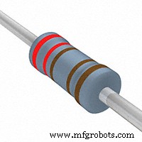
配線は非常に簡単です。LEDの正のレッグをArduinoデジタルピン11に接続し、負のレッグを1kオームの抵抗を介してGNDに接続しています。
Arduinoコード
#include // SoftwareSerialライブラリを含めると、ピン番号を使用できるようになります。 Rx、Txとして2,3。 SoftwareSerial esp8266(2,3); // Rxを設定==>ピン2; TX ==>ピン3。 #define serialCommunicationSpeed 9600 // <=========「serialCommunicationSpeed」という名前の定数を値9600で定義します。これは、ソフトウェアとハードウェアのシリアル通信速度(ボーレート)を参照します。 #define DEBUG true //「DEBUG」という名前の定数を作成します。値はtrueです。後で使用します。 int redLED =12; //整数値12の「redLED」という名前の変数を割り当てます。これは、赤いLEDが接続されているピンを指します。 int blueLED =11; //整数値11の「blueLED」という名前の変数を割り当てます。これは、青色LEDが接続されているピンを参照します。 void setup(){pinMode(redLED、OUTPUT); //ピン番号12を出力ピンとして設定します。 pinMode(blueLED、OUTPUT); //ピン番号11を出力ピンとして設定します。 digitalWrite(redLED、LOW); //プログラムの開始時に赤いLEDをオフにします。 digitalWrite(blueLED、HIGH); //プログラムの開始時に青色のLEDをオンにします。 Serial.begin(serialCommunicationSpeed); //ハードウェアシリアル通信(0、1)を速度9600で開始します。esp8266.begin(serialCommunicationSpeed); //ソフトウェアのシリアル通信(2、3)を速度9600で開始します。InitWifiModule(); //このユーザー定義関数「InitWifiModule()」を呼び出して、ESP8266とアクセスポイント(ホームルーターまたはモバイルホットスポット)間の通信を初期化します。 digitalWrite(blueLED、LOW); //初期化が正常に終了したら、青色のLEDをオフにします(インジケーターのみ)。 } void loop()//メインプログラム、いくつかの楽しみが始まろうとしています){if(esp8266.available())//シリアル受信バッファーで受信および保存されたデータがある場合は、if-condition本体に移動して実行します。そうでない場合は、if-condition本体をまったく実行しないでください。 {if(esp8266.find( "+ IPD、"))//受信データの "+ IPD"文字列を検索します。存在する場合、「。find()」はtrueを返し、存在しない場合はfalseを返します。 {delay(1000); //バッファがデータでいっぱいになるまで1秒待ちます。 int connectionId =esp8266.read()-48; // read()関数はASCII 10進値を返すため、48を減算します。また、0(最初の10進数)は48から始まります。これを使用して、ASCIの10進数値から文字値に変換します。 esp8266.find( "pin ="); //カーソルをリクエストヘッダーの「pin =」部分に移動して、pinNumerとその状態である「pin =」部分の後の着信バイトを読み取ります。 int pinNumber =(esp8266.read()-48)* 10; // Arduino入力バッファから最初のバイトを読み取り(つまり、ピン12の場合、最初の数値は1)、この数値に10を掛けます。したがって、「pinNumber」変数の最終値は10になります。pinNumber=pinNumber + (esp8266.read()-48); // Arduino入力バッファから2番目のバイトを読み取り(つまり、ピン番号が12の場合、2番目の番号は2)、この番号を最初の番号に追加します。したがって、「pinNumber」変数の最終値は12になります。intstatusLed=(esp8266.read()-48); // Arduino入力バッファから3番目のバイトを読み取ります。次に、それを「statusLed」変数内に保存します。いずれの場合も、1または0になります。digitalWrite(pinNumber、statusLed); //次に、「statusLed」変数の値に応じて、「pinNumber」のLEDをオンまたはオフにします。 Serial.println(connectionId); //デバッグ目的でシリアルモニターに「connectionId」値を出力します。 Serial.print(pinNumber); //デバッグ目的でシリアルモニターに「pinNumber」値を出力します。 Serial.print( ""); //読みやすくするために、シリアルモニターにいくつかのスペースを印刷します。 Serial.println(statusLed); //デバッグ目的でシリアルモニターに「statusLed」値を出力します。 String closeCommand ="AT + CIPCLOSE ="; // TCP / IP接続を閉じます。 closeCommand + =connectionId; //「connectionId」値を文字列に追加します。 closeCommand + ="\ r \ n"; //文字列に「\ r \ n」を追加します。キーボードのエンターキーをシミュレートします。 sendData(closeCommand、1000、DEBUG); //次に、このコマンドをESP8266モジュールに送信して実行します。 }}} / ********************************************** ************************************************** ************************************************** **************************************** *名前:sendData *説明:この関数は調整しますATコマンドがESP8266に送信される方法。 * * Params:command - the AT Command to send * - timeout - the time to wait for a response * - debug - print to Serial window?(true =yes, false =no) * * Returns:The response from the esp8266 (if there is a reponse) */ String sendData(String command, const int timeout, boolean debug) { String response =""; //initialize a String variable named "response". we will use it later. esp8266.print(command); //send the AT command to the esp8266 (from ARDUINO to ESP8266). long int time =millis(); //get the operating time at this specific moment and save it inside the "time" variable. while( (time+timeout)> millis()) //excute only whitin 1 second. { while(esp8266.available()) //is there any response came from the ESP8266 and saved in the Arduino input buffer? { char c =esp8266.read(); //if yes, read the next character from the input buffer and save it in the "response" String variable. response+=c; //append the next character to the response variabl. at the end we will get a string(array of characters) contains the response. } } if(debug) //if the "debug" variable value is TRUE, print the response on the Serial monitor. { Serial.print(response); } return response; //return the String response. } /****************************************************************************************************************************************************************************************** * Name:InitWifiModule * Description:this Function gives the commands that we need to send to the sendData() function to send it. * * Params:Nothing. * * Returns:Nothing (void). */ void InitWifiModule() { sendData("AT+RST\r\n", 2000, DEBUG); //reset the ESP8266 module. //delay(1000); sendData("AT+CWJAP=\"PUT YOUR SSID\",\"PUT YOUR PASSWORD\"\r\n", 2000, DEBUG); //connect to the WiFi network. delay (3000); sendData("AT+CWMODE=1\r\n", 1500, DEBUG); //set the ESP8266 WiFi mode to station mode.遅延(1000); sendData("AT+CIFSR\r\n", 1500, DEBUG); //Show IP Address, and the MAC Address.遅延(1000); sendData("AT+CIPMUX=1\r\n", 1500, DEBUG); //Multiple conections.遅延(1000); sendData("AT+CIPSERVER=1,80\r\n", 1500, DEBUG); //start the communication at port 80, port 80 used to communicate with the web servers through the http requests. } code explanation
the code is pretty straightforward, we implemented two different functions InitWifiModule() and sendData()
The sendData() function job is regulating how the AT commands will get sent to the ESP8266-01 module.
the InitWifiModule() function job is to provide the sendData() function the AT commands that we need to send to the ESP8266-01.
in the loop() function we read the income HTTP request header and search for the “+IPD, ” which means that the request has successfully arrived, then we read the pin value which it will be “111” if the user clicked the “LAMP ON” button and “110” if the user clicked “LAMP OFF” button.
Don’t forget to put your wifi SSID and Password in the Arduino code line no. 103 sendData("AT+CWJAP=\"PUT YOUR SSID\",\"PUT YOUR PASSWORD\"\r\n", 2000, DEBUG);
For more code explanation please read the comments in the code, it’s well documented
仕組み
After uploading the code to the Arduino board, open the Serial monitor and read the responses that the ESP module is sending.
<図>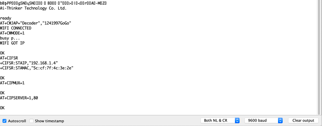
at the beginning of the program, if you see something like the previous figure with “OK” at the end of the page, it means that the ESP8266-01 module is successfully connected to your wifi (Access point) and got an IP and MAC address. Now, you can open your fancy web page and try to control some stuff 😉
<図>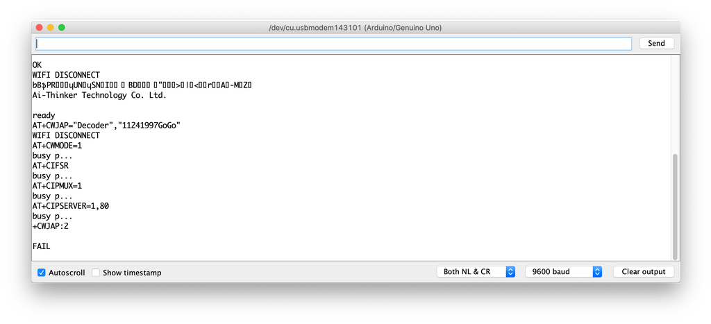
But, if you see something like the previous figure with a “FAIL” or “ERROR” at the end of the page, it means that your ESP module cant connect to your wifi (Access point) for some reasons, try to check if entered the right SSID and password for your network.
Adding a High Voltage Load
After we tested our code and got sure that everything is working like a charm, we need to replace this boring LED with a High voltage load like an air conditioner, TV or a light bulb. But to control all of these high voltage appliances we have to deal with relays 。
<図>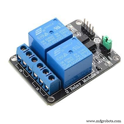
What’s and why relays? Ok, the relay is a mechanical switch, which is toggled on or off by energizing a coil. it’s mainly used to control a high powered circuit using a low power signal (5V or 0V). So we can control a high powered device like an air conditioner or an AC lamp turning it on or off only by a 5V or 0V signal. Which is amazing!
<図>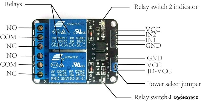
The Two-channel relay module has two control pins(IN1, IN2) these pins should get connected to two Arduino digital pins to control the state of the two coils, closes or opens the load circuit.
<図>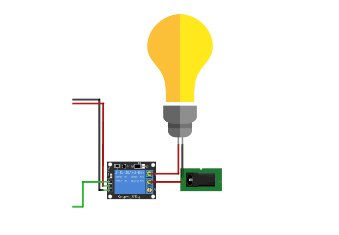
At the opposite side of the relay module, the COM(common) should get connected to one end of the load. the other end of the load is either connected to the NC(Normally Close) or NO(Normally open) , if connected to the NO the load remains Disconnected before trigger and vice versa.
Wiring Diagram
<図>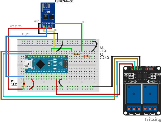
As you see, we are using a two-channel relay module that gives us the ability to control two different AC loads. We are connecting the first relay at digital output pin11(Arduino) and the second relay to digital output pin 12(Arduino)
We will make a small modification to our web page, we will add another two buttons(ON and OFF) to control the second connected load.
Smart Home System Smart Home Control Panel
Sorry But I'm a Meme Addict!

How It Works
Just like the last trial, You upload the Arduino code to the board (if not uploaded yet) and open the serial monitor and make sure that your ESP module is connected successfully to your access point and got an IP and MAC address.
Then open your fancy web page and start controlling your stuff 😉
Make it more professional!
What about transferring our breadboard circuit to a professional printed circuit board (PCB) to make our project more rigid and solid, I designed the project circuit using Autodesk Eagle software. all the PCB files are open-source you can access it from this link:https://www.pcbway.com/project/shareproject/IoT_Using_Arduino_and_ESP8266_01.html
Because we love open source 😉
<図>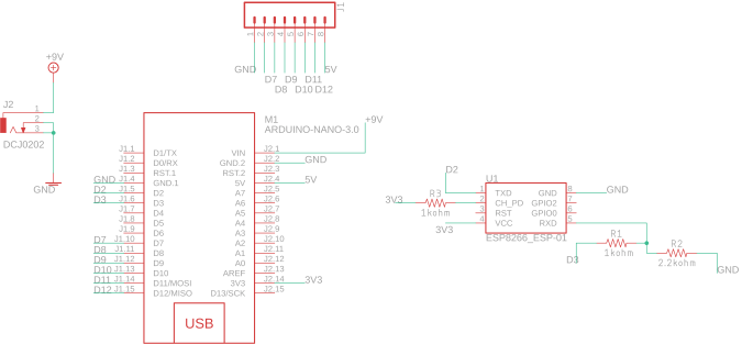 <図>
<図> 
You can order your own PCB From PCBWay company these guys have a very good reputation in this field and they ship to more than 170 countries around the world with reasonable prices. all you have to do is to open the project PCB files link and press “Add to cart”. That’s it!
<図>
Troubleshooting
if your ESP Module is successfully connected to your access point but there is no action happens when you click the web page buttons
- make sure that you are sending the request from your web browser from port 80(HTTP). example:
$.get("http://192.168.1.4:80/"
- make sure that your PC or Laptop and the ESP module is connected to the same Access point.
- In Jquery code, make sure that you wrote the right ESP module IP address.
- Make sure that you are connecting the load at Arduino digital pins 11 and 12.
- Don’t forget to save the Web page code file after any change or modification, and reload the web page in the web browser after any code modification to take effect.
Final
We are done! in today’s tutorial, we learned how to build a simple web page using HTML, CSS, and jquery. Also, we learned how to control an AC load wirelessly from a web-based control panel, and how to use the awesome ESP8266-01 Wifi module with the Arduino board.
you wanna see more Tutorials and open source projects you can also visit my blog www.makesomestuff.org
Lastly, if you have any questions drop it in the comments section below, I will be more than happy to hear from you 😉
コード
- Web Page
- Final Arduino Code
Web PageHTML
Smart Home System Smart Home Control Panel
Sorry But I'm a Meme Addict!
Final Arduino CodeArduino
#include//including the SoftwareSerial library will allow you to use the pin no. 2,3 as Rx, Tx.SoftwareSerial esp8266(2,3); //set the Rx ==> Pin 2; TX ==> Pin3.#define serialCommunicationSpeed 9600 // <=========define a constant named "serialCommunicationSpeed" with a value 9600. it referes to the Software and hardware serial communication speed(baud rate).#define DEBUG true //make a constant named "DEBUG" and it's value true. we will use it later.int redLED =12; //assign a variable named "redLED" with an integer value 12, it refers to the pin which the red LED is connected on.int blueLED =11; //assign a variable named "blueLED" with an integer value 11, it refers to the pin which the blue LED is connected on.void setup(){ pinMode(redLED,OUTPUT); //set the pin number 12 as an output pin. pinMode(blueLED、OUTPUT); //set the pin number 11 as an output pin. digitalWrite(redLED,LOW); //turn the red LED off at the beginning of the program. digitalWrite(blueLED、HIGH); //turn the blue LED on at the beginning of the program. Serial.begin(serialCommunicationSpeed); //begin the Hardware serial communication (0, 1) at speed 9600. esp8266.begin(serialCommunicationSpeed); //begin the software serial communication (2, 3) at speed 9600. InitWifiModule(); //call this user-defined function "InitWifiModule()" to initialize a communication between the ESP8266 and your access point (Home Router or even your mobile hotspot). digitalWrite(blueLED、LOW); //after finishing the initialization successfully, turn off the blue LED (just an indicator).}void loop() //our main program, some fun are about to start){ if(esp8266.available()) //if there's any data received and stored in the serial receive buffer, go and excute the if-condition body. If not, dont excute the if-condition body at all. { if(esp8266.find("+IPD,")) //search for the "+IPD," string in the incoming data. if it exists the ".find()" returns true and if not it returns false. { delay(1000); //wait 1 second to fill up the buffer with the data. int connectionId =esp8266.read()-48; //Subtract 48 because the read() function returns the ASCII decimal value. And 0 (the first decimal number) starts at 48. We use it to convert from ASCI decimal value to a character value. esp8266.find("pin="); //Advance the cursor to the "pin=" part in the request header to read the incoming bytes after the "pin=" part which is the pinNumer and it's state. int pinNumber =(esp8266.read()-48)*10; //read the first Byte from the Arduino input buffer(i.e. if the pin 12 then the 1st number is 1) then multiply this number by 10. So, the final value of the "pinNumber" variable will be 10. pinNumber =pinNumber + (esp8266.read()-48); //read the second Byte from the Arduino input buffer(i.e. if the pin number is 12 then the 2nd number is 2) then add this number to the first number. So, the final value of the "pinNumber" variable will be 12. int statusLed =(esp8266.read()-48); //read the third byte from the Arduino input buffer. then save it inside the "statusLed" variable. At any case, it will be 1 or 0. digitalWrite(pinNumber, statusLed); //then turn the LED at "pinNumber" on or off depending on the "statusLed" variable value. Serial.println(connectionId); //print the "connectionId" value on the serial monitor for debugging purposes. Serial.print(pinNumber); //print the "pinNumber" value on the serial monitor for debugging purposes. Serial.print( ""); //print some spaces on the serial monitor to make it more readable. Serial.println(statusLed); //print the "statusLed" value on the serial monitor for debugging purposes. String closeCommand ="AT+CIPCLOSE="; //close the TCP/IP connection. closeCommand+=connectionId; //append the "connectionId" value to the string. closeCommand+="\r\n"; //append the "\r\n" to the string. it simulates the keyboard enter press. sendData(closeCommand,1000,DEBUG); //then send this command to the ESP8266 module to excute it. } }}/******************************************************************************************************************************************************************************************* Name:sendData* Description:this Function regulates how the AT Commands will ge sent to the ESP8266.* * Params:command - the AT Command to send * - timeout - the time to wait for a response * - debug - print to Serial window?(true =yes, false =no)* * Returns:The response from the esp8266 (if there is a reponse)*/String sendData(String command, const int timeout, boolean debug){ String response =""; //initialize a String variable named "response". we will use it later. esp8266.print(command); //send the AT command to the esp8266 (from ARDUINO to ESP8266). long int time =millis(); //get the operating time at this specific moment and save it inside the "time" variable. while( (time+timeout)> millis()) //excute only whitin 1 second. { while(esp8266.available()) //is there any response came from the ESP8266 and saved in the Arduino input buffer? { char c =esp8266.read(); //if yes, read the next character from the input buffer and save it in the "response" String variable. response+=c; //append the next character to the response variabl. at the end we will get a string(array of characters) contains the response. } } if(debug) //if the "debug" variable value is TRUE, print the response on the Serial monitor. { Serial.print(response); } return response; //return the String response.}/******************************************************************************************************************************************************************************************* Name:InitWifiModule* Description:this Function gives the commands that we need to send to the sendData() function to send it.* * Params:Nothing.* * Returns:Nothing (void).*/void InitWifiModule(){ sendData("AT+RST\r\n", 2000, DEBUG); //reset the ESP8266 module. //delay(1000); sendData("AT+CWJAP=\"Decoder\",\"1241997GoGo\"\r\n", 2000, DEBUG); //connect to the WiFi network. delay (3000); sendData("AT+CWMODE=1\r\n", 1500, DEBUG); //set the ESP8266 WiFi mode to station mode. delay (1500); sendData("AT+CIFSR\r\n", 1500, DEBUG); //Show IP Address, and the MAC Address. delay (1500); sendData("AT+CIPMUX=1\r\n", 1500, DEBUG); //Multiple conections. delay (1500); sendData("AT+CIPSERVER=1,80\r\n", 1500, DEBUG); //start the communication at port 80, port 80 used to communicate with the web servers through the http requests.}
回路図
製造プロセス
- TinyML-言語検出器-エッジインパルスとArduinoに基づく
- MPU-6050を搭載したArduinoジャイロスコープゲーム
- Arduino Digital Dice
- ARDUINOを使用した超音波浮揚機
- Arduinoとスマートフォンを使用したDIY電圧計
- IoTを使用した心拍数モニター
- IOT-ESP8266、Arduino、超音波センサーを使用したスマートジャー
- arduinoを使用したソナーと処理IDEでの表示
- BoltとArduinoを使用したLEDの明るさの制御
- AlexaとArduinoIoTCloudを使用したテレビのフルコントロール
- ArduinoとRDA8057Mを使用したFMラジオ