


ArduinoとADXL345加速度計で向きを追跡する方法
このチュートリアルでは、ArduinoとADXL345加速度センサーを使用して角度とトラックの向きを測定する方法を学習します。詳細については、次のビデオを見るか、以下のチュートリアルを読むことができます。
まず、センサーの仕組みとセンサーからのデータの読み取り方法について説明し、次に、Processing開発環境を使用して、加速度計の向きを3Dで視覚化します。
まず、ADXL345センサーがどのように機能するかを見てみましょう。これは、静的および動的な加速度の両方の力を測定できる3軸加速度計です。地球の重力は静的な力の典型的な例ですが、動的な力は振動や動きなどによって引き起こされる可能性があります。
加速度の測定単位はメートル/秒の2乗(m / s ^ 2)です。ただし、加速度センサーは通常、測定値を「g」または重力で表します。 1つの「g」は地球の重力の値であり、毎秒9.8メートルの2乗に相当します。
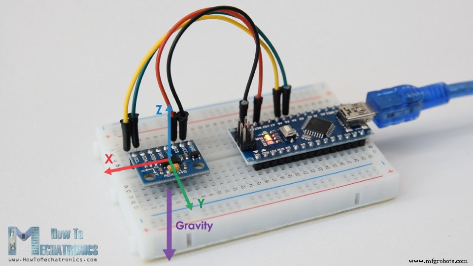
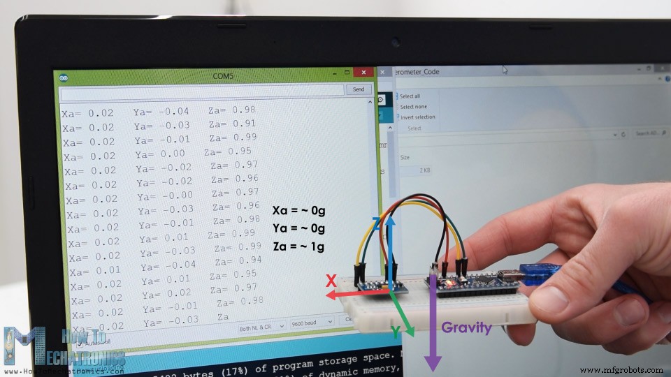
したがって、重力とは反対に、Z軸が上を向くように加速度計を平らに配置すると、センサーのZ軸出力は1gになります。一方、重力はこれらの軸に垂直であり、軸にまったく影響を与えないため、X出力とY出力はゼロになります。
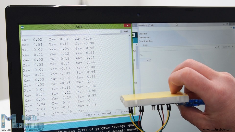
センサーを上下逆にすると、Z軸出力は-1gになります。これは、重力に対するセンサーの向きによるセンサーの出力が-1gから+1gまで変化する可能性があることを意味します。
したがって、このデータと三角法の計算に基づいて、センサーが配置されている角度を計算できます。
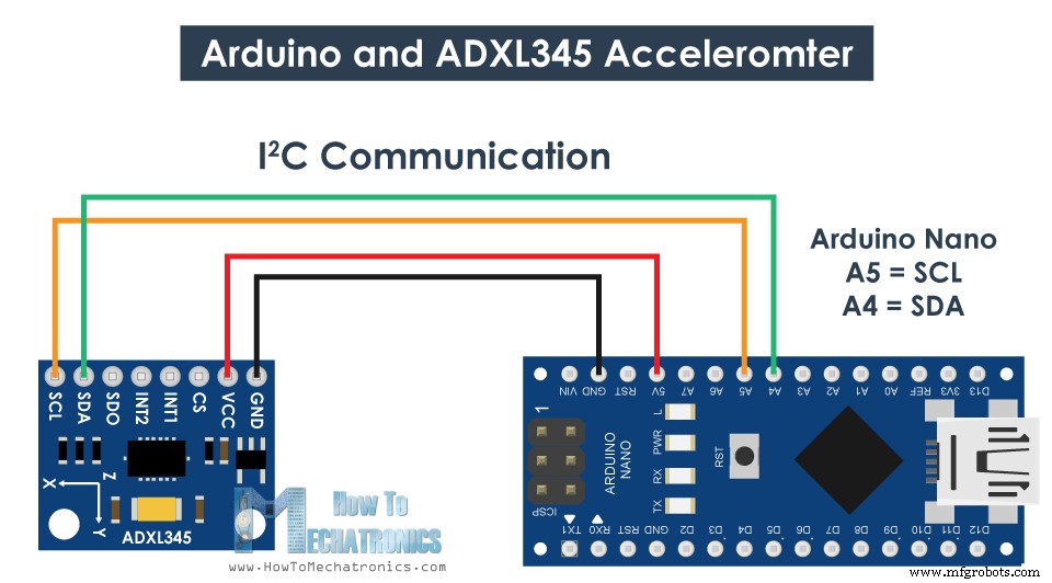
では、Arduinoを使用してADXL345加速度計データを読み取る方法を見てみましょう。このセンサーは、Arduinoとの通信にI2Cプロトコルを使用しているため、センサーを接続するために2本のワイヤーと、電源を供給するために2本のワイヤーが必要です。
このArduinoチュートリアルに必要なコンポーネントは、以下のリンクから入手できます。
ADXL345加速度計データを読み取るためのArduinoコードは次のとおりです。
説明: したがって、最初に、I2C通信に使用されるWire.hライブラリを含める必要があります。 I2C通信の仕組みと、Arduinoでの使用方法について詳しく知りたい場合は、他の詳細なチュートリアルを確認してください。
I2C通信を使用する各デバイスには一意のI2Cアドレスがあり、このアドレスはセンサーのデータシート(ADXL345データセット)に記載されています。したがって、3つの出力のアドレスと変数を定義したら、セットアップセクションで、最初にワイヤライブラリを初期化し、次に加速度計を測定モードに設定する必要があります。そのためには、データシートをもう一度見てみると、POWER_CTLレジスタのビットD3をHIGHに設定する必要があることがわかります。
したがって、beginTransmission()関数を使用して通信を開始し、次にwrite()関数を使用してアクセスするレジスタを指定し、write()関数を使用してD3ビットをHIGHに設定します。ビットD3をHIGHに設定することに対応する10進数。
ループセクションでは、センサーからデータを読み取ります。各軸のデータは、2バイトまたはレジスタに格納されます。これらのレジスタのアドレスは、データシートから確認できます。
それらすべてを読み取るために、最初のレジスターから開始し、requestionFrom()関数を使用して6つのレジスターを読み取るように要求します。次に、read()関数を使用して、各レジスタからデータを読み取ります。出力は2の補数であるため、適切に組み合わせて正しい値を取得します。
センサーからの出力値は、実際には選択した感度に依存し、+-2gから+-16gまで変化する可能性があります。デフォルトの感度は+-2gであるため、-1から+ 1gの値を取得するには、出力を256で割る必要があります。 256 LSB / gは、gあたり256カウントがあることを意味します。
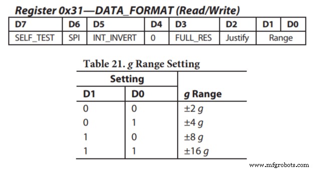
アプリケーションに応じて、適切な感度を選択できます。この場合、方向を追跡するために+ -2gの感度で問題ありませんが、突然の動きや衝撃などからより高い加速力を感知する必要があるアプリケーションでは、DATA_FORMATレジスタとを使用して他の感度範囲のいくつかを選択できます。そのD1ビットとD0ビット。
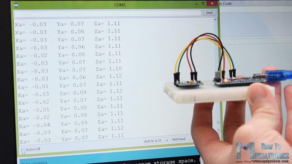
それでも、データを読み取ったら、シリアルモニターに印刷するだけで、値が期待どおりかどうかを確認できます。私の場合、得られた値は正確に正しい値ではありませんでした。特に、0.1gの顕著な誤差があったZ軸はそうでした。
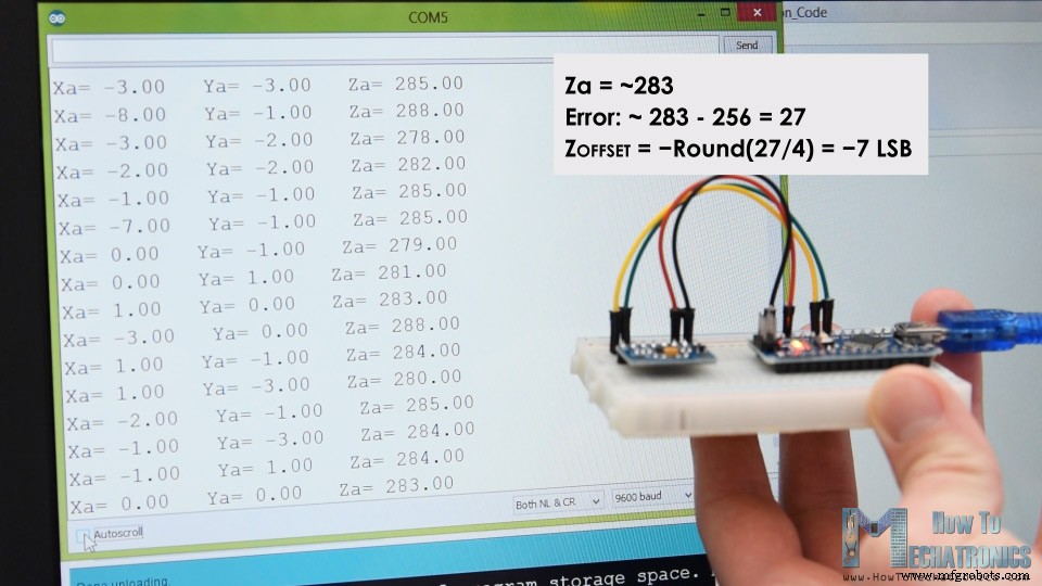
この問題を解決するには、3つのオフセットキャリブレーションレジスタを使用して加速度計をキャリブレーションする必要があります。これを行う方法は次のとおりです。したがって、センサーを平らに配置し、RAW値を256で割らずに印刷する必要があります。
ここから、出力がどれだけオフになっているかがわかります。私の場合、Z出力は約283でした。これは、正の値で27の差です。ここで、この値を4で割る必要があります。これにより、Z軸オフセットレジスタに書き込む必要のある数値が使用されます。ここでコードをアップロードすると、Z軸の出力は正確に256、つまり1gになります。
必要に応じて、同じ方法を使用して他の軸を調整する必要があります。また、このキャリブレーションはレジスタに永続的に書き込まれるわけではないことに注意してください。センサーの電源を入れるたびに、これらの値をレジスタに書き込む必要があります。
キャリブレーションが完了したら、これら2つの式を使用して、ロールとピッチ、またはX軸を中心とした回転とY軸を中心とした回転を最終的に計算できます。
これらの式がどのように機能するかについての詳細は、このFreescaleSemiconductorアプリケーションノートを確認してください。
では、加速度計の3D視覚化の例を見てみましょう。
したがって、同じコードを使用して、シリアルポートを介してロール値とピッチ値を送信します。完全なArduinoコードは次のとおりです:
処理開発環境では、これらの値を受け取り、それらを使用して、作成する3Dオブジェクトを回転させる必要があります。完全な処理コードは次のとおりです。
説明: したがって、ここでは、シリアルライブラリを含め、シリアルポートと、アップロードされたArduinoスケッチのボーレートと一致する必要があるボーレートを定義する必要があります。次に、受信データを読み取り、適切なロール変数とピッチ変数に入れます。メインの描画ループでは、これらの値を使用して3Dオブジェクトを回転させます。この場合、これは特定の色とテキストが含まれる単純なボックスです。
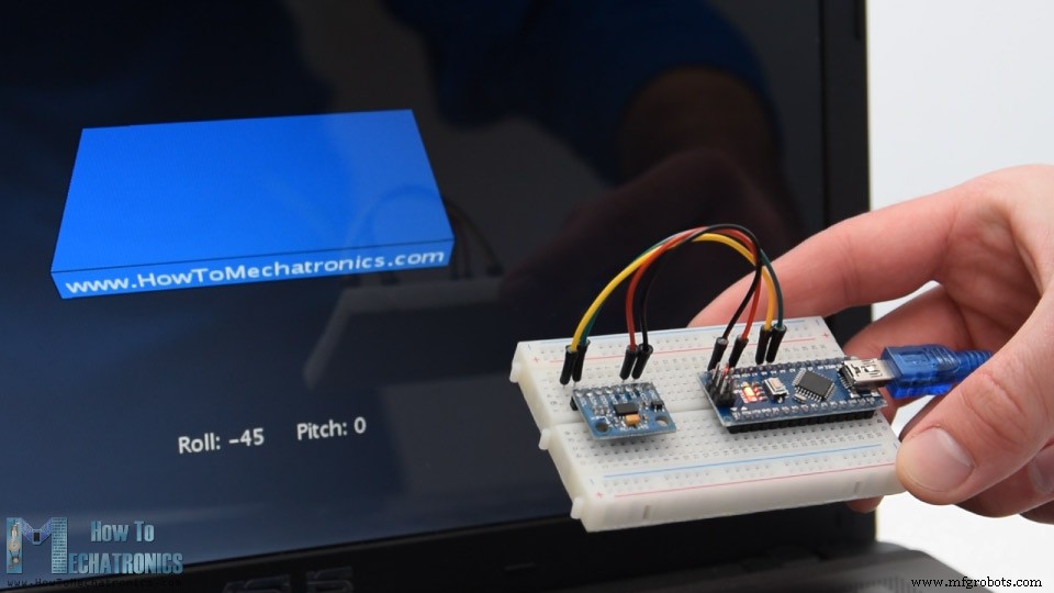
スケッチを実行すると、3Dオブジェクトが表示され、加速度センサーの方向が追跡されます。ここで、オブジェクトが実際には少し揺れていることがわかります。これは、加速度計が重力だけでなく、手の動きによって生成される小さな力もキャプチャするためです。よりスムーズな結果を得るために、単純なローパスフィルターを使用できます。ここでは、このようなフィルターをArduinoコードに実装しました。これは、以前の状態の94%を取り、現在の状態または角度の6%を追加します。
このフィルターを使用すると、オブジェクトの移動が非常にスムーズになりますが、副作用もあり、応答が遅くなります。また、ヨー、つまりZ軸を中心とした回転が欠落していることもわかります。 3軸加速度計のデータのみを使用して、ヨーを計算することはできません。
これを行い、方向追跡センサーの全体的なパフォーマンスを向上させるには、実際には追加のセンサー、ジャイロスコープを含め、そのデータを加速度計と融合させる必要があります。
したがって、ADXL345加速度計をジャイロスコープセンサーと組み合わせて使用することも、3軸加速度計と3軸ジャイロスコープの両方を1つのチップに統合したMPU6050IMUを使用することもできます。このセンサーの詳細なチュートリアルは、次のビデオで見つけることができます。
このチュートリアルを楽しんで、何か新しいことを学んだことを願っています。以下のコメントセクションでお気軽に質問してください。Arduinoプロジェクトのコレクションを確認することを忘れないでください。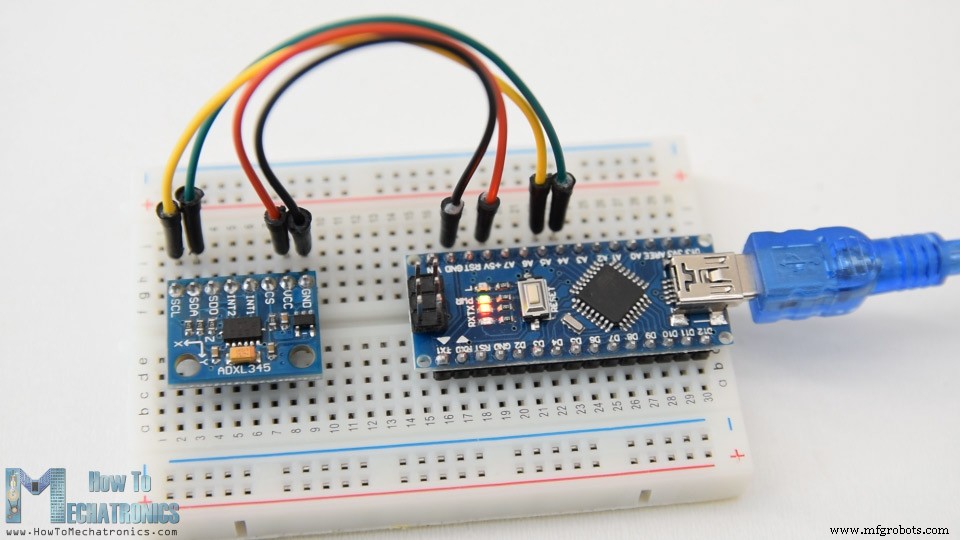
ADXL345加速度計のしくみ
ArduinoでADXL345加速度計データを読み取る方法
ADXL345加速度計Arduinoコード
/*
    Arduino and ADXL345 Accelerometer Tutorial
     by Dejan, https://howtomechatronics.com
*/

#include <Wire.h>  // Wire library - used for I2C communication

int ADXL345 = 0x53; // The ADXL345 sensor I2C address

float X_out, Y_out, Z_out;  // Outputs

void setup() {
  Serial.begin(9600); // Initiate serial communication for printing the results on the Serial monitor
  Wire.begin(); // Initiate the Wire library
  // Set ADXL345 in measuring mode
  Wire.beginTransmission(ADXL345); // Start communicating with the device
  Wire.write(0x2D); // Access/ talk to POWER_CTL Register - 0x2D
  // Enable measurement
  Wire.write(8); // (8dec -> 0000 1000 binary) Bit D3 High for measuring enable
  Wire.endTransmission();
  delay(10);
}

void loop() {
  // === Read acceleromter data === //
  Wire.beginTransmission(ADXL345);
  Wire.write(0x32); // Start with register 0x32 (ACCEL_XOUT_H)
  Wire.endTransmission(false);
  Wire.requestFrom(ADXL345, 6, true); // Read 6 registers total, each axis value is stored in 2 registers
  X_out = ( Wire.read()| Wire.read() << 8); // X-axis value
  X_out = X_out/256; //For a range of +-2g, we need to divide the raw values by 256, according to the datasheet
  Y_out = ( Wire.read()| Wire.read() << 8); // Y-axis value
  Y_out = Y_out/256;
  Z_out = ( Wire.read()| Wire.read() << 8); // Z-axis value
  Z_out = Z_out/256;

  Serial.print("Xa= ");
  Serial.print(X_out);
  Serial.print("   Ya= ");
  Serial.print(Y_out);
  Serial.print("   Za= ");
  Serial.println(Z_out);
}Code language: Arduino (arduino)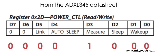
// Set ADXL345 in measuring mode
  Wire.beginTransmission(ADXL345); // Start communicating with the device
  Wire.write(0x2D); // Access/ talk to POWER_CTL Register - 0x2D
  // Enable measurement
  Wire.write(8); // (8dec -> 0000 1000 binary) Bit D3 High for measuring enable
  Wire.endTransmission();Code language: Arduino (arduino)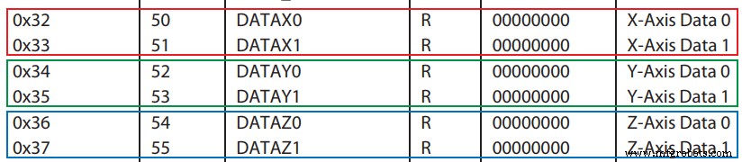
// === Read acceleromter data === //
  Wire.beginTransmission(ADXL345);
  Wire.write(0x32); // Start with register 0x32 (ACCEL_XOUT_H)
  Wire.endTransmission(false);
  Wire.requestFrom(ADXL345, 6, true); // Read 6 registers total, each axis value is stored in 2 registers
  X_out = ( Wire.read()| Wire.read() << 8); // X-axis value
  X_out = X_out/256; //For a range of +-2g, we need to divide the raw values by 256, according to the datasheet
  Y_out = ( Wire.read()| Wire.read() << 8); // Y-axis value
  Y_out = Y_out/256;
  Z_out = ( Wire.read()| Wire.read() << 8); // Z-axis value
  Z_out = Z_out/256;Code language: Arduino (arduino)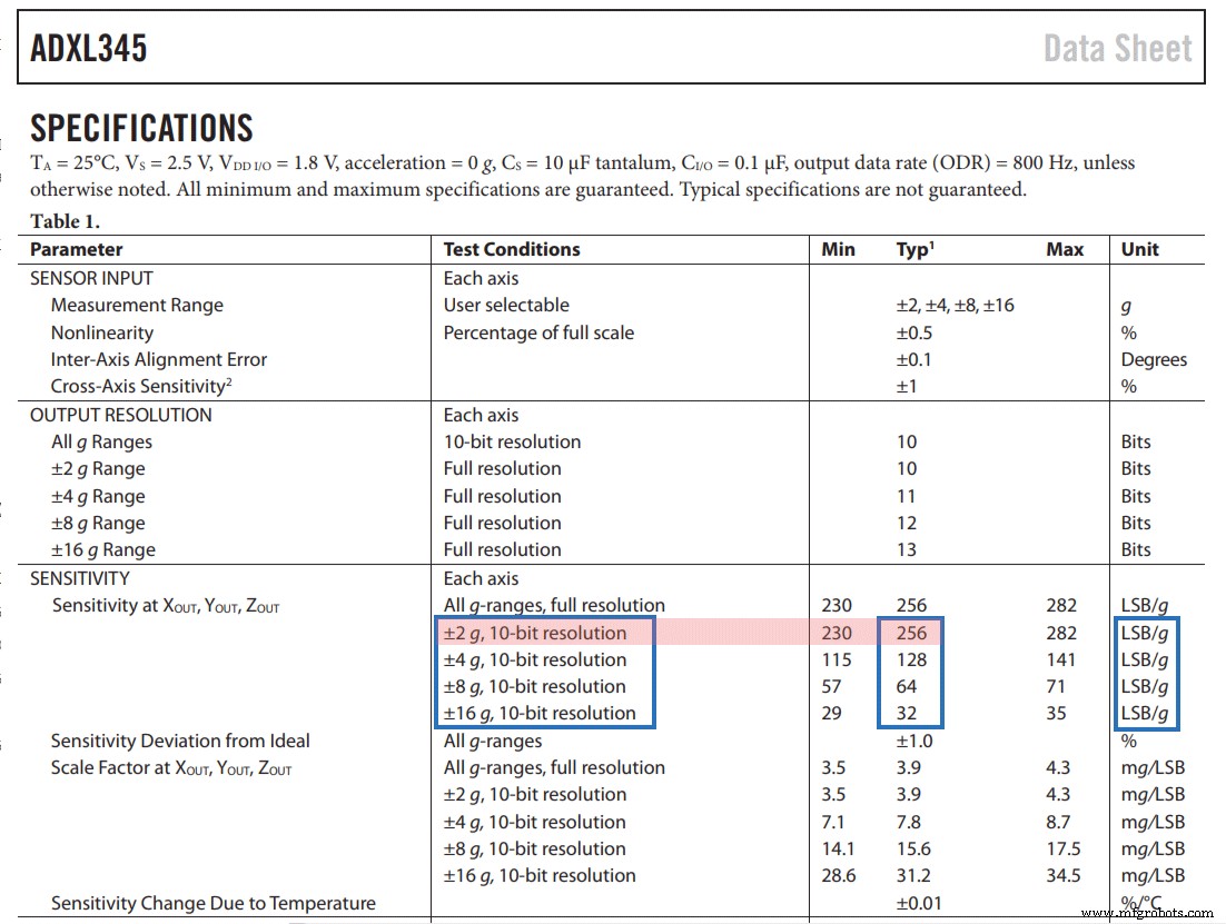
ADXL345加速度計のキャリブレーション
// This code goes in the SETUP section
// Off-set Calibration
  //X-axis
  Wire.beginTransmission(ADXL345);
  Wire.write(0x1E);  // X-axis offset register
  Wire.write(1);
  Wire.endTransmission();
  delay(10);
  //Y-axis
  Wire.beginTransmission(ADXL345);
  Wire.write(0x1F); // Y-axis offset register
  Wire.write(-2);
  Wire.endTransmission();
  delay(10);

  //Z-axis
  Wire.beginTransmission(ADXL345);
  Wire.write(0x20); // Z-axis offset register
  Wire.write(-7);
  Wire.endTransmission();
delay(10);Code language: Arduino (arduino)// Calculate Roll and Pitch (rotation around X-axis, rotation around Y-axis)
roll = atan(Y_out / sqrt(pow(X_out, 2) + pow(Z_out, 2))) * 180 / PI;
pitch = atan(-1 * X_out / sqrt(pow(Y_out, 2) + pow(Z_out, 2))) * 180 / PI;Code language: Arduino (arduino) ArduinoおよびADXL345加速度計の向きの追跡–3D視覚化
/*
    Arduino and ADXL345 Accelerometer - 3D Visualization Example
     by Dejan, https://howtomechatronics.com
*/
#include <Wire.h>  // Wire library - used for I2C communication

int ADXL345 = 0x53; // The ADXL345 sensor I2C address

float X_out, Y_out, Z_out;  // Outputs
float roll,pitch,rollF,pitchF=0;

void setup() {
  Serial.begin(9600); // Initiate serial communication for printing the results on the Serial monitor

  Wire.begin(); // Initiate the Wire library
  // Set ADXL345 in measuring mode
  Wire.beginTransmission(ADXL345); // Start communicating with the device
  Wire.write(0x2D); // Access/ talk to POWER_CTL Register - 0x2D
  // Enable measurement
  Wire.write(8); // Bit D3 High for measuring enable (8dec -> 0000 1000 binary)
  Wire.endTransmission();
  delay(10);

  //Off-set Calibration
  //X-axis
  Wire.beginTransmission(ADXL345);
  Wire.write(0x1E);
  Wire.write(1);
  Wire.endTransmission();
  delay(10);
  //Y-axis
  Wire.beginTransmission(ADXL345);
  Wire.write(0x1F);
  Wire.write(-2);
  Wire.endTransmission();
  delay(10);

  //Z-axis
  Wire.beginTransmission(ADXL345);
  Wire.write(0x20);
  Wire.write(-9);
  Wire.endTransmission();
  delay(10);
}

void loop() {
  // === Read acceleromter data === //
  Wire.beginTransmission(ADXL345);
  Wire.write(0x32); // Start with register 0x32 (ACCEL_XOUT_H)
  Wire.endTransmission(false);
  Wire.requestFrom(ADXL345, 6, true); // Read 6 registers total, each axis value is stored in 2 registers
  X_out = ( Wire.read() | Wire.read() << 8); // X-axis value
  X_out = X_out / 256; //For a range of +-2g, we need to divide the raw values by 256, according to the datasheet
  Y_out = ( Wire.read() | Wire.read() << 8); // Y-axis value
  Y_out = Y_out / 256;
  Z_out = ( Wire.read() | Wire.read() << 8); // Z-axis value
  Z_out = Z_out / 256;

  // Calculate Roll and Pitch (rotation around X-axis, rotation around Y-axis)
  roll = atan(Y_out / sqrt(pow(X_out, 2) + pow(Z_out, 2))) * 180 / PI;
  pitch = atan(-1 * X_out / sqrt(pow(Y_out, 2) + pow(Z_out, 2))) * 180 / PI;

  // Low-pass filter
  rollF = 0.94 * rollF + 0.06 * roll;
  pitchF = 0.94 * pitchF + 0.06 * pitch;

  Serial.print(rollF);
  Serial.print("/");
  Serial.println(pitchF);
}Code language: Arduino (arduino)/*
Arduino and ADXL345 Accelerometer - 3D Visualization Example
by Dejan, https://howtomechatronics.com
*/
import processing.serial.*;
import java.awt.event.KeyEvent;
import java.io.IOException;
Serial myPort;
String data="";
float roll, pitch;
void setup() {
size (960, 640, P3D);
myPort = new Serial(this, "COM8", 9600); // starts the serial communication
myPort.bufferUntil('\n');
}
void draw() {
translate(width/2, height/2, 0);
background(33);
textSize(22);
text("Roll: " + int(roll) + " Pitch: " + int(pitch), -100, 265);
// Rotate the object
rotateX(radians(roll));
rotateZ(radians(-pitch));
// 3D 0bject
textSize(30);
fill(0, 76, 153);
box (386, 40, 200); // Draw box
textSize(25);
fill(255, 255, 255);
text("www.HowToMechatronics.com", -183, 10, 101);
//delay(10);
//println("ypr:\t" + angleX + "\t" + angleY); // Print the values to check whether we are getting proper values
}
// Read data from the Serial Port
void serialEvent (Serial myPort) {
// reads the data from the Serial Port up to the character '.' and puts it into the String variable "data".
data = myPort.readStringUntil('\n');
// if you got any bytes other than the linefeed:
if (data != null) {
data = trim(data);
// split the string at "/"
String items[] = split(data, '/');
if (items.length > 1) {
//--- Roll,Pitch in degrees
roll = float(items[0]);
pitch = float(items[1]);
}
}
}Code language: Arduino (arduino)// Low-pass filter
rollF = 0.94 * rollF + 0.06 * roll;
pitchF = 0.94 * pitchF + 0.06 * pitch;Code language: Arduino (arduino)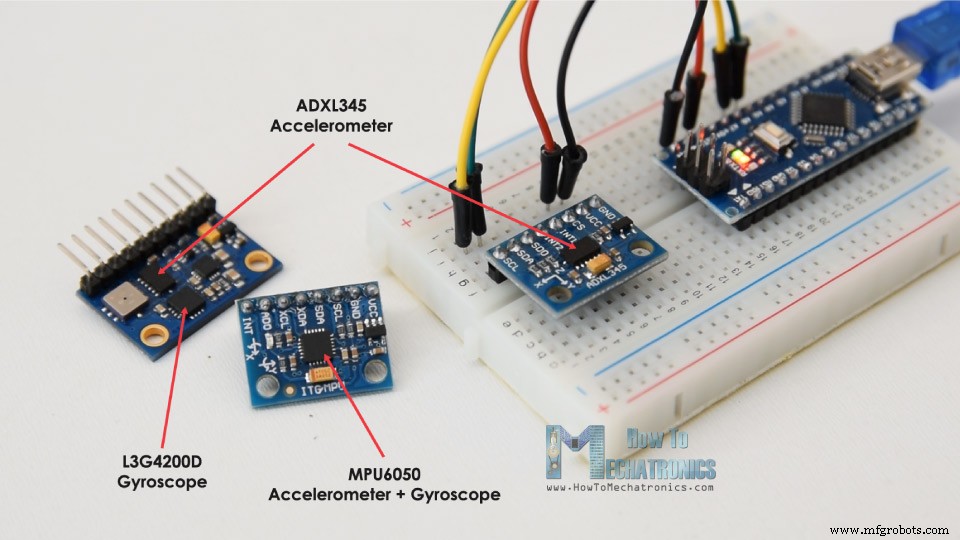
製造プロセス
- ArduinoとMPU6050によるサーボモーターの制御
- u-blox LEA-6H 02GPSモジュールとArduinoおよびPython
- DHT11でBlynkの温度と湿度を読み取る方法
- Arduinoによる音声認識と合成
- Arduinoで音楽を作る方法
- ArduinoでNMEA-0183を使用する方法
- ArduinoでModbusを使用する方法
- ArduinoとBluetoothを備えたスマートコーヒーマシン
- AlexaとArduinoを使用したアニメーションスマートライト
- ArduinoとBitVoicerサーバーによる音声認識
- ArduinoとPythonを搭載したAIアシスタントロボット