



Arduino RCレシーバーを自作して模型やプロジェクトに活用する方法
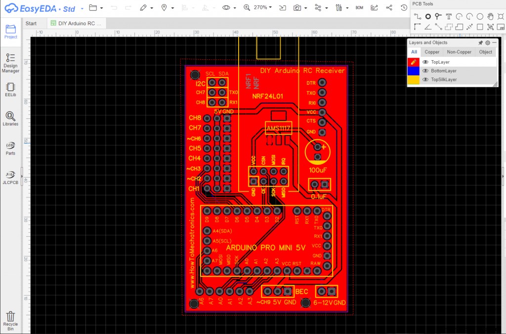
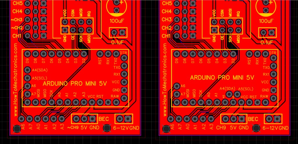
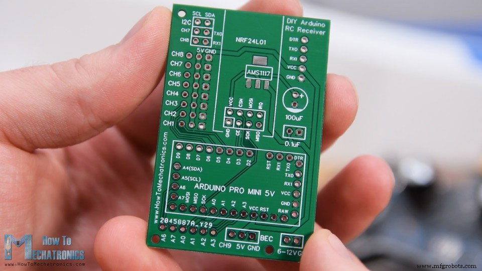
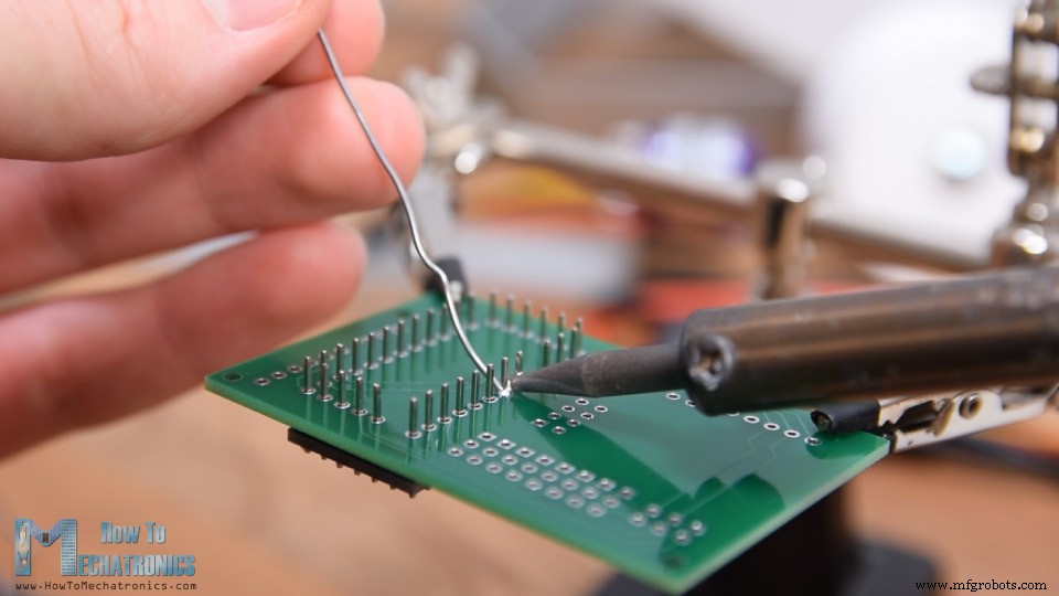
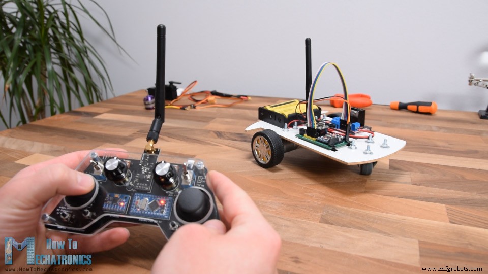
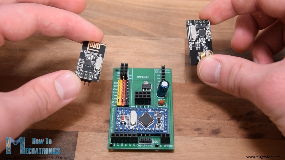
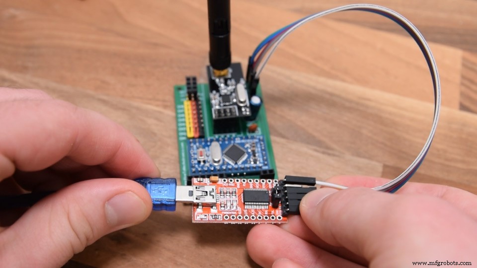
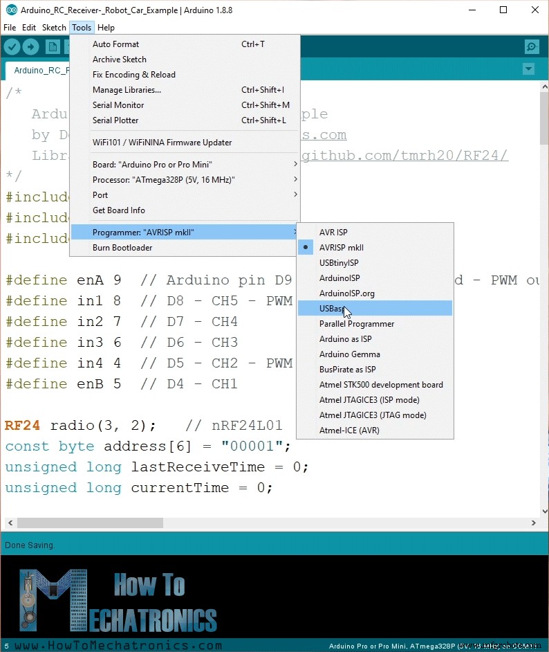
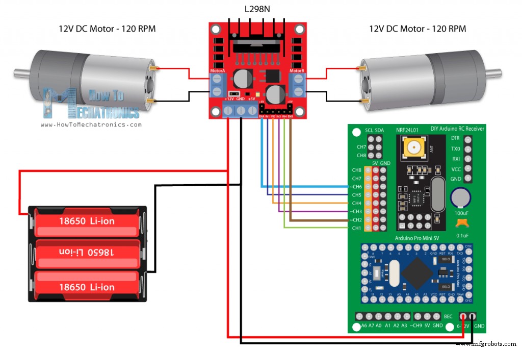
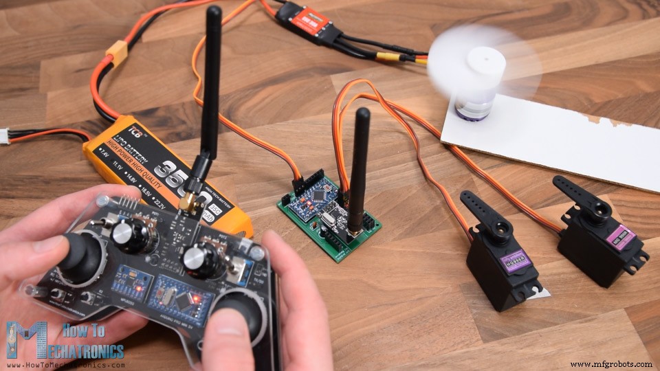
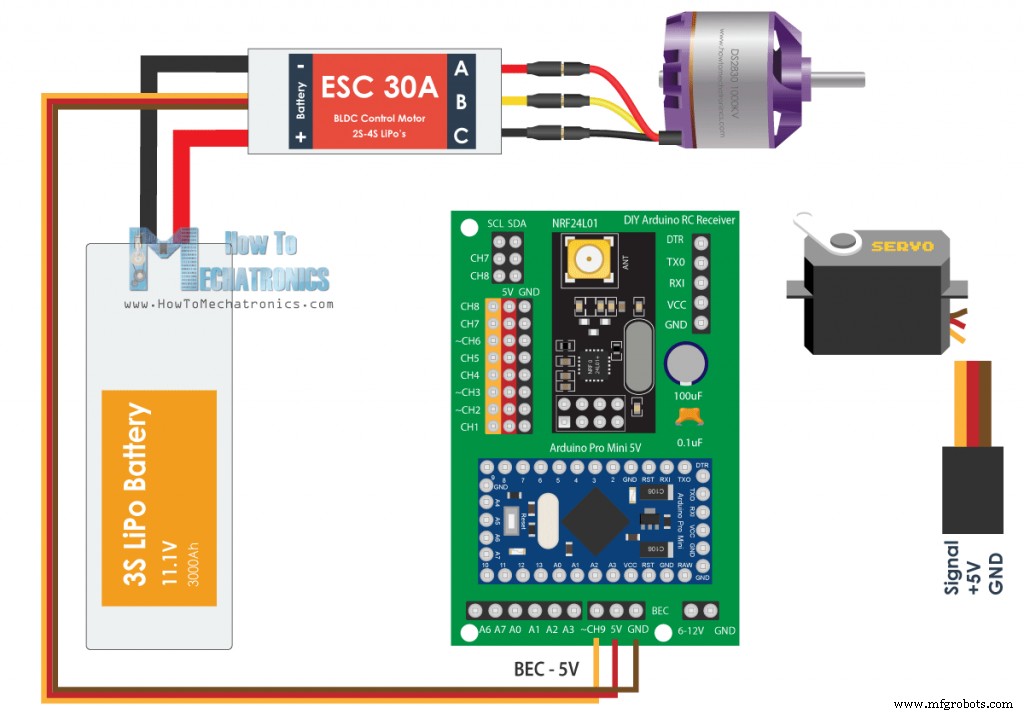
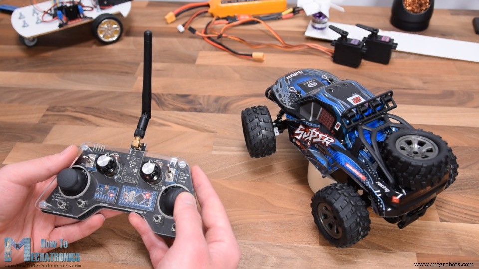
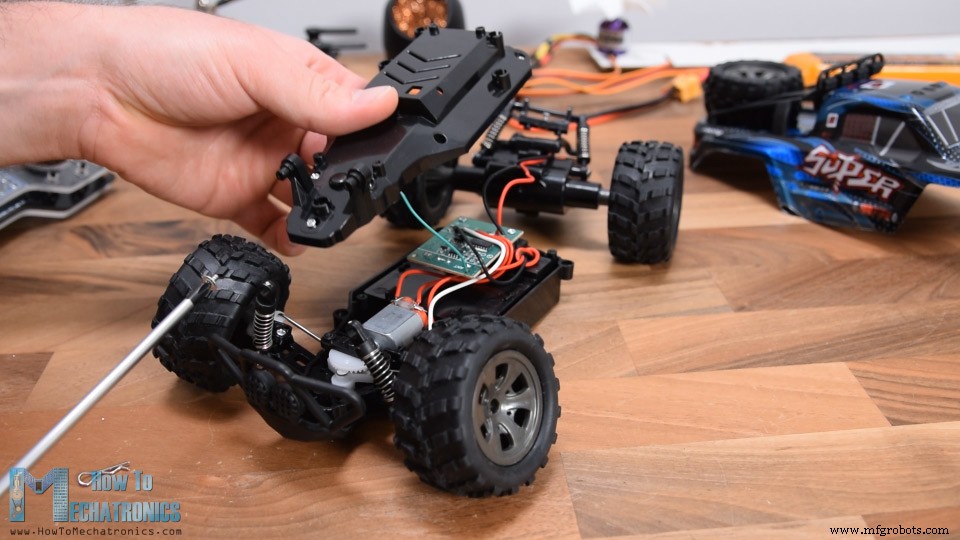
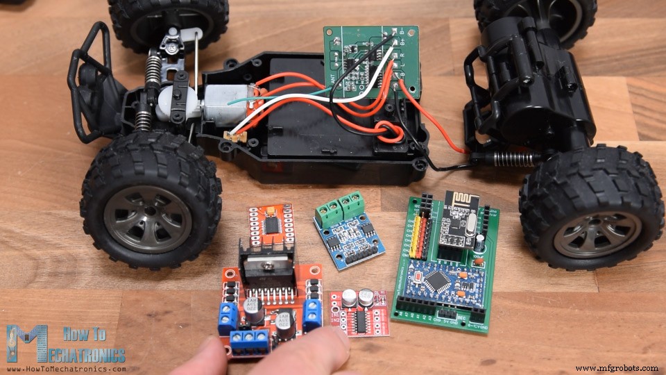
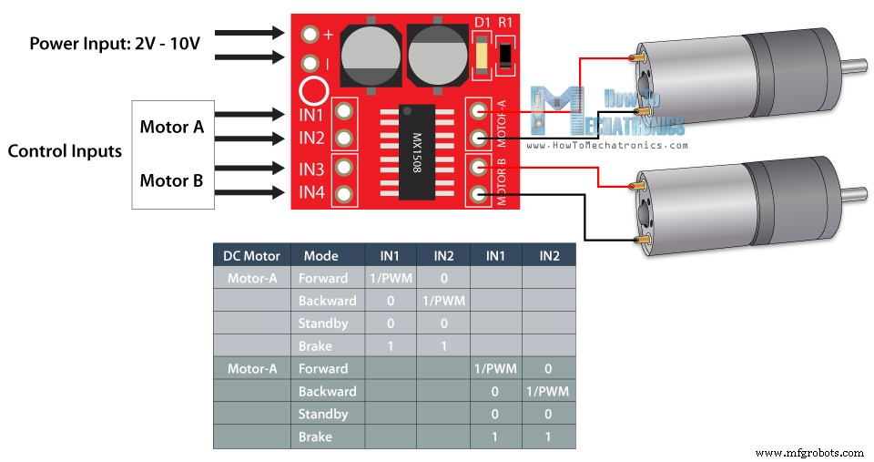
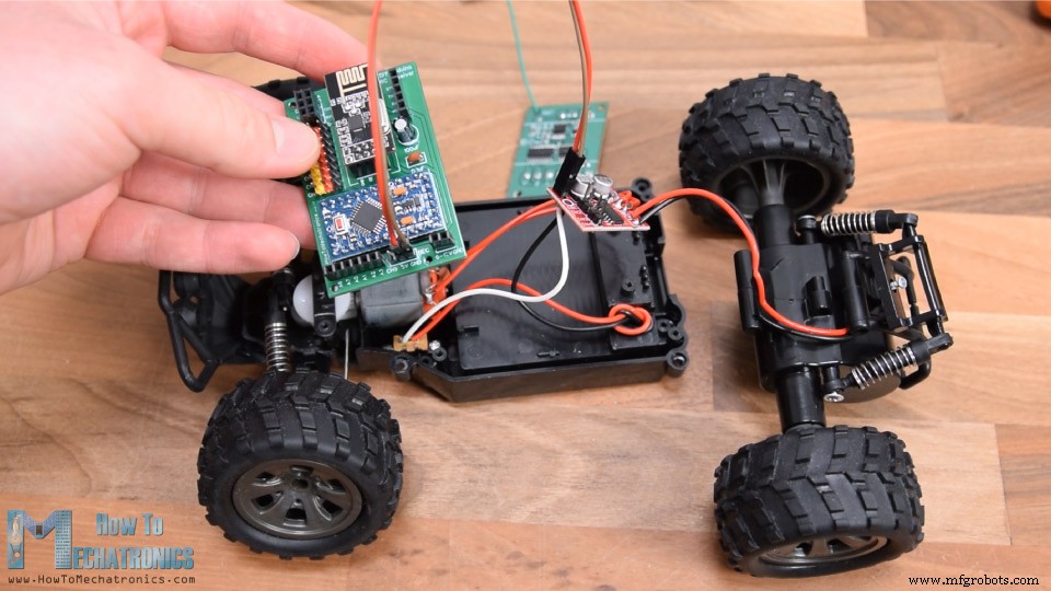
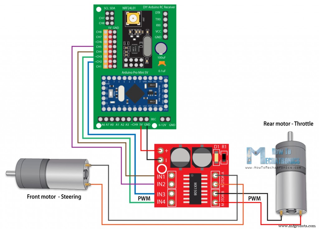
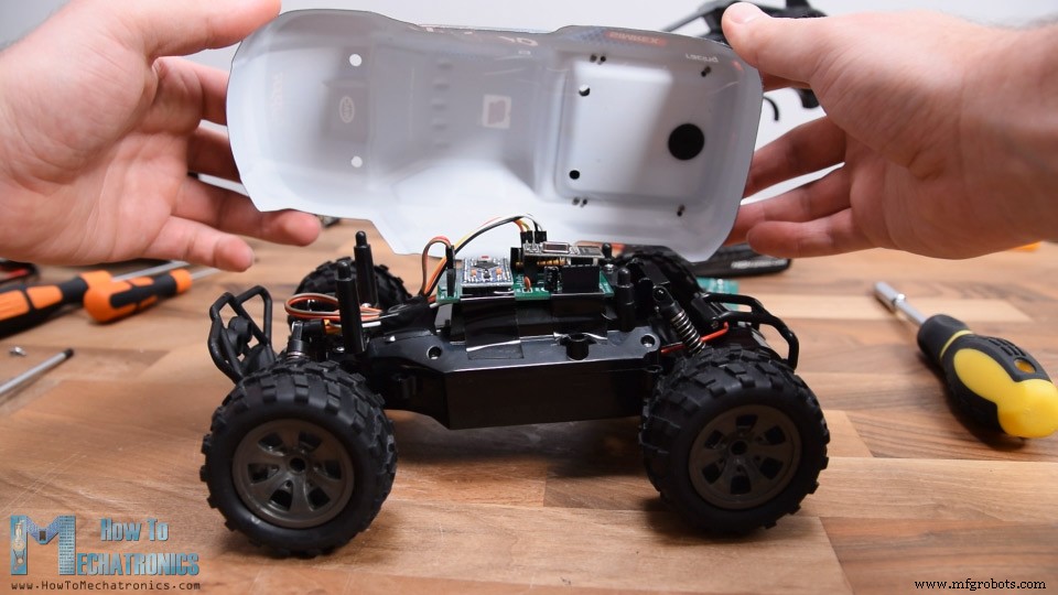
このチュートリアルでは、ArduinoベースのRCレシーバーの作り方を学びます。以前の動画でDIY Arduino RC送信機を作って以来、多くのリクエストをいただき、専用のレシーバーを作成しました。 以下の動画を見るか、書面チュートリアルをお読みください。 この2台のデバイスは簡単に通信でき、様々なものを無線で制御できます。いくつかの例を通じて仕組みを説明します。最初の例では、このArduino RCレシーバーを使って2つのDCモーターで構成されるシンプルなカーを制御します。2つ目の例では、ブラシレスモーターとサーボの制御方法を紹介します。これらは市販のRC飛行機、ボート、カーなどに使われる一般的なコンポーネントです。これらを制御する方法がわかれば、自作のArduino送信機で多くのRC模型を改造・制御できるようになります。 3つ目の例では、このArduinoベースのRCシステムを使って市販のRCカーを改造・制御した方法を紹介します。 まず、このシステムの回路図を見てみましょう。無線通信はNRF24L01トランシーバーモジュールをベースにしています。 送信機はジョイスティック、ボタン、ポテンショメーター、トグルスイッチなどのコントローラーからのデータを常時送信し、レシーバー側でこのデータを受信します。このArduino送信機の詳細については、別の詳しいチュートリアルをご覧ください。 なお、このRCレシーバーは必ずしもこの特定の送信機のみで動作するわけではありません。ArduinoボードとNRF24L01モジュールで構成される類似のセットアップであれば、どれでも動作します。 このRCレシーバーの頭脳はArduino Pro Miniボードです。電源供給には、5Vを接続するVCCピン、または6〜12Vを接続するRAWピンのいずれかを使用できます。Arduino Pro Miniには5V動作版(今回使用)と3.3V動作版の2種類があります。一方、NRF24L01モジュールは3.3Vで動作するため、電圧レギュレーターが必要です。今回はAMS1117 3.3V電圧レギュレーターを使用し、5〜12Vの入力から3.3Vを出力しています。 このArduino RCレシーバーに必要なコンポーネントは以下のリンクから入手できます: NRF24L01モジュールはArduinoとの通信にSPIプロトコルと2つの追加デジタルピンを使用するため、残り9つのデジタルピンを出力チャンネルとして使用できます。うち2つはRX/TXピンです。これらのピンはスケッチのアップロード時に外しておく必要があるため、別のピンヘッダーで着脱可能にしました。また、アナログ入力もデジタル出力として使えるため、この小さなボードでも十分な出力チャンネルが確保できます。 回路をコンパクトにまとめるため、EasyEDA無料オンライン回路設計ソフトでカスタムPCBを作成しました。8チャンネルを5VとGNDレールのすぐ隣に配置し、サーボやESCを直接接続できるようにしています。チャンネル9はArduinoのVCCピン近くに配置し、ESCのBEC(バッテリー・エリミネーター・サーキット)機能で5Vを供給してArduinoを駆動できるようにしています。もちろん、他のチャンネルでもVCCピンは5Vレールに接続されているため同じ目的で使えます。 チャンネル7と8はピンヘッダーで分断されており、使用する場合は2ピンをショートさせます。プログラミング用ヘッダーは右上に、100μFコンデンサーは電圧レギュレーターとNRF24L01の両方に対応しています。PCB左下にはアナログピンを配置しました。 Arduino Pro Miniボードによってピン配置が異なる場合があるため、もう1つバージョンのPCBも用意しています。お手持ちのボードに合う方を選んでください。 このPCBのプロジェクトファイルへのリンクはこちらです。設計完了後、PCB製造用のガーバーファイルを生成しました。 ガーバーファイル: その後、この動画のスポンサーでもあるJLCPCBにPCBを発注しました。 ガーバーファイルをドラッグ&ドロップでアップロードし、ガーバービューアーで確認。問題なければ希望の仕様を選択して発注するだけです。JLCPCBが初めての場合、最大5枚まで2ドルで注文できます。 数日後にPCBが届きました。品質は素晴らしく、設計通りの仕上がりです。 組み立てを始めます。まずArduinoボードのピンヘッダーをはんだ付けします。ブレッドボードにピンヘッダーを刺して固定すると作業しやすいです。ボードによってピン配置が微妙に異なる場合があるので注意してください。 PCB裏面に配線が通っているGNDピンは空けておく必要があります。Arduinoボードをはんだ付け後、ピンの余分な部分をカットしました。 続いて他のピンヘッダーを配置・はんだ付けします。オス・メスどちらでも構いませんが、サーボやESCのコネクターがメスなので、デジタルチャンネル側はオスピンヘッダーにすると接続しやすいです。 電圧レギュレーターは表面実装部品なので、ブルータックで固定してはんだ付けしました。最後に2つのコンデンサーをはんだ付けし、NRF24L01モジュールを適切なピンヘッダーに取り付けます。 用途や必要な通信距離に応じて、オンボードアンテナの標準モジュールか、大型アンテナ装着可能な高出力モジュール(PA+LNA)を選べます。後者は開放地で最大700メートルの通信が可能です。これでArduino RCレシーバーの完成です。 プログラミングやPC接続には、USB-シリアルUARTインターフェースをプログラミングヘッダーに接続して使用します。 Arduino IDEのツールメニューで「Arduino Pro or Pro Mini」ボードを選択、プロセッサーのバージョンを選択、ポートを選択、書き込み装置を「USBasp」に設定します。 これでスケッチをアップロードできるようになります。 最初の例を見てみましょう。 2つの12V DCモーターで構成されるシンプルなカーです。以前の動画で作り方と仕組みを紹介しています。 関連記事:L298Nモータードライバー – Arduinoインターフェース、仕組み、コード、回路図 今回は新しいArduino RCレシーバーで制御します。DCモーターの駆動にはL298Nモータードライバーを使用し、電源には3つのリチウムイオン電池(約12V)を使います。 この例に必要なコンポーネント: 接続はシンプルです。電池からの12Vをレシーバーの12Vピンに、ドライバーの6つの制御ピンを6チャンネルに接続します。モーターの速度制御にはドライバーのENA/ENBピンにPWM信号を入力する必要があります。このレシーバーではチャンネル2、3、6、9がPWM出力可能なので、ENAをチャンネル2、ENBをチャンネル6に接続しました。 Arduinoコードを見てみましょう。 解説: まずSPIライブラリとRF24ライブラリをインクルードし、ピン定義、無線オブジェクト、送信機から受信するデータ構造体を定義します。setup()ではピンの出力設定と無線通信の初期化を行います。詳細についてはNRF24L01の詳しいチュートリアルをご覧ください。 loop()では常時データ受信をチェックし、データがあれば読み取ります。送信機のコードを見ると、ジョイスティック、ポテンショメーター、ボタンなど全コントローラーのデータを1つのパッケージとして送信していることがわかります。 受信データを読み取った後、用途に応じて処理します。ここではジョイスティック1のY軸をスロットル(前進/後退)、X軸をステアリング(左右)に割り当てています。ジョイスティックの値は0〜255です。下方向(110未満)なら後退、上方向(140超)なら前進、中央付近なら停止とし、map()関数でPWM値(0〜255)に変換しています。ステアリングも同様に、左右のモーター速度を差動制御して旋回させます。コード末尾のresetData()関数は、通信途絶時に全値を初期値に戻し、意図しない動作を防ぎます。 次に、サーボとブラシレスモーターの制御例です。 ブラシレスモーターの制御にはESC(電子スピードコントローラー)が必要です。Arduinoは1本のピンでESCと通信し、特定のPWM信号を送ってモーター回転数を制御します。同じ接続でESCのBEC機能から5Vが供給されるため、レシーバーの電源としても利用できます。 関連記事:Arduinoブラシレスモーター制御チュートリアル | ESC | BLDC サーボモーターも同じタイプの接続で、利用可能なチャンネルに直接接続できます。 この例に必要なコンポーネント: サーボとESCの入力信号はほぼ同じで、50Hzの特定PWM信号を使用します。これはArduinoのServoライブラリで簡単に生成できます。 注意: このセットアップでMG996Rサーボを使用すると、回路に問題が生じArduino Pro Miniが焼損する可能性があります。大電流を引くため5Vレールで電圧スパイクが発生し、Arduino Pro Miniの5Vピン耐圧(5.5Vまで)を超える恐れがあります。実際にテスト時にこの問題が発生し、コメント欄でも報告されています。対策としてサーボに大容量のデカップリングコンデンサーを追加する方法が考えられますが、未検証です。ご注意ください。 一方、別のMG996Rサーボ2個では問題なく動作しました(スパイクが小さかったと思われます)。また、より小型のS90サーボ4個でも問題ありませんでした。 関連記事:サーボモーターの仕組みとArduinoでの制御方法 受信データ(0〜255)を、サーボ制御用の0〜180度にmap()で変換し、write()関数で出力します。ESCも同様に、ジョイスティック1のY軸中央(127)〜上(255)を1000〜2000マイクロ秒に変換し、writeMicroseconds()でPWM信号を送信してブラシレスモーターを最小〜最大速度で制御します。 関連記事:Arduino RC飛行機 | 100% DIY このように、RC飛行機、カー、ボートなどは通常サーボとブラシレスモーターを使用するため、この方法で制御できます。 このRCカーには専用コントローラーが付属し、前輪の左右操舵と前後進が可能です。 しかし安価なRCカーのため、制御はデジタル(オン/オフのみ)で、最大舵角・最大速度のみでした。分解して内部を見てみると、2つのモーターはともに5V動作のシンプルなDCモーターでした。操舵用のフロントモーターも連続回転型のDCモーターです。 DCモーターの制御方法はすでにわかっているため、この基板を自作Arduinoレシーバーに置き換えるのは容易です。レシーバーに加えて、2モーター同時駆動可能なモータードライバーが必要です。選択肢は多数あり、例1で使用したL298Nドライバーも使えます。 ただしL298Nはこの用途には大きすぎるため、MX1508モータードライバーを選びました。これはHブリッジとPWM制御を備えたシンプルなデュアルDCモータードライバーで、制御入力4ピン、モーター出力4ピン、電源2ピンを持ちます。 RCカー基板からモーター配線を外し、ドライバーにはんだ付け。裏面に電源ピンをはんだ付けし、ドライバーとレシーバーを接続します。電源は車体底部の4.8V Ni-Cdバッテリーです。 ジャンパーワイヤーでバッテリーをArduinoのVCCピンに、ドライバーの4制御入力ピンを4つのデジタルチャンネルに接続。このドライバーはPWM制御対応なので、リアモーター(モーターB)用にPWM対応のチャンネル2と3を使用しました。 この例に必要なコンポーネント: このRCカーのコードは例1と非常に似ています。 ジョイスティックデータでスロットルとステアリングを制御します。後退時はanalogWrite()で入力3にPWM信号を送り入力4をLOW、前進時はその逆。中央では両入力をHIGHにしてブレーキ/停止させます。ステアリングモーターも同様ですが、速度制御不要なのでanalogWrite()は使いません。 スケッチをアップロード後、RCカーを再組み立て。小型ドライバーを内部に収め、ネジで固定。レシーバーとドライバーを再接続し、外装の下にレシーバーを収納しました。 自作RC送信機で制御できるようになっただけでなく、PWM制御により速度調整も可能になり改良されています。改造対象のRC模型がDCモーターではなくサーボとブラシレスモーターを使用している場合は、例2の方法を参考にしてください。 このチュートリアルがお役に立てば幸いです。質問はコメント欄でどうぞ。Arduinoプロジェクトコレクションもご覧ください。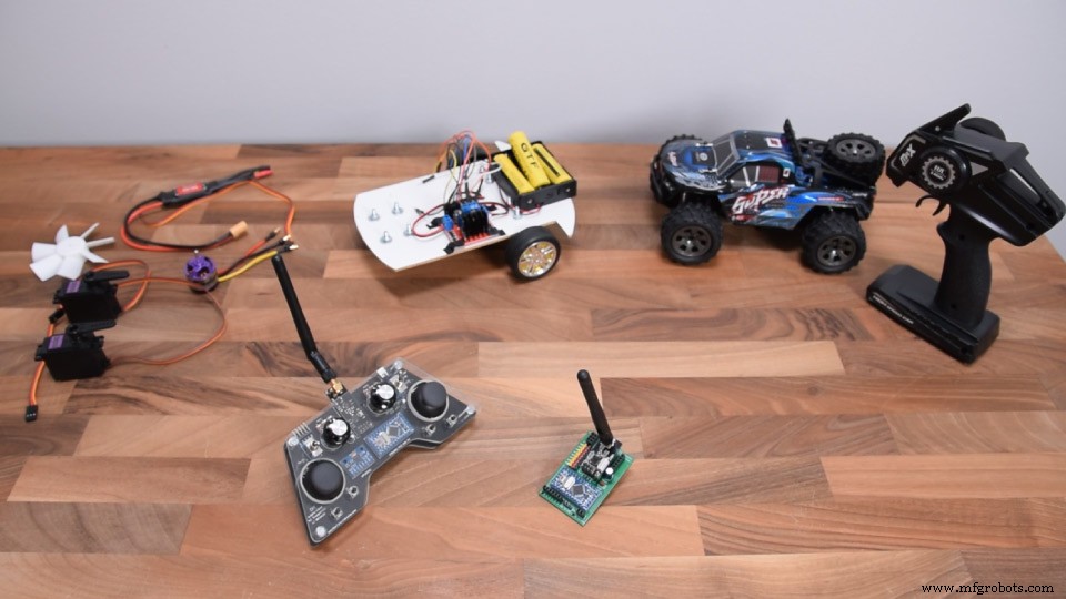
Arduino RCレシーバーの回路図
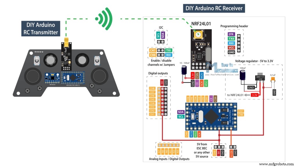
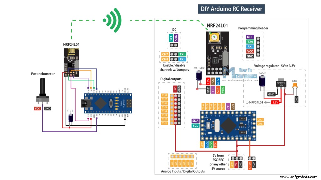
PCB設計
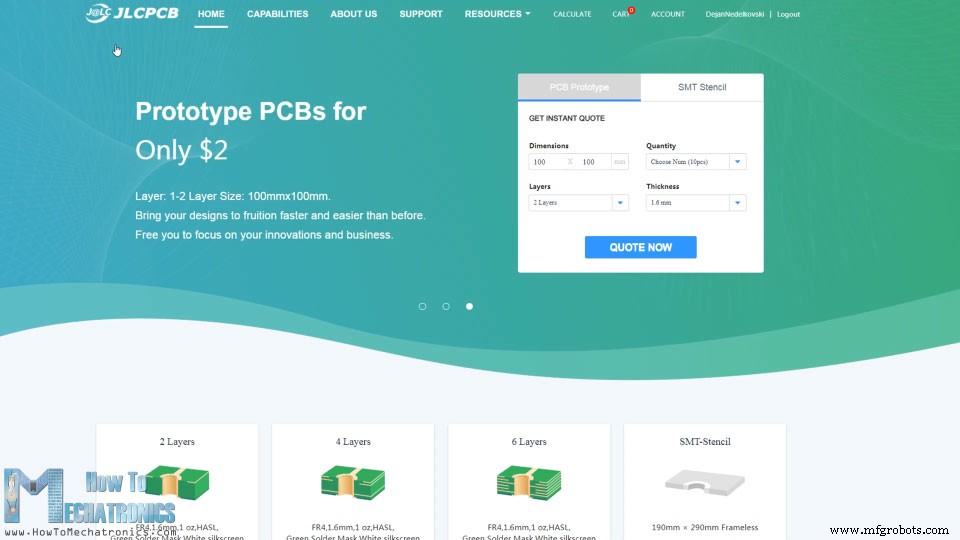
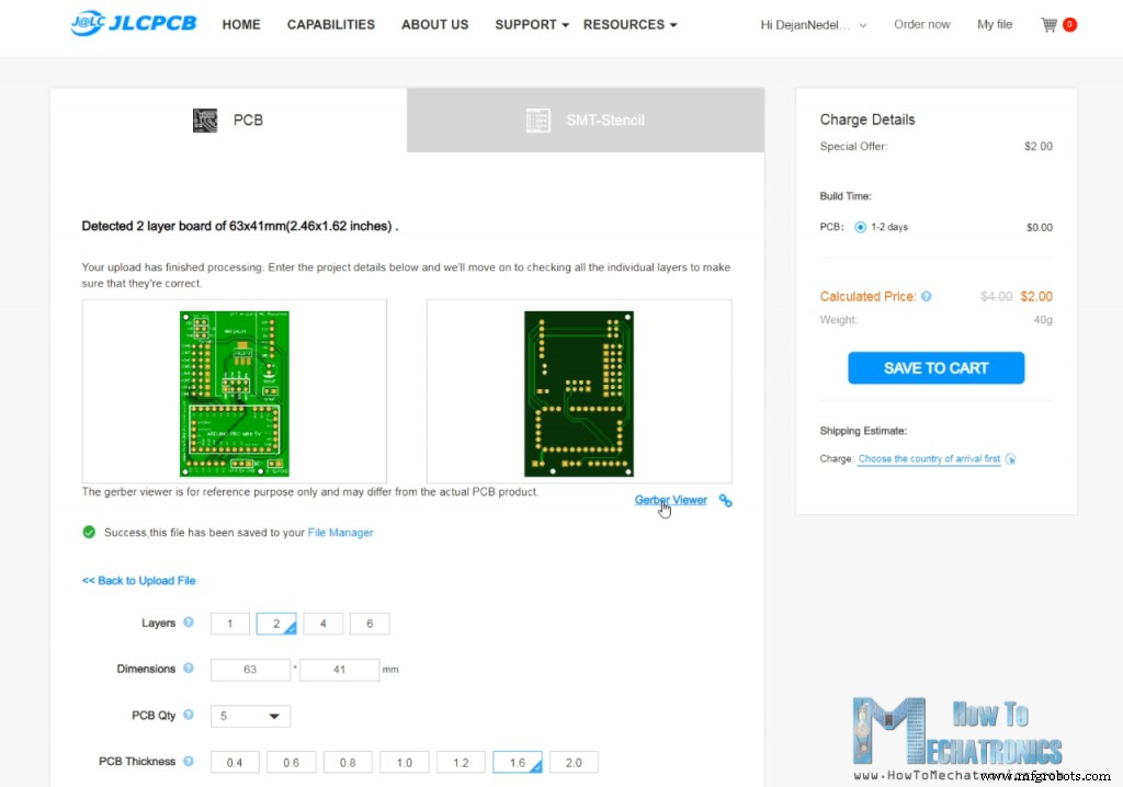
PCB組み立て
例1 – Arduino RCカー
/* Arduino RC Receiver - Car Example by Dejan, www.HowToMechatronics.com Library: TMRh20/RF24, https://github.com/tmrh20/RF24/ */
#include <SPI.h>
#include <nRF24L01.h>
#include <RF24.h>
#define enA 9 // Arduino pin D9 - CH6 on PCB board - PWM output
#define in1 8 // D8 - CH5
#define in2 7 // D7 - CH4
#define in3 6 // D6 - CH3
#define in4 4 // D4 - CH1
#define enB 5 // D5 - CH2 - PWM output
RF24 radio(3, 2); // nRF24L01 (CE, CSN)
const byte address[6] = "00001";
unsigned long lastReceiveTime = 0;
unsigned long currentTime = 0;
// Max size of this struct is 32 bytes
struct Data_Package {
  byte j1PotX;
  byte j1PotY;
  byte j1Button;
  byte j2PotX;
  byte j2PotY;
  byte j2Button;
  byte pot1;
  byte pot2;
  byte tSwitch1;
  byte tSwitch2;
  byte button1;
  byte button2;
  byte button3;
  byte button4;
};
Data_Package data; //Create a variable with the above structure
int steering, throttle;
int motorSpeedA = 0;
int motorSpeedB = 0;
void setup() {
  pinMode(enA, OUTPUT);
  pinMode(enB, OUTPUT);
  pinMode(in1, OUTPUT);
  pinMode(in2, OUTPUT);
  pinMode(in3, OUTPUT);
  pinMode(in4, OUTPUT);
  //Serial.begin(9600);
  radio.begin();
  radio.openReadingPipe(0, address);
  radio.setAutoAck(false);
  radio.setDataRate(RF24_250KBPS);
  radio.setPALevel(RF24_PA_LOW);
  radio.startListening(); // Set the module as receiver
  resetData();
}
void loop() {
  // Check whether we keep receving data, or we have a connection between the two modules
  currentTime = millis();
  if ( currentTime - lastReceiveTime > 1000 ) {
    // If current time is more then 1 second since we have recived the last data, that means we have lost connection
    resetData(); // If connection is lost, reset the data. It prevents unwanted behavior
  }
  // Check whether there is data to be received
  if (radio.available()) {
    radio.read(&data, sizeof(Data_Package)); // Read the whole data and store it into the 'data' structure
    lastReceiveTime = millis(); // At this moment we have received the data
  }
  // Parse the data from the Joystic 1 to the throttle and steering variables
  throttle = data.j1PotY;
  steering = data.j1PotX;
  // Throttle used for forward and backward control
  // Joystick values: 0 to 255; down = 0; middle = 127; up = 255
  if (throttle < 110) {
    // Set Motor A backward
    digitalWrite(in1, HIGH);
    digitalWrite(in2, LOW);
    // Set Motor B backward
    digitalWrite(in3, HIGH);
    digitalWrite(in4, LOW);
    // Convert the declining throttle readings for going backward from 110 to 0 into 0 to 255 value for the PWM signal
    motorSpeedA = map(throttle, 110, 0, 0, 255);
    motorSpeedB = map(throttle, 110, 0, 0, 255);
  } else if (throttle > 140) {
    // Set Motor A forward
    digitalWrite(in1, LOW);
    digitalWrite(in2, HIGH);
    // Set Motor B forward
    digitalWrite(in3, LOW);
    digitalWrite(in4, HIGH);
    // Convert the increasing throttle readings for going forward from 140 to 255 into 0 to 255 value for the PWM signal
    motorSpeedA = map(throttle, 140, 255, 0, 255);
    motorSpeedB = map(throttle, 140, 255, 0, 255);
  }
  // If joystick stays in middle the motors are not moving
  else {
    motorSpeedA = 0;
    motorSpeedB = 0;
  }
  // Steering used for left and right control
  if (steering < 110) {
    // Convert the declining steering readings from 110 to 0 into increasing 0 to 255 value
    int xMapped = map(steering, 110, 0, 0, 255);
    // Move to left - decrease left motor speed, increase right motor speed
    motorSpeedA = motorSpeedA - xMapped;
    motorSpeedB = motorSpeedB + xMapped;
    // Confine the range from 0 to 255
    if (motorSpeedA < 0) { motorSpeedA = 0; }
    if (motorSpeedB > 255) { motorSpeedB = 255; }
  }
  if (steering > 140) {
    // Convert the increasing steering readings from 140 to 255 into 0 to 255 value
    int xMapped = map(steering, 140, 255, 0, 255);
    // Move right - decrease right motor speed, increase left motor speed
    motorSpeedA = motorSpeedA + xMapped;
    motorSpeedB = motorSpeedB - xMapped;
    // Confine the range from 0 to 255
    if (motorSpeedA > 255) { motorSpeedA = 255; }
    if (motorSpeedB < 0) { motorSpeedB = 0; }
  }
  // Prevent buzzing at low speeds (Adjust according to your motors. My motors couldn't start moving if PWM value was below value of 70)
  if (motorSpeedA < 70) { motorSpeedA = 0; }
  if (motorSpeedB < 70) { motorSpeedB = 0; }
  analogWrite(enA, motorSpeedA); // Send PWM signal to motor A
  analogWrite(enB, motorSpeedB); // Send PWM signal to motor B
}
void resetData() {
  // Reset the values when there is no radio connection - Set initial default values
  data.j1PotX = 127;
  data.j1PotY = 127;
  data.j2PotX = 127;
  data.j2PotY = 127;
  data.j1Button = 1;
  data.j2Button = 1;
  data.pot1 = 1;
  data.pot2 = 1;
  data.tSwitch1 = 1;
  data.tSwitch2 = 1;
  data.button1 = 1;
  data.button2 = 1;
  data.button3 = 1;
  data.button4 = 1;
}例2 – Arduino RCレシーバーによるサーボとブラシレスモーターの制御
/* DIY RC Receiver - Servos and Brushless motors control by Dejan, www.HowToMechatronics.com Library: TMRh20/RF24, https://github.com/tmrh20/RF24/ */
#include <SPI.h>
#include <nRF24L01.h>
#include <RF24.h>
#include <Servo.h>
RF24 radio(3, 2); // nRF24L01 (CE, CSN)
const byte address[6] = "00001";
unsigned long lastReceiveTime = 0;
unsigned long currentTime = 0;
Servo esc; // create servo object to control the ESC
Servo servo1;
Servo servo2;
int escValue, servo1Value, servo2Value;
// Max size of this struct is 32 bytes - NRF24L01 buffer limit
struct Data_Package {
  byte j1PotX;
  byte j1PotY;
  byte j1Button;
  byte j2PotX;
  byte j2PotY;
  byte j2Button;
  byte pot1;
  byte pot2;
  byte tSwitch1;
  byte tSwitch2;
  byte button1;
  byte button2;
  byte button3;
  byte button4;
};
Data_Package data; //Create a variable with the above structure
void setup() {
  Serial.begin(9600);
  radio.begin();
  radio.openReadingPipe(0, address);
  radio.setAutoAck(false);
  radio.setDataRate(RF24_250KBPS);
  radio.setPALevel(RF24_PA_LOW);
  radio.startListening(); // Set the module as receiver
  resetData();
  esc.attach(10); // Arduino digital pin D10 - CH9 on PCB board
  servo1.attach(4); // D4 - CH1
  servo2.attach(5); // D5 - CH2
}
void loop() {
  // Check whether we keep receving data, or we have a connection between the two modules
  currentTime = millis();
  if ( currentTime - lastReceiveTime > 1000 ) {
    // If current time is more then 1 second since we have recived the last data, that means we have lost connection
    resetData(); // If connection is lost, reset the data. It prevents unwanted behavior
  }
  // Check whether there is data to be received
  if (radio.available()) {
    radio.read(&data, sizeof(Data_Package)); // Read the whole data and store it into the 'data' structure
    lastReceiveTime = millis(); // At this moment we have received the data
  }
  // Controlling servos
  servo1Value = map(data.j2PotX, 0, 255, 0, 180); // Map the receiving value form 0 to 255 to 0 to 180(degrees), values used for controlling servos
  servo2Value = map(data.j2PotY, 0, 255, 0, 180);
  servo1.write(servo1Value);
  servo2.write(servo2Value);
  // Controlling brushless motor with ESC
  escValue = map(data.j1PotY, 127, 255, 1000, 2000); // Map the receiving value form 127 to 255 to 1000 to 2000, values used for controlling ESCs
  esc.writeMicroseconds(escValue); // Send the PWM control singal to the ESC
}
void resetData() {
  // Reset the values when there is no radio connection - Set initial default values
  data.j1PotX = 127;
  data.j1PotY = 127;
  data.j2PotX = 127;
  data.j2PotY = 127;
  data.j1Button = 1;
  data.j2Button = 1;
  data.pot1 = 1;
  data.pot2 = 1;
  data.tSwitch1 = 1;
  data.tSwitch2 = 1;
  data.button1 = 1;
  data.button2 = 1;
  data.button3 = 1;
  data.button4 = 1;
}例3 – RCカーモデルの制御
/* Arduino RC Receiver - RC Model control by Dejan , www.HowToMechatronics.com Library: TMRh20/RF24, https://github.com/tmrh20/RF24/ */
#include <SPI.h>
#include <nRF24L01.h>
#include <RF24.h>
#define in3 5 // D5 - CH2 - PWM output
#define in4 6 // D6 - CH3 - PWM output
#define in1 7 // D7 - CH4
#define in2 8 // D8 - CH5
RF24 radio(3, 2); // nRF24L01 (CE, CSN)
const byte address[6] = "00001";
unsigned long lastReceiveTime = 0;
unsigned long currentTime = 0;
// Max size of this struct is 32 bytes
struct Data_Package {
  byte j1PotX;
  byte j1PotY;
  byte j1Button;
  byte j2PotX;
  byte j2PotY;
  byte j2Button;
  byte pot1;
  byte pot2;
  byte tSwitch1;
  byte tSwitch2;
  byte button1;
  byte button2;
  byte button3;
  byte button4;
};
Data_Package data; //Create a variable with the above structure
int steering, throttle;
int motorSpeedA = 0;
int motorSpeedB = 0;
void setup() {
  pinMode(in1, OUTPUT);
  pinMode(in2, OUTPUT);
  pinMode(in3, OUTPUT);
  pinMode(in4, OUTPUT);
  Serial.begin(9600);
  radio.begin();
  radio.openReadingPipe(0, address);
  radio.setAutoAck(false);
  radio.setDataRate(RF24_250KBPS);
  radio.setPALevel(RF24_PA_LOW);
  radio.startListening(); // Set the module as receiver
  resetData();
}
void loop() {
  // Check whether we keep receving data, or we have a connection between the two modules
  currentTime = millis();
  if ( currentTime - lastReceiveTime > 1000 ) {
    // If current time is more then 1 second since we have recived the last data, that means we have lost connection
    resetData(); // If connection is lost, reset the data. It prevents unwanted behavior
  }
  // Check whether there is data to be received
  if (radio.available()) {
    radio.read(&data, sizeof(Data_Package)); // Read the whole data and store it into the 'data' structure
    lastReceiveTime = millis(); // At this moment we have received the data
  }
  // Parse the data from the Joystic 1 to the steering and throttle variables
  steering = data.j2PotX;
  throttle = data.j1PotY;
  // Throttle used for forward and backward control
  if (throttle < 110) {
    // Convert the declining throttle readings for going backward from 110 to 0 into 0 to 255 value for the PWM signal
    motorSpeedB = map(throttle, 110, 0, 0, 255);
    // Set Motor B backward
    analogWrite(in3, motorSpeedB);
    digitalWrite(in4, LOW);
  } else if (throttle > 140) {
    // Convert the increasing throttle readings for going forward from 140 to 255 into 0 to 255 value for the PWM signal
    motorSpeedB = map(throttle, 140, 255, 0, 255);
    // Set Motor B forward
    digitalWrite(in3, LOW);
    analogWrite(in4, motorSpeedB);
  }
  // If joystick stays in middle the motors are not moving
  else {
    digitalWrite(in3, HIGH);
    digitalWrite(in4, HIGH);
  }
  // steering used for left and right control
  if (steering < 110) {
    digitalWrite(in1, HIGH);
    digitalWrite(in2, LOW);
  }
  if (steering > 140) {
    digitalWrite(in1, LOW);
    digitalWrite(in2, HIGH);
  }
  // If joystick stays in middle the motors are not moving
  else {
    digitalWrite(in1, HIGH);
    digitalWrite(in2, HIGH);
  }
}
void resetData() {
  // Reset the values when there is no radio connection - Set initial default values
  data.j1PotX = 127;
  data.j1PotY = 127;
  data.j2PotX = 127;
  data.j2PotY = 127;
  data.j1Button = 1;
  data.j2Button = 1;
  data.pot1 = 1;
  data.pot2 = 1;
  data.tSwitch1 = 1;
  data.tSwitch2 = 1;
  data.button1 = 1;
  data.button2 = 1;
  data.button3 = 1;
  data.button4 = 1;
}
製造プロセス
- DIY自家醸造温度制御:Arduinoで監視・調節
- 実験室・科学実験向け精密熱電対測定とロギング
- Arduino UNOで作るLCDアニメーション&ゲーム入門
- Arduinoとスマホで作るスマート電圧計 – 簡単DIYプロジェクト
- ArduinoとNokia 5110ディスプレイで自作電圧計:ステップバイステップガイド
- Python 3からArduino UNOを制御 – シリアル通信でLED点滅デモ
- Arduino NanoとRDA5807Mで作るコンパクトFMラジオ
- CADモデルが金属加工プロジェクトの成功を導く理由
- MKR1000ピン配置完全解説:IoT開発に最適なArduinoボード
- CNCルーター vs CNCレーザーカッター:DIYクラフトプロジェクトに最適なのはどっち?
- Twisterスピード旋盤:50%パワーアップと再生制御で先進研磨・バリ取り