


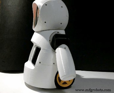
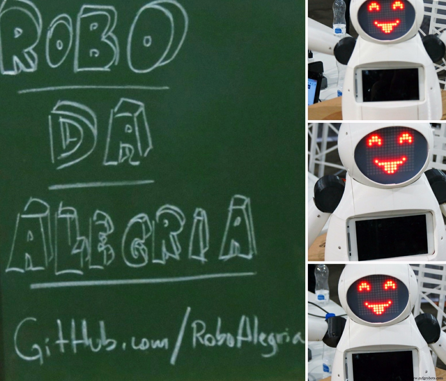
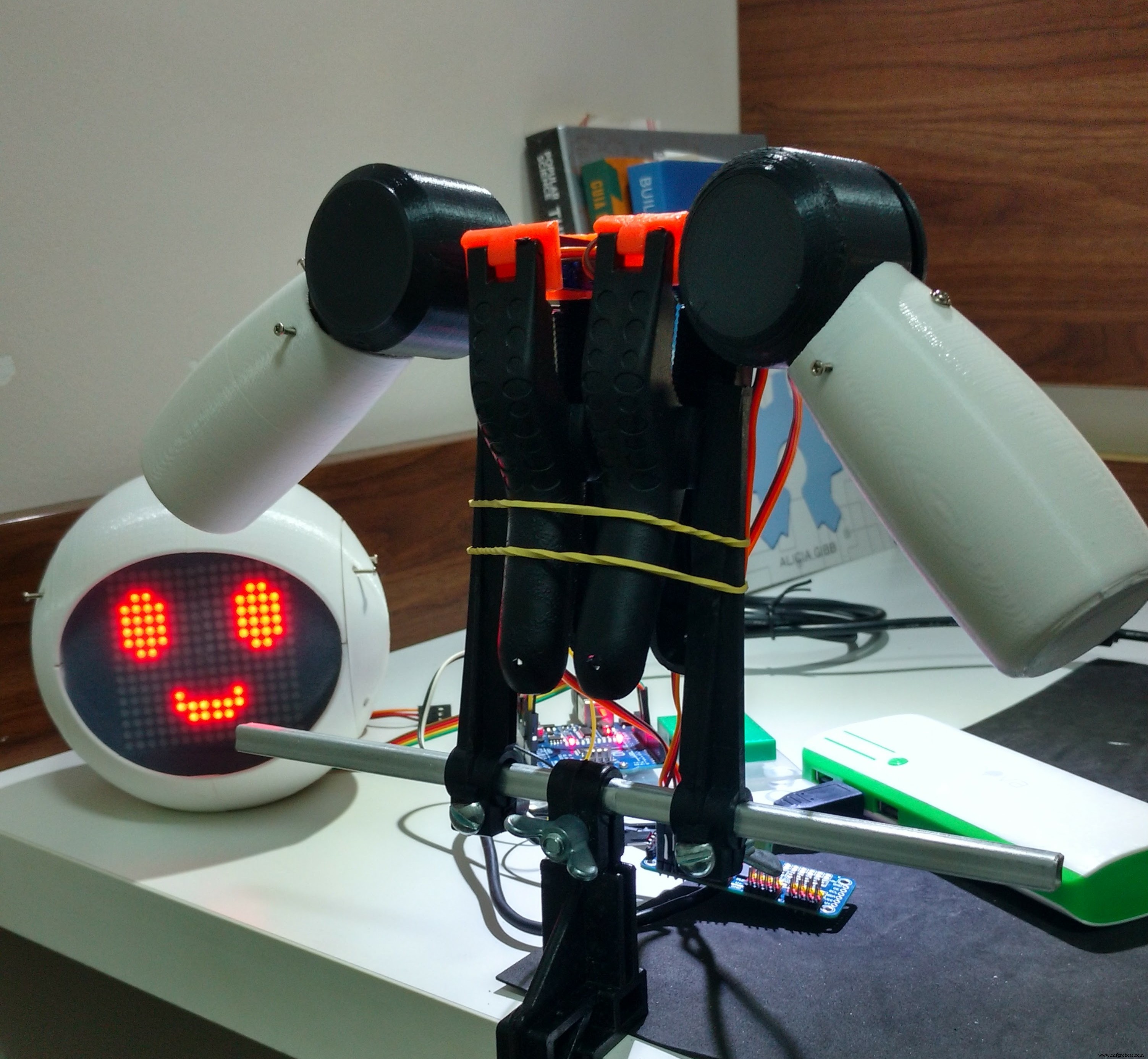
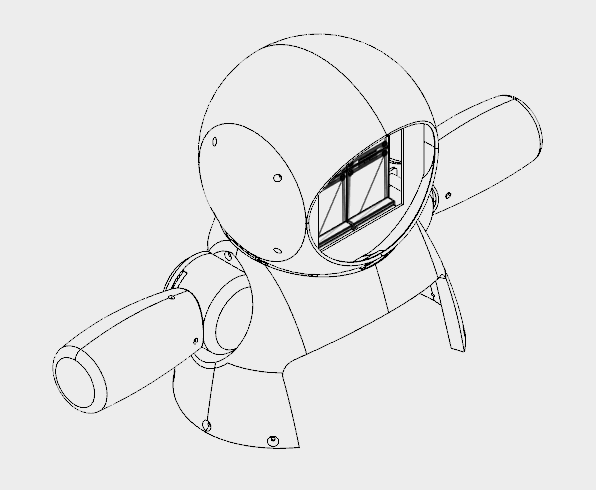
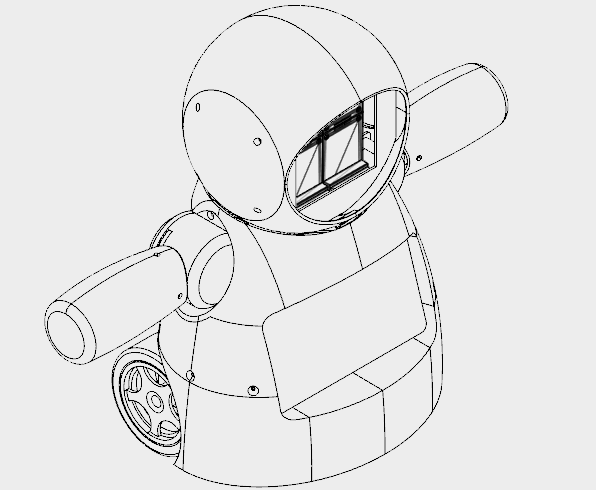
Joy Robot(RobôDaAlegria)
コンポーネントと消耗品
>  |
| × | 1 | |||
 |
| × | 1 | |||
 |
| × | 6 | |||
| × | 2 | ||||
| × | 1 | ||||
| × | 1 | ||||
| × | 4 | ||||
 |
| × | 1 | |||
| × | 2 | ||||
| × | 2 | ||||
 |
| × | 1 | |||
| × | 1 | ||||
 |
| × | 3 |
必要なツールとマシン
| ||||
 |
|
アプリとオンラインサービス
>  |
| |||
 |
| |||
|
このプロジェクトについて
Instructables Wheelコンテストで1位、Instructables Arduinoコンテストで2位、Instructables Design for KidsChallengeで2位になりました。私たちに投票してくれたすべての人に感謝します!!!
http://www.instructables.com/id/Joy-Robot-Rob%C3%B4-Da-Alegria-Open-Source-3D-Printed-A/
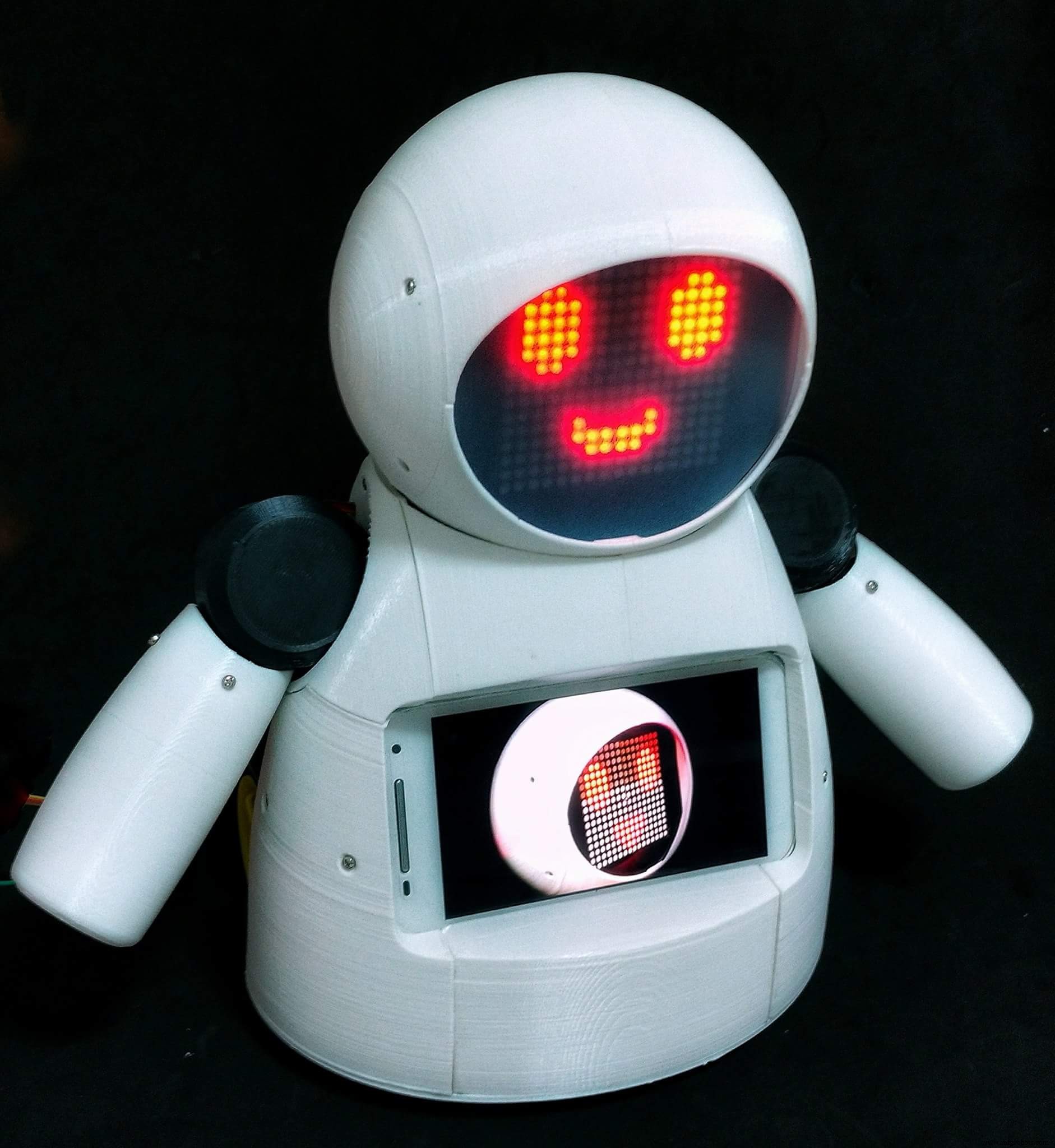
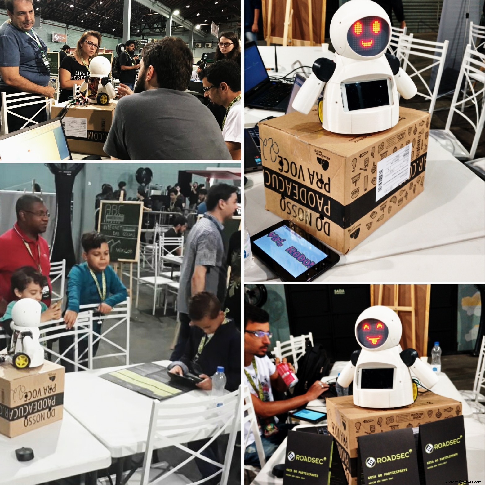
ロボットはいたるところにあります。産業用途から水中および宇宙探査まで。しかし、私のお気に入りは楽しさと娯楽のために使われるものです!このプロジェクトでは、DIYロボットが小児病院での娯楽に使用されるように設計されており、子供たちに楽しみをもたらしています。このプロジェクトは、小児病院で慈善活動を行うNGOを支援するために、知識の共有と技術革新の促進に重点を置いています。
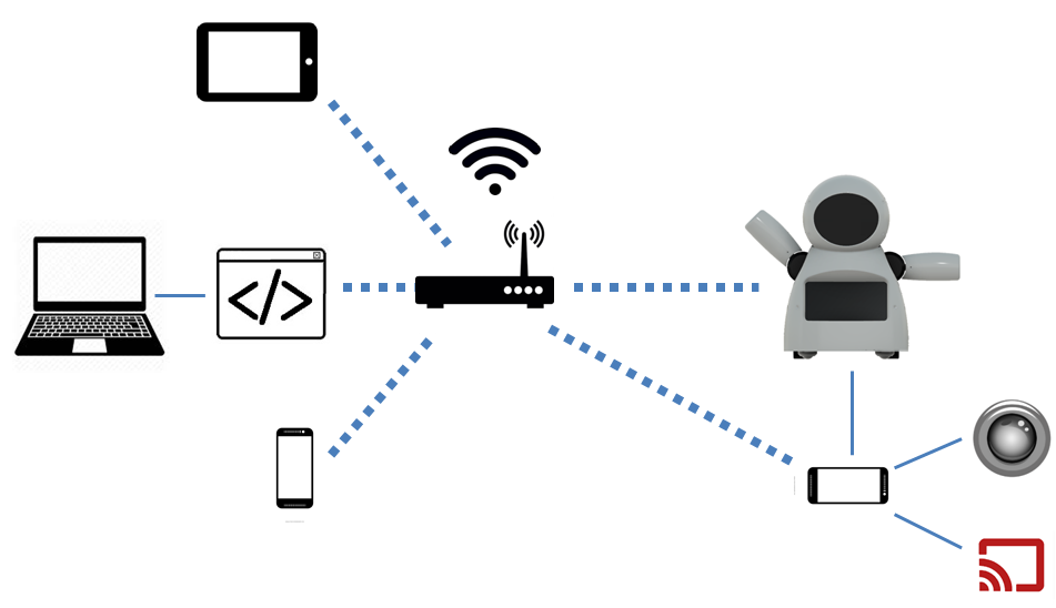
このチュートリアルでは、ESP8266Wi-Fiモジュールに接続されたArduinoUnoを使用して、Wi-Fiネットワークを介して制御される遠隔操作のヒューマノイドロボットを設計する方法を示します。それは、頭と腕の動きを形成するいくつかのサーボモーター、小さな距離を動かすためのいくつかのDCモーター、およびLEDマトリックスで作られた面を使用します。ロボットは、HTMLで設計されたインターフェイスを使用して、通常のインターネットブラウザから制御できます。 Androidスマートフォンは、ロボットからオペレーターの制御インターフェースにビデオとオーディオをブロードキャストするために使用されます。
チュートリアルでは、ロボットの構造を3Dプリントして組み立てた方法を示します。電子回路について説明し、Arduinoコードを詳しく説明しているので、誰でもロボットを複製できます。
このロボットに使用されている技術のいくつかは、すでにチュートリアルで公開されています。次のチュートリアルをご覧ください:
- https://www.instructables.com/id/WiDC-Wi-Fi-Controlled-FPV-Robot-with-Arduino-ESP82/
- https://www.instructables.com/id/Controlling-a-LED-Matrix-Array-With-Arduino-Uno/
- https://www.instructables.com/id/Wi-Servo-Wi-fi-Browser-Controlled-Servomotors-with/
このチュートリアルで提示されたコードの最初のバージョンを担当した、上記のプロジェクトに関与した他のチームメンバーに特に感謝します:
- チアゴ・ファローシュ
- ディーゴアウグストゥス
- ヤンクリスチャン
- ヘラムモレイラ
- パウロデアゼベドジュニア
- Guilherme Pupo
- リカルドカスピロ
- ASEBS
プロジェクトの詳細:
- https://hackaday.io/project/12873-rob-da-alegria-joy-robot
- https://www.hackster.io/igorF2/robo-da-alegria-joy-robot-85e178
- https://www.facebook.com/robodaalegria/
どのようにお手伝いできますか?
このプロジェクトは、チームメンバーと一部の企業からの少額の寄付によって資金提供されています。あなたがそれを好きなら、あなたが私たちを助けることができるいくつかの方法があります:
- 投票: このプロジェクトは、チュートリアルWheels、Design for Kids、Arduinoコンテストで競合しています。私たちに投票してください! :D
- 寄付 :ロボットの構築と将来の改善をサポートしたい場合は、ヒントを送ってください。ヒントは、消耗品(電子機器、3D印刷、フィラメントなど)を購入し、小児病院への介入を促進するために使用されます。あなたの名前がプロジェクトのクレジットに追加されます! Thingiverseプラットフォームの設計からヒントを送信できます:https://www.thingiverse.com/thing:2765192
- いいね :私たちのプロジェクトにどれだけ感謝しているかを教えてください。プロジェクトを文書化するプラットフォーム(Facebook、Hackster、Hackaday、Maker Share、Thingiverse ...)で「いいね」をしてください。
- 共有 :お気に入りのソーシャルメディアウェブサイトでプロジェクトを共有して、より多くの人々にリーチし、世界中のより多くのメーカーに刺激を与えることができます。
Creality CR10miniをたった349.99ドルで購入できることをご存知ですか?クーポンコード cr10mini3d を使用します Gearbestで入手してください:http://bit.ly/2FZ5OXw
ステップ1:少しの歴史...

「RobôdaAlegria」(「Joy Robot」)プロジェクトは、テクノロジーを開発し、コミュニティをメーカー運動に引き付けることを目的として、2016年にバイシャーダサンティスタ地域(ブラジル)で誕生しました。このプロジェクトは、小児病院でNGOが実施した自主的なプロジェクトに着想を得て、オープンハードウェアとapenソフトウェアツールを使用して、小児病院の環境にちょっとした楽しみをもたらし、他の組織の活動に貢献できるロボットの開発を目指しています。
>プロジェクトの種は2015年の終わりに植えられました。BaixadasSantistaのスタートアップ協会(ASEBS)によって促進された技術の創造と開発についての話の後。それは賞金のないプロジェクトとして理想化されましたが、それは他の人々を助けることを目的として、人々が利他的な方法で関与するという主題を提示しました。
ロボットは、当初の構想から現在に至るまで、さまざまな変化を遂げました。機械的な目と眉毛を備えた1つの頭から、現在の人型の形態まで、さまざまな構成材料と電子機器をテストしながら、いくつかの反復が実行されました。アクリルのプロトタイプとレーザーカットされたMDFから、3Dプリントされたボディに移行しました。 Bluetoothで制御される2つのサーボモーターを備えたシンプルなインターフェースから、Wi-Fiネットワークを使用したWebインターフェースによる6つのサーボモーターと2つのモーターのDCコマンドで構成されるボディまで。
ロボット構造はすべてFusion360を使用した3D印刷で作成されています。プリンターの最大使用時間が重要なメーカースペースやファブラボでロボットのレプリカを作成できるようにするために、ロボットの設計は細かく分割されました。それぞれ3時間未満の印刷。パーツのセットは、本体に取り付けるために接着またはボルトで固定されています。
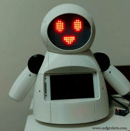
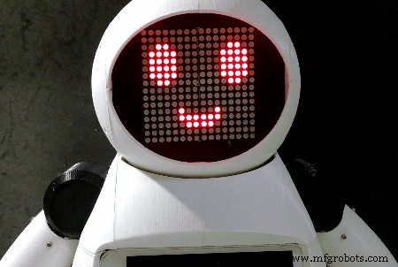
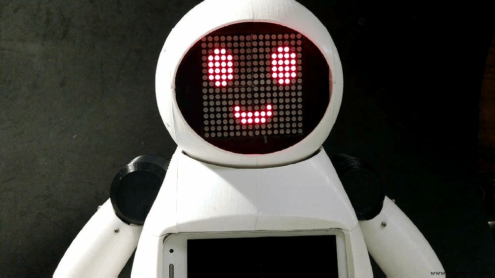
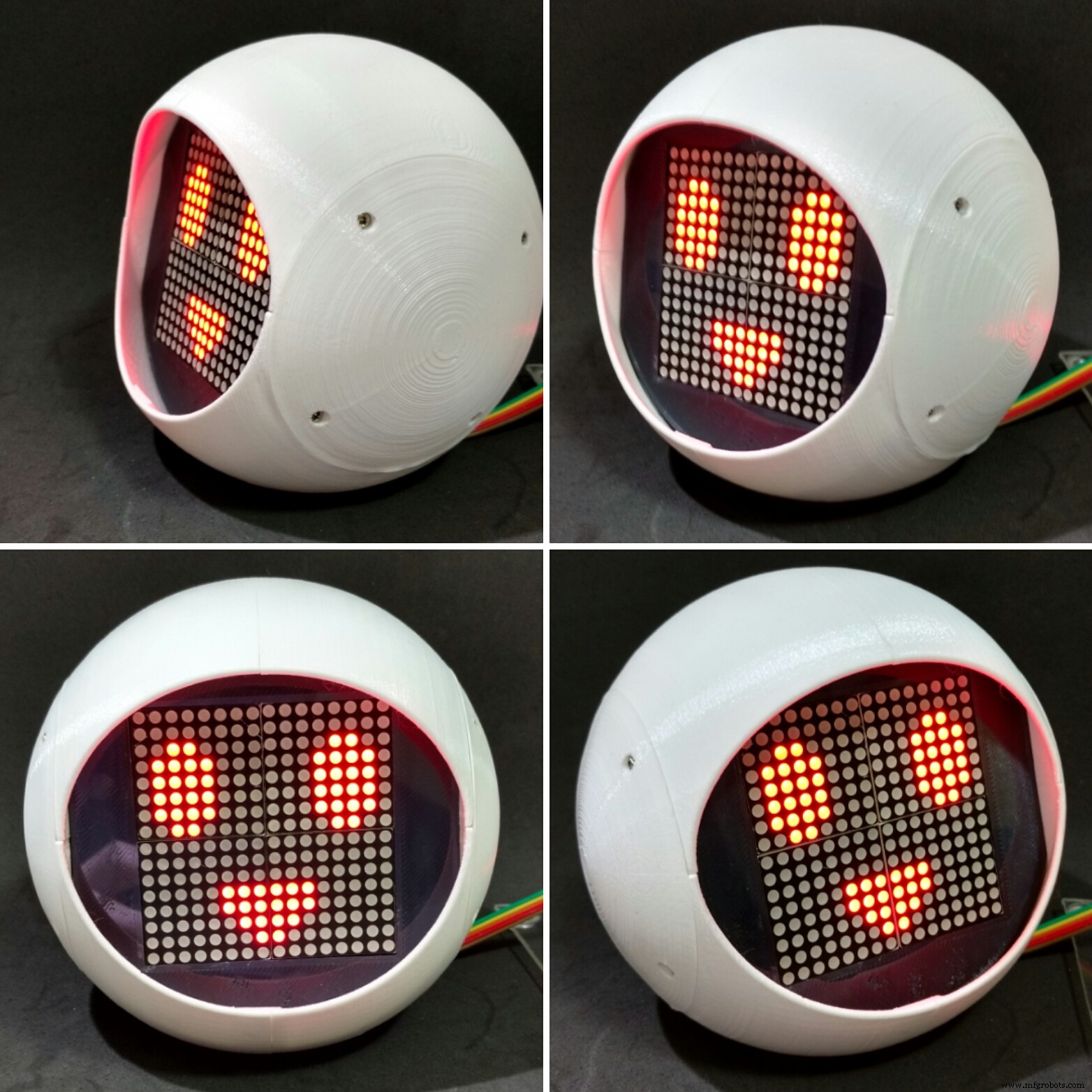
LEDアレイで構成された顔は、ロボットに感情を表現する能力を与えます。サーボモーター駆動のアームとネックは、小さなオートマトンにユーザーとの対話に必要な機動性を与えます。ロボットのコントロールセンターでは、Arduino UnoがESP8266モジュールとの通信を含め、すべての周辺機器とインターフェースを取ります。これにより、ユーザーは同じWi-Fiネットワークに接続された任意のデバイスを介して表情や動きを命令できます。
また、ロボットの胸にはスマートフォンが搭載されており、ロボットの操作者と子供たちの間で音声やビデオを送信するために使用されます。デバイス画面は、ロボット本体と対話するように設計されたゲームやその他のアプリケーションとの対話に引き続き使用できます。
ステップ2:ツールと材料
このプロジェクトでは、次のツールと資料が使用されました。
ツール:
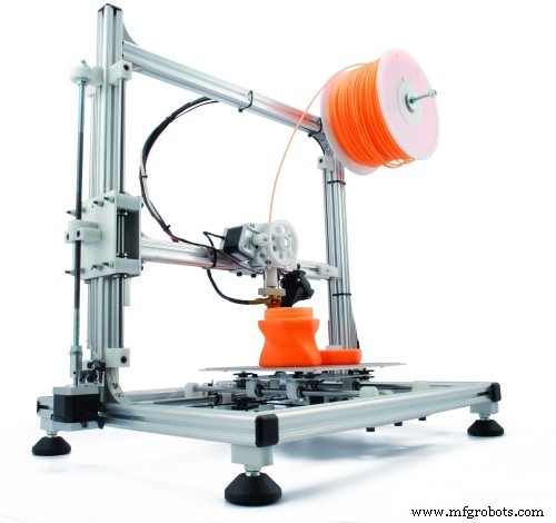
- 3Dプリンター -ロボットの全身が3Dプリントされています。構造全体を構築するには、数時間の3D印刷が必要でした。
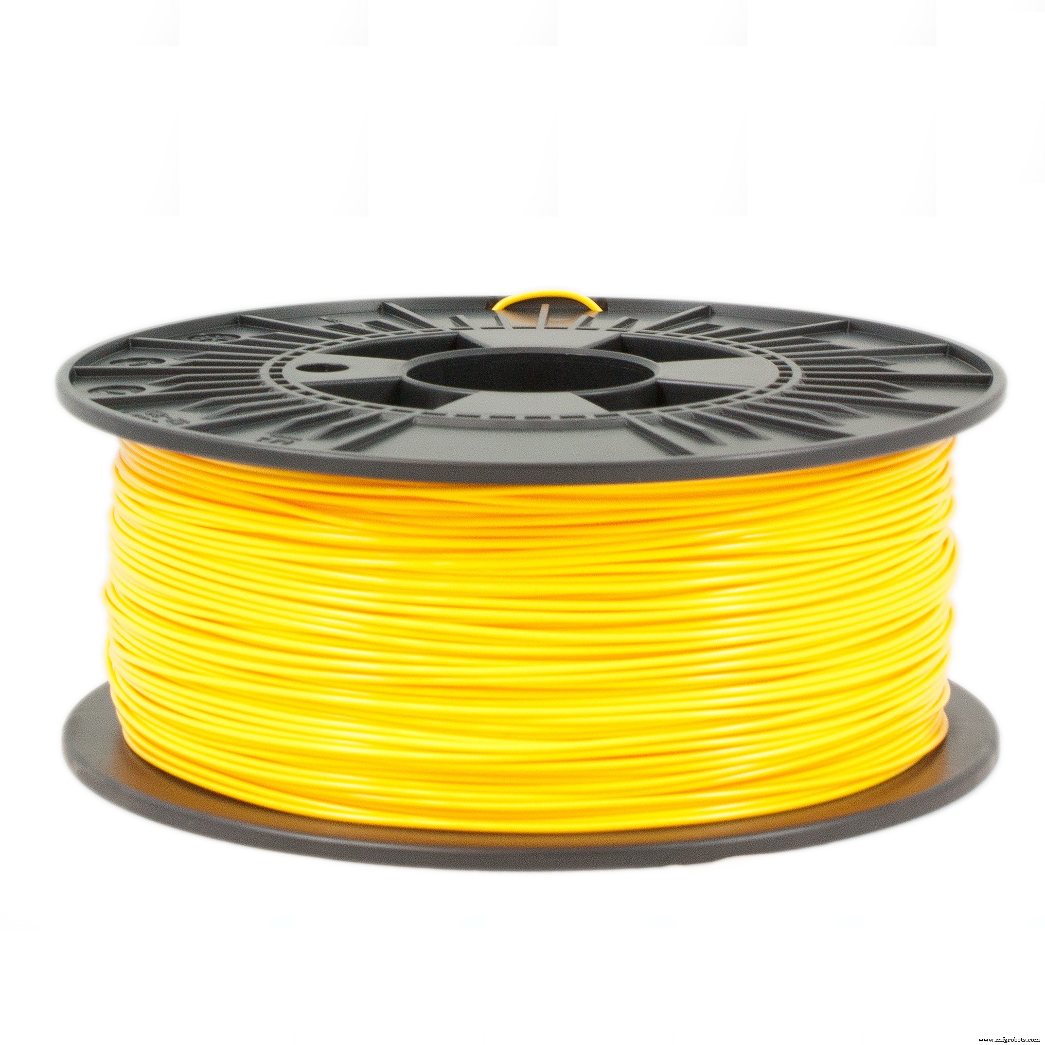
- PLAフィラメント -ボディの印刷に使用される白と黒のPLAフィラメント。
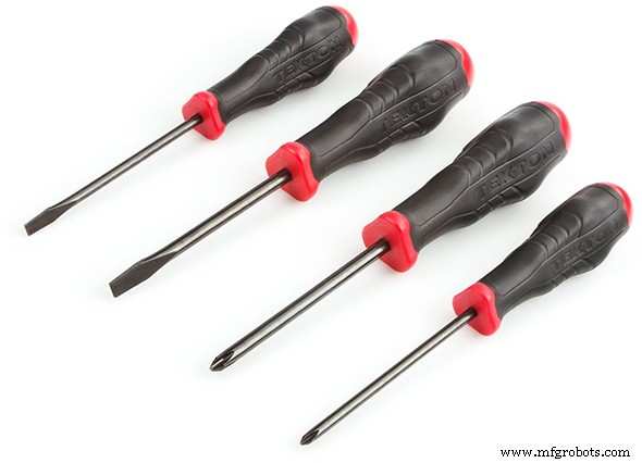
- スクリュードライバー -ほとんどの部品はボルトを使用して接続されています。
- 瞬間接着剤 -一部の部品は瞬間接着剤を使用して取り付けられました。
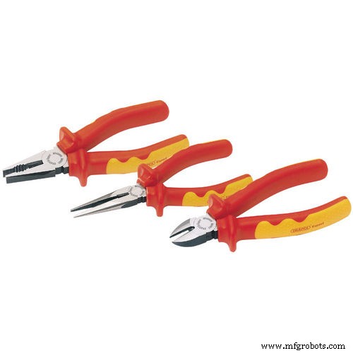
- ペンチとカッター
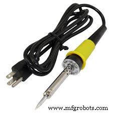
- はんだごてとワイヤー
エレクトロニクス :
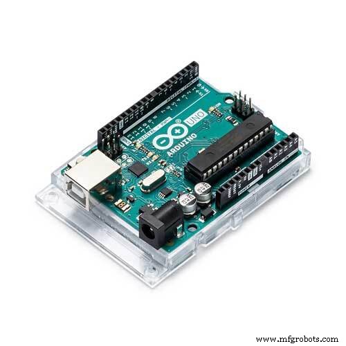
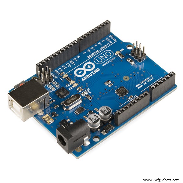
- Arduino Uno (リンク/リンク)-ロボットのメインコントローラーとして使用されます。モーターに信号を送信し、WiFiモジュールと通信します。
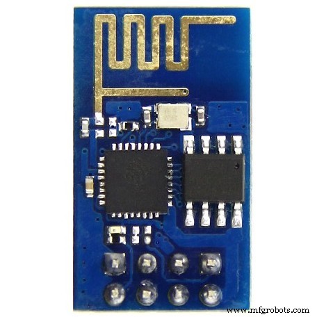
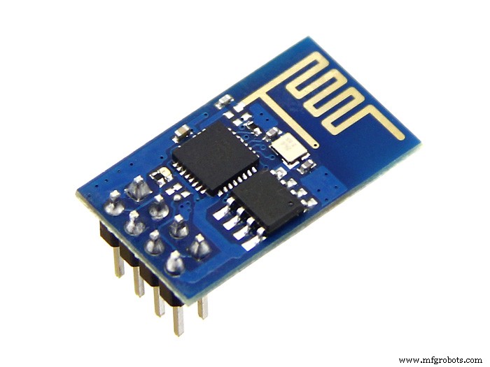
- ESP8266-01 (リンク/リンク)-「WiFiモデム」として使用されます。 ArduinoUnoによって実行される制御インターフェースから信号を受信します。
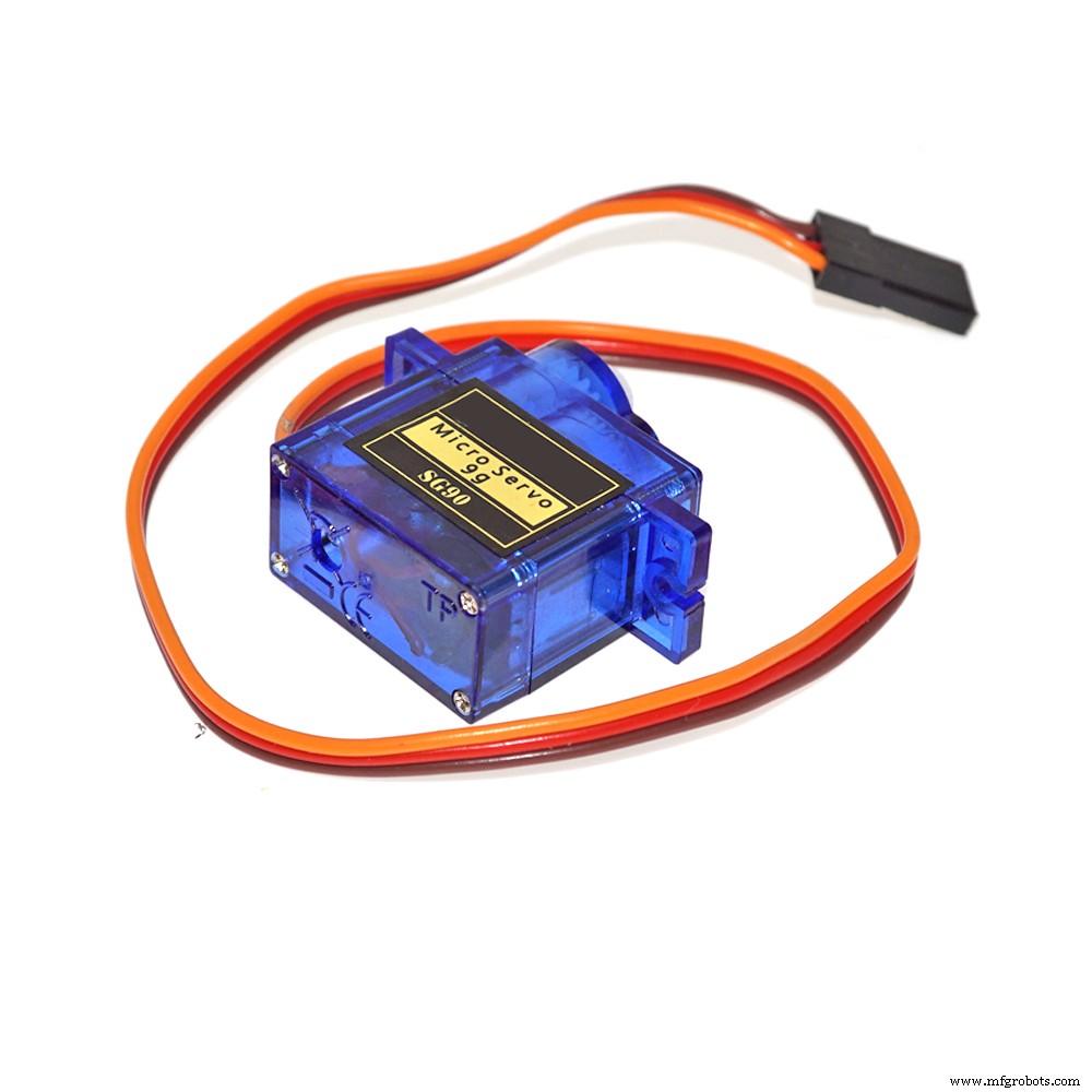
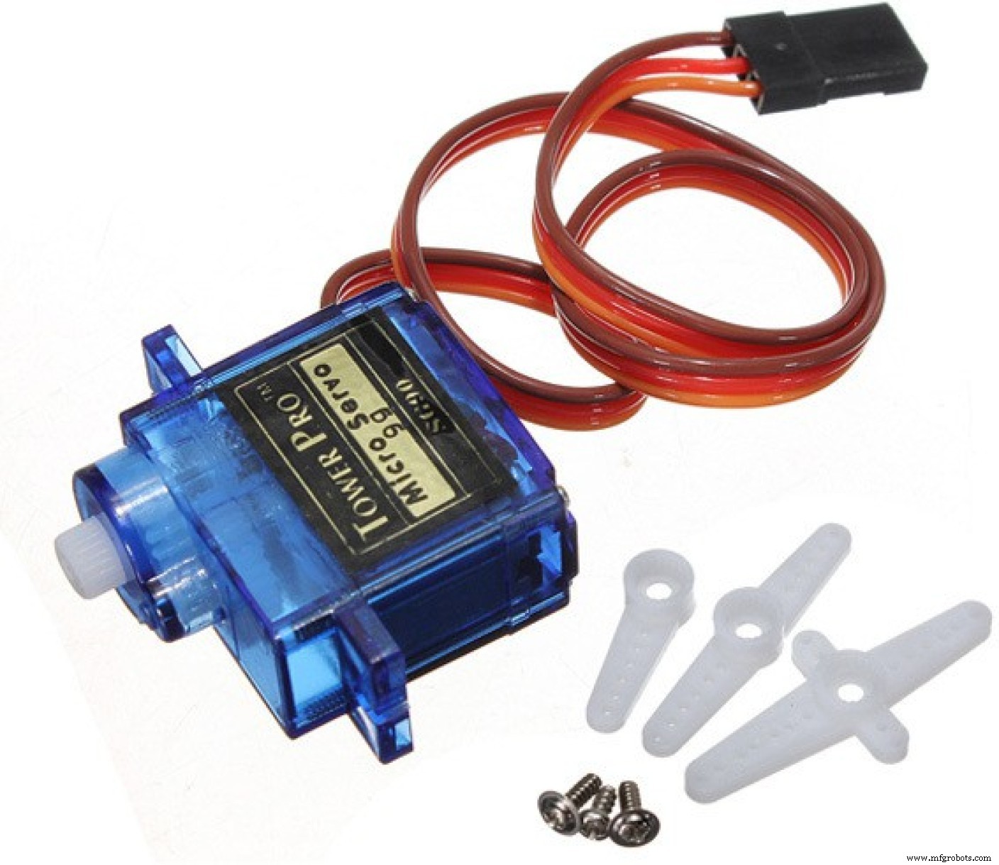
- SG90サーボモーター (x6)(リンク/リンク)-腕には4つのサーボが使用され、頭の動きには2つのサーボが使用されました。
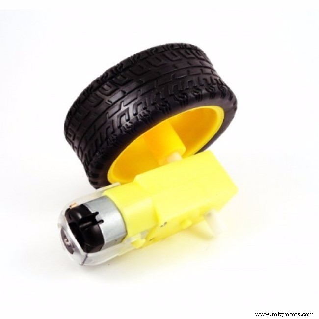
- 減速ホイールとゴム製ホイールを備えたDCモーター (x2)(リンク/リンク)-ロボットが短い距離を移動できるようにします。
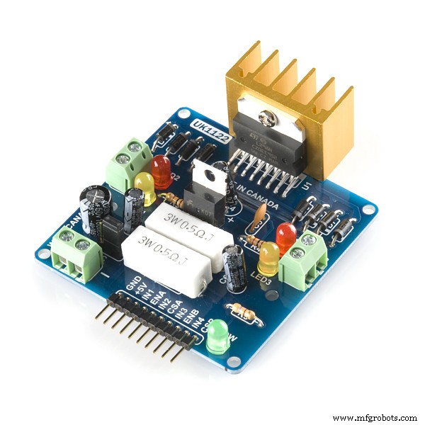
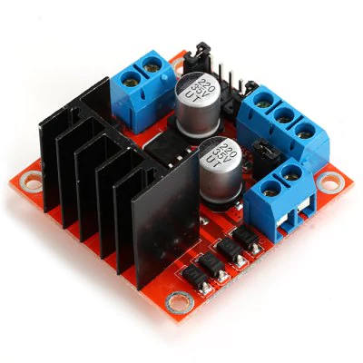
- L298NデュアルチャネルHブリッジ (x1)(リンク/リンク)-Arduinoデジタル出力をモーターへの電力電圧に変換します。
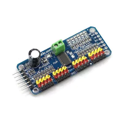
- 16チャンネルサーボコントローラー (リンク/リンク)-このボードを使用すると、2つのArduino出力のみを使用して複数のサーボモーターを制御できます。
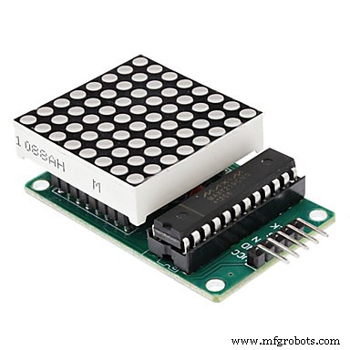
- MAX7219 8x8LEDディスプレイ (x4)(リンク/リンク)-ロボットの顔として使用されます。
- マイクロUSBケーブル -コードのアップロードに使用されます。
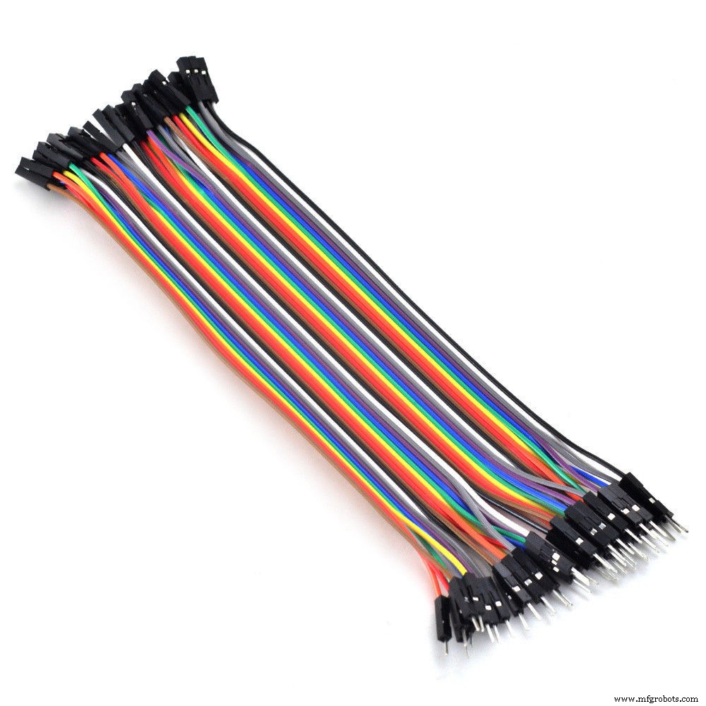
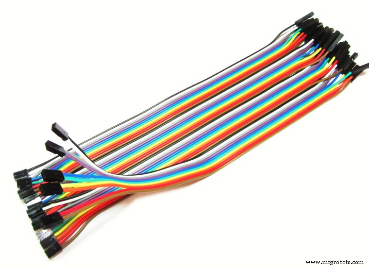
- メス-メスのジャンパー線 (いくつかの);
- オス-メスジャンパー線 (いくつかの);
- スマートフォン --Motorola 4.3 "MotoEスマートフォンが使用されました。同様のサイズの他のスマートフォンも同様に機能する可能性があります。
- 18650バッテリー (x2)(リンク)-Arduinoやその他の周辺機器に電力を供給するために使用されました。
- 18650バッテリーホルダー (x1)(リンク/リンク)-バッテリーを所定の位置に保持します。
- 1N4001ダイオード (x2)
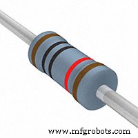
- 10kオームの抵抗器 (x3)
- 20mmオン/オフスイッチ (x1)
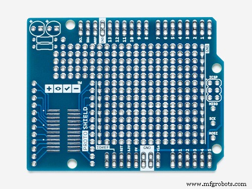
- プロトシールド (リンク)-回路の配線に役立ちます。
メカニズム:
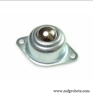
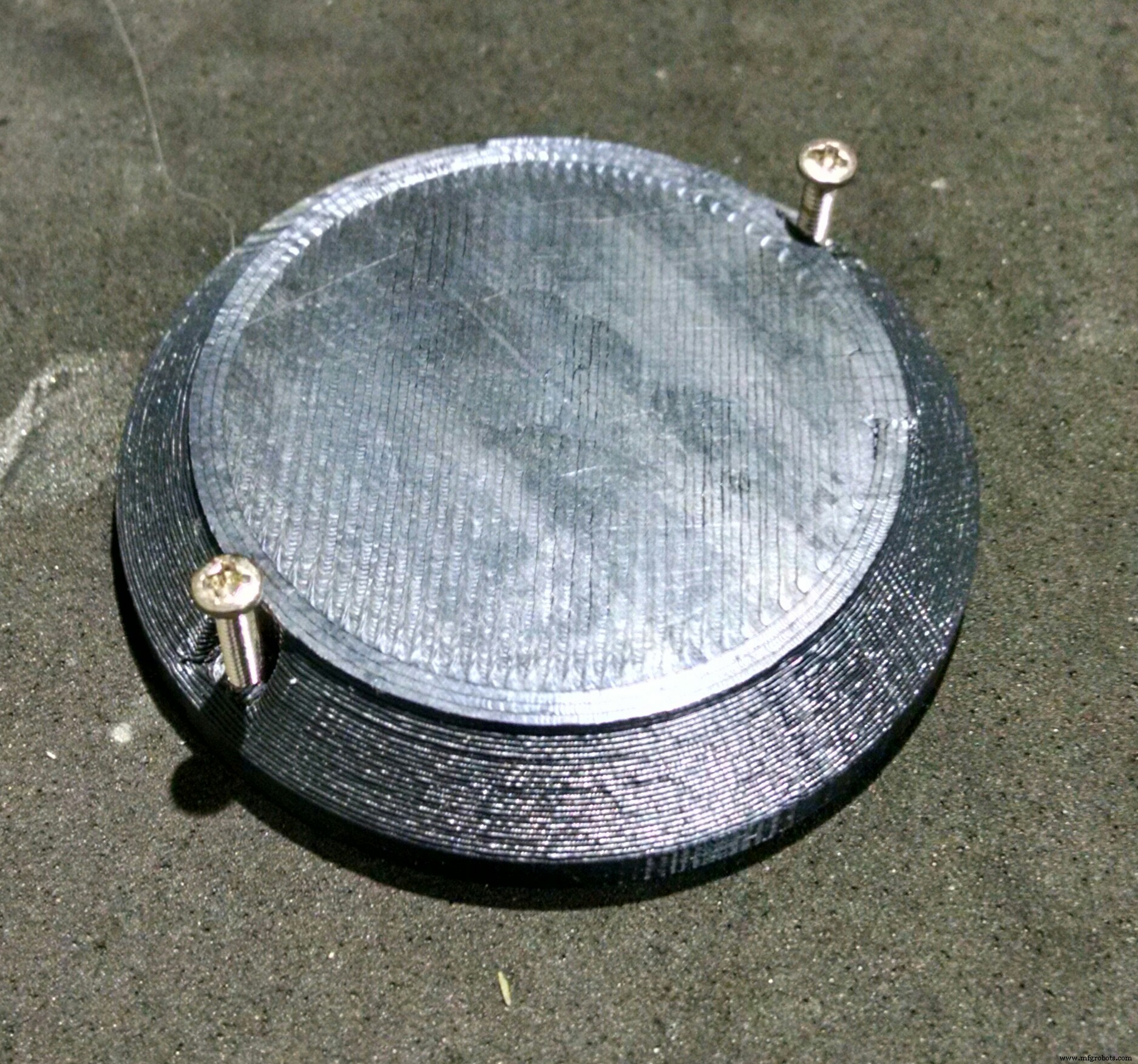
- ボールホイール (x2)
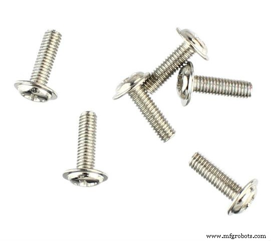
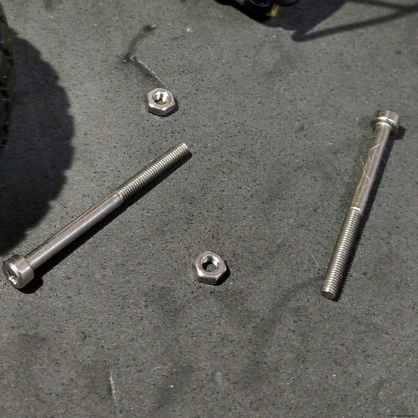
- M2x6.0mmボルト (+ -70)
- M2x10mmボルト (+ -20)
- M2x1.5mmナット (x10)
- M3x40mmボルト (x4)
- M3x1.5mmナット (x4)
上記のリンクは、このチュートリアルで使用されているアイテムを見つけて、このプロジェクトの開発をサポートできる場所を示しています。他の場所で自由に検索して、お気に入りのローカルストアまたはオンラインストアで購入してください。
Creality3D CR10miniをたった349.99ドルで購入できることをご存知ですか? Gearbestでクーポンコードcr10mini3dを使用して、入手してください:http://bit.ly/2FZ5OXw
ステップ3:3Dプリント

ロボット構造は、Autodesk Fusion 360を使用した3D印刷で完全に作成されました。プリンターの最大使用時間が重要なメーカースペースやファブラボでロボットのレプリカを作成できるようにするために、ロボットの設計は細かく分割されました。それぞれ3時間未満の印刷。パーツのセットは、本体に取り付けるために接着またはボルトで固定されています。
モデルは36の異なるパーツで構成されています。それらのほとんどは、サポートなしで、10%のインフィルで印刷されました。
- ヘッドトップ(右/左)
- 頭の下部(右/左)
- ヘッドサイドキャップ(右/左)
- フェイスバックプレート
- フェイスフロントプレート
- 首軸1
- ネック軸2
- 首軸3
- ネックセンター
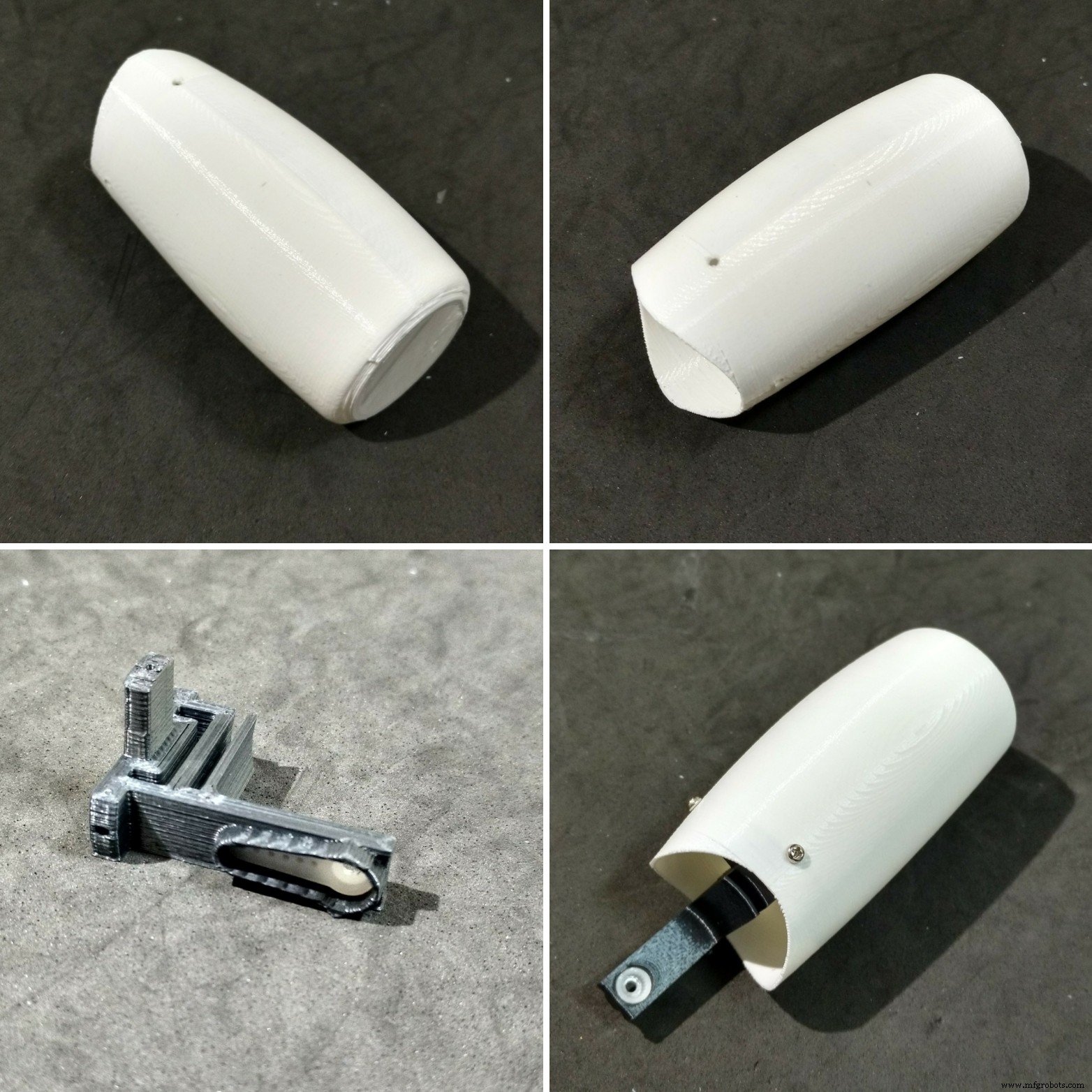
- 腕(右/左)
- 肩(右/左)
- ショルダーカップ(右/左)
- ショルダーキャップ(右/左)
- アーム軸(右/左)
- バスト(右/左)
- 胸(右/左/正面)
- ホイール(右/左)
- ベース
- 電話ホルダー
- 戻る(右/左)
- ノブ(右/左)
- ロッカー(右/左)
ロボットの取り付け手順は、次の手順で説明されています。
次のWebサイトですべてのstlファイルをダウンロードできます。
- https://www.thingiverse.com/thing:2765192
- https://pinshape.com/items/42221-3d-printed-joy-robot-robo-da-alegria
- https://www.youmagine.com/designs/joy-robot-robo-da-alegria
- https://cults3d.com/en/3d-model/gadget/joy-robot-robo-da-alegria
これは実験的なプロトタイプです。一部のパーツには、いくつかの改善が必要です(プロジェクトを後で更新するため)。いくつかの既知の問題があります:
- 一部のサーボの配線とショルダーの干渉。
- 頭と胸像の間の摩擦。
- 車輪と構造物の間の摩擦。
- 一部のネジの穴がきつすぎるため、ドリルビットまたはホビーナイフで拡大する必要があります。
3Dプリンターをお持ちでない場合は、次のことができます。
- 友人に印刷してもらいます。
- 近くのハッカー/メーカースペースを見つけます。モデルはいくつかの部分に分割されているため、各部分を個別に印刷するのに4時間もかかりません。一部のハッカー/メーカースペースでは、使用した材料に対してのみ課金されます。
- 独自の3Dプリンターを購入します。 AnetA8はたったの$ 165.99で見つけることができます。 Gearbestで入手してください:http://bit.ly/2kqVOdO
- DIYキットの購入に興味がありますか?十分な数の人が興味を持っているなら、Tindie.comでDIYキットを提供しているかもしれません。ご希望の場合は、メッセージを送ってください。
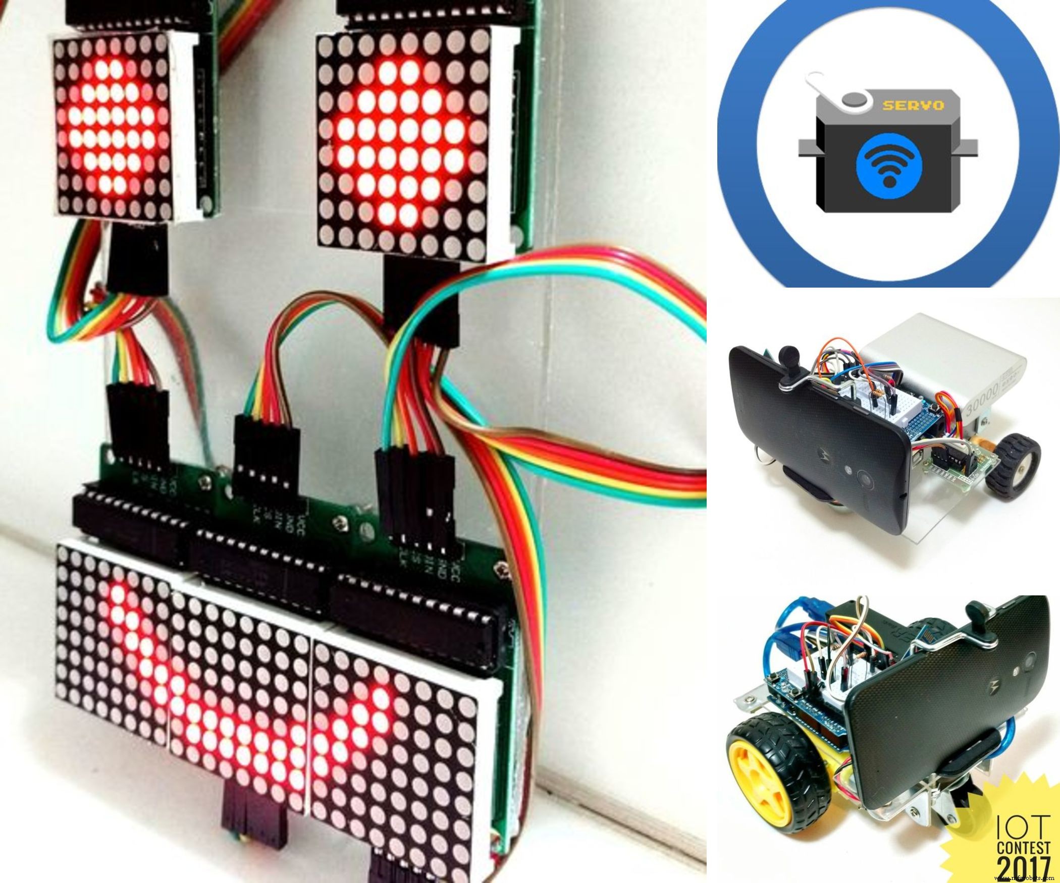
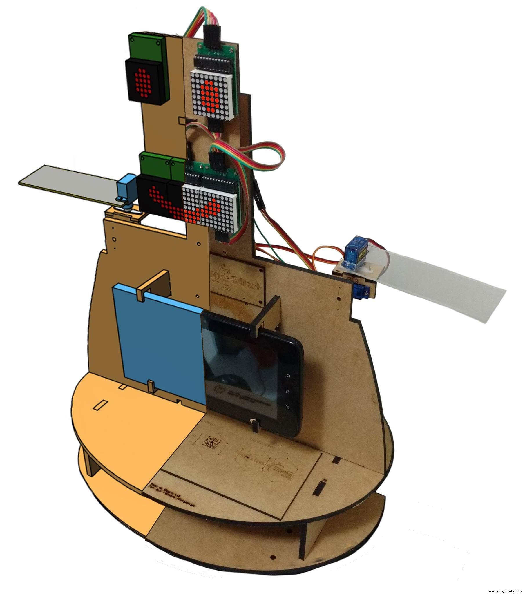
ステップ4:回路の概要
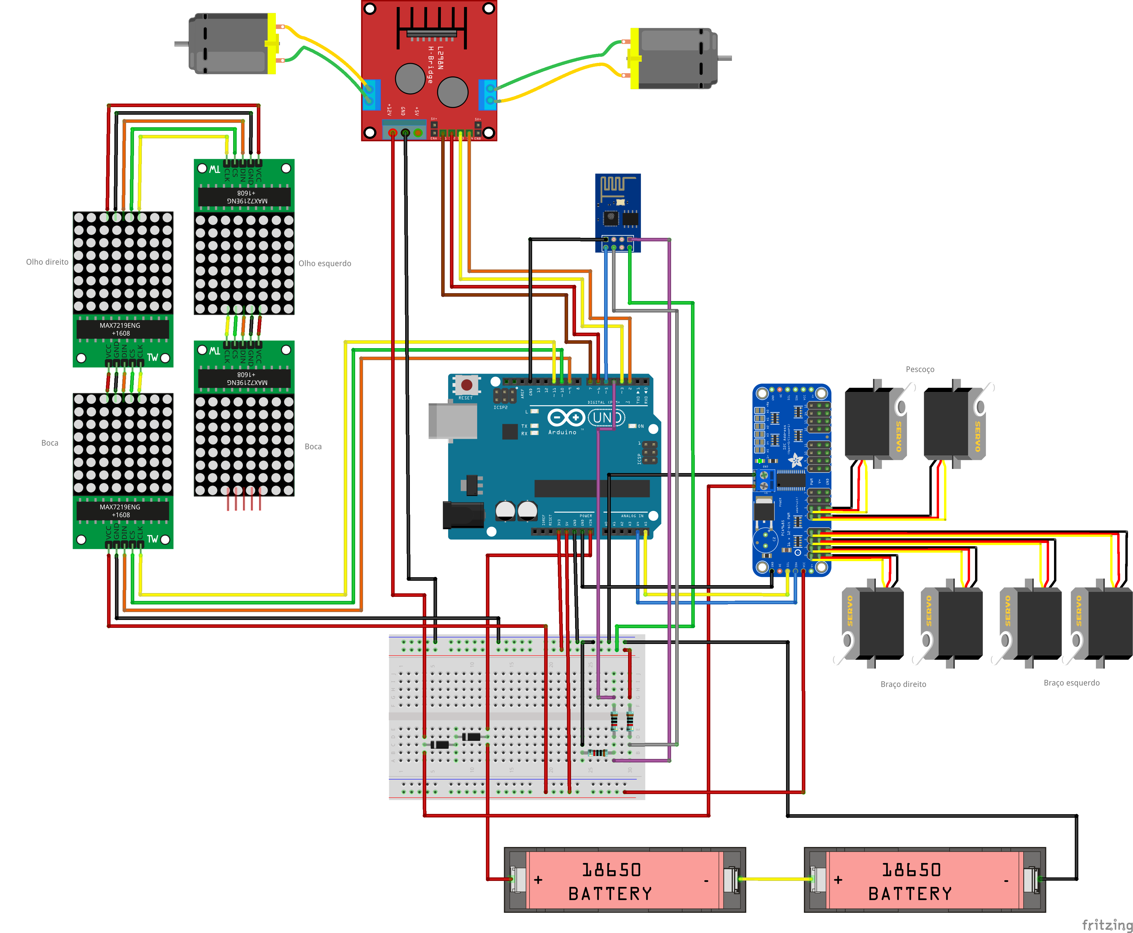
ロボットは、ArduinoUnoをコアとして使用して制御されます。 Arduinoは、Wi-Fiネットワークを介してロボットをリモートコントロールするために使用されるESP8266-01モジュールとインターフェースします。
16チャンネルのサーボコントローラーはI2C通信を使用してArduinoに接続され、6つのサーボモーター(ネック用に2つ、各アーム用に2つ)を制御します。 5つの8x8LEDマトリックスのアレイは、Arduinoによって電力供給および制御されます。 4つのArduinoのデジタル出力は、hブリッジを使用して2つのDCモーターを制御するために使用されます。
回路は2つのUSBパワーバンクを使用して電力を供給されます。1つはモーター用、もう1つはArduino用です。サインルパワーパックを使用してロボット全体に電力を供給しようとしました。しかし、ESP8266は、DCモーターのオン/オフ時にスパイクが原因で接続が失われていました。
ロボットの胸にはスマートフォンが付いています。これは、通常のコンピューターでホストされているコントロールインターフェイスとの間でビデオとオーディオをブロードキャストするために使用されます。また、ESP6288にコマンドを送信して、ロボット自体の本体を制御することもできます。
ここで使用されているコンポーネントは、その目的に合わせて最適化されていない可能性があることに気付くかもしれません。たとえば、Arduino + ESP8266の組み合わせの代わりにNodeMCUを使用できます。カメラ付きのRapsberryPiはスマートフォンに取って代わり、モーターも制御します。 Androidスマートフォンをロボットの「頭脳」として使用することも可能です。それは本当です... Arduino Unoが選ばれたのは、それが非常にアクセスしやすく、誰にとっても使いやすいからです。このプロジェクトを開始するまでに、ESPとRaspberry Piボードは、私たちが住んでいる場所ではまだ比較的高価です...かつては安価なロボットを構築したかったので、Arduinoボードはその時点で最高の選択肢です。
robot%2Bmk0%2B-%2Brev8_Esquem_C3_A1tico.pdf robot%2Bmk0%2B-%2Brev8_bb.pdf
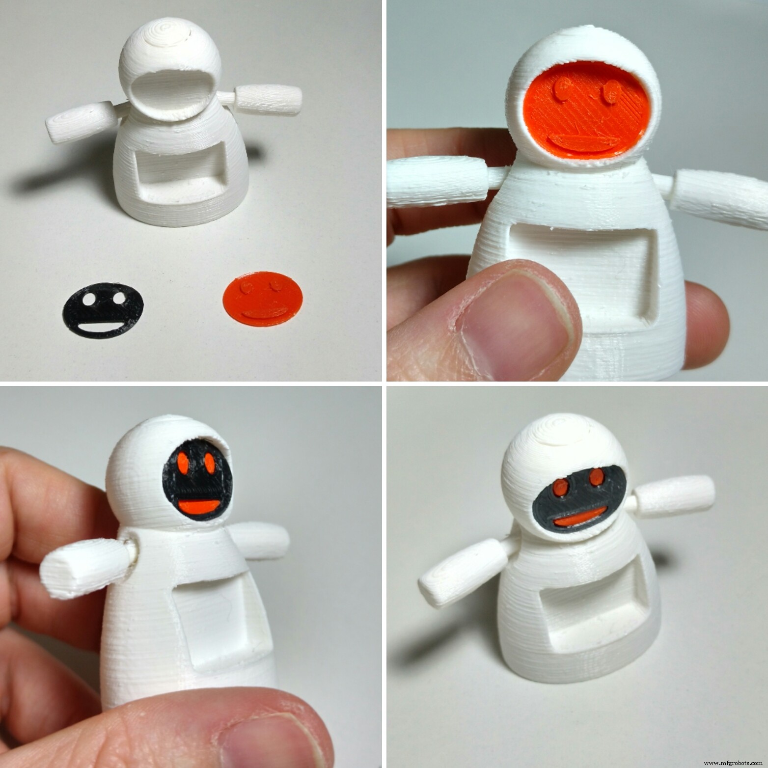
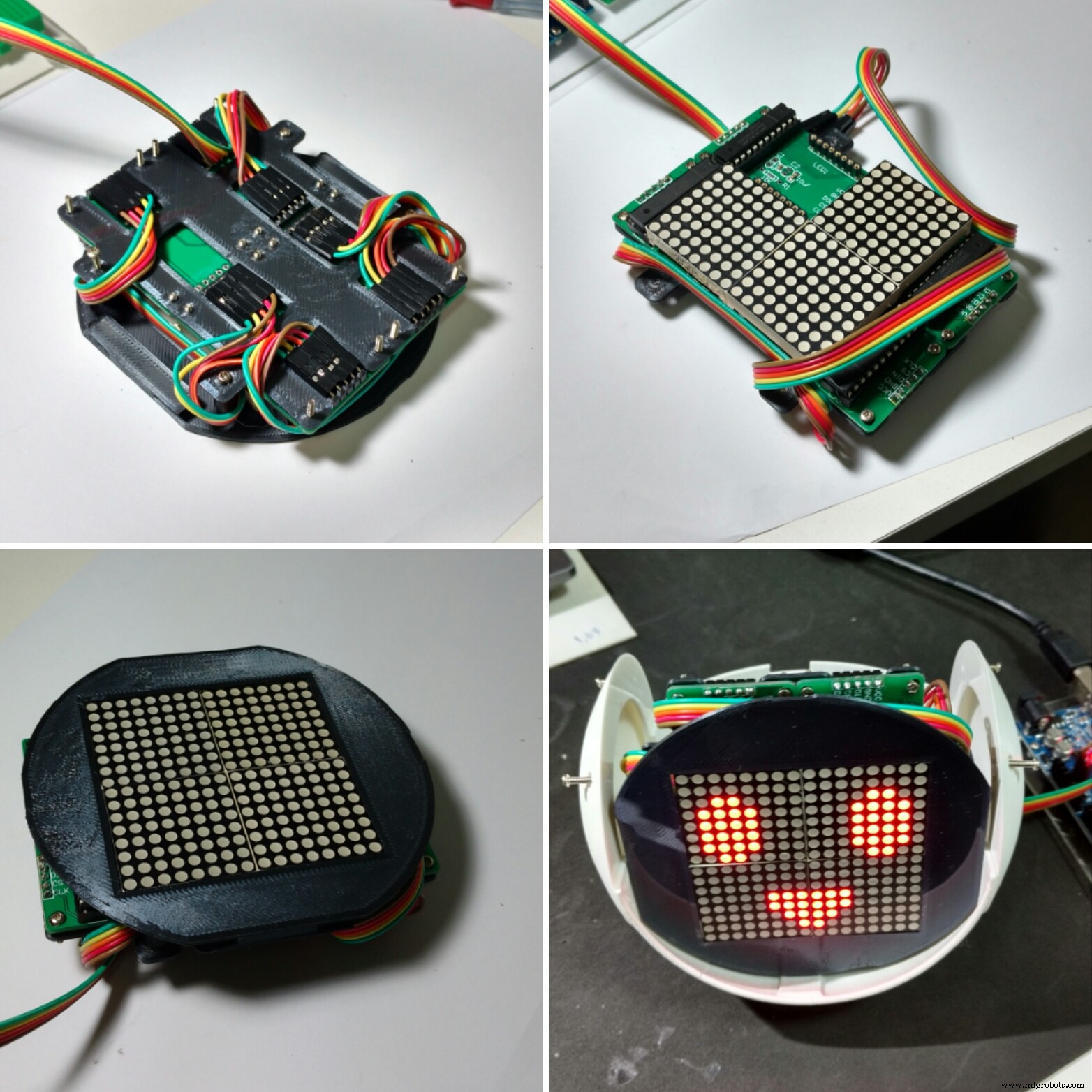
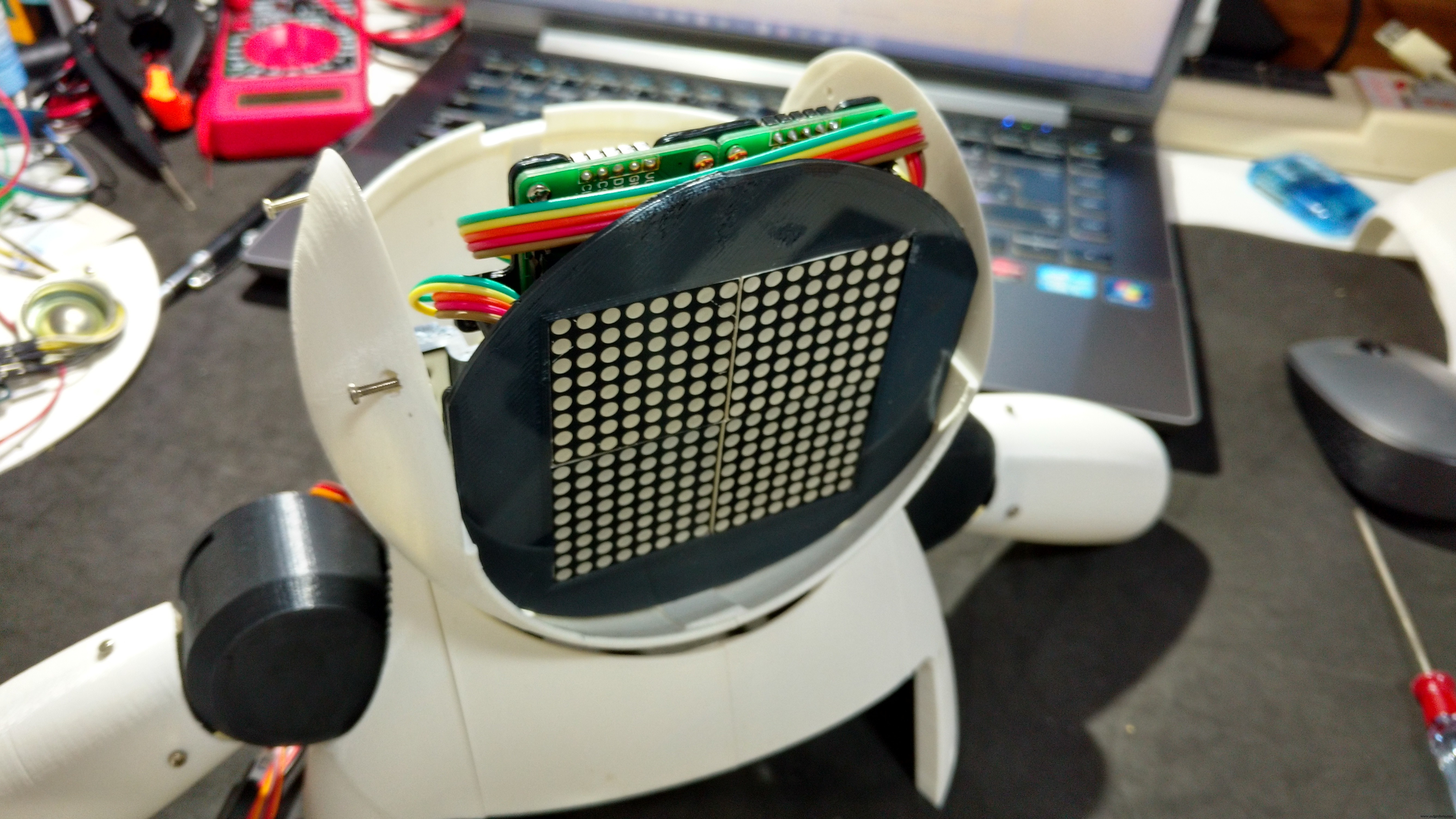
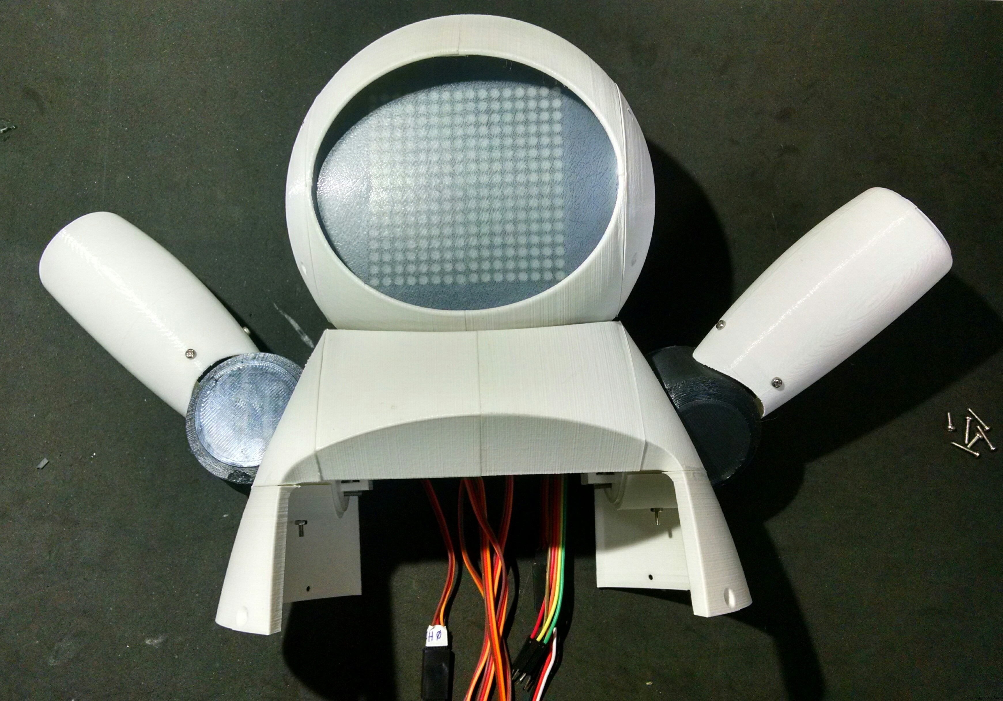
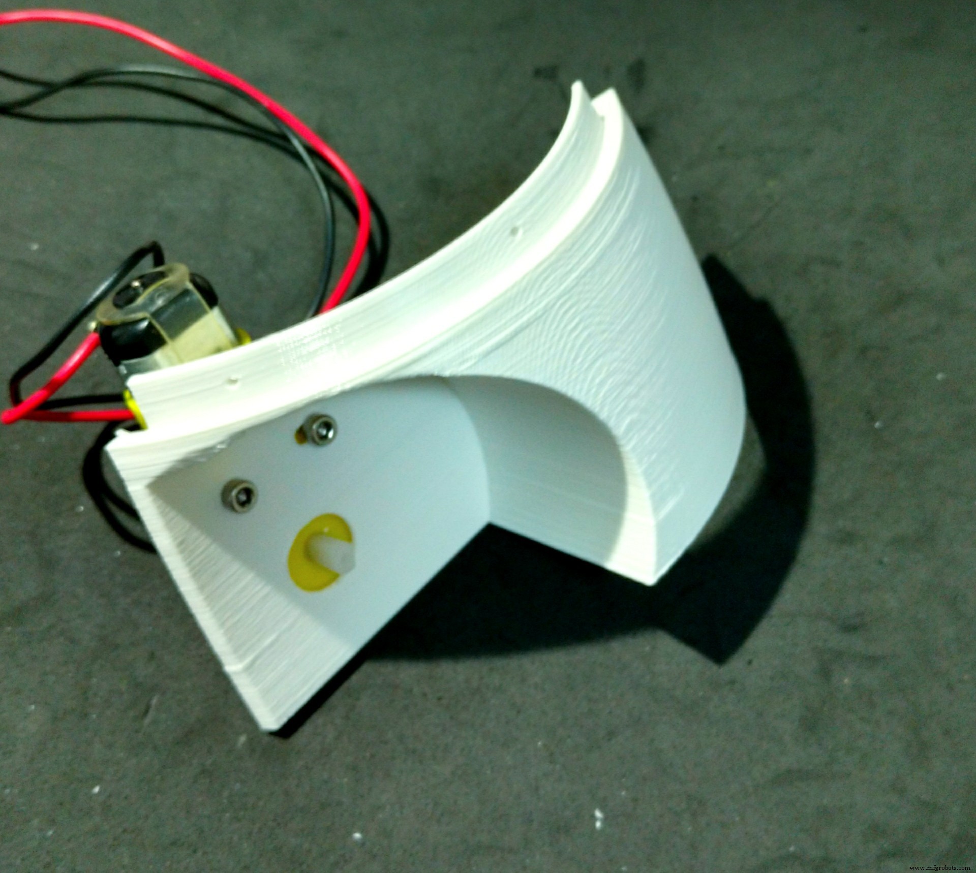
ステップ5:顔を組み立てる
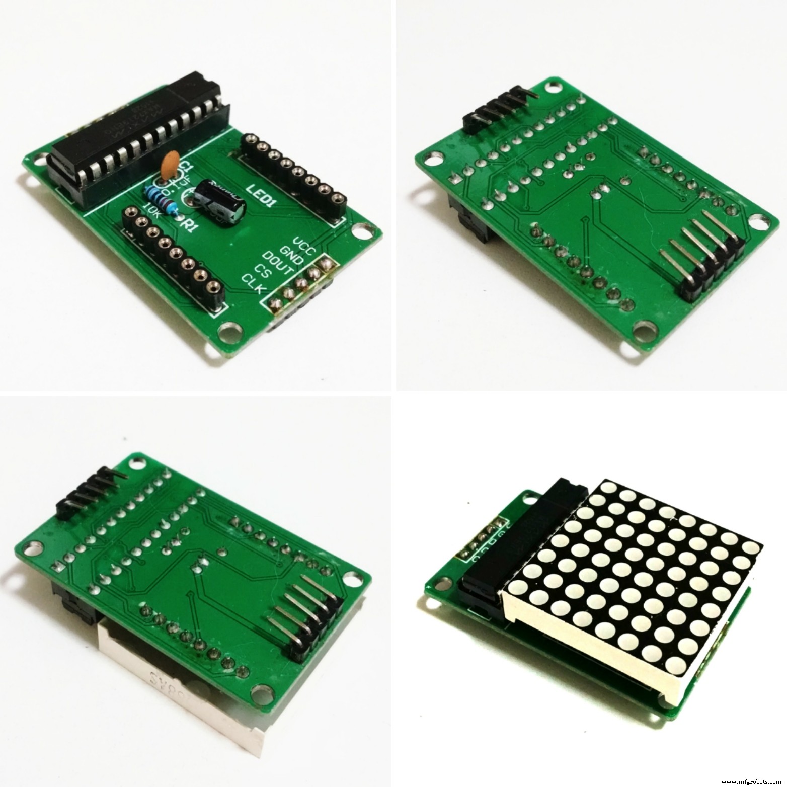

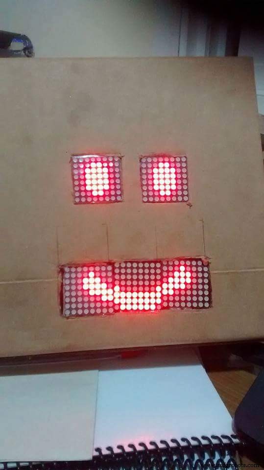
ロボットの顔には4つの8x8LEDマトリックスが使用されました。
構造は2つの部分(フェースバックプレートとフェースフロントプレート)に分割され、黒のPLAを使用して3Dプリントされました。 10%のインフィルとサポートなしで、3Dプリントに約2.5時間かかりました。
スペースの制限により、LEDマトリックスのコネクタをはんだ除去し、以下に説明するように位置を変更する必要がありました。
- LEDマトリックスを取り外します。
- デソルダー入力および出力コネクタ。
- 回路基板の反対側よりもはんだ付けし直し、ピンが基板の中心を指すようにします。
最終結果は画像で確認できます。
次に、16個のM2x6mmボルトを使用して、4つのLEDマトリックスをバックプレートに取り付けました。ピンは回路図に従って接続されました。
最初のマトリックスは、5線式のオス-メスジャンパーを使用して接続されました。オス側は後でArduinoピンに接続されました。メス側はマトリックス入力ピンに接続されています。各マトリックスの出力は、メス-メスジャンパーを使用して次のマトリックスの入力に接続されます。
マトリックスを接続した後、4本のM2ボルトを使用してフロントプレートを取り付けます。ジャンパーを前後のパネルに巻き付けて、ワイヤーが緩まないようにします。
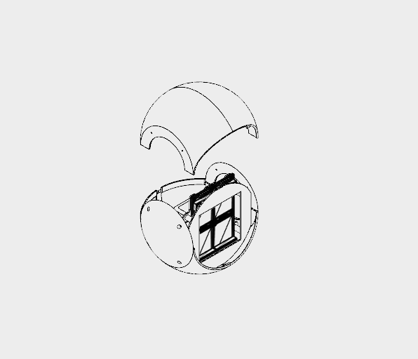
フェイスモジュールは、次の手順で説明するように、後でロボットの頭の中に取り付けられます。
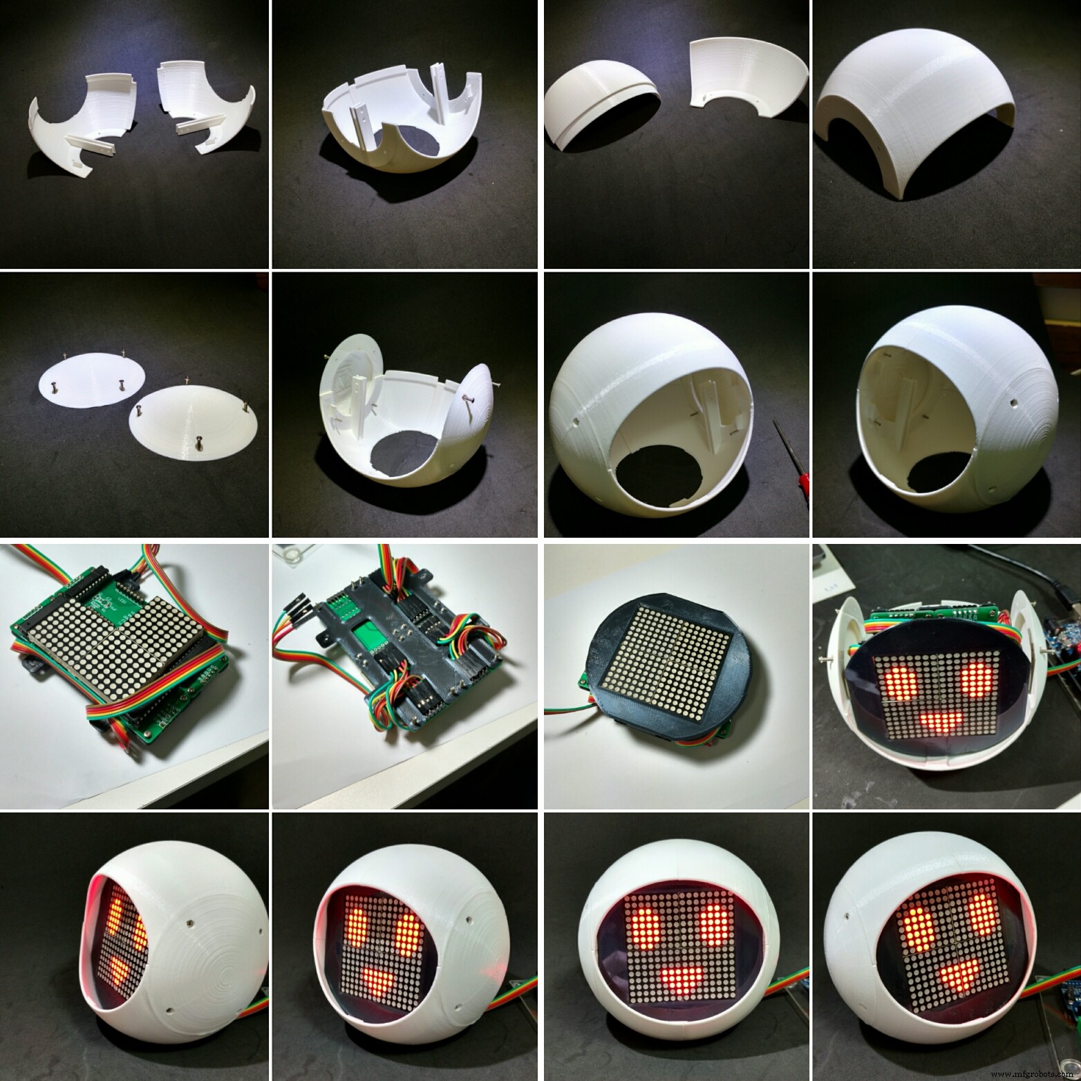
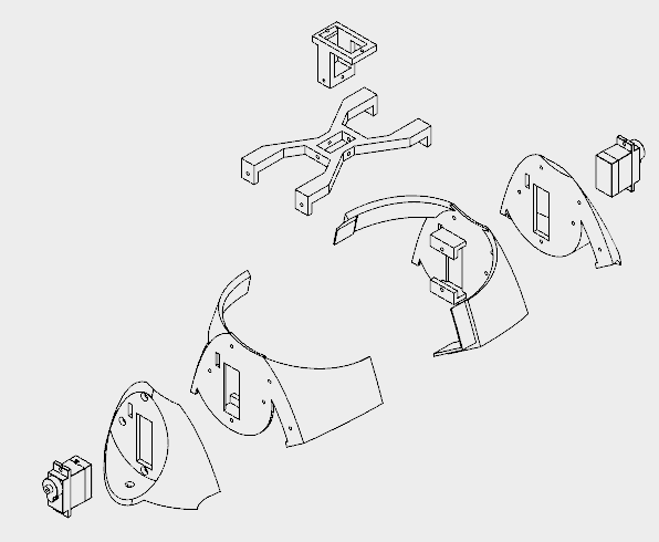
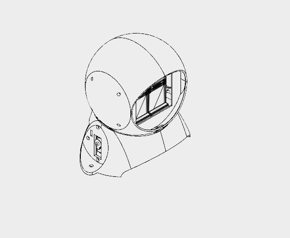
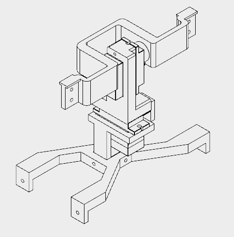
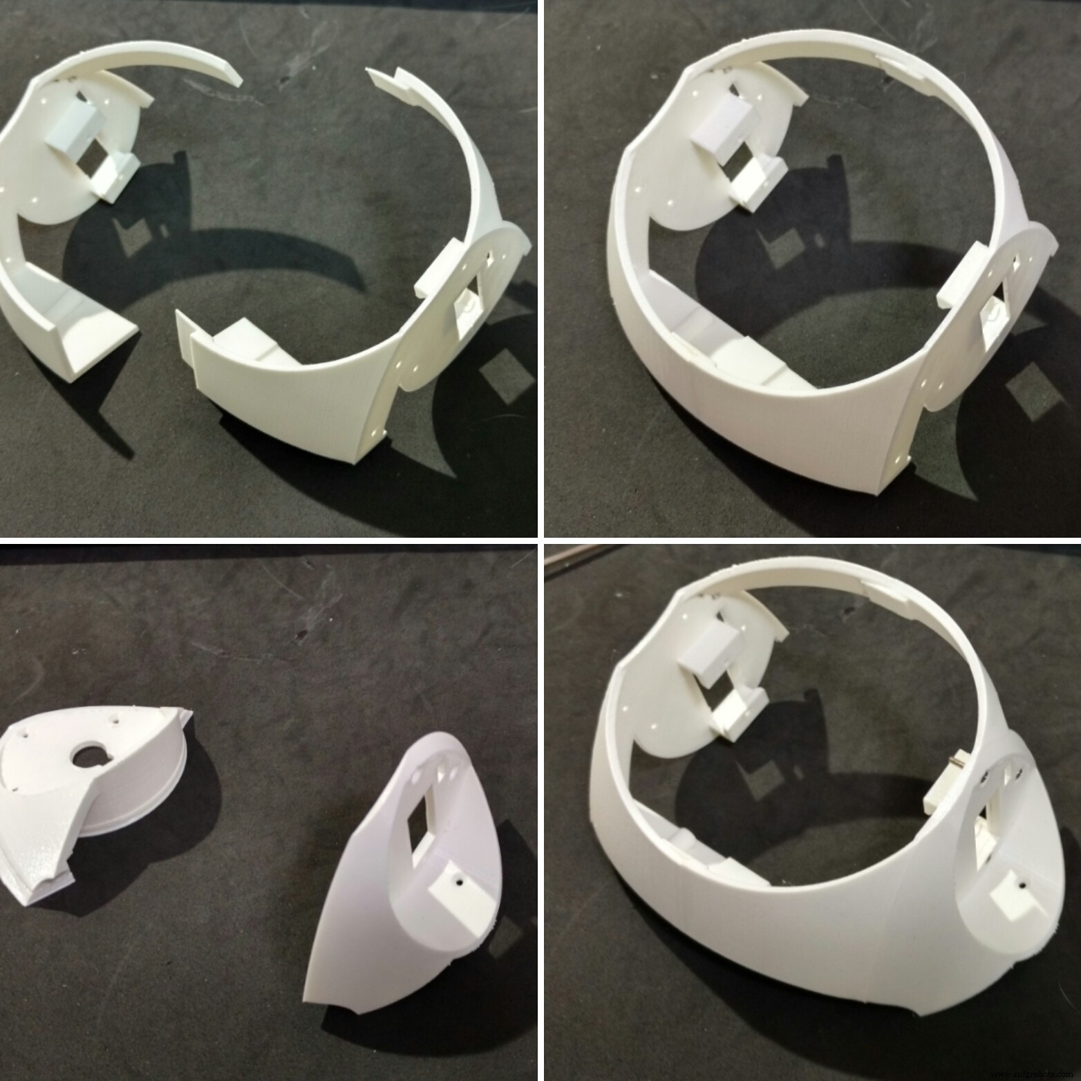
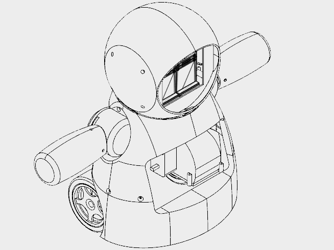
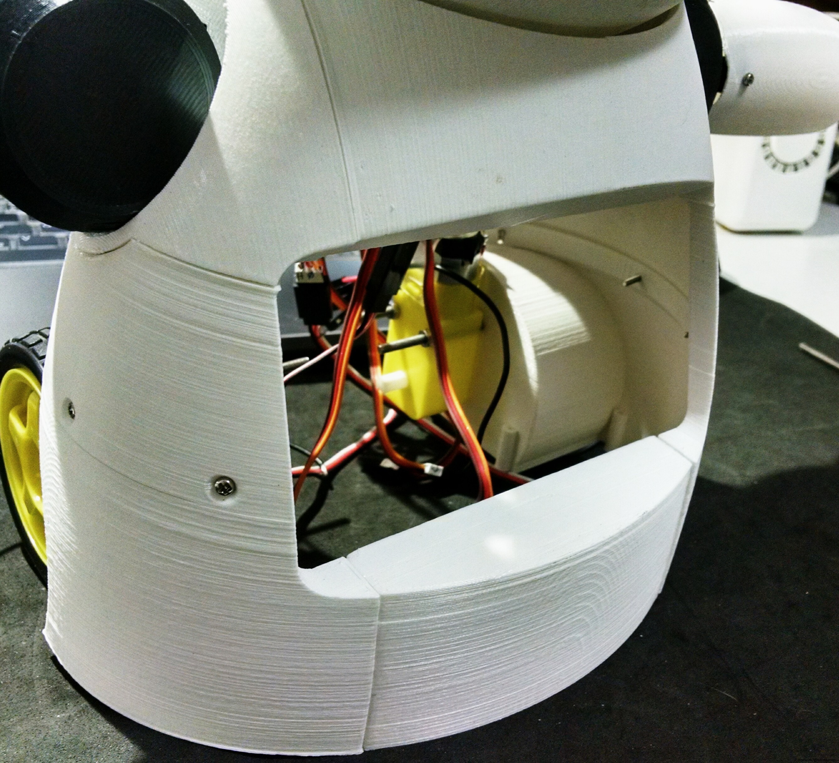
ステップ6:ヘッドの取り付け
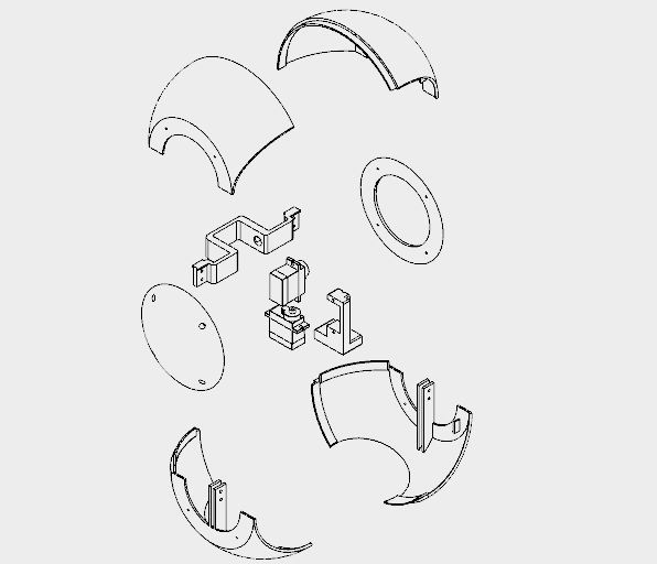
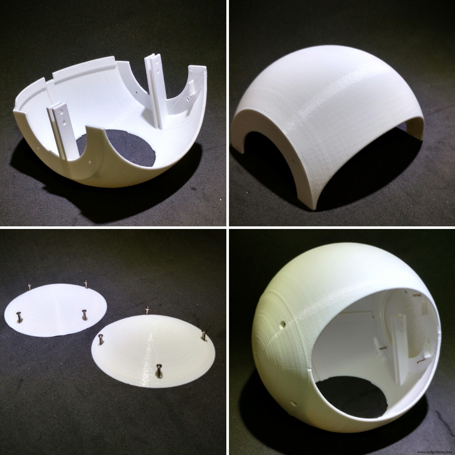
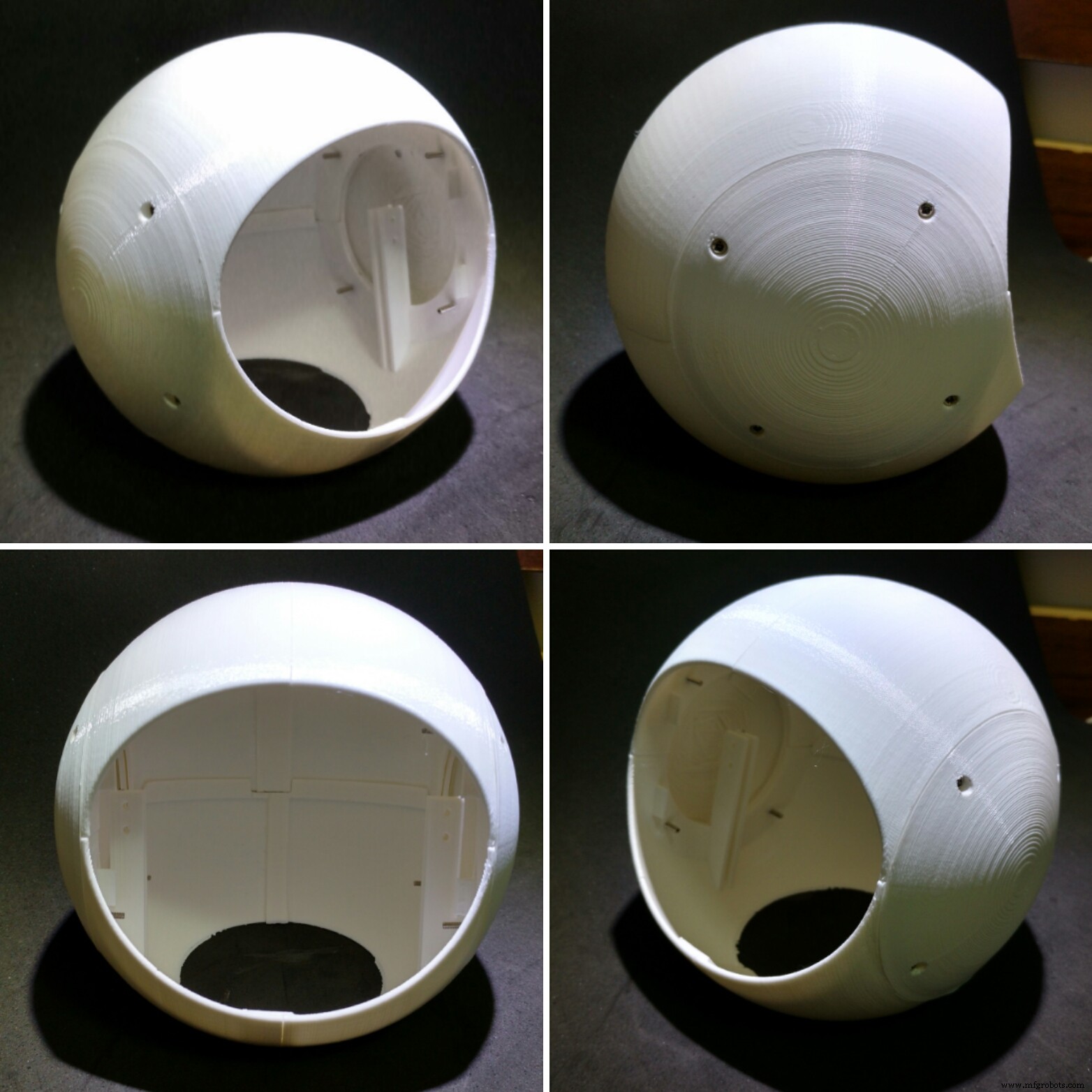

ロボットのヘッドは8番目の3D印刷パーツに分割され、すべてが0.2mmの解像度、10%のインフィル、サポートなしの白いPLAで印刷されました。
- ヘッドトップ(右と左)
- 頭の下部(右と左)
- ヘッドキャップ(右と左)
- 首軸1
- ネック軸2
直径130mmの構造物を印刷するのに約18時間かかりました。
頭の上部と下部は2つの部分に分かれています。それらは瞬間接着剤を使用して一緒に接着されています。接着剤を塗り、数時間休ませます。
サイドキャップは、頭の上下の側面に取り付けられたボルトを使用して取り付けられます。このように、ヘッド上部に取り付けられているネジを外すことで、ヘッドを取り外して修理することができます。ヘッドを閉じる前に、ロボットの顔(前の手順で説明)とバスト(次の手順で説明)を組み立てます。
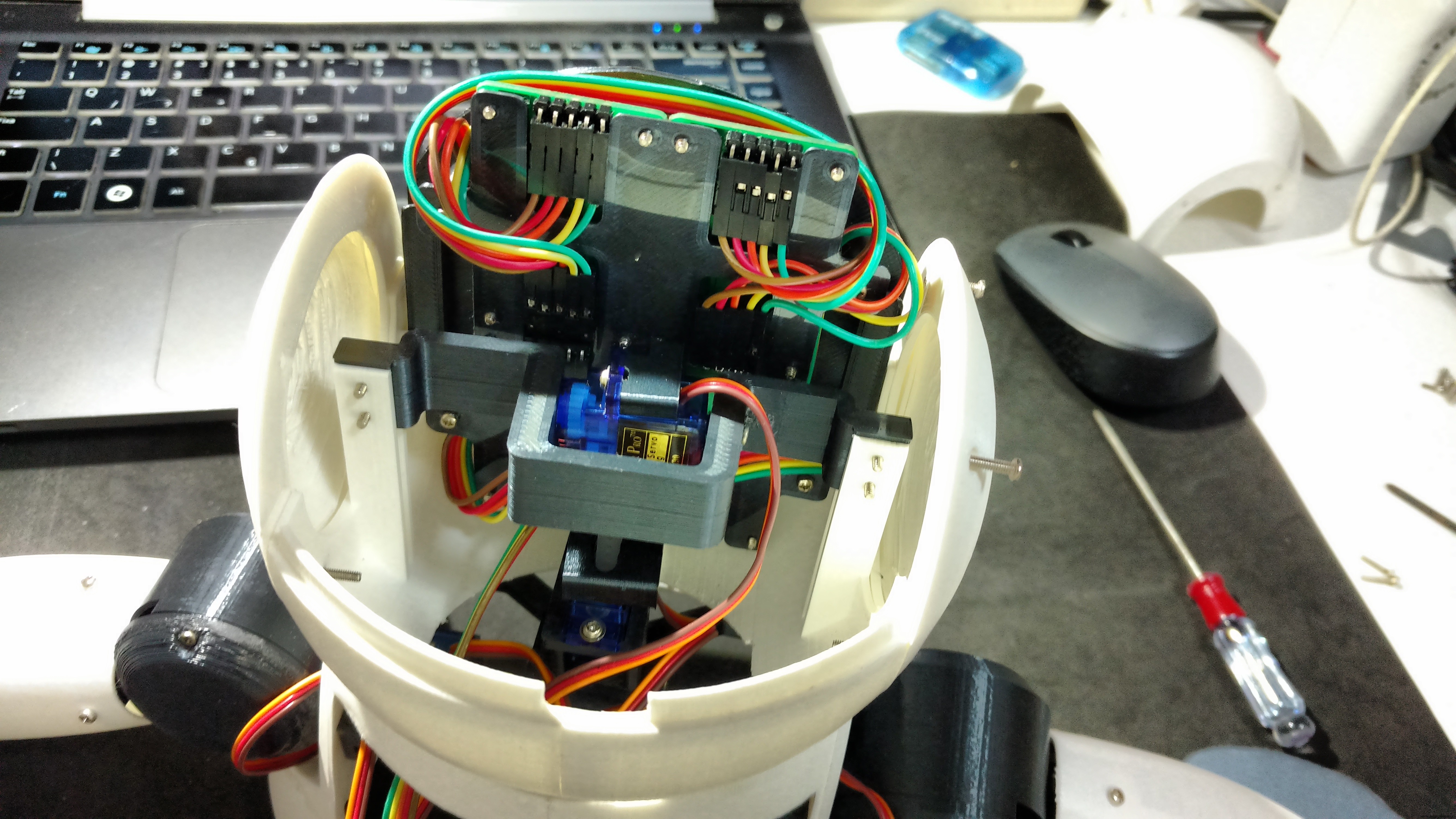
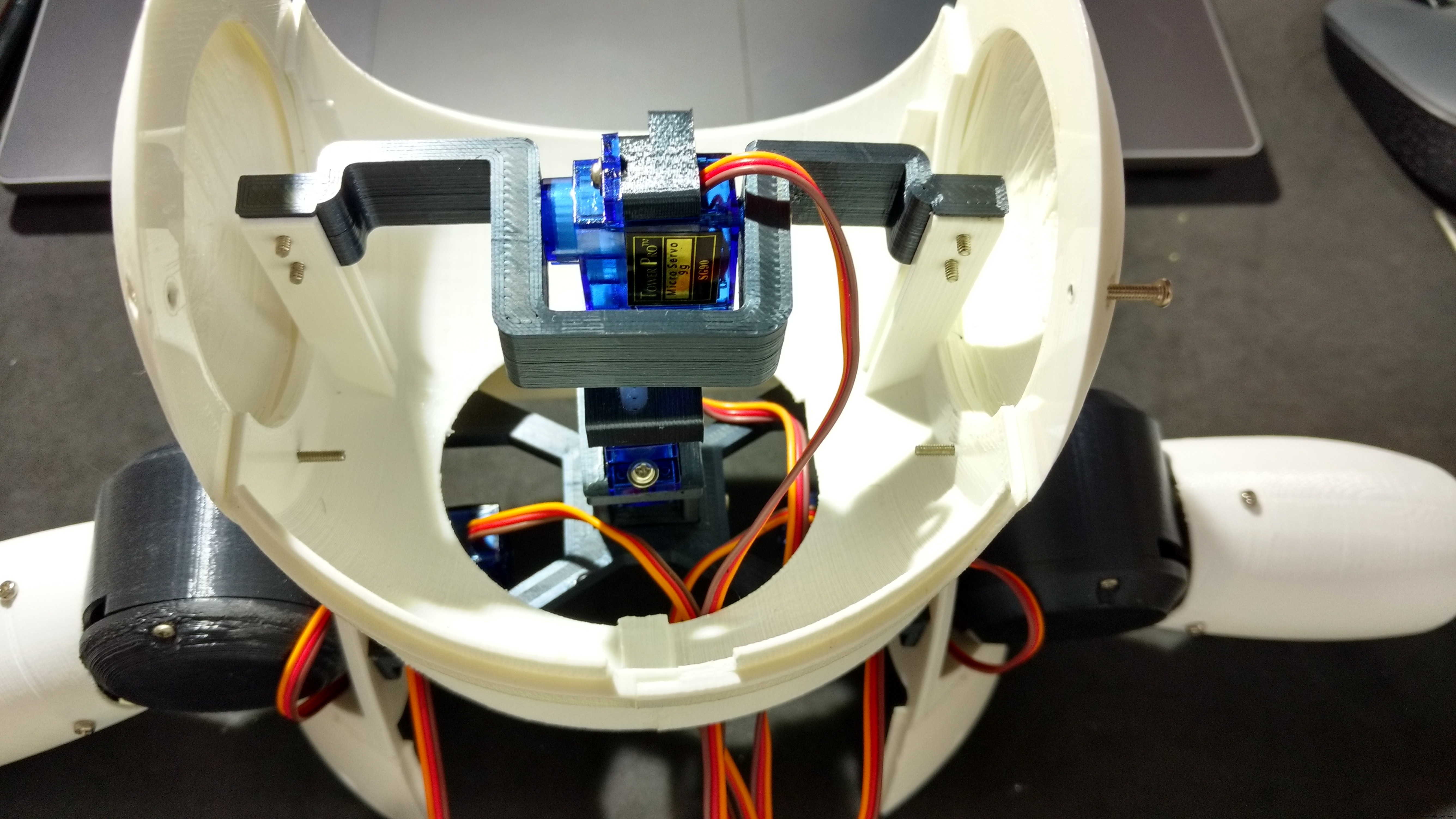
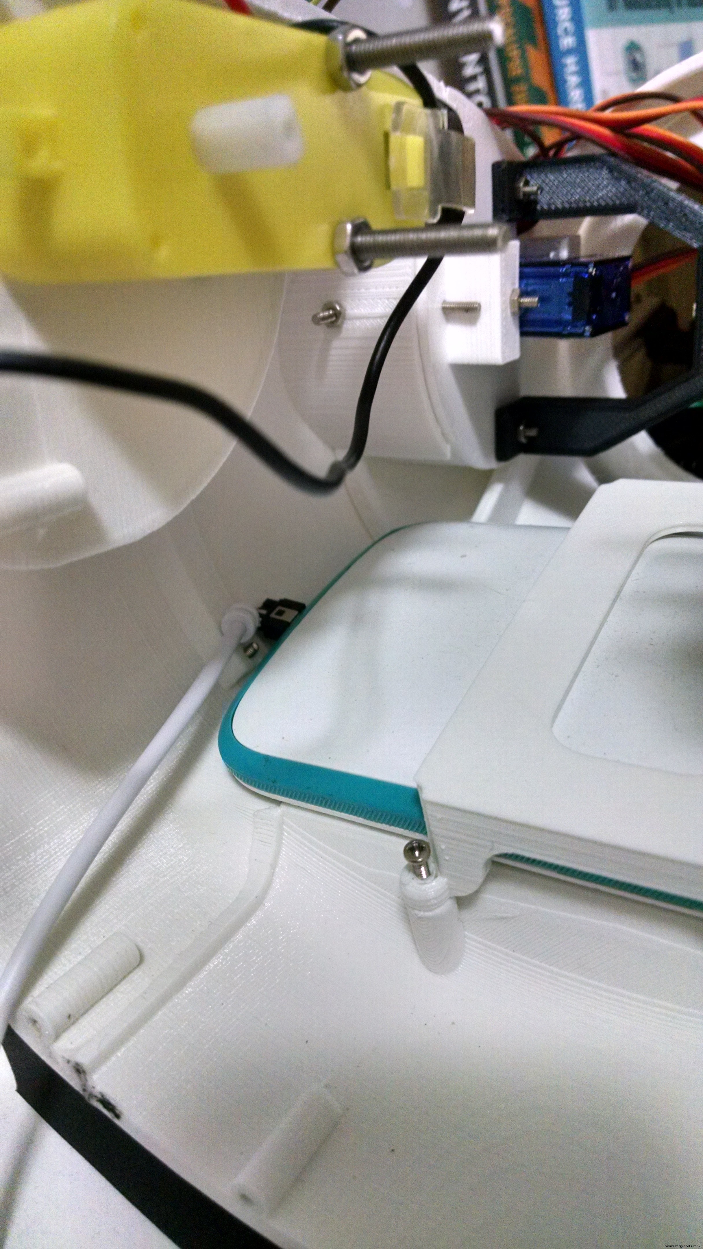
サーボモーター#5をネック軸1に取り付けました。サーボを軸の中央に配置し、ホーンを取り付け、ネジを使用してその位置をロックしました。 2本のM2x6mmボルトを使用して、そのサーボモーターにネック軸2を取り付けました。サーボモーター#6は同じ方法でネック軸2に取り付けられています。
次のステップで示すように、ネック軸2は後でネックセンターに接続されました。
フェイスモジュールはヘッドの内側に取り付けられています。
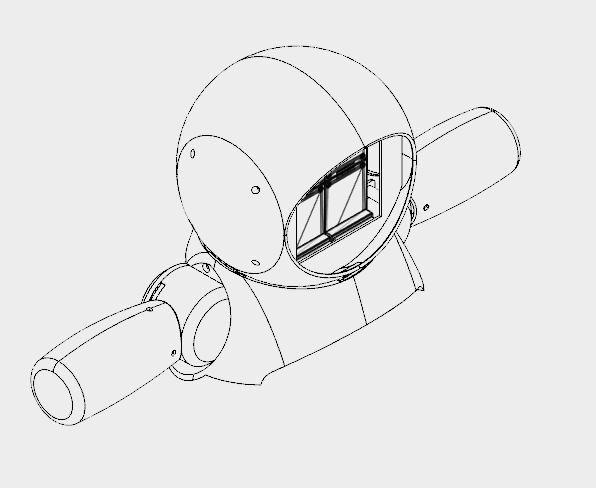
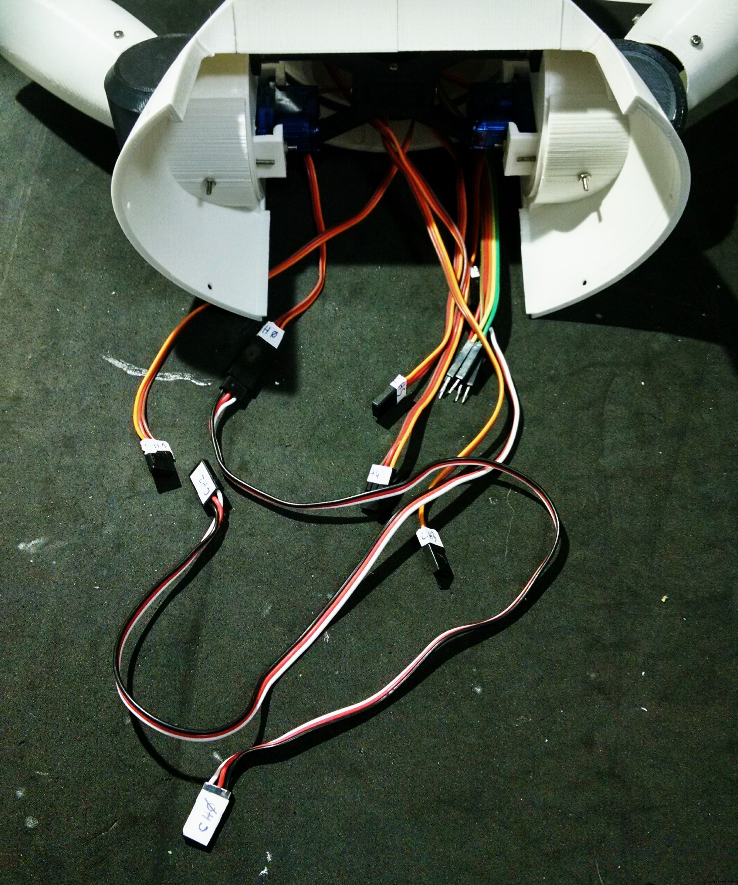
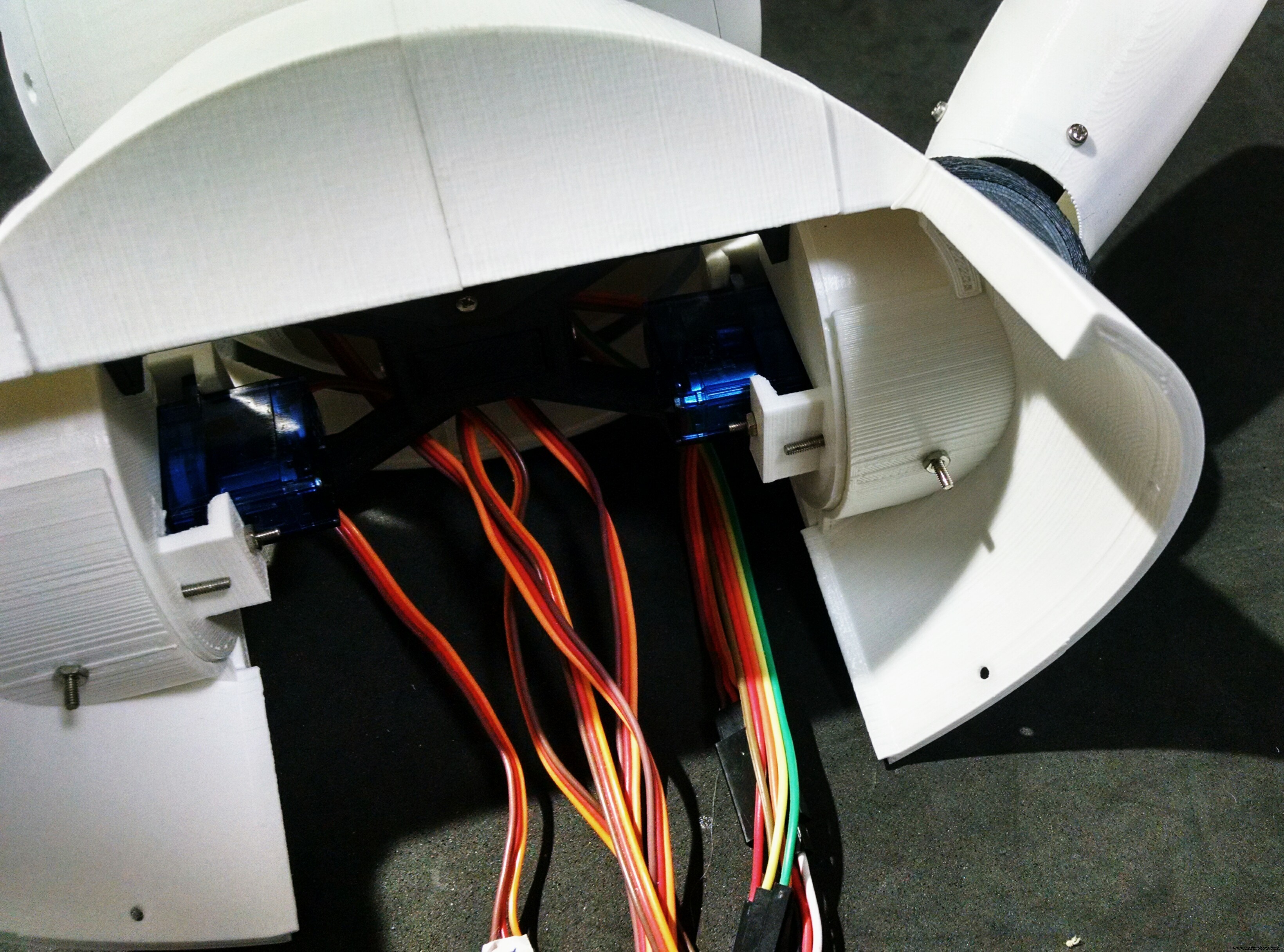
ステップ7:バーストとショルダーの組み立て
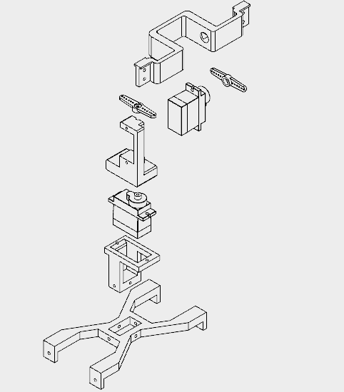
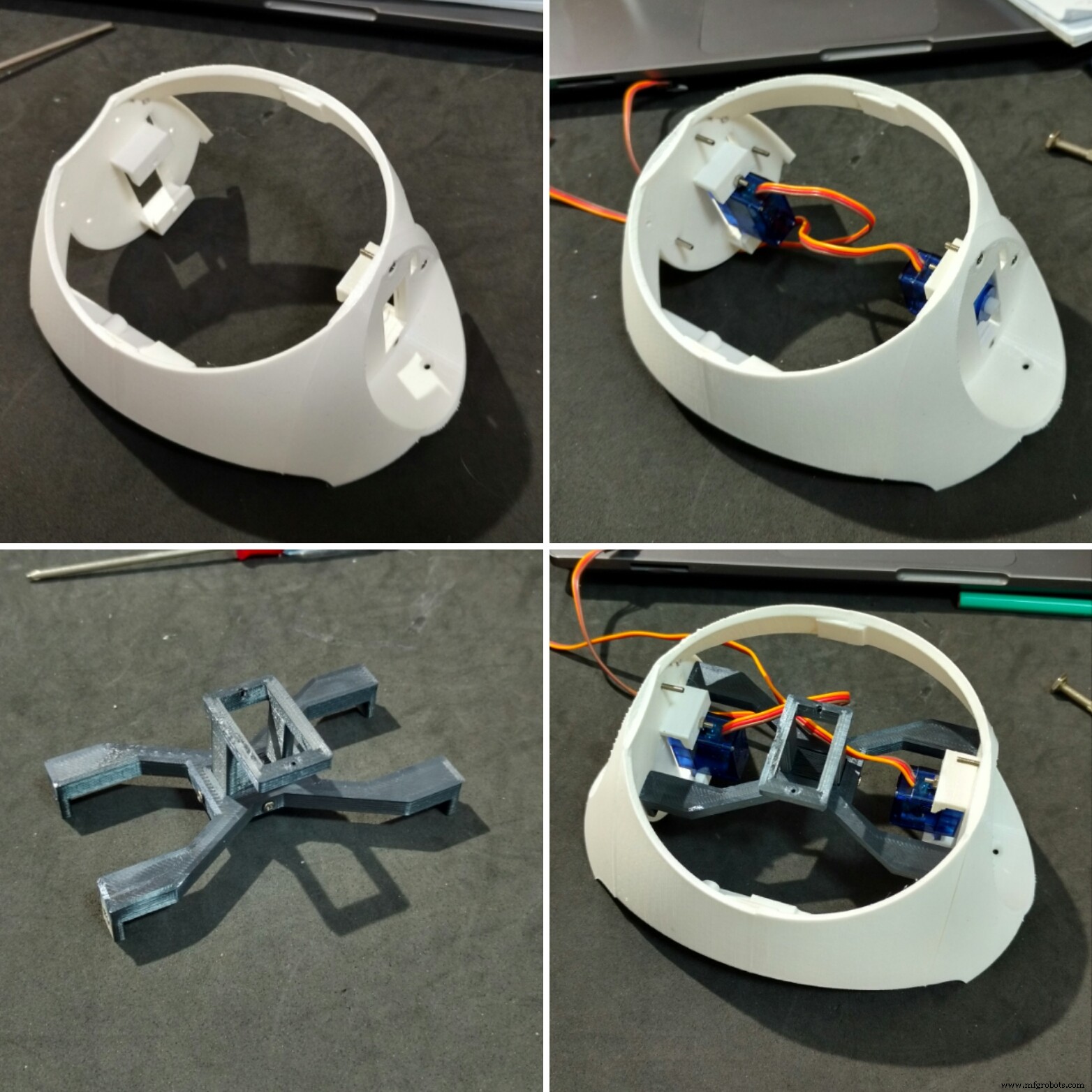

バストと肩は印刷するのに約12時間かかりました。
このセクションは、5つの異なる部分で構成されています。
- バスト(右/左)
- 肩(右/左)
- ネックセンター
- 首軸3
バスト部分は瞬間接着剤を使用して接着されました。肩はM2x10mmボルトを使用して側面に取り付けられ、サーボモーター(サーボモーター#2および#4)が両側に取り付けられました。それらは各肩の長方形の穴を通過し(ワイヤーは実際には通過するのが非常に困難です)、M2x10mmのボルトとナットを使用して取り付けられます。
センターネックには長方形の穴があり、ネック軸3の部分が挿入されています。 4つのM2x6mmボルトを使用して、これら2つのパーツをリンクしました。その後、中央の首が肩に取り付けられました。バストに肩を取り付けるのに使用したのと同じボルトを使用します。 4つのM2x1,5mmナットを使用して、その位置をロックします。
サーボモーター#6は2本のネジを使用してネック軸3に接続されました。次に、ネック軸3をネック中央の長方形の穴の内側に取り付け、4本のM2x6mmボルトを使用してその位置をロックしました。
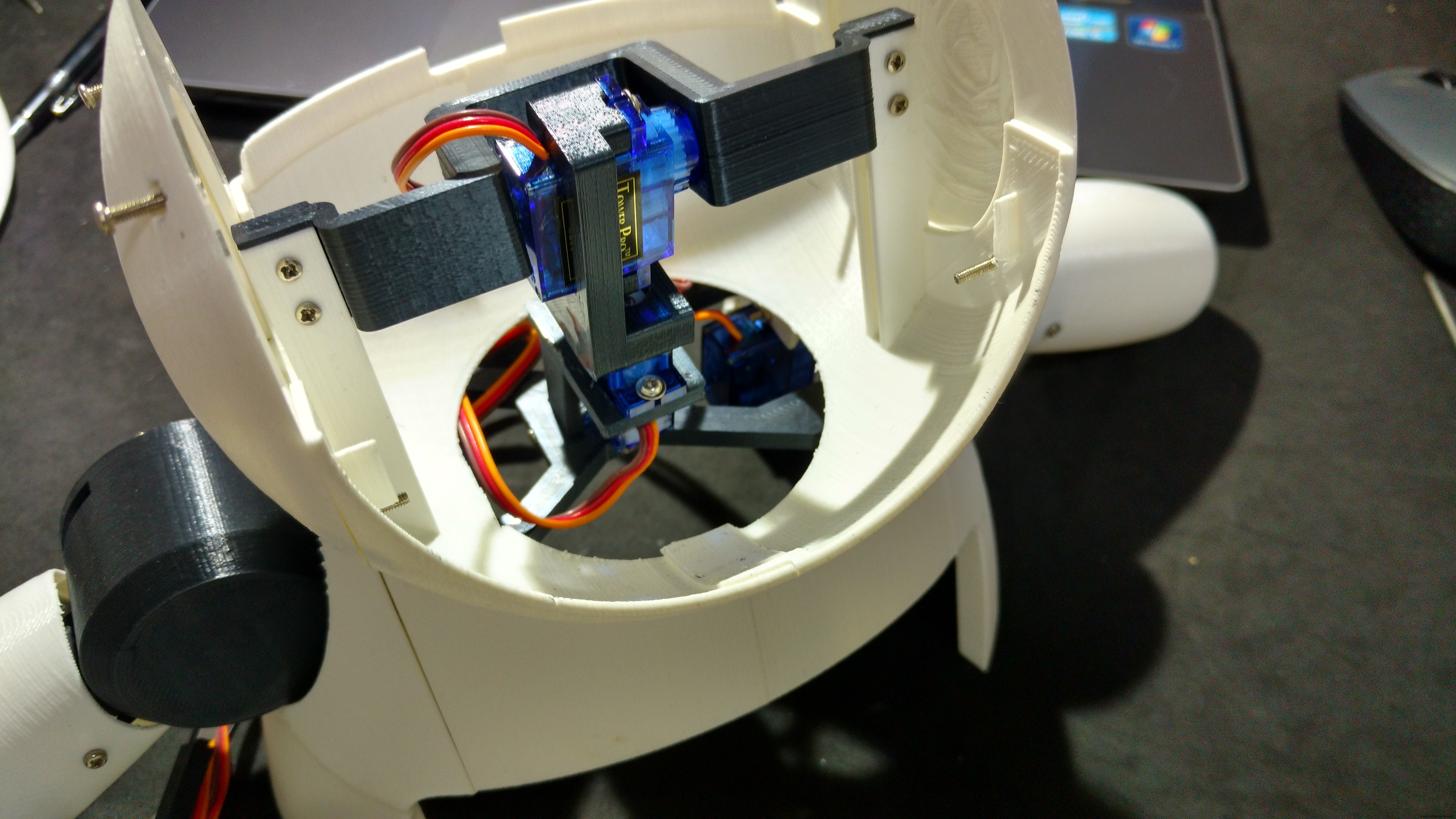
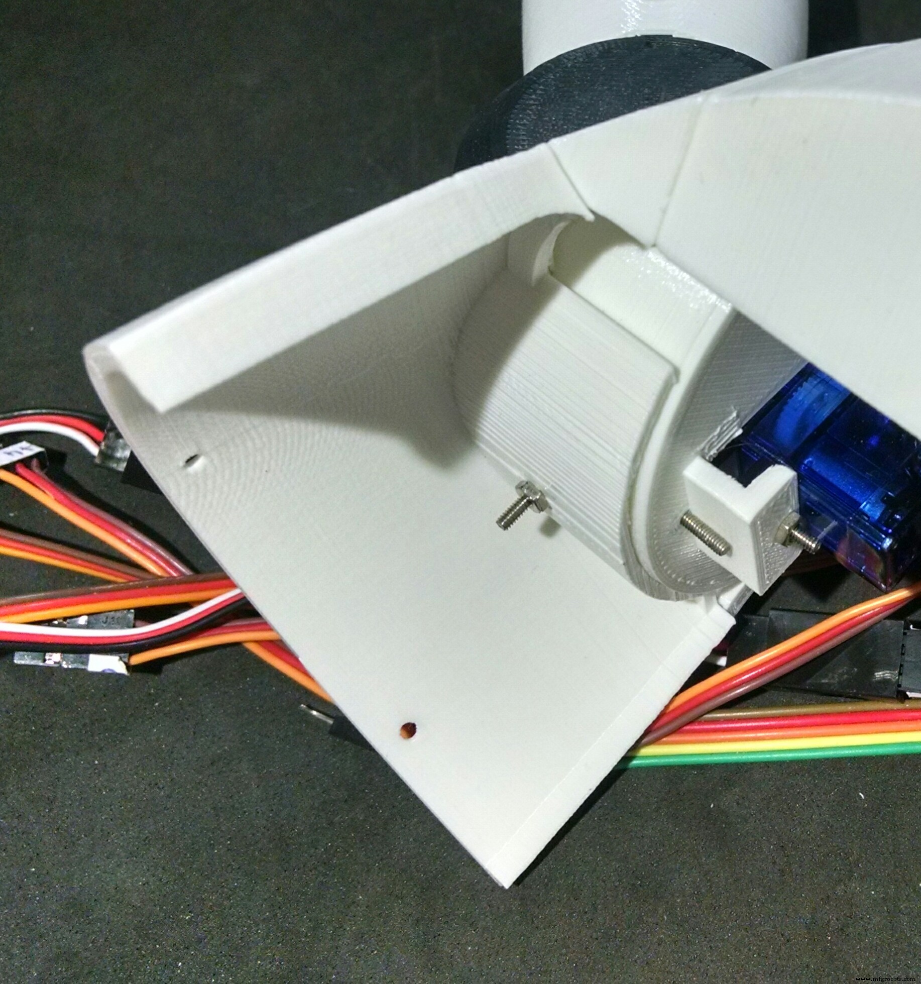
ステップ8:腕を組み立てる
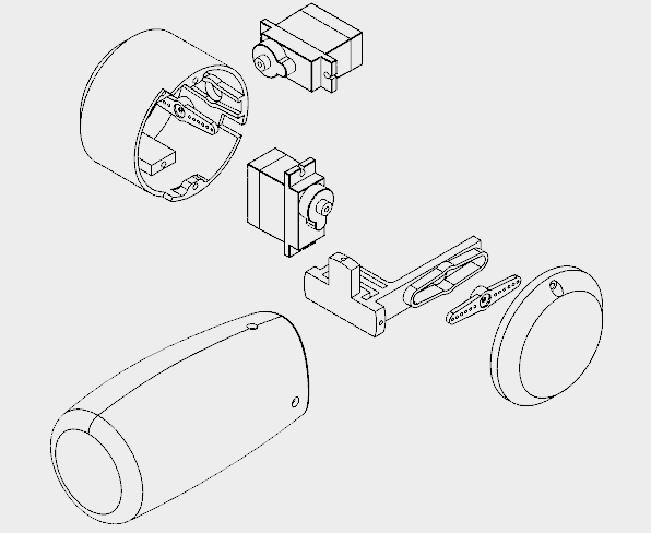

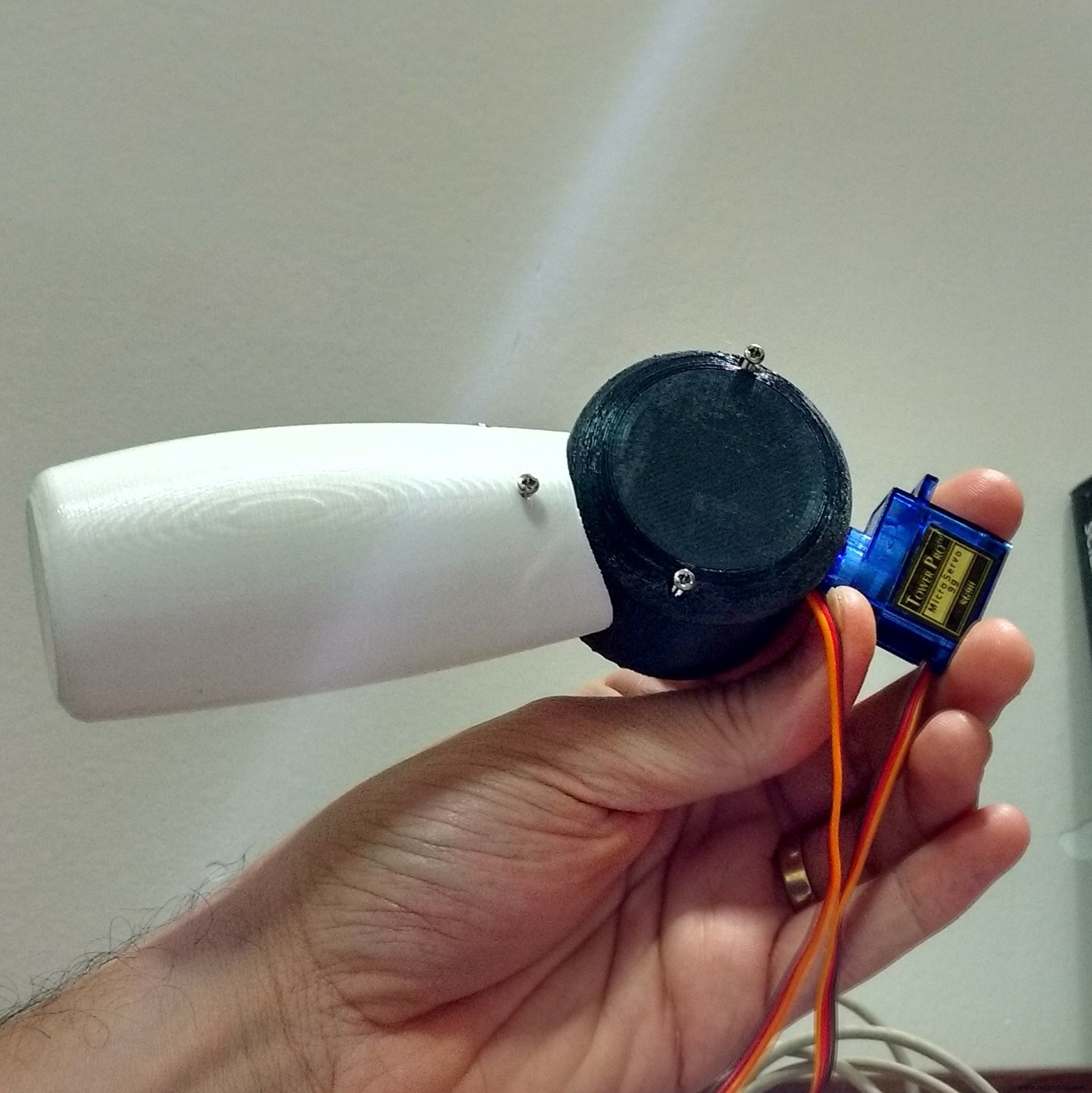
各腕を印刷するのに約5時間かかりました。
各アームは4つの部品で構成されています:
- ショルダーカップ
- ショルダーキャップ
- アーム軸
- 腕
アーム軸は中央に配置され、3本のM2x6mmボルトを使用してアーム自体に取り付けられています。軸のもう一方の端にはサーボホーンが取り付けられています。
ショルダーカップ内にネジを使ってサーボモーター(#1、#3)を取り付け、ホーン(アーム軸に取り付けたもの)を取り付けます。前の手順で示したように、すでに肩に取り付けられているサーボ(#2と#4)に取り付けられている、他のホーンを取り付けるための穴がカップにあります。
サーボのケーブルを通すために、カップ(およびショルダー)に別の穴があります。その後、2本のM2x6mmボルトで、ロボットの肩を閉じるためのキャップを取り付けます。
ステップ9:チェストの取り付け
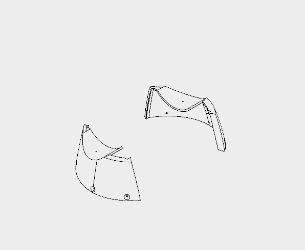
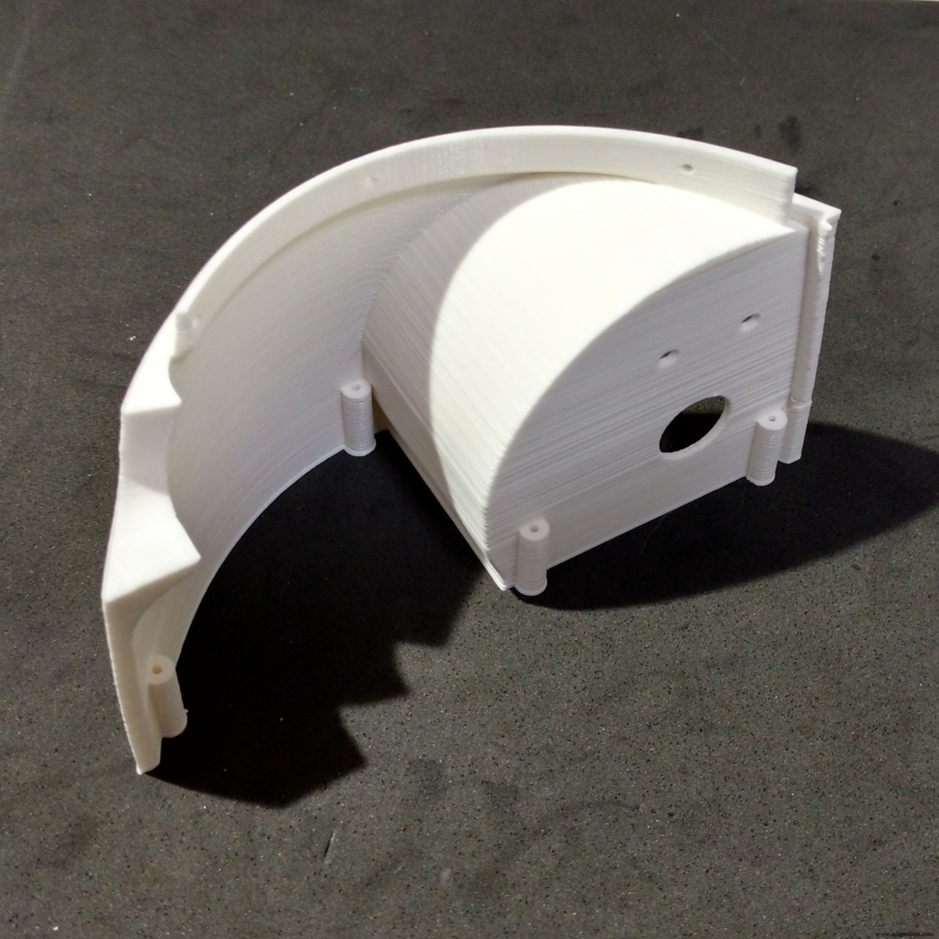
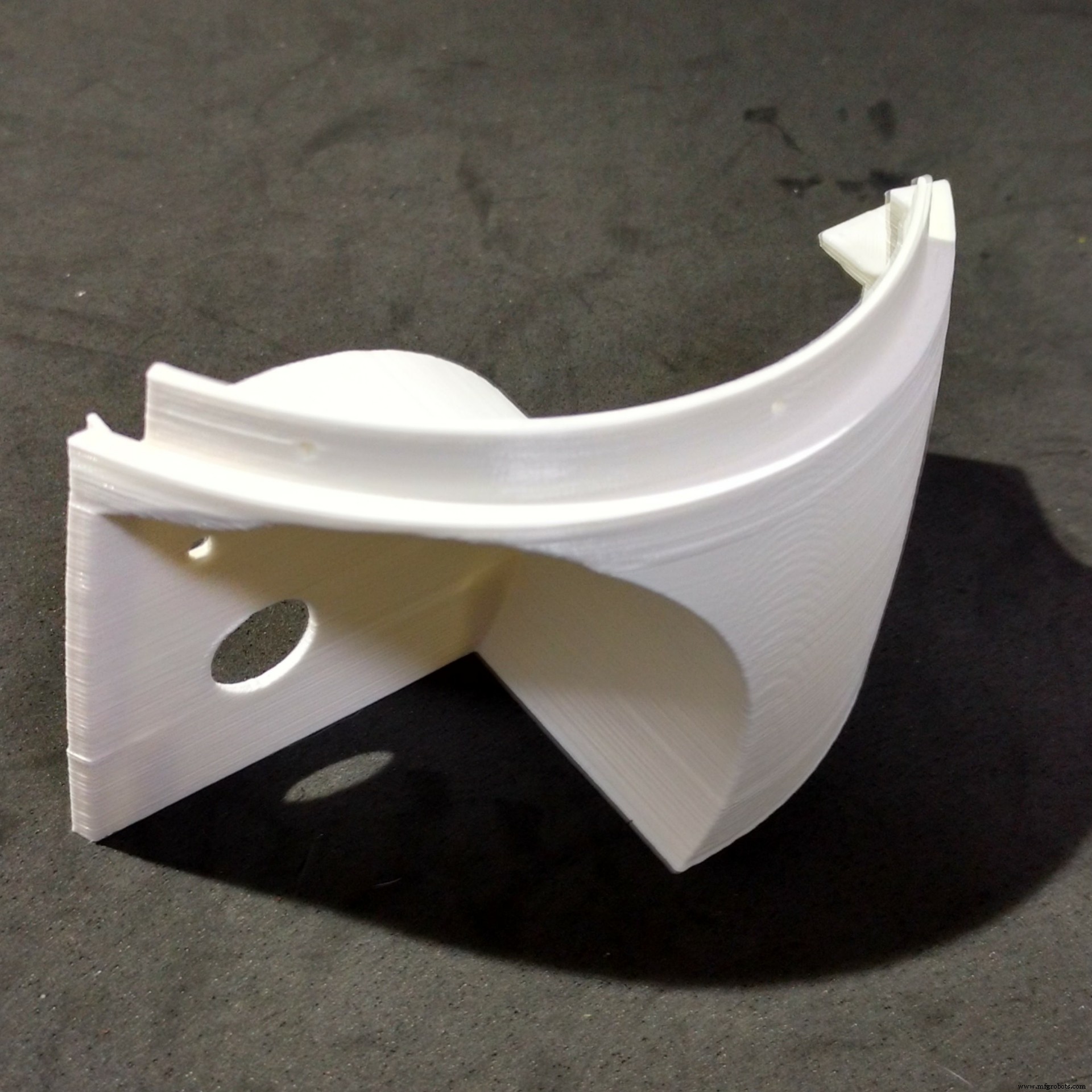
The chest is the part that links the bust to the bottom (wheels and base) of the robot. It's made of only two parts (right and left parts. I printed them in 4 hours.
The shoulders of the robot fits on upper part of the chest. There is a hole for a bolt that helps the alignment and fixation of thos parts. Although it's recomended to glue those two parts.
The bottom of this parts have six holes, which are used for the connection to the wheels, as it will be shown later.
At this point I labelled the servomotors with some stickers, in order to make the connection of the circuits easier.
Step 10:Assembling the Wheels
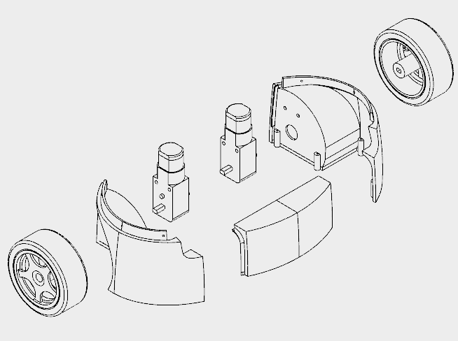
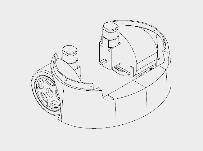
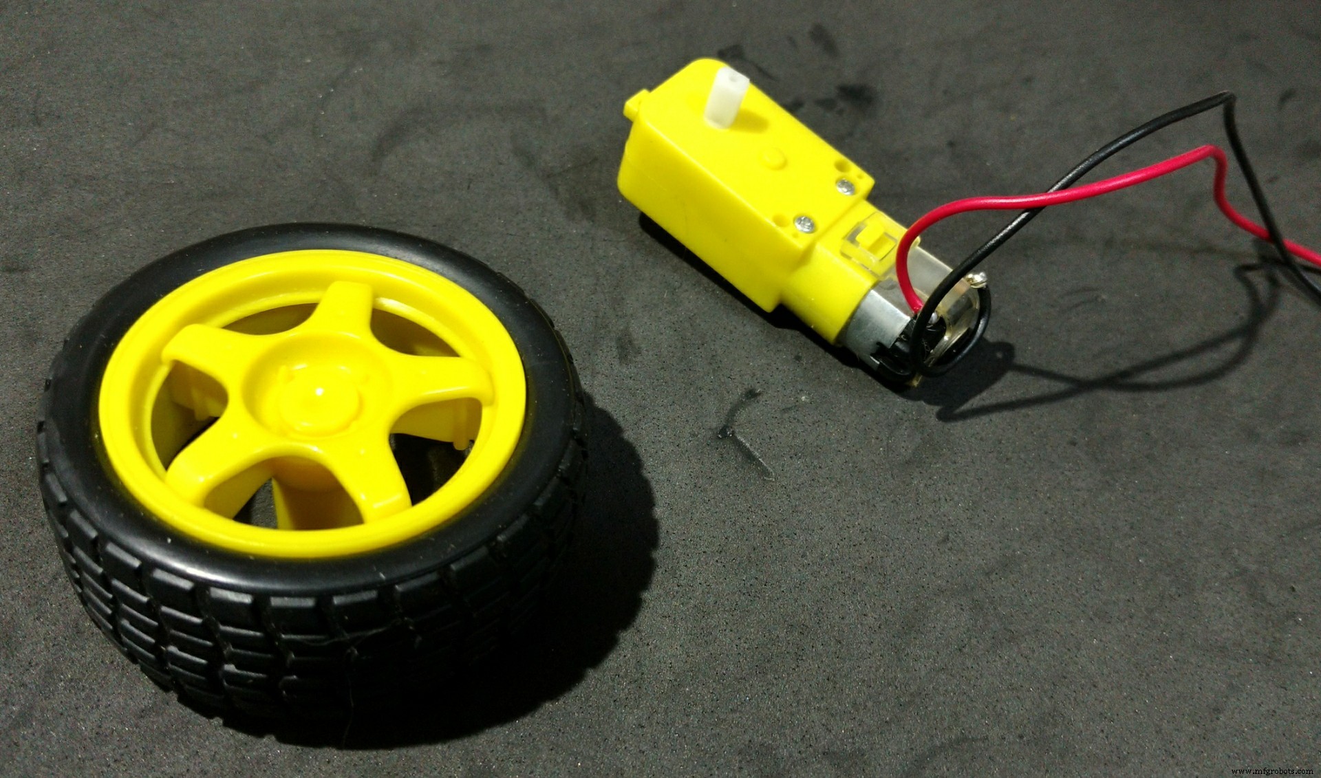
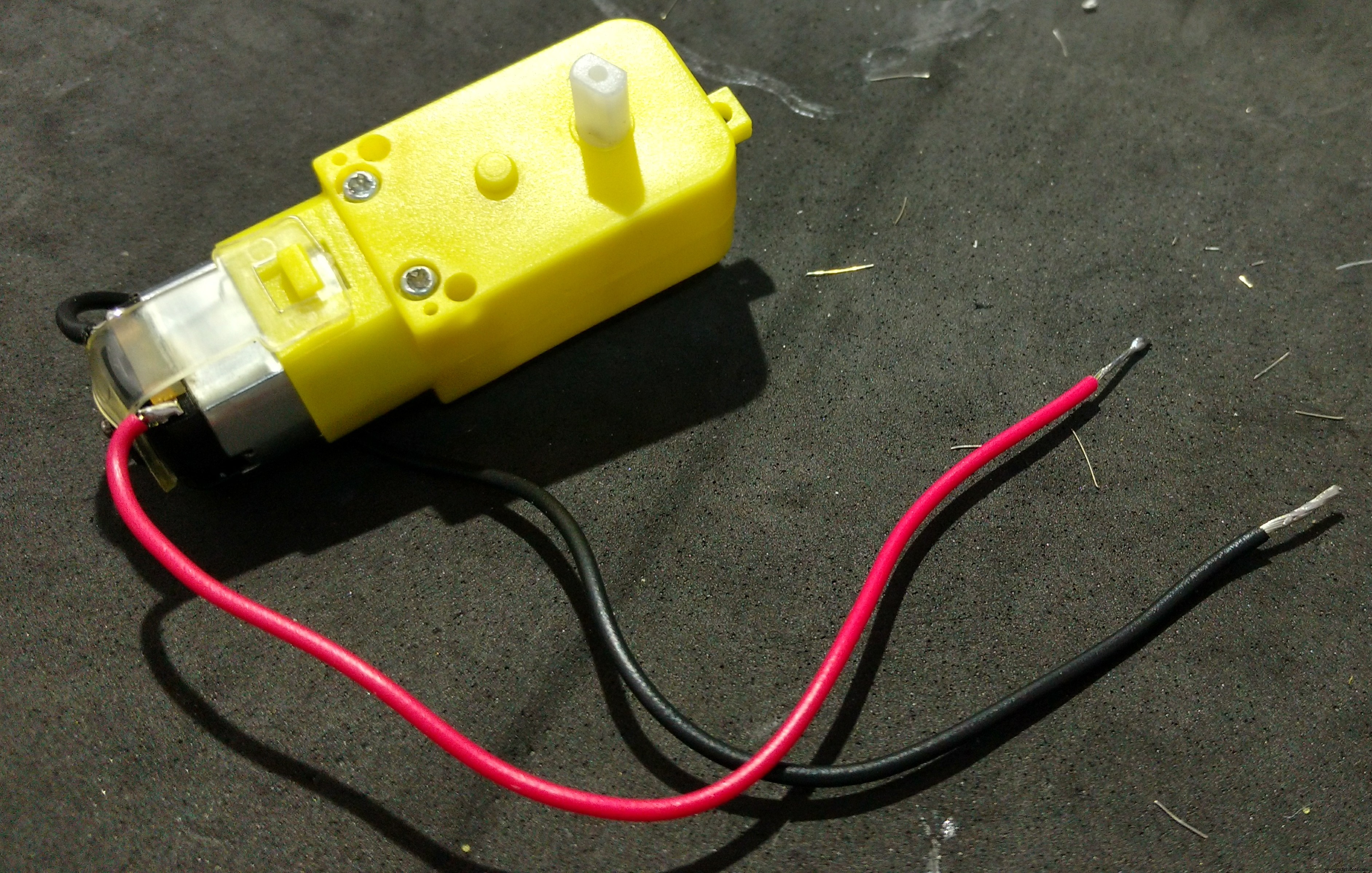

The wheels of the robot uses three 3d printed parts:
- Wheels (left/right)
- フロント
It took me around 10h to print those parts.
I followed the following steps for assembling the wheels:
- First I had to solder some wires to DC motors connectors. Those wires were later used for powering the motors using a H-bridge circuit;
- The motors were then attached to the structure using two M3x40 bolts and nuts for each. Actually a shorter bolt might be used (but I found none online);
- After that I glued the front pannel, which links the other parts of the structure;
- This part has some holes on its top. They are used for its attachment to the chest, shown previously. Six M2x6mm bolts were used for the connection of both sections.
Step 11:Phone Holder
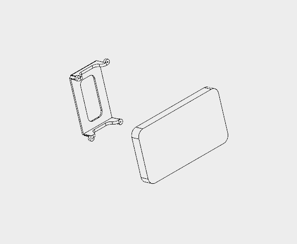

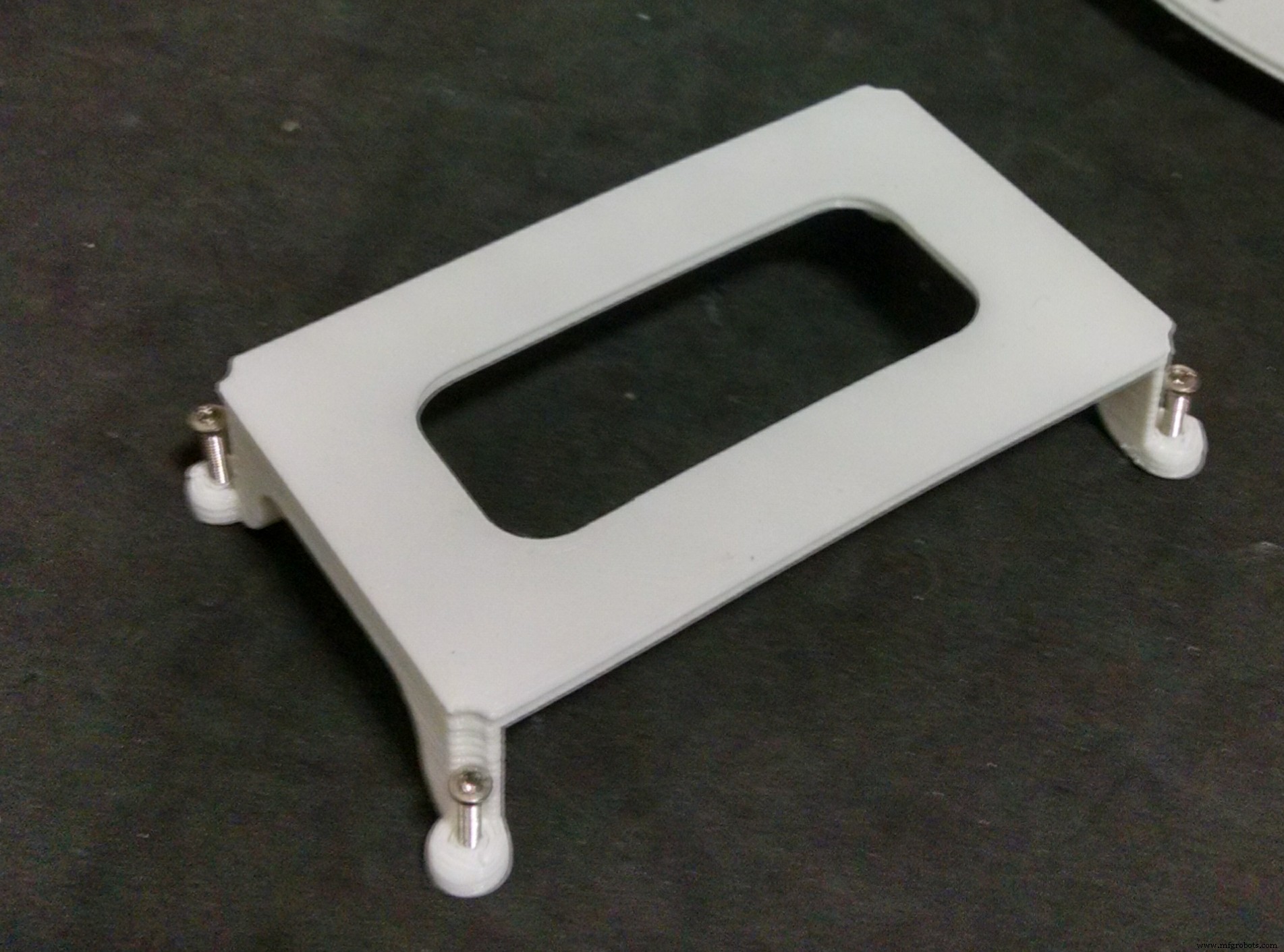
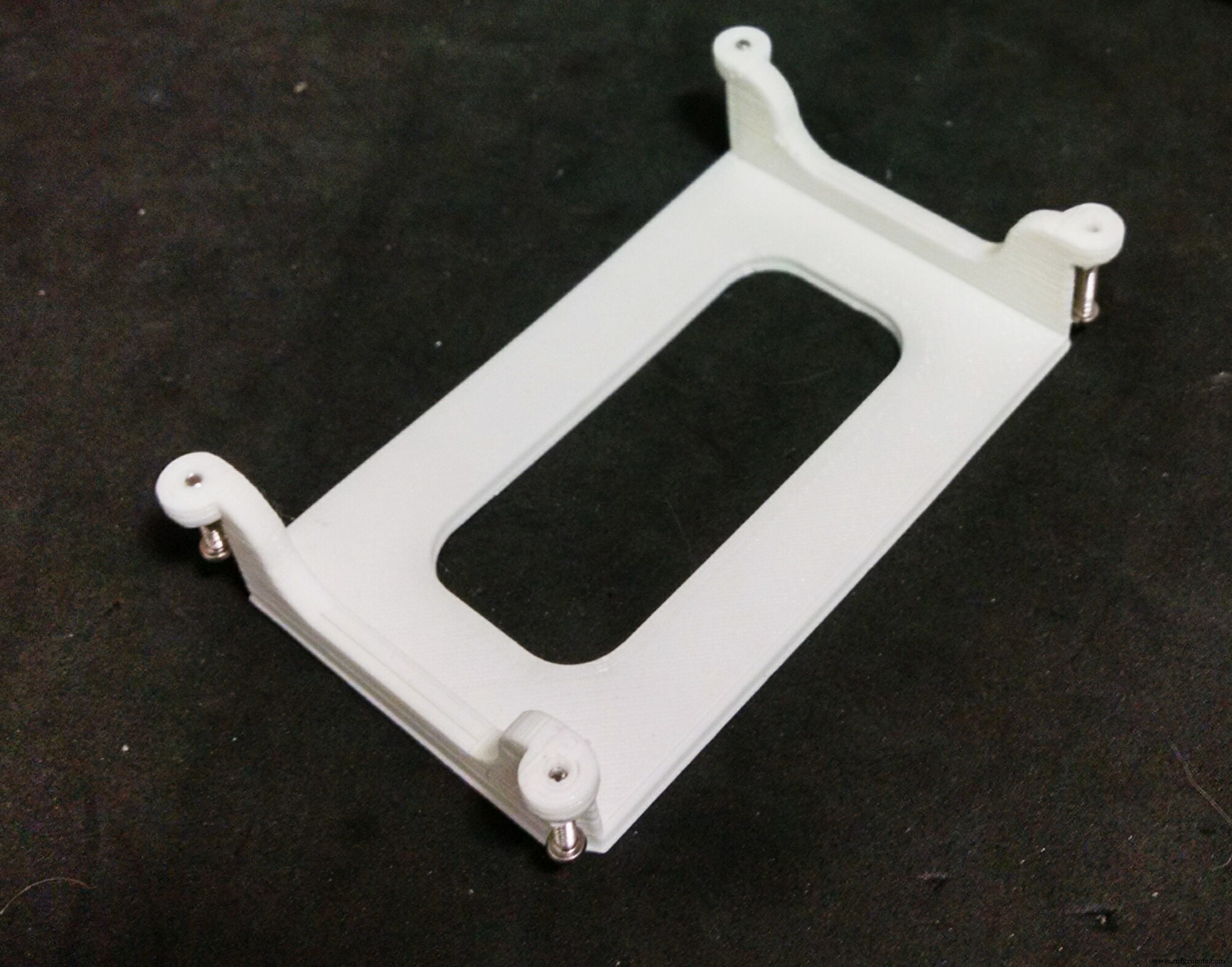
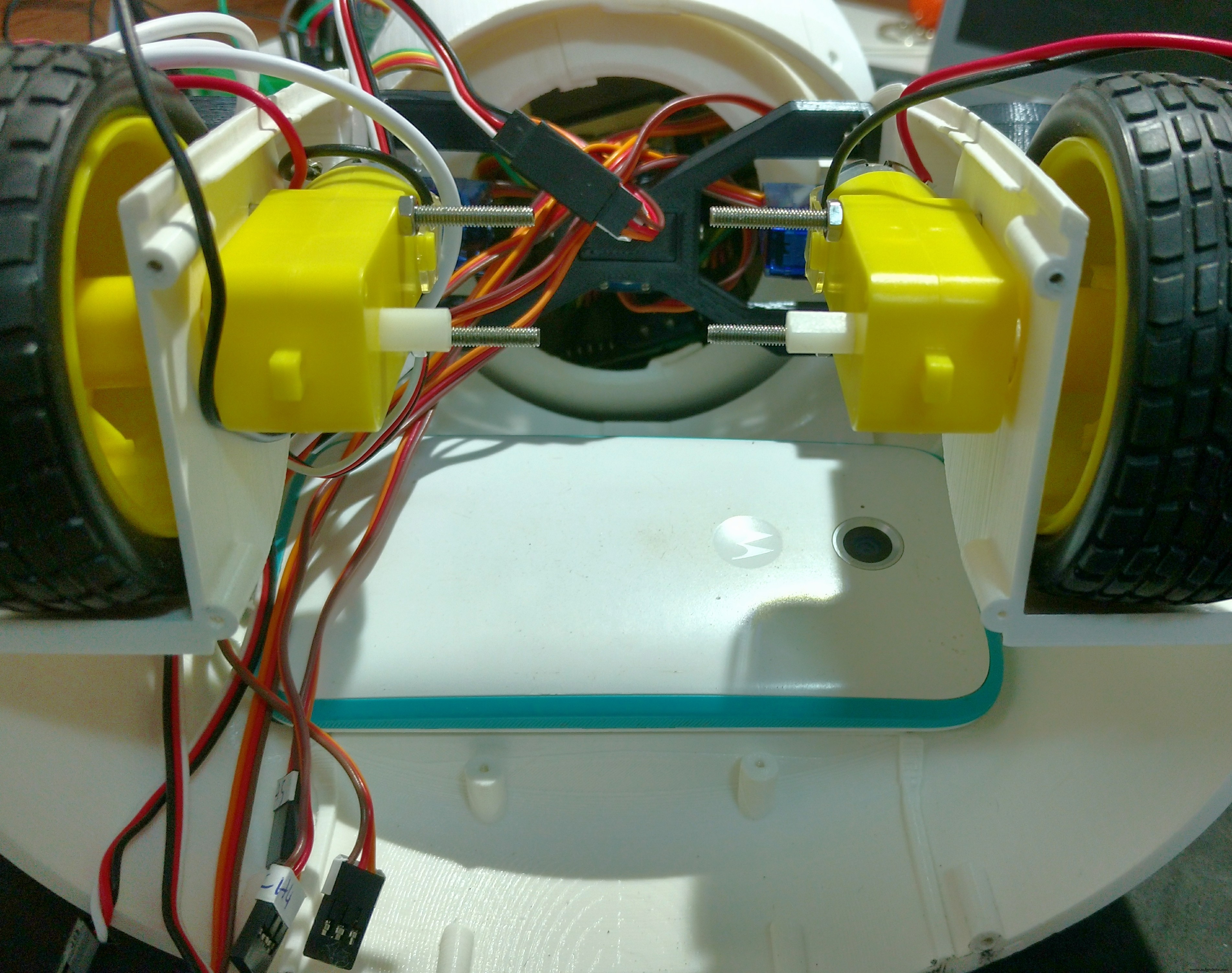
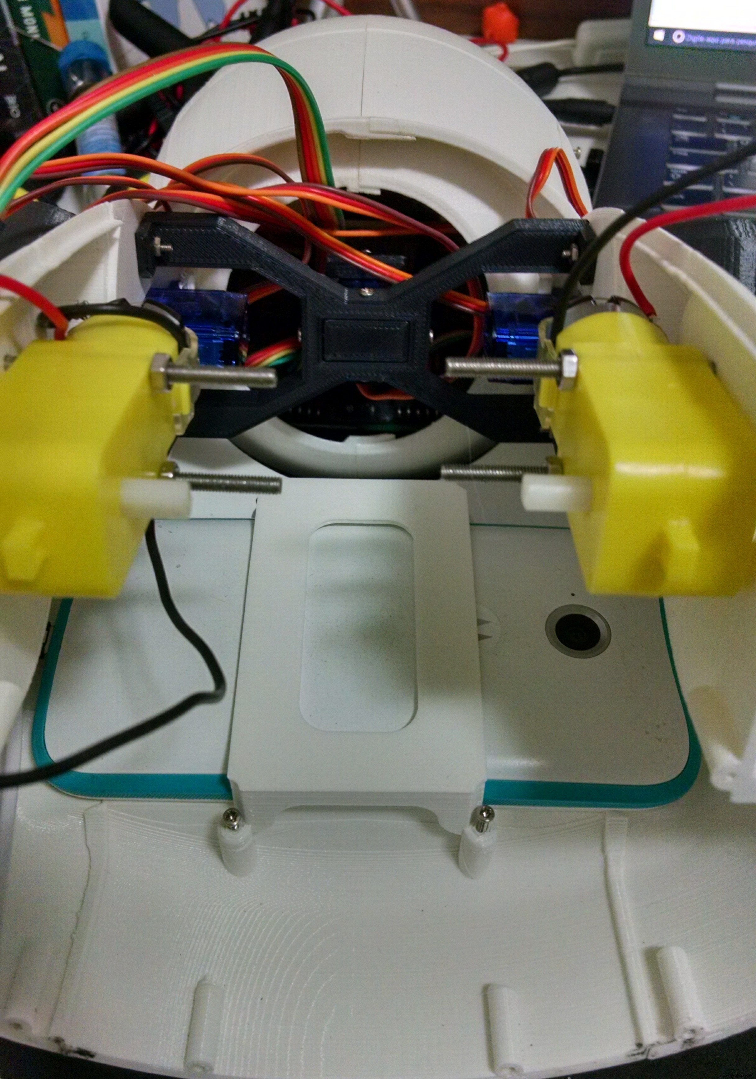
The phone holder is a single 3d printed part, and it takes around 1 hour to print.
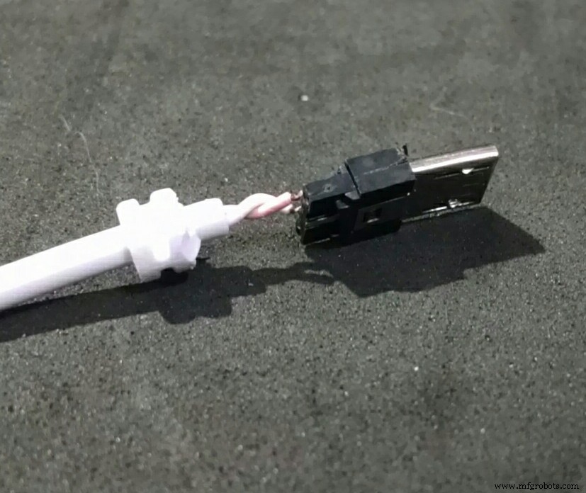
The robot has a smartphone at it's belly. It was designed for a Motorola Moto E. It has a 4.3" display. Other smartphones with similar size might fit as well.
The phone holder part is used to hold the smartphone in the desired position. First the smart phone is positioned, then it's pressed against the body of the robot using the phone holder and four M2x6mm bolts.
It's importart to connect the USB cabe to the smartphone before tightening the bolts. Otherwise it will be hard to connect it later. Unfortunatly the space is very limited, so I had to cut part of the USB connector away... :/
Step 12:Mounting the Base
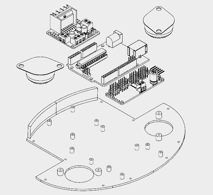
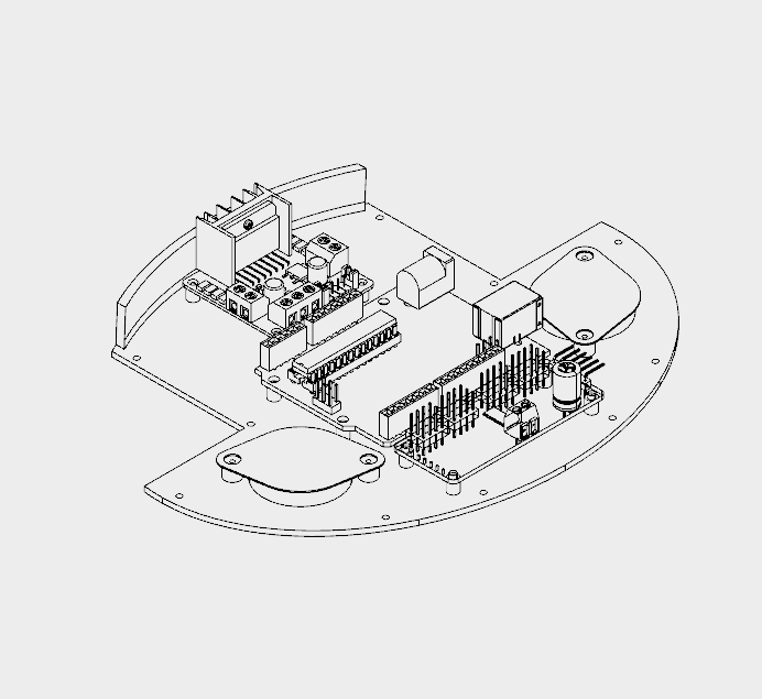
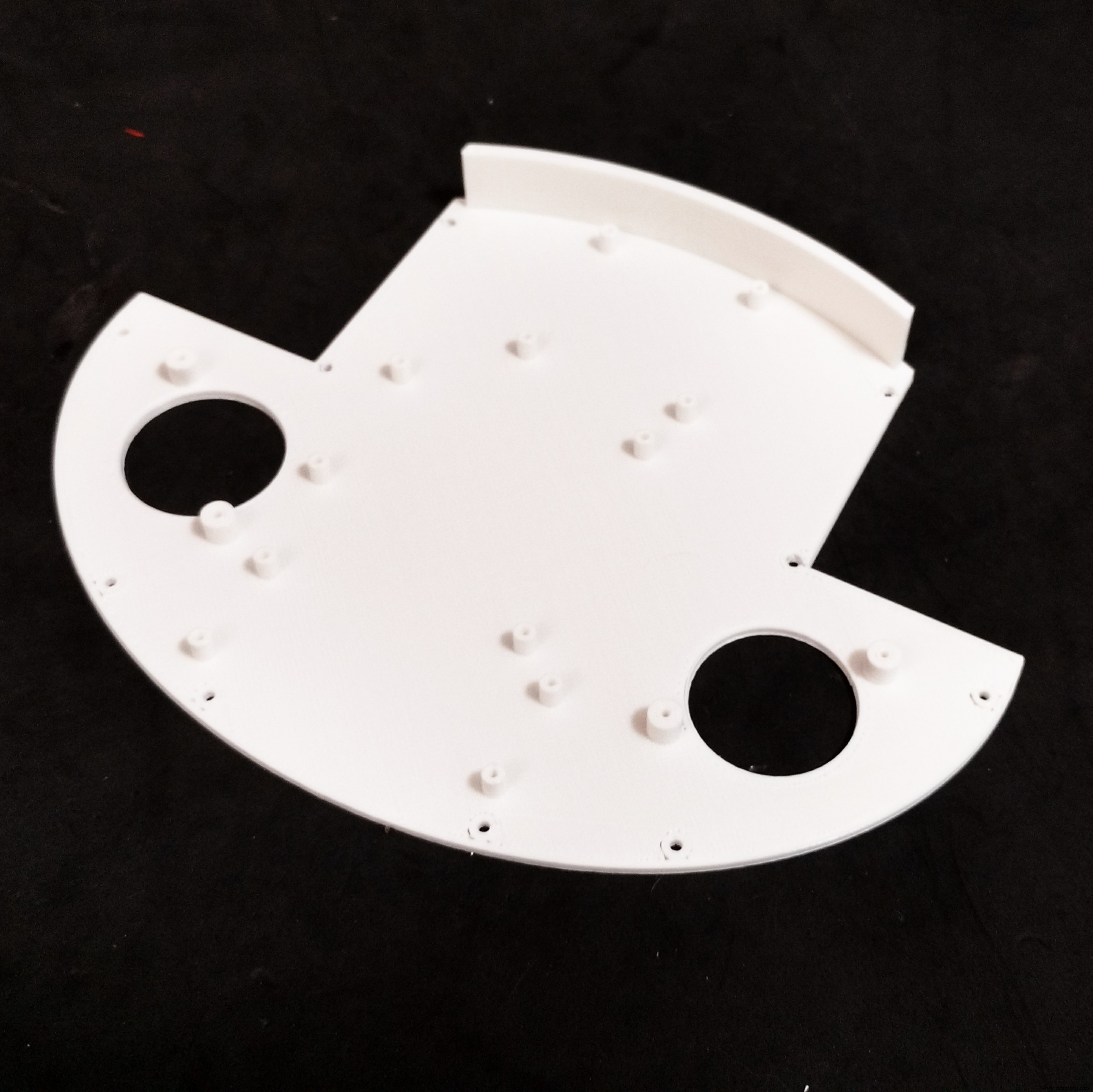
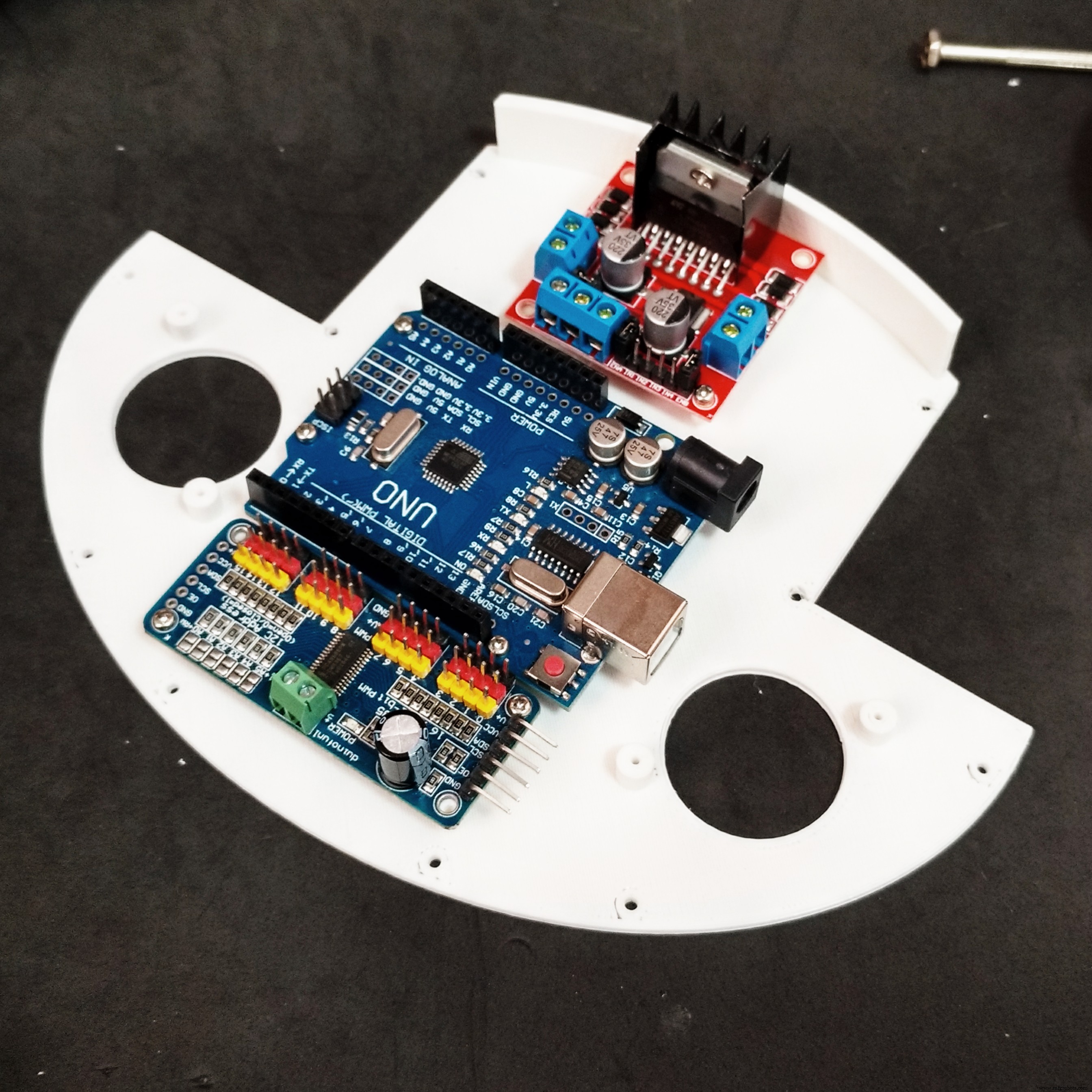
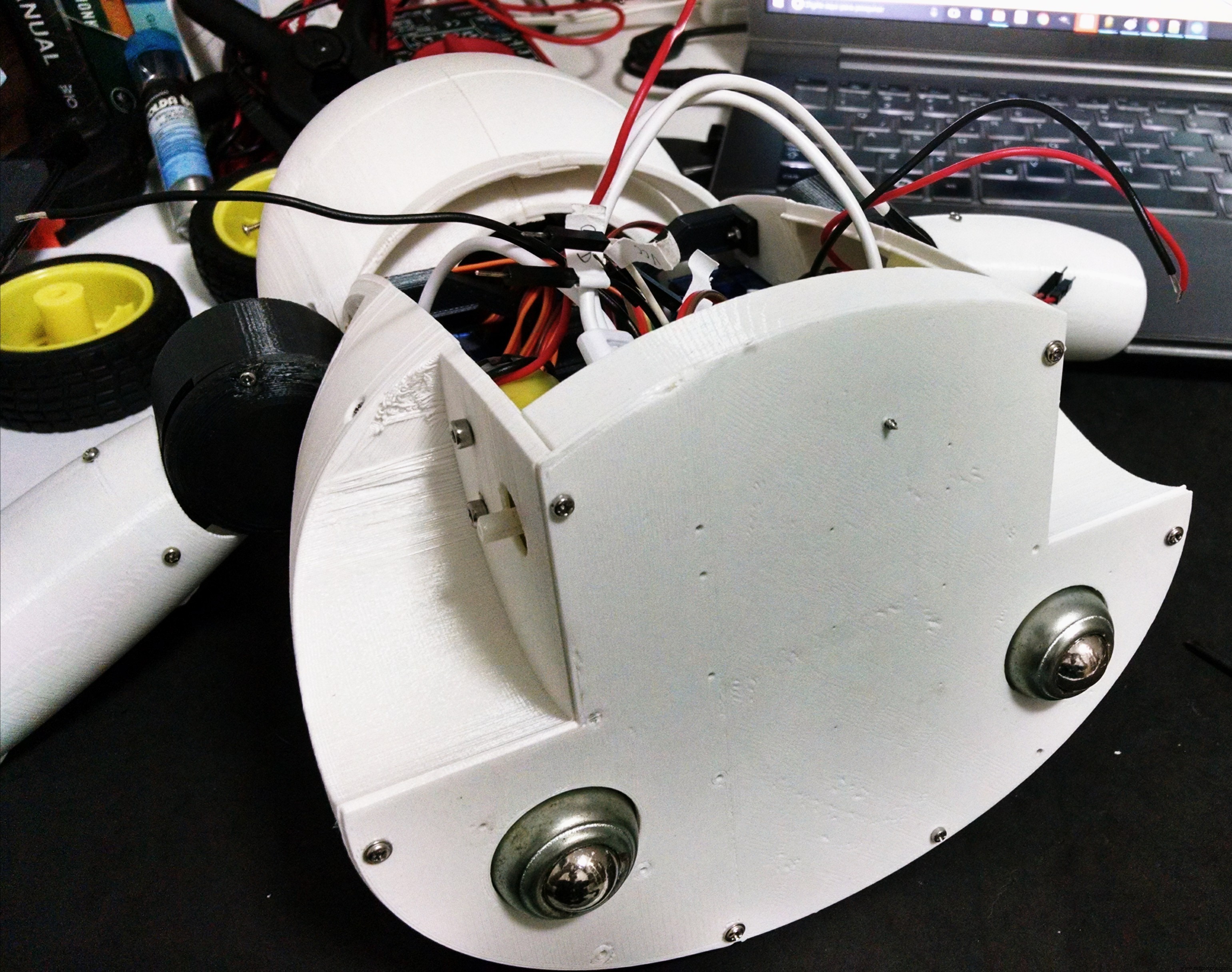
The base has only one 3D printed part. It took me around 4h to print that part.
It has several holes for the installation of other components, like the ball wheels, and circuit boards for instance. The following procedure was used for assembling the base:
- Install the 16 channel servo controller using four M2x6mm bolts;
- Install the L298N h-bridge circuit using four M2x6mm bolts;
- Install the Arduino Uno using four M2x6mm bolts;
- Install the protoshield on the top of the robot;
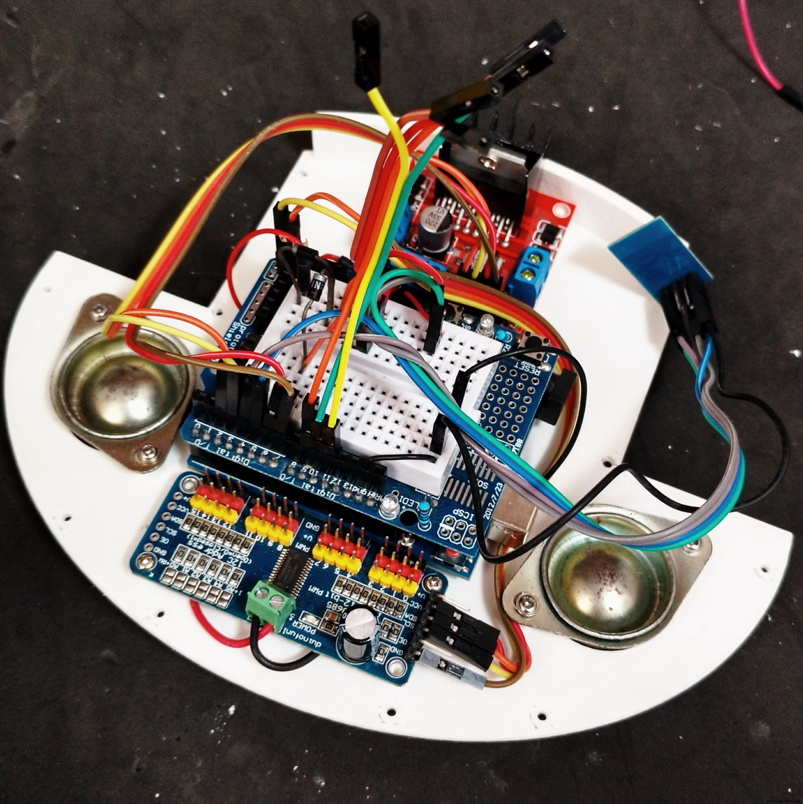
- Wire up the circuits (as it's described a couple steps later);
- Installe the ball wheels using two screws for each one. The wires were arranged so that they are traped between the base and the screws used in the installation of the wheels;
- Base was attached to wheels section using some screws.
Step 13:Back and Power Pack
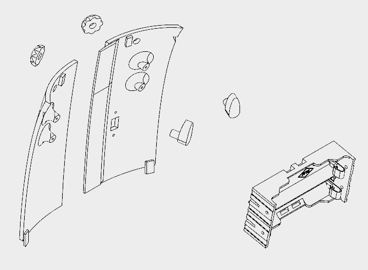


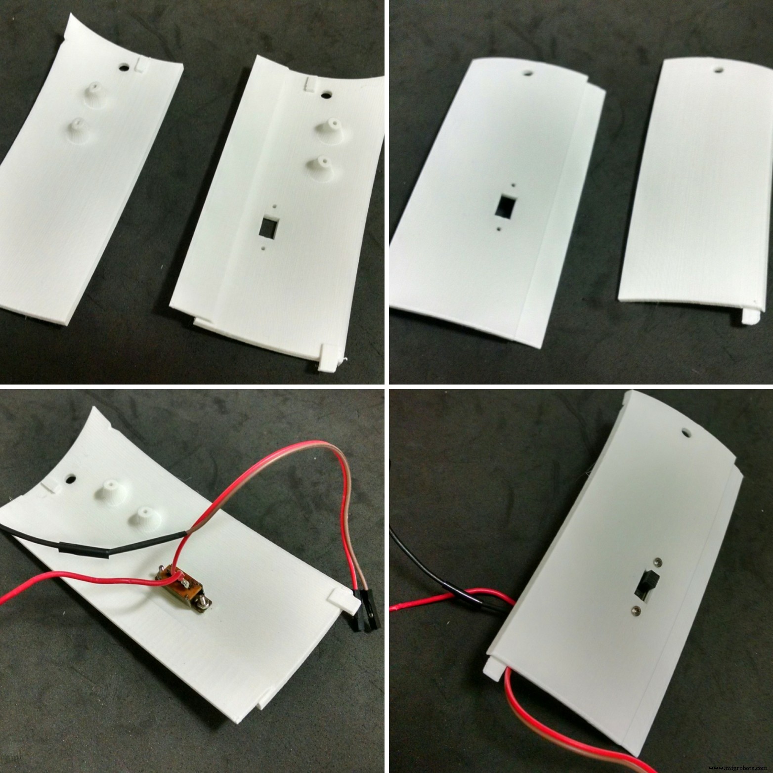

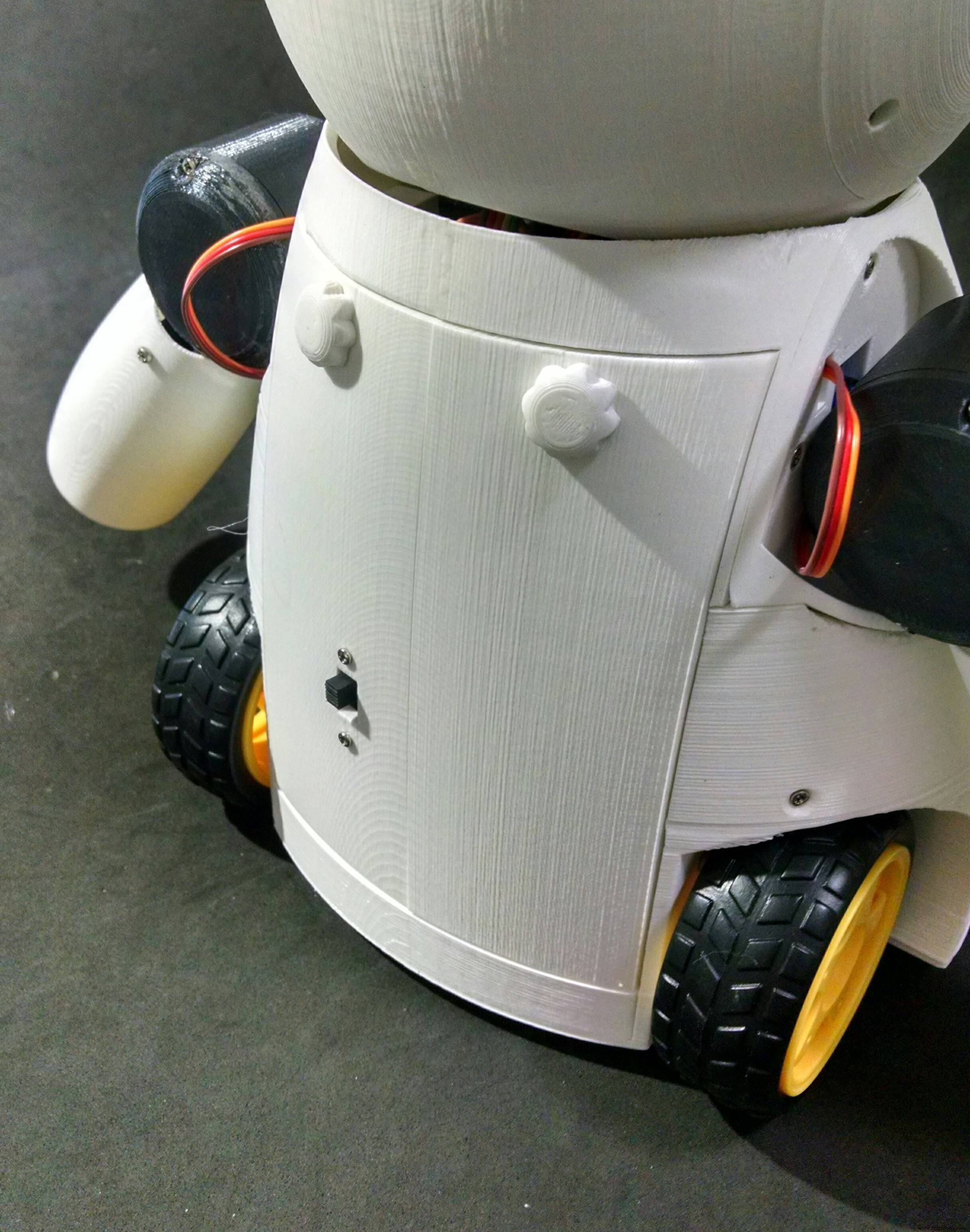
The back cover of the robot was designed so that one can easilly open it for accessing the circuits, recharging the batteries, or turning the smartphone on/off.
It's made of six 3d printed parts:
- Back (left/right)
- Knobs (x2)
- Locks (left/right)
It took me around 5h30 for printing the parts. Right and left back parts were glued using superglue. Wait until the glue is completly dry, or the cover will break easilly.
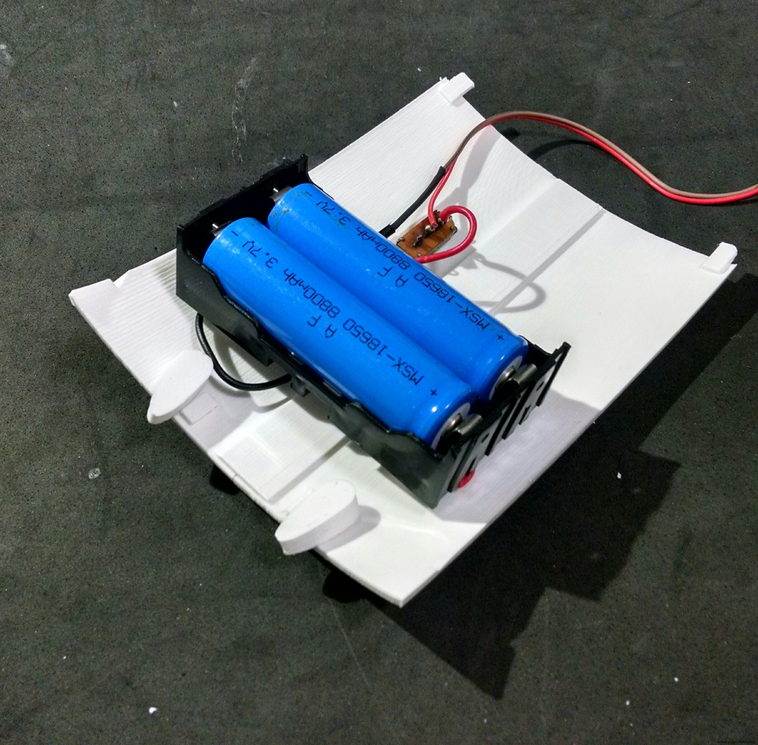
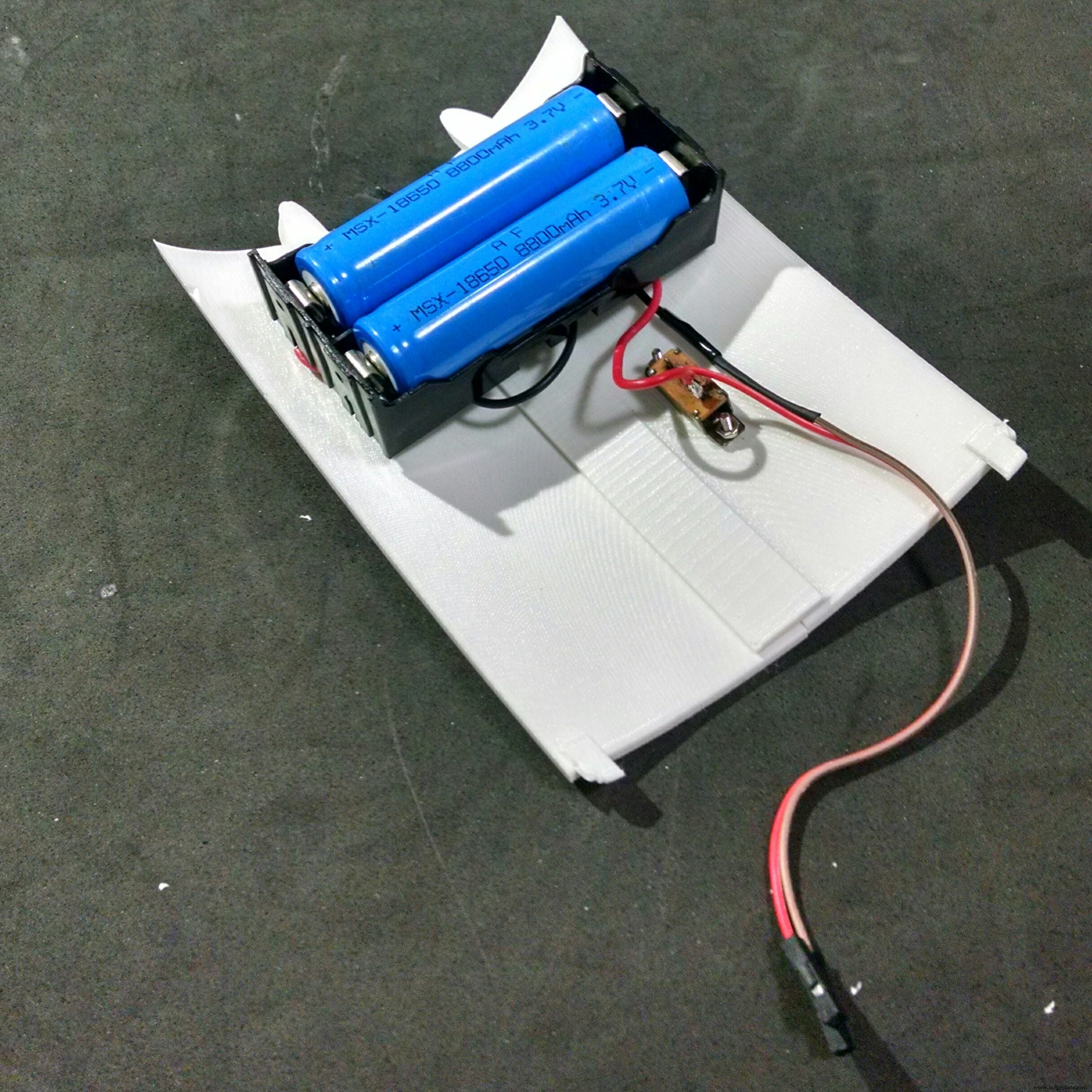
The power pack consists of two 18650 batteries and a battery holder. I had to solder some wires (between battery #1 negative pole and battery #2 positive pole). The negative pole of the power pack was connected to Arduinos GND (using some wires and jumpers). A on/off swich was installed between the positive pole and Arduino's Vin input.
The on/off switch was attached to back 3d printed parts using a M2x6mm bolt and M2x1.5mm nut. The battery holder was attached to the back using four M2x6mm bolts.
The cilindrical part of the locks had to be sanded with a sand paper for a better fitting. They pass through the holes on the cover. The knobs are connected and glued on the other side.
The cover fits to the back of the robot. The knobs can be turned for locking the lid, protecting the insides of the robot.
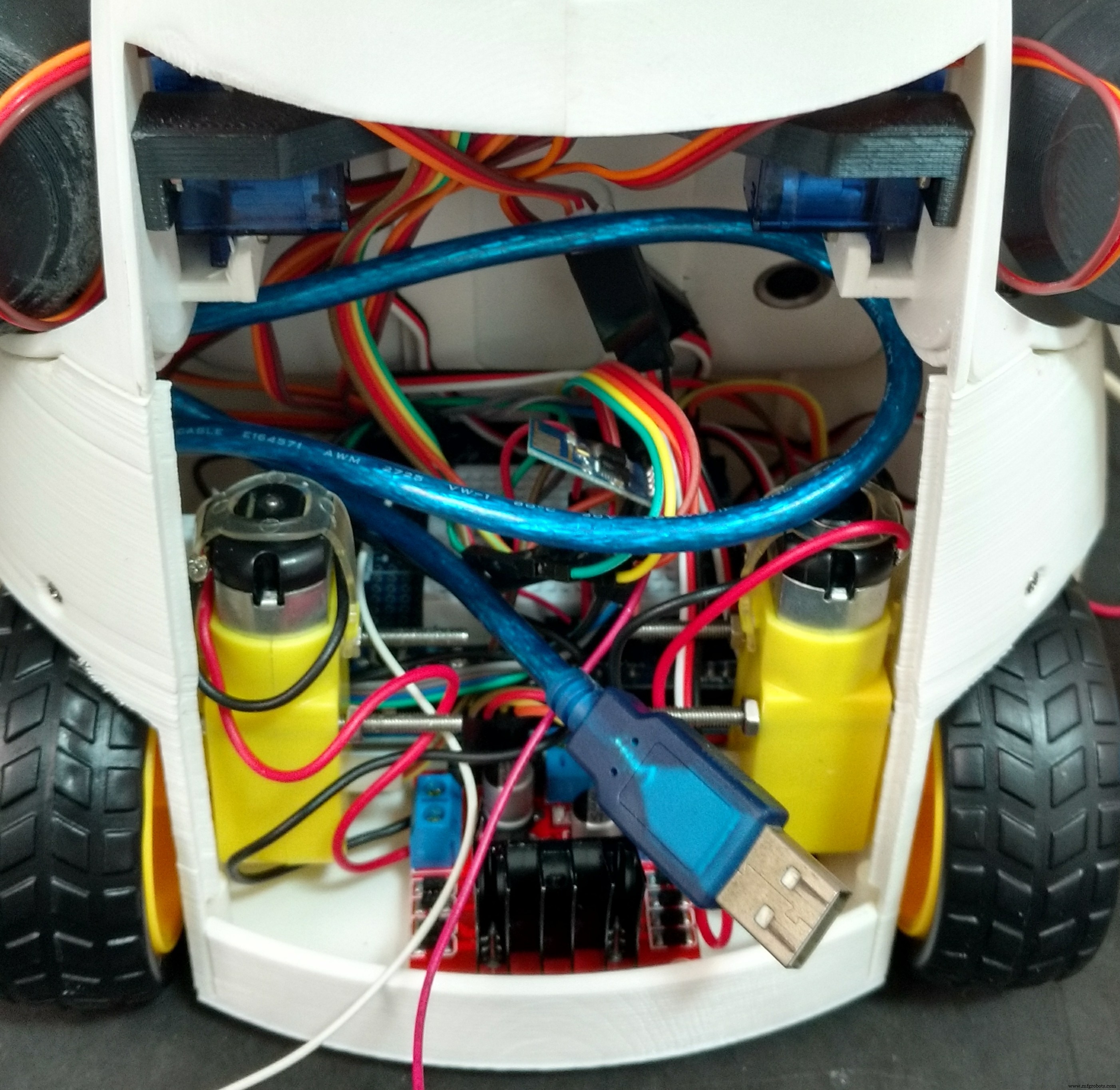
Step 14:Wiring Up the Circuits

The circuit was wired up according to the schematics.
Arduino:
- Arduino pin D2 => L298N pin IN4
- Arduino pin D3 => L298N pin IN3
- Arduino pin D6 => L298N pin IN2
- Arduino pin D7 => L298N pin IN1
- Arduino pin D9 => MAX7219 pin DIN
- Arduino pin D10 => MAX7219 pin CS
- Arduino pin D11 => MAX7219 pin CLK
- Arduino pin D4 => ESP8266 RXD
- Arduino pin D5 => ESP8266 TXD
- Arduino pin A4 => SDA
- Arduino pin A5 => SCL
- Arduino pin Vin => Battery V+ (before diodes)
- Arduino pin gnd => Battery V-
ESP8266-01
- ESP8266 pin RXD => Arduino pin D4
- ESP8266 pin TXD => Arduino pin D5
- ESP8266 pin gnd => Arduino pin gnd
- ESP8266 pin Vcc => Arduino pin 3V3
- ESP8266 pin CH_PD => Arduino pin 3V3
L298N h-bridge
- L298N pin IN1 => Arduino pin D7
- L298N pin IN2 => Arduino pin D6
- L298N pin IN3 => Arduino pin D3
- L298N pin IN4 => Arduino pin D2
- L298N pin +12V => Battery V+ (after diodes)
- L298N pin gnd => Arduino gnd
- L298N OUT1 => Motor 1
- L298N OUT2 => Motor 2
MAX7219 (first matrix)
- MAX7219 pin DIN => Arduino pin D9
- MAX7219 pin CS => Arduino pin D10
- MAX7219 pin CLK => Arduino pin D11
- MAX7219 pin Vcc => Arduino pin 5V
- MAX7219 pin gnd => Arduino pin gnd
MAX7219 (other matrixes)
- MAX7219 pin DIN => MAX7219 pin DOUT(previous matrix)
- MAX7219 pin CS => MAX7219 pin CS (previous matrix)
- MAX7219 pin CLK => MAX7219 pin CLK (previous matrix)
- MAX7219 pin Vcc => MAX7219 pin VCC (previous matrix)
- MAX7219 pin gnd =:MAX7219 pin gnd (previous matrix)
16-channel servo controller
- Servo controller pin SCL => Arduino pin A5
- Servo controller pin SDA => Arduino pin A4
- Servo controller pin Vcc => Arduino pin 5V
- Servo controller pin gnd => Arduino pin gnd
- Servo controller pin V+ => Battery V+ (after diodes)
- Servo controller pin gnd => Arduino pin gnd
Some say the Sg90 servo can be powered between 3.0 and 6.0V, others between 4.0 and 7.2V. To avoid trouble I decided to put two diodes in series after the batteries. This way, the voltage for servos is 2*3.7 - 2*0.7 =6.0V. The same is applied to the DC motors.
Notice this is not the most efficient way, but it worked for me.
robot%2Bmk0%2B-%2Brev8_bb.pdf robot%2Bmk0%2B-%2Brev8_Esquem_C3_A1tico.pdf
Step 15:Arduino Code

Install the latest Arduino IDE. No library was needed for communication with ESP-8266 module or control of the DC motors.
I'll need to add the following libraries:
- LedControl.h :library used to control the LED matrixes;
- Adafruit_PWMServoDriver.h :library used to control the servo motors.
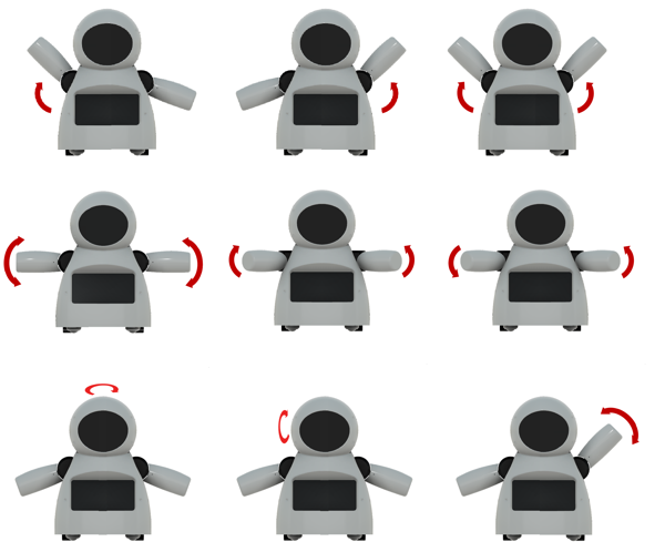
Arduino code is divided in 9 parts:
- RobodaAlegria.ino: this is the main sketch, and it call the other parts. Libraries are imported here. It also define and initialize global variables;
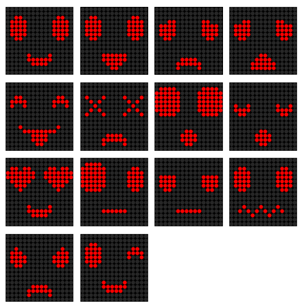
- _05_Def_Olhos.ino: this is where the matrixes for each eye are defined. Each eye is represented by a 8x8 matrix, and 9 options where defined:neutral, wide-eye, closed up, closed down, angry, borred, sad, in love, and dead eyes. There is a different matrix for right and left eyes;
- _06_Def_Boca.ino: this is where the matrices for the mouth are defined. The mouth is represented by a 16x8 matrix, and 9 options where defined:happy, sad, very happy, very sad, neutral, tongue out, open, wide-open, and disgusted mouth;
- _10_Bracos.ino: predefined movements for arms and neck are defined in this file. Nine movements, mov1() to mov9(), were configured;
- _12_Rosto.ino: in this file there are some functions for updating the face of the robot, combining the matrixes defined in _05_Def_Olhos.ino and _06_Def_Boca.ino;
- _13_Motores_DC: it defines the functions for ther DC motors;
- _20_Comunicacao.ino: a function for sending data to ESP8266 is defined in this file;
- _80_Setup.ino: it runs on Arduino power up. It set the inicial face and position of the motors of the robot. It also send commands for the connection to a given Wi-Fi network;
- _90_Loop: main loop. It looks for incoming commands from ESP8266 and call specific functions to control the outputs.
Download Arduino code. Replace the XXXXX by your wifi router SSID and YYYYY by router password on on '_80_Setup.ino'. Please check the baudrate of you ESP8266 and set it properly in the code ('_80_Setup.ino'). Connect the Arduino board to your computer USB port and upload the code.
RoboAlegria.rar
Step 16:Android Apps
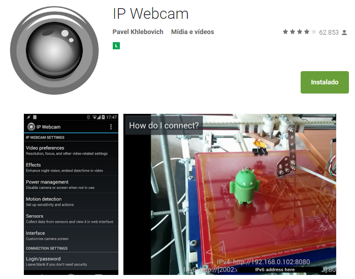
An Android smartphone was used to broadcast the video and audio from the robot to the control interface. You can find the app I used on Google Play store (https://play.google.com/store/apps/details?id=com.pas.webcam).
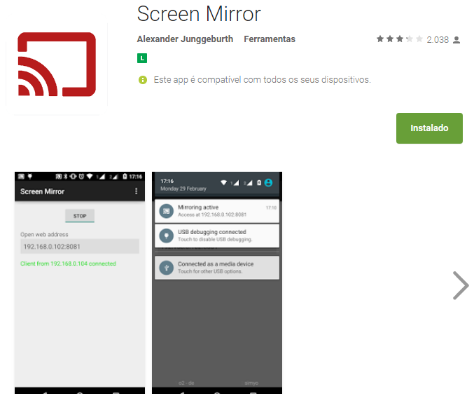
The screen of the smartphone may also be transmited to the control interface, so that the operator can see what's on the screen. You can also find the app I used to mirror the screnn on Google Play store (https://play.google.com/store/apps/details?id=com.ajungg.screenmirror).
An Android video game was also designed to interact with the robot. It's not yet very stable, so it isn't available for download.
Step 17:Control Interface
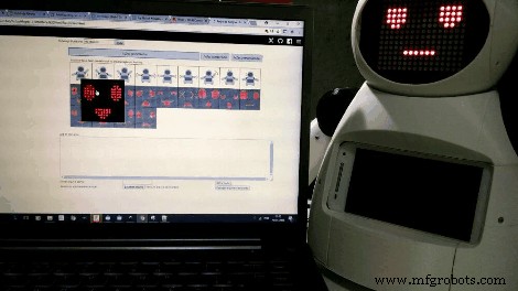


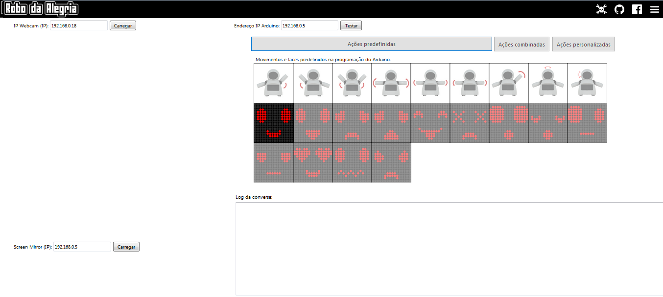
A html interface was designed for the control of the robot.Download interface.rar and extract all the files to a given folder. Then open it on Firefox. The interface is divided in two blocks. To the left there are displays for the camera and screen mirror. To the right there are controll buttons for the commands.
Textbox forms are used in that interface to enter IP address of the ESP8266 module ('Endereço IP Arduino:'), video/audio server from Android IP Webcam app ('IP Webcam (IP):') and Screen Mirror IP address ('Screen Mirror (IP):').
Under 'Ações predefinidas' tab user can select between 9 predefined body movements and 13 different faces. On 'Ações personalizadas' tab user can set a given angles for each of the 6 servos, and individually select between 9 eyes possibilities and 8 mouths variations. A javascript function runs whenever one of those buttons is clicked, and a message is sent for ESP8266's IP address.
Keyboard arrow keys are used for moving the robot forward or backward, and to rotate left or right.
When the interface is started, a warning is displayed, asking if the user wants to share the microphone. If this option is selected, sound intensity of the microphone will be used to send a preconfigured command to the robot. This command will trigger an animation, simulating speech movement on robot's face. A settings button on upper right corner might be used to set the sensitivity of the microphone.
This settings menu might also be used to configure the speed of arms and neck movements.
interface.rar
Step 18:Have Fun
Power it up and have fun!
If you like it, please share this tutorial with you friends! And don't forget to vote on Instructubles Contests! :D
http://www.instructables.com/id/Joy-Robot-Rob%C3%B4-Da-Alegria-Open-Source-3D-Printed-A/
コード
- Arduinoコード
- HTML Interface
Arduino CodeArduino
プレビューなし(ダウンロードのみ)。
HTML InterfaceHTML
プレビューなし(ダウンロードのみ)。
Github
https://github.com/wayoda/LedControlhttps://github.com/wayoda/LedControlGithub
https://github.com/adafruit/Adafruit-PWM-Servo-Driver-Libraryhttps://github.com/adafruit/Adafruit-PWM-Servo-Driver-Library カスタムパーツとエンクロージャー
Thingiverse
https://www.thingiverse.com/thing:2765192CAD file on thingiverse.comYoumagine
https://www.youmagine.com/designs/joy-robot-robo-da-alegria 回路図
製造プロセス