


HC-05 Bluetooth、NRF24L01、およびHC-12トランシーバモジュールを使用したArduinoロボットカーのワイヤレス制御
このチュートリアルでは、前のビデオで作成したArduinoロボットカーをワイヤレスで制御する方法を学習します。 HC-05 Bluetoothモジュール、NRF24L01トランシーバーモジュール、HC-12長距離ワイヤレスモジュール、およびスマートフォンとカスタムメイドのAndroidアプリケーションを使用した、3つの異なるワイヤレス制御方法を紹介します。詳細については、次のビデオを見るか、以下のチュートリアルを読むことができます。
これらの各モジュールをArduinoボードに接続して使用する方法についてのチュートリアルはすでにあるので、詳細が必要な場合はいつでも確認できます。それぞれへのリンクは、以下の記事にあります。
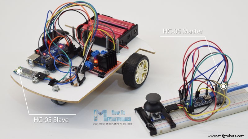
Bluetooth通信から始めます。そのためには、マスターデバイスとスレーブデバイスとして構成する必要がある2つのHC-05Bluetoothモジュールが必要です。
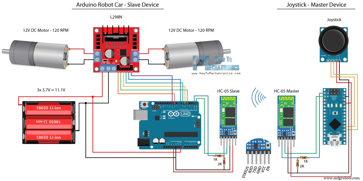
ATコマンドを使用することで簡単にそれを行うことができ、ジョイスティックをマスターに設定し、Arduinoロボットカーをスレーブに設定しました。この例の完全な回路図は次のとおりです。
この例に必要なコンポーネントは、以下のリンクから入手できます。
前のチュートリアルと同じコードを使用します。ここでは、ジョイスティックを使用してArduinoロボットカーを直接制御し、いくつかの変更を加えます。
HC-05マスターコード:
マスターデバイスまたはジョイスティックのコードは非常に単純です。ジョイスティックのX値とY値を読み取るだけで、実際にモーターの速度が調整され、シリアルポートを介してスレーブHC-05Bluetoothデバイスに送信されます。ここで、0から1023までのジョイスティックのアナログ値は、4で割ることにより、0から255までの値に変換されることに注意してください。
これを行うのは、0〜255の範囲を、Bluetoothデバイスを介して、反対側またはArduinoロボットカーで受け入れやすい1バイトとして送信できるためです。
したがって、ここでは、シリアルが2バイトのX値とY値を受け取った場合、Serial.read()関数を使用して、両方を読み取ります。
ここで、値を0〜1023の範囲に戻す必要があります。これは、前のビデオでどのように機能するかをすでに説明した、以下のモーター制御コードに適しています。
コードをアップロードするときは、ArduinoボードのRXピンとTXピンを切断する必要があることに注意してください。
完全なHC-05スレーブコード:
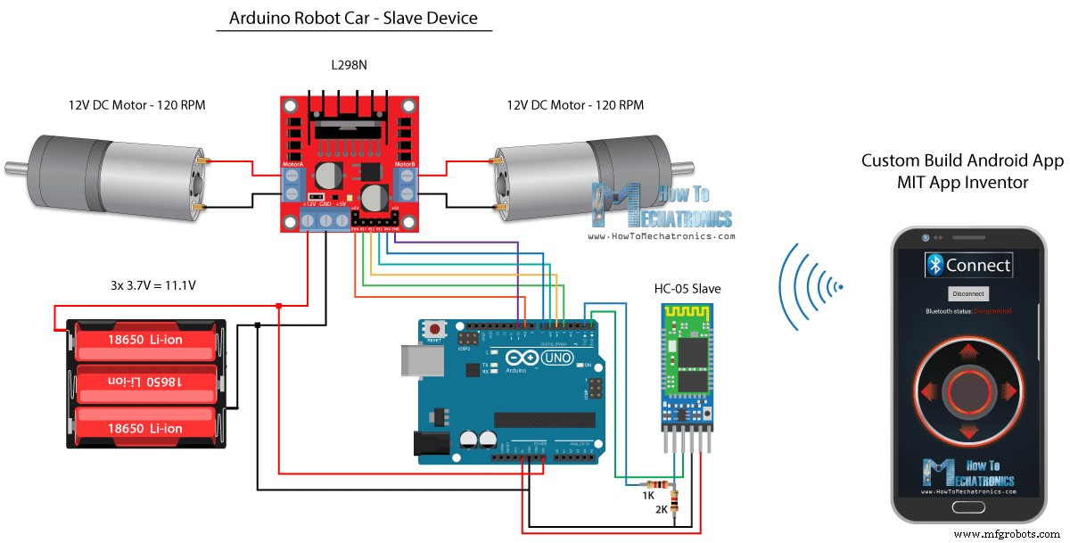
次に、カスタムビルドのAndroidアプリを使用してArduinoロボットカーを制御する方法を見てみましょう。ロボットカーの回路図は前の例とまったく同じですが、HC-05Bluetoothモードがスレーブデバイスとして設定されています。
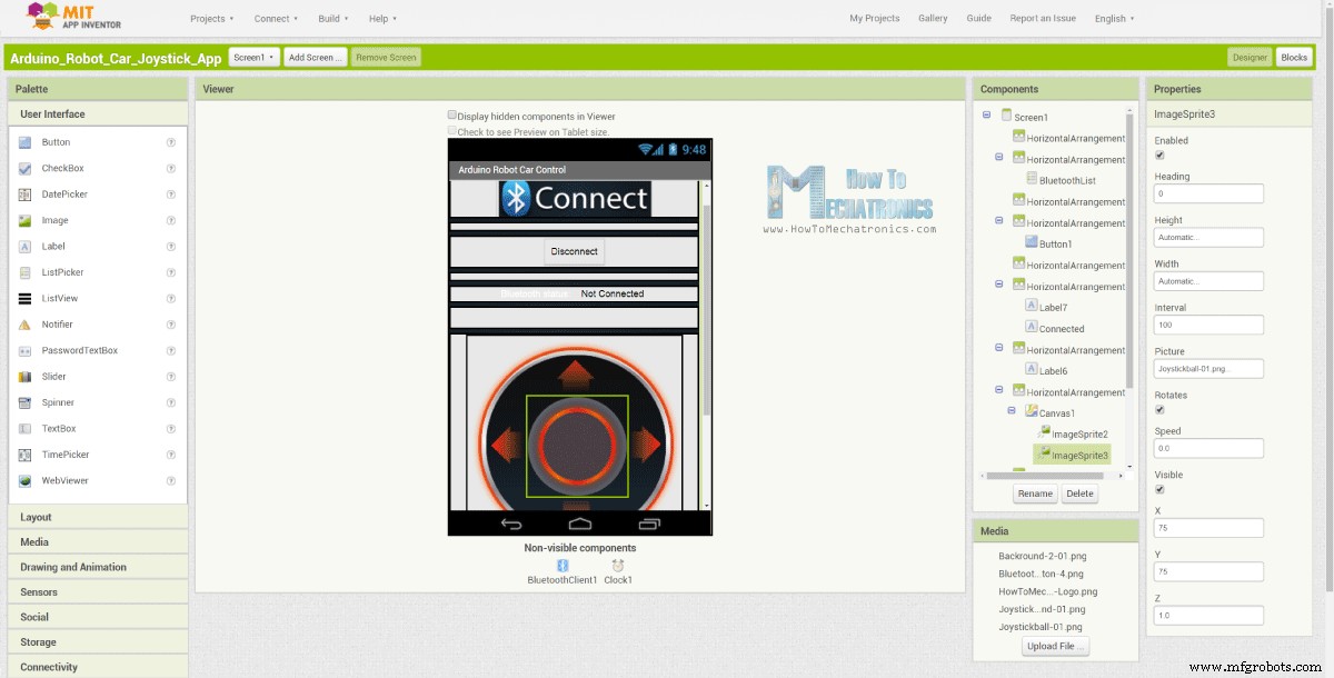
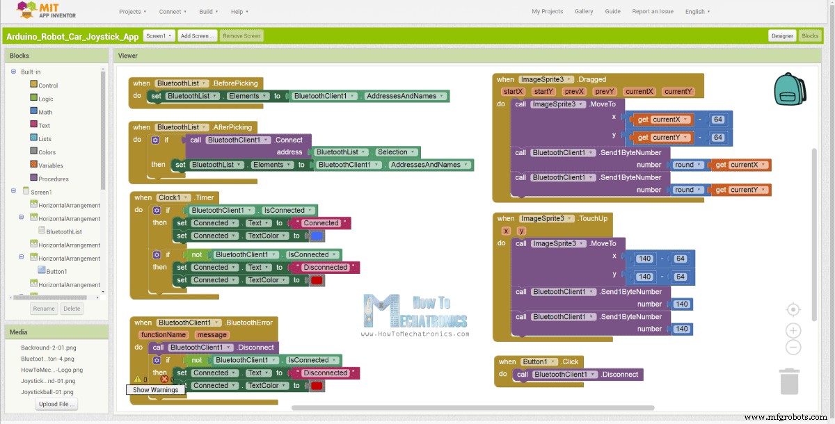
一方、MIT App Inventorオンラインアプリケーションを使用して、独自のAndroidアプリを作成します。その外観は次のとおりです。
つまり、基本的にアプリはジョイスティックをシミュレートします。ジョイスティックの外観は2つの画像、つまり画像のスプライトで構成されています。
このアプリのブロックを見ると、ジョイスティックスプライトをドラッグすると、ジョイスティックボールの画像が現在の指の位置に移動し、同時にXとYが送信されていることがわかります。 Bluetooth経由でArduino車への値。
これらの値は、Serial.read関数を使用して、前の例と同じ方法でArduinoによって受け入れられます。
ここでさらに行う必要があるのは、スマートフォンから受信したX値とY値を、以下のモーター制御コードに適した0〜1023の範囲に変換することです。これらの値はキャンバスのサイズによって異なり、アプリから取得したX値とY値は60から220で、map()関数を使用して簡単に変換できました。
アプリケーションブロックでは、画像スプライトをタッチアップすると、ジョイスティックボールがキャンバスの中央に戻り、移動を停止するために適切な値が車に送信されることもわかります。このアプリは、ウェブサイトの記事と、ジョイスティックの2つの画像で見つけてダウンロードできるため、独自に作成したり、このアプリを変更したりできます。
以下のAndroidアプリと、ジョイスティックの2つの画像をダウンロードできます。
完全なArduinoコード:
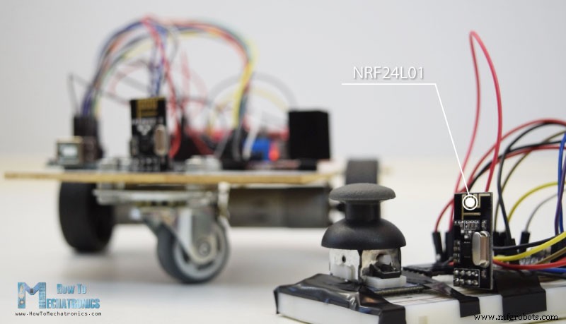
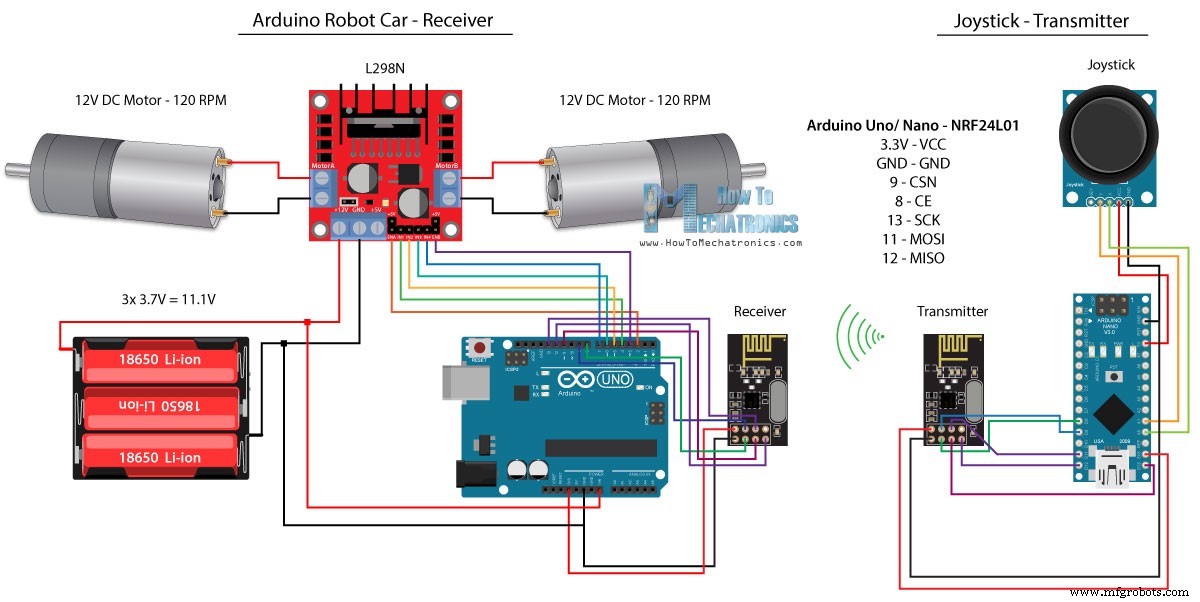
これで、次の方法であるNRF24L01トランシーバモジュールを使用したArduinoロボットカーのワイヤレス制御に進むことができます。
これが回路図です。これらのモジュールはSPI通信を使用しているため、前の例と比較して、L298NドライバーのEnableAピンとEnableBピンをArduinoボードのピン番号2と3に移動しました。NRF24L01を入手できます。次のAmazonリンクのモジュール。
この例では、RF24ライブラリをインストールする必要があります。前の例と同様に、いくつかのピンを定義し、モジュールを送信機として設定した後、ジョイスティックのX値とY値を読み取り、Arduinoロボットカーの他のNRF24L01モジュールに送信します。
まず、アナログ読み取り値は文字列であり、string.toCharArray()関数を使用して文字配列に入れられることに注意してください。次に、radio.write()関数を使用して、その文字配列データを他のモジュールに送信します。
送信機コード:
反対側。 Arduinoロボットカーでは、モジュールをレシーバーとして定義した後、radio.read()関数を使用してデータを受け入れます。次に、atoi()関数を使用して、受信したデータ、またはジョイスティックからのX値とY値を、以下のモーター制御コードに適した整数値に変換します。
とても簡単ですが、もちろん、すでに述べたように、モジュールの接続とセットアップの方法の詳細が必要な場合は、いつでも私の特定のチュートリアルで確認できます。
受信者コード:
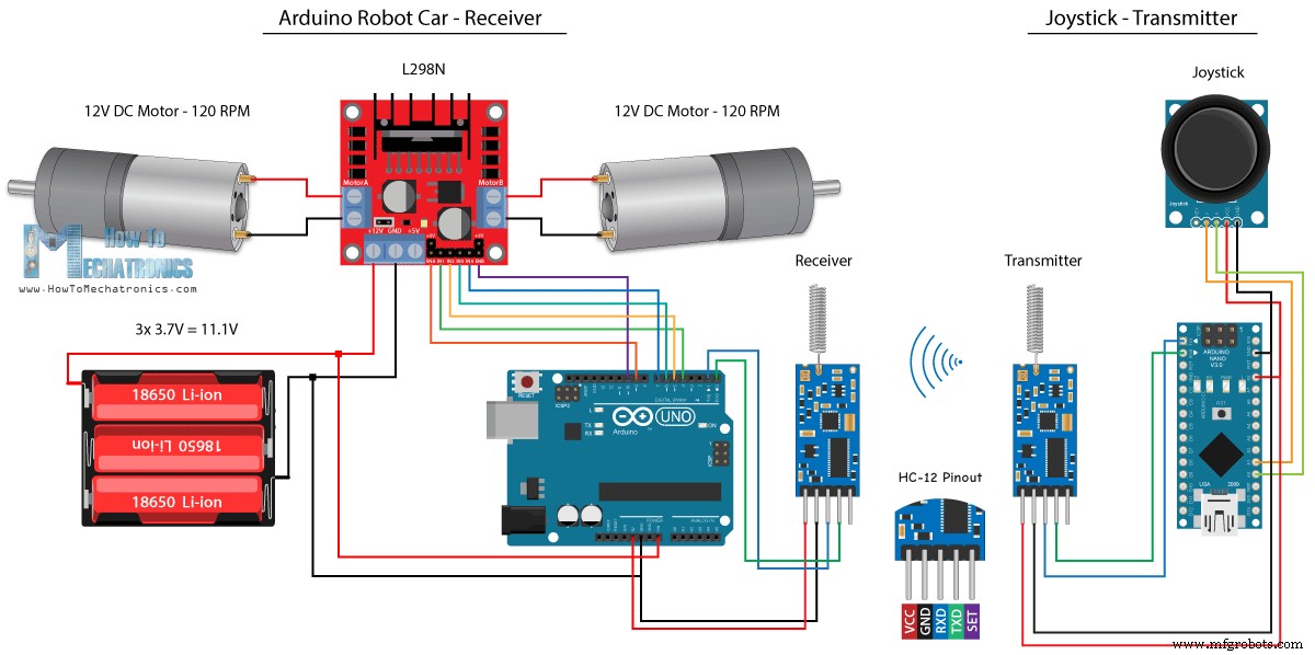
Arduinoロボットカーのワイヤレス制御の最後の方法として、HC-12長距離トランシーバーモジュールを使用します。これらのモジュールは、最大1.8kmの距離で相互に通信できます。
この例の回路図は、シリアルポートを介したArduinoとの通信に同じ方法を使用しているため、HC-05Bluetoothモジュールの回路図とほぼ同じです。
HC-12トランシーバモジュールは、次のAmazonリンクで入手できます。
ジョイスティックのコードは、Bluetooth通信のコードとまったく同じです。ジョイスティックのアナログ値を読み取り、Serial.write()関数を使用して他のモジュールに送信します。
送信機コード:
一方、while()ループでは、データが到着するまで待ってから、Serial.read()関数を使用してデータを読み取り、以下のモーター制御コードに適した0〜1023の範囲に変換し直します。
受信者コード:
これで、このチュートリアルのほとんどすべてが完了しました。以下のコメントセクションでお気軽に質問してください。HC-05Bluetoothモジュールを使用したArduinoロボットカーコントロール
/*
   Arduino Robot Car Wireless Control using the HC-05 Bluetooth

                == MASTER DEVICE - Joystick ==

   by Dejan Nedelkovski, www.HowToMechatronics.com
*/

int xAxis, yAxis;

void setup() {
  Serial.begin(38400); // Default communication rate of the Bluetooth module
}

void loop() {
  xAxis = analogRead(A0); // Read Joysticks X-axis
  yAxis = analogRead(A1); // Read Joysticks Y-axis

  // Send the values via the serial port to the slave HC-05 Bluetooth device
  Serial.write(xAxis/4); // Dividing by 4 for converting from 0 - 1023 to 0 - 256, (1 byte) range
  Serial.write(yAxis/4);
  delay(20);
}Code language: Arduino (arduino)// Code from the Arduino Robot Car
// Read the incoming data from the Joystick, or the master Bluetooth device
while (Serial.available() >= 2) {
x = Serial.read();
delay(10);
y = Serial.read();
}Code language: Arduino (arduino)// Code from the Arduino Robot Car
// Convert back the 0 - 255 range to 0 - 1023, suitable for motor control code below
xAxis = x*4;
yAxis = y*4;Code language: Arduino (arduino)/*
Arduino Robot Car Wireless Control using the HC-05 Bluetooth
== SLAVE DEVICE - Arduino robot car ==
by Dejan Nedelkovski, www.HowToMechatronics.com
*/
#define enA 9
#define in1 4
#define in2 5
#define enB 10
#define in3 6
#define in4 7
int xAxis, yAxis;
unsigned int x = 0;
unsigned int y = 0;
int motorSpeedA = 0;
int motorSpeedB = 0;
void setup() {
pinMode(enA, OUTPUT);
pinMode(enB, OUTPUT);
pinMode(in1, OUTPUT);
pinMode(in2, OUTPUT);
pinMode(in3, OUTPUT);
pinMode(in4, OUTPUT);
Serial.begin(38400); // Default communication rate of the Bluetooth module
}
void loop() {
// Default value - no movement when the Joystick stays in the center
x = 510 / 4;
y = 510 / 4;
// Read the incoming data from the Joystick, or the master Bluetooth device
while (Serial.available() >= 2) {
x = Serial.read();
delay(10);
y = Serial.read();
}
delay(10);
// Convert back the 0 - 255 range to 0 - 1023, suitable for motor control code below
xAxis = x*4;
yAxis = y*4;
// Y-axis used for forward and backward control
if (yAxis < 470) {
// Set Motor A backward
digitalWrite(in1, HIGH);
digitalWrite(in2, LOW);
// Set Motor B backward
digitalWrite(in3, HIGH);
digitalWrite(in4, LOW);
// Convert the declining Y-axis readings for going backward from 470 to 0 into 0 to 255 value for the PWM signal for increasing the motor speed
motorSpeedA = map(yAxis, 470, 0, 0, 255);
motorSpeedB = map(yAxis, 470, 0, 0, 255);
}
else if (yAxis > 550) {
// Set Motor A forward
digitalWrite(in1, LOW);
digitalWrite(in2, HIGH);
// Set Motor B forward
digitalWrite(in3, LOW);
digitalWrite(in4, HIGH);
// Convert the increasing Y-axis readings for going forward from 550 to 1023 into 0 to 255 value for the PWM signal for increasing the motor speed
motorSpeedA = map(yAxis, 550, 1023, 0, 255);
motorSpeedB = map(yAxis, 550, 1023, 0, 255);
}
// If joystick stays in middle the motors are not moving
else {
motorSpeedA = 0;
motorSpeedB = 0;
}
// X-axis used for left and right control
if (xAxis < 470) {
// Convert the declining X-axis readings from 470 to 0 into increasing 0 to 255 value
int xMapped = map(xAxis, 470, 0, 0, 255);
// Move to left - decrease left motor speed, increase right motor speed
motorSpeedA = motorSpeedA - xMapped;
motorSpeedB = motorSpeedB + xMapped;
// Confine the range from 0 to 255
if (motorSpeedA < 0) {
motorSpeedA = 0;
}
if (motorSpeedB > 255) {
motorSpeedB = 255;
}
}
if (xAxis > 550) {
// Convert the increasing X-axis readings from 550 to 1023 into 0 to 255 value
int xMapped = map(xAxis, 550, 1023, 0, 255);
// Move right - decrease right motor speed, increase left motor speed
motorSpeedA = motorSpeedA + xMapped;
motorSpeedB = motorSpeedB - xMapped;
// Confine the range from 0 to 255
if (motorSpeedA > 255) {
motorSpeedA = 255;
}
if (motorSpeedB < 0) {
motorSpeedB = 0;
}
}
// Prevent buzzing at low speeds (Adjust according to your motors. My motors couldn't start moving if PWM value was below value of 70)
if (motorSpeedA < 70) {
motorSpeedA = 0;
}
if (motorSpeedB < 70) {
motorSpeedB = 0;
}
analogWrite(enA, motorSpeedA); // Send PWM signal to motor A
analogWrite(enB, motorSpeedB); // Send PWM signal to motor B
}Code language: Arduino (arduino)スマートフォンとカスタムビルドのAndroidアプリを使用したArduinoロボットカーコントロール
// Read the incoming data from the Smartphone Android App
  while (Serial.available() >= 2) {
    x = Serial.read();
    delay(10);
    y = Serial.read();
}Code language: Arduino (arduino)// Makes sure we receive corrent values
if (x > 60 & x < 220) {
xAxis = map(x, 220, 60, 1023, 0); // Convert the smartphone X and Y values to 0 - 1023 range, suitable motor for the motor control code below
}
if (y > 60 & y < 220) {
yAxis = map(y, 220, 60, 0, 1023);
}Code language: Arduino (arduino)
Arduino_Robot_Car_Joystick_App.apk
1ファイル Arduino_Robot_Car_Joystick_App_aia_file
1ファイル ジョイスティックアプリの画像
1ファイル/*
Arduino Robot Car Wireless Control using the HC-05 Bluetooth and custom-build Android app
== SLAVE DEVICE - Arduino robot car ==
by Dejan Nedelkovski, www.HowToMechatronics.com
*/
#define enA 9
#define in1 4
#define in2 5
#define enB 10
#define in3 6
#define in4 7
int xAxis, yAxis;
int x = 0;
int y = 0;
int motorSpeedA = 0;
int motorSpeedB = 0;
void setup() {
pinMode(enA, OUTPUT);
pinMode(enB, OUTPUT);
pinMode(in1, OUTPUT);
pinMode(in2, OUTPUT);
pinMode(in3, OUTPUT);
pinMode(in4, OUTPUT);
Serial.begin(38400); // Default communication rate of the Bluetooth module
}
void loop() {
// Default value - no movement when the Joystick stays in the center
xAxis = 510;
yAxis = 510;
// Read the incoming data from the Smartphone Android App
while (Serial.available() >= 2) {
x = Serial.read();
delay(10);
y = Serial.read();
}
delay(10);
// Makes sure we receive corrent values
if (x > 60 & x < 220) {
xAxis = map(x, 220, 60, 1023, 0); // Convert the smartphone X and Y values to 0 - 1023 range, suitable motor for the motor control code below
}
if (y > 60 & y < 220) {
yAxis = map(y, 220, 60, 0, 1023);
}
// Y-axis used for forward and backward control
if (yAxis < 470) {
// Set Motor A backward
digitalWrite(in1, HIGH);
digitalWrite(in2, LOW);
// Set Motor B backward
digitalWrite(in3, HIGH);
digitalWrite(in4, LOW);
// Convert the declining Y-axis readings for going backward from 470 to 0 into 0 to 255 value for the PWM signal for increasing the motor speed
motorSpeedA = map(yAxis, 470, 0, 0, 255);
motorSpeedB = map(yAxis, 470, 0, 0, 255);
}
else if (yAxis > 550) {
// Set Motor A forward
digitalWrite(in1, LOW);
digitalWrite(in2, HIGH);
// Set Motor B forward
digitalWrite(in3, LOW);
digitalWrite(in4, HIGH);
// Convert the increasing Y-axis readings for going forward from 550 to 1023 into 0 to 255 value for the PWM signal for increasing the motor speed
motorSpeedA = map(yAxis, 550, 1023, 0, 255);
motorSpeedB = map(yAxis, 550, 1023, 0, 255);
}
// If joystick stays in middle the motors are not moving
else {
motorSpeedA = 0;
motorSpeedB = 0;
}
// X-axis used for left and right control
if (xAxis < 470) {
// Convert the declining X-axis readings from 470 to 0 into increasing 0 to 255 value
int xMapped = map(xAxis, 470, 0, 0, 255);
// Move to left - decrease left motor speed, increase right motor speed
motorSpeedA = motorSpeedA - xMapped;
motorSpeedB = motorSpeedB + xMapped;
// Confine the range from 0 to 255
if (motorSpeedA < 0) {
motorSpeedA = 0;
}
if (motorSpeedB > 255) {
motorSpeedB = 255;
}
}
if (xAxis > 550) {
// Convert the increasing X-axis readings from 550 to 1023 into 0 to 255 value
int xMapped = map(xAxis, 550, 1023, 0, 255);
// Move right - decrease right motor speed, increase left motor speed
motorSpeedA = motorSpeedA + xMapped;
motorSpeedB = motorSpeedB - xMapped;
// Confine the range from 0 to 255
if (motorSpeedA > 255) {
motorSpeedA = 255;
}
if (motorSpeedB < 0) {
motorSpeedB = 0;
}
}
// Prevent buzzing at low speeds (Adjust according to your motors. My motors couldn't start moving if PWM value was below value of 70)
if (motorSpeedA < 70) {
motorSpeedA = 0;
}
if (motorSpeedB < 70) {
motorSpeedB = 0;
}
analogWrite(enA, motorSpeedA); // Send PWM signal to motor A
analogWrite(enB, motorSpeedB); // Send PWM signal to motor B
}Code language: Arduino (arduino)NRF24L01トランシーバモジュールを使用したArduinoロボットカーのワイヤレス制御
/*
   Arduino Robot Car Wireless Control using the NRF24L01 Transceiver module

             == Transmitter - Joystick ==

   by Dejan Nedelkovski, www.HowToMechatronics.com

   Library: TMRh20/RF24, https://github.com/tmrh20/RF24/
*/

#include <SPI.h>
#include <nRF24L01.h>
#include <RF24.h>

RF24 radio(8, 9); // CE, CSN
const byte address[6] = "00001";

char xyData[32] = "";
String xAxis, yAxis;

void setup() {
  Serial.begin(9600);
  radio.begin();
  radio.openWritingPipe(address);
  radio.setPALevel(RF24_PA_MIN);
  radio.stopListening();
}

void loop() {

  xAxis = analogRead(A0); // Read Joysticks X-axis
  yAxis = analogRead(A1); // Read Joysticks Y-axis
  // X value
  xAxis.toCharArray(xyData, 5); // Put the String (X Value) into a character array
  radio.write(&xyData, sizeof(xyData)); // Send the array data (X value) to the other NRF24L01 modile
  // Y value
  yAxis.toCharArray(xyData, 5);
  radio.write(&xyData, sizeof(xyData));
  delay(20);
}Code language: Arduino (arduino)// Code from the Arduino Robot Car - NRF24L01 example
if (radio.available()) { // If the NRF240L01 module received data
radio.read(&receivedData, sizeof(receivedData)); // Read the data and put it into character array
xAxis = atoi(&receivedData[0]); // Convert the data from the character array (received X value) into integer
delay(10);
radio.read(&receivedData, sizeof(receivedData));
yAxis = atoi(&receivedData[0]);
delay(10);
}Code language: Arduino (arduino)/*
Arduino Robot Car Wireless Control using the NRF24L01 Transceiver module
== Receiver - Arduino robot car ==
by Dejan Nedelkovski, www.HowToMechatronics.com
Library: TMRh20/RF24, https://github.com/tmrh20/RF24/
*/
#include <SPI.h>
#include <nRF24L01.h>
#include <RF24.h>
#define enA 2 // Note: Pin 9 in previous video ( pin 10 is used for the SPI communication of the NRF24L01)
#define in1 4
#define in2 5
#define enB 3 // Note: Pin 10 in previous video
#define in3 6
#define in4 7
RF24 radio(8, 9); // CE, CSN
const byte address[6] = "00001";
char receivedData[32] = "";
int xAxis, yAxis;
int motorSpeedA = 0;
int motorSpeedB = 0;
void setup() {
pinMode(enA, OUTPUT);
pinMode(enB, OUTPUT);
pinMode(in1, OUTPUT);
pinMode(in2, OUTPUT);
pinMode(in3, OUTPUT);
pinMode(in4, OUTPUT);
Serial.begin(9600);
radio.begin();
radio.openReadingPipe(0, address);
radio.setPALevel(RF24_PA_MIN);
radio.startListening();
}
void loop() {
if (radio.available()) { // If the NRF240L01 module received data
radio.read(&receivedData, sizeof(receivedData)); // Read the data and put it into character array
xAxis = atoi(&receivedData[0]); // Convert the data from the character array (received X value) into integer
delay(10);
radio.read(&receivedData, sizeof(receivedData));
yAxis = atoi(&receivedData[0]);
delay(10);
}
// Y-axis used for forward and backward control
if (yAxis < 470) {
// Set Motor A backward
digitalWrite(in1, HIGH);
digitalWrite(in2, LOW);
// Set Motor B backward
digitalWrite(in3, HIGH);
digitalWrite(in4, LOW);
// Convert the declining Y-axis readings for going backward from 470 to 0 into 0 to 255 value for the PWM signal for increasing the motor speed
motorSpeedA = map(yAxis, 470, 0, 0, 255);
motorSpeedB = map(yAxis, 470, 0, 0, 255);
}
else if (yAxis > 550) {
// Set Motor A forward
digitalWrite(in1, LOW);
digitalWrite(in2, HIGH);
// Set Motor B forward
digitalWrite(in3, LOW);
digitalWrite(in4, HIGH);
// Convert the increasing Y-axis readings for going forward from 550 to 1023 into 0 to 255 value for the PWM signal for increasing the motor speed
motorSpeedA = map(yAxis, 550, 1023, 0, 255);
motorSpeedB = map(yAxis, 550, 1023, 0, 255);
}
// If joystick stays in middle the motors are not moving
else {
motorSpeedA = 0;
motorSpeedB = 0;
}
// X-axis used for left and right control
if (xAxis < 470) {
// Convert the declining X-axis readings from 470 to 0 into increasing 0 to 255 value
int xMapped = map(xAxis, 470, 0, 0, 255);
// Move to left - decrease left motor speed, increase right motor speed
motorSpeedA = motorSpeedA - xMapped;
motorSpeedB = motorSpeedB + xMapped;
// Confine the range from 0 to 255
if (motorSpeedA < 0) {
motorSpeedA = 0;
}
if (motorSpeedB > 255) {
motorSpeedB = 255;
}
}
if (xAxis > 550) {
// Convert the increasing X-axis readings from 550 to 1023 into 0 to 255 value
int xMapped = map(xAxis, 550, 1023, 0, 255);
// Move right - decrease right motor speed, increase left motor speed
motorSpeedA = motorSpeedA + xMapped;
motorSpeedB = motorSpeedB - xMapped;
// Confine the range from 0 to 255
if (motorSpeedA > 255) {
motorSpeedA = 255;
}
if (motorSpeedB < 0) {
motorSpeedB = 0;
}
}
// Prevent buzzing at low speeds (Adjust according to your motors. My motors couldn't start moving if PWM value was below value of 70)
if (motorSpeedA < 70) {
motorSpeedA = 0;
}
if (motorSpeedB < 70) {
motorSpeedB = 0;
}
analogWrite(enA, motorSpeedA); // Send PWM signal to motor A
analogWrite(enB, motorSpeedB); // Send PWM signal to motor B
}Code language: Arduino (arduino)HC-12長距離トランシーバーを使用したArduinoロボットカーのワイヤレス制御
/*
   Arduino Robot Car Wireless Control using the HC-12 long range wireless module

                == Transmitter - Joystick ==

   by Dejan Nedelkovski, www.HowToMechatronics.com
*/

int xAxis, yAxis;

void setup() {
  Serial.begin(9600); // Default communication rate of the Bluetooth module
}

void loop() {
  xAxis = analogRead(A0); // Read Joysticks X-axis
  yAxis = analogRead(A1); // Read Joysticks Y-axis

  // Send the values via the serial port to the slave HC-05 Bluetooth device
  Serial.write(xAxis/4); // Dividing by 4 for converting from 0 - 1023 to 0 - 256, (1 byte) range
  Serial.write(yAxis/4);
  delay(20);
}Code language: Arduino (arduino)/*
Arduino Robot Car Wireless Control using the HC-12 long range wireless module
== Receiver - Arduino robot car ==
by Dejan Nedelkovski, www.HowToMechatronics.com
*/
#define enA 9
#define in1 4
#define in2 5
#define enB 10
#define in3 6
#define in4 7
int xAxis, yAxis;
int x = 0;
int y = 0;
int motorSpeedA = 0;
int motorSpeedB = 0;
void setup() {
pinMode(enA, OUTPUT);
pinMode(enB, OUTPUT);
pinMode(in1, OUTPUT);
pinMode(in2, OUTPUT);
pinMode(in3, OUTPUT);
pinMode(in4, OUTPUT);
Serial.begin(9600); // Default communication rate of the Bluetooth module
}
void loop() {
// Default value - no movement when the Joystick stays in the center
xAxis = 510;
yAxis = 510;
// Read the incoming data from the
while (Serial.available() == 0) {}
x = Serial.read();
delay(10);
y = Serial.read();
delay(10);
// Convert back the 0 - 255 range to 0 - 1023, suitable for motor control code below
xAxis = x * 4;
yAxis = y * 4;
// Y-axis used for forward and backward control
if (yAxis < 470) {
// Set Motor A backward
digitalWrite(in1, HIGH);
digitalWrite(in2, LOW);
// Set Motor B backward
digitalWrite(in3, HIGH);
digitalWrite(in4, LOW);
// Convert the declining Y-axis readings for going backward from 470 to 0 into 0 to 255 value for the PWM signal for increasing the motor speed
motorSpeedA = map(yAxis, 470, 0, 0, 255);
motorSpeedB = map(yAxis, 470, 0, 0, 255);
}
else if (yAxis > 550) {
// Set Motor A forward
digitalWrite(in1, LOW);
digitalWrite(in2, HIGH);
// Set Motor B forward
digitalWrite(in3, LOW);
digitalWrite(in4, HIGH);
// Convert the increasing Y-axis readings for going forward from 550 to 1023 into 0 to 255 value for the PWM signal for increasing the motor speed
motorSpeedA = map(yAxis, 550, 1023, 0, 255);
motorSpeedB = map(yAxis, 550, 1023, 0, 255);
}
// If joystick stays in middle the motors are not moving
else {
motorSpeedA = 0;
motorSpeedB = 0;
}
// X-axis used for left and right control
if (xAxis < 470) {
// Convert the declining X-axis readings from 470 to 0 into increasing 0 to 255 value
int xMapped = map(xAxis, 470, 0, 0, 255);
// Move to left - decrease left motor speed, increase right motor speed
motorSpeedA = motorSpeedA - xMapped;
motorSpeedB = motorSpeedB + xMapped;
// Confine the range from 0 to 255
if (motorSpeedA < 0) {
motorSpeedA = 0;
}
if (motorSpeedB > 255) {
motorSpeedB = 255;
}
}
if (xAxis > 550) {
// Convert the increasing X-axis readings from 550 to 1023 into 0 to 255 value
int xMapped = map(xAxis, 550, 1023, 0, 255);
// Move right - decrease right motor speed, increase left motor speed
motorSpeedA = motorSpeedA + xMapped;
motorSpeedB = motorSpeedB - xMapped;
// Confine the range from 0 to 255
if (motorSpeedA > 255) {
motorSpeedA = 255;
}
if (motorSpeedB < 0) {
motorSpeedB = 0;
}
}
// Prevent buzzing at low speeds (Adjust according to your motors. My motors couldn't start moving if PWM value was below value of 70)
if (motorSpeedA < 70) {
motorSpeedA = 0;
}
if (motorSpeedB < 70) {
motorSpeedB = 0;
}
analogWrite(enA, motorSpeedA); // Send PWM signal to motor A
analogWrite(enB, motorSpeedB); // Send PWM signal to motor B
}Code language: Arduino (arduino)
製造プロセス
- Bluetoothで制御されるRaspberryPi Robot
- Arduino、1Sheeld、Androidを使用したユニバーサルリモコン
- Arduinoとスマートフォンを使用したDIY電圧計
- LEDを制御するBluetoothを搭載したArduino!
- FirmataとXboxOneControllerを使用してArduinoRoverを制御する
- Arduino +処理+ PHPを使用したカーカウンター
- AlexaとArduinoIoTCloudを使用したテレビのフルコントロール
- ArduinoとRDA8057Mを使用したFMラジオ
- BLUE_P:ワイヤレスArduinoプログラミングシールド
- ArduinoUnoとBluetoothによる車の制御
- 手の動きとArduinoを使用した素晴らしいコントロールコンピュータ