


SLA と FDM:一般的な 3D プリント技術の比較
アディティブ マニュファクチャリング、特に最新の 3D プリントは、1983 年の最初の開発以来、長い道のりを歩んできました。今日の 3D プリントされた部品は、高い解像度と公差を達成できます。より一般的な 2 つの手法は、ステレオリソグラフィー (SLA) と溶融堆積モデリング (FDM) です。どちらも 1980 年代に登場しましたが、部品の製造方法が明らかに異なるため、最終的な部品はそれぞれ異なる利点をもたらします。
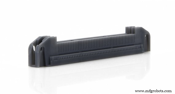 Protolabs の MicroFine Gray™ 樹脂で作られた SLA パーツは、マイクロ精度の分解能を実現します。
 SLA の仕組み
SLAは、その部品の原材料としてフォトポリマー樹脂を使用しています。フォトポリマーは硬化するためにレーザーからの強力な紫外線を必要とし、それが SLA の背後にある中心的な考え方です。ビルドは樹脂に沈められたプラットフォームで行われます。レーザーがタンクの上に置かれ、精密なミラーに向けられて、液体樹脂を融合させ、一度に 1 層ずつ目的の部品形状を実現するために硬化させます。サポート構造は最初に作成される層であり、パーツがプラットフォームにしっかりと固定され、適切にサポートされるようにします。各パスで、リコーター ブレードが部品上の樹脂の表面張力を壊します。パーツはボトムアップで構築されます。
FDM の仕組み
3D プリントの最も初期の形式の 1 つである FDM は、Stratasys の創設者の 1 人である Scott Crump によって発明されました。コンセプトはシンプルで、ホットグルーガンを使用するのとよく似ています。プラスチックの熱可塑性フィラメントまたはスプールを融点まで加熱します。高温の液体プラスチックがノズルから出てきて、ビルド プラットフォーム上に X 軸と Y 軸に沿って薄い単層を作成します。層は急速に冷えて固まります。各層が完成すると、プラットフォームが下降し、追加の溶融プラスチックが堆積され、パーツが垂直方向 (Z 軸に沿って) に成長します。
SLA と FDM の材料特性
| プロセス | 仕組み | 強さ | 仕上げ | 共通資料 |
|---|---|---|---|---|
| SLA | レーザー硬化フォトポリマー | 2,500-10,000 (psi) 17.2-68.9 (MPa) | 0.002-0.006 インチ (0.051-0.152 mm) 標準の追加レイヤー | ABS、PC、および PP に類似した熱可塑性樹脂のようなフォトポリマー |
| FDM | 融合した押し出し | 5,200-9,800 (psi) 35.9-67.6 (MPa) | 0.005 ~ 0.013 インチ (0.127 ~ 0.330 mm) 標準の追加レイヤー | ABS、PC、PC/ABS、PPSU、PEEK、ULTEM |
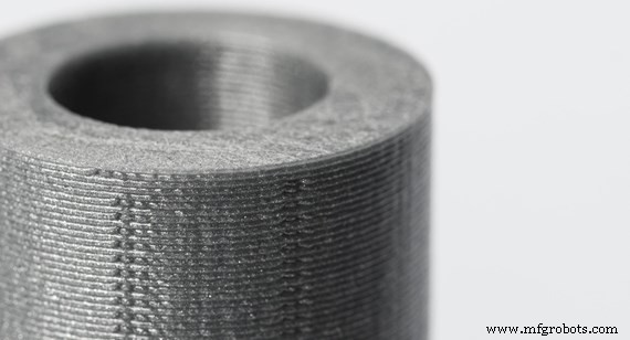 この FDM パーツでは、レイヤー ラインが表示されます。写真:3Dhubs.com
 Neither of these techniques creates parts as strong as ones that are injection molded, for example, but they are suitable for rapid prototyping. SLA’s thin layers and strong bonding between the layers makes its parts smoother, with minimal striations along the Z axis, the direction of the build.
SLA Considerations
If details and surface smoothness are important for your part, SLA handily beats FDM. In part, because of its roots in laser technology, SLA parts can offer incredibly fine detail, yet pricing is competitive. Also, the SLA ultraviolet light curing process avoids FDM’s issues caused by heat compressing previously drawn layers. Equally important, SLA offers many additional finishing options, such as dyeing and texturing.
With SLA, there are three resolution levels from which to choose, ranging from 0.004 in. (0.1016mm) to 0.001 in. (0.0254mm) for layer thickness. Choosing one over the other not only affects part quality, but manufacturing time, too. Minimum feature size can be as small as 0.0025 in. (0.0635mm) on the XY plane and 0.008 in. (0.2032mm) on the Z axis.
One important issue with SLA parts is their sensitivity to light. As photopolymers, they can degrade from exposure to UV rays, such as sunlight. Adding a protective coating can slow this process.
MicroFine™ is an exclusive Protolabs material available in gray and green. This micro-resolution, ABS-like material can print layers that are extremely thin:just 0.001 in. (0.0254mm). That kind of precision is a prerequisite for building parts with many small feature details and is regularly used for small and highly accurate medical components.
FDM Considerations
FDM uses engineering-grade materials (see chart above) and offers a range of color options. With some FDM printers, parts can be as large as 427 in. x 153 in. x 172 in. (10,845.8mm x 3,886.2mm x 4,368.8mm). Essentially it depends on the size of the build space. Also, FDM parts are moderately priced, making it ideal for hobbyists, dental offices, and classrooms.
FDM’s tolerance is dependent on how the machine is set up, but can be as small as +/-0.0035 in. (+/-0.0015mm). Layer thickness varies based on the material you’re using, and some printers can print as thin as 0.001 in. (0.0254mm), although this would lead to long print times and may not be possible with larger parts.
Because temperature affects the core material, FDM parts are subject to rippled exterior edges caused as new layers are dropped atop previous layers. These Z-axis issues also cause weakness in the build. So, a part’s strength is entirely dependent on the direction in which it was built.
FDM does not do well with wide, flat areas, and has difficulties printing sharp corners, so adding fillets to your design makes sense. For all these reasons, prototyping with FDM works well when accuracy and surface finish aren't critical.
Although FDM gets the check for cost, SLA is quite competitive, especially for cosmetic prototypes with intricate designs. It’s also a go-to process to create forms for injection molding and casting.
When to Use SLA and FDM
With all of these considerations in mind, here is a list of when to use either method.
Use SLA :
- For rapid, complex prototyping
- When precision and a smooth surface finish is important
- When high resolution, fine detail, and accuracy is necessary
- For creating molds for casting to facilitate mass production
- When strength and durability of the model is not crucial (models made from resin may suffer when exposed to the sun for long periods)
Use FDM :
- For prototyping
- When a selection of colors is needed
- For low-cost models
- When precision and surface finish aren’t crucial
- For hobbyist and maker projects
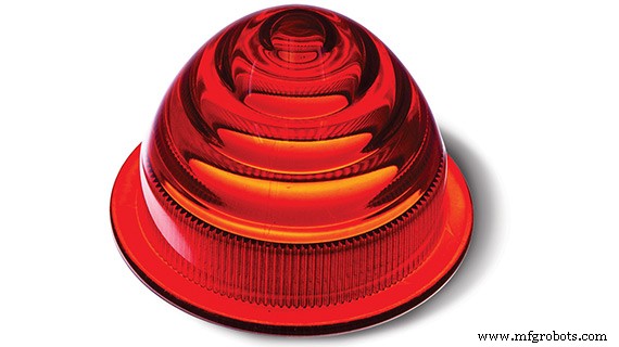
SLA produced this clear, red taillight with a smooth finish and custom post-production painting.
For additional help, feel free to contact a Protolabs applications engineer at 877-479-3680 or ADMIN@MFGROBOTS.COM. To get your next design project started today, simply upload a 3D CAD model for an interactive quote within hours.
産業技術