



MAX30102パルスオキシメーターで心拍数とSpO₂を精密測定 - Arduino対応
コンポーネントと用品
| Arduino UNO | × | 1 |
| Adafruit OLED 128x32 | × | 1 |
| ブザー | × | 1 |
| Maxim Integrated MAX30102 高感度パルスオキシメーター/心拍センサー(ウェアラブルヘルス用) | × | 1 |
このプロジェクトについて
イントロ
こんにちは。このチュートリアルでは、MAX30102パルスオキシメトリー/心拍モニターモジュールをArduino UNOボードとインターフェースし、OLEDディスプレイとブザーを使ってBPM(心拍数)を測定するプロジェクトを作ります。
BPMは「beats per minute(拍動/分)」で、安静時の正常な人は65-75程度、アスリートはこれより低い場合があります。SpO₂は酸素飽和度で、正常な人は95%以上です。
MAX30102は様々なモジュールで販売されています。私はWAVGAT版を持っていますが、ICがMAX30102なら問題ありません。
コンポーネント
使用するもの:


テスト
チュートリアルで使用したコードはかなり明確で、SparkFun_MAX3010xライブラリのサンプルそのものです。
OLEDとブザー用に作ったコードは、「HeartRate」サンプルの改変版で、センサーに指を置くよう促します。

指を置いたら、ブザーの「ビープ」音が心拍と同期するか、OLEDのアニメーションが心拍と同期するまで落ち着いて待ちます。その後、正しいBPMが読み取れます。
注:コードでは平均BPMを表示しています。4回分のBPMの平均を取るため、より正確です。少し時間を置いてください。

OLED用ビットマップの作成
表示される小さなハートはビットマップ画像です。センサーが心拍を検出するたびに、大きなハートのビットマップ画像に切り替えて少し表示することで、ブザーのビープ音と合わせて心臓が鼓動しているような印象を与えます。
コードで後から呼び出す2つのビットマップ:

これらを作るには、表示したいものの画像(黒、白背景)を探します。サイズを忘れずに。私のOLEDは128x32ピクセルで、画像はそれより小さい(32x32ピクセルと24x21ピクセル)です。

LCD Assistantをダウンロードして開きます(以下の手順で)


これで「数値」が得られます:

コードでの呼び出し例:
display.drawBitmap(5, 5, logo2_bmp, 24, 21, WHITE);これは以下を意味します:
display.drawBitmap(開始X座標, 開始Y座標, ビットマップ名, 幅, 高さ, 色);コードでは、指が検出されたときに一つ、心拍が検出されたときにもう一つを呼び出しています。
これで好きなものを作れます。
コード
MAX_BPM_OLED_Buzzer.ino
/* This code works with MAX30102 + 128x32 OLED i2c + Buzzer and Arduino UNO
 * It's displays the Average BPM on the screen, with an animation and a buzzer sound
 * everytime a heart pulse is detected
 * It's a modified version of the HeartRate library example
 * Refer to www.surtrtech.com for more details or SurtrTech YouTube channel */
#include <Adafruit_GFX.h> //OLED libraries
#include <Adafruit_SSD1306.h>
#include <Wire.h>
#include "MAX30105.h" //MAX3010x library
#include "heartRate.h" //Heart rate calculating algorithm

MAX30105 particleSensor;
const byte RATE_SIZE = 4; //Increase this for more averaging. 4 is good.
byte rates[RATE_SIZE]; //Array of heart rates
byte rateSpot = 0;
long lastBeat = 0; //Time at which the last beat occurred
float beatsPerMinute;
int beatAvg;

#define SCREEN_WIDTH 128 // OLED display width, in pixels
#define SCREEN_HEIGHT 32 // OLED display height, in pixels
#define OLED_RESET -1 // Reset pin # (or -1 if sharing Arduino reset pin)
Adafruit_SSD1306 display(SCREEN_WIDTH, SCREEN_HEIGHT, &Wire, OLED_RESET); //Declaring the display name (display)

static const unsigned char PROGMEM logo2_bmp[] = {
  0x03, 0xC0, 0xF0, 0x06, 0x71, 0x8C, 0x0C, 0x1B, 0x06, 0x18, 0x0E, 0x02, 0x10, 0x0C, 0x03, 0x10,
  0x04, 0x01, 0x10, 0x04, 0x01, 0x10, 0x40, 0x01, 0x10, 0x40, 0x01, 0x10, 0xC0, 0x03, 0x08, 0x88,
  0x02, 0x08, 0xB8, 0x04, 0xFF, 0x37, 0x08, 0x01, 0x30, 0x18, 0x01, 0x90, 0x30, 0x00, 0xC0, 0x60,
  0x00, 0x60, 0xC0, 0x00, 0x31, 0x80, 0x00, 0x1B, 0x00, 0x00, 0x0E, 0x00, 0x00, 0x04, 0x00,
};

static const unsigned char PROGMEM logo3_bmp[] = {
  0x01, 0xF0, 0x0F, 0x80, 0x06, 0x1C, 0x38, 0x60, 0x18, 0x06, 0x60, 0x18, 0x10, 0x01, 0x80, 0x08,
  0x20, 0x01, 0x80, 0x04, 0x40, 0x00, 0x00, 0x02, 0x40, 0x00, 0x00, 0x02, 0xC0, 0x00, 0x08, 0x03,
  0x80, 0x00, 0x08, 0x01, 0x80, 0x00, 0x18, 0x01, 0x80, 0x00, 0x1C, 0x01, 0x80, 0x00, 0x14, 0x00,
  0x80, 0x00, 0x14, 0x00, 0x80, 0x00, 0x14, 0x00, 0x40, 0x10, 0x12, 0x00, 0x40, 0x10, 0x12, 0x00,
  0x7E, 0x1F, 0x23, 0xFE, 0x03, 0x31, 0xA0, 0x04, 0x01, 0xA0, 0xA0, 0x0C, 0x00, 0xA0, 0xA0, 0x08,
  0x00, 0x60, 0xE0, 0x10, 0x00, 0x20, 0x60, 0x20, 0x06, 0x00, 0x40, 0x60, 0x03, 0x00, 0x40, 0xC0,
  0x01, 0x80, 0x01, 0x80, 0x00, 0xC0, 0x03, 0x00, 0x00, 0x60, 0x06, 0x00, 0x00, 0x30, 0x0C,
  0x00, 0x00, 0x08, 0x10, 0x00, 0x00, 0x06, 0x60, 0x00, 0x00, 0x03, 0xC0, 0x00, 0x00, 0x01, 0x80,
  0x00
};

void setup() {
  display.begin(SSD1306_SWITCHCAPVCC, 0x3C); //Start the OLED display
  display.display();
  delay(3000);
  // Initialize sensor
  particleSensor.begin(Wire, I2C_SPEED_FAST); //Use default I2C port, 400kHz speed
  particleSensor.setup(); //Configure sensor with default settings
  particleSensor.setPulseAmplitudeRed(0x0A); //Turn Red LED to low to indicate sensor is running
}

void loop() {
  long irValue = particleSensor.getIR(); //Reading the IR value it will permit us to know if there's a finger on the sensor or not
  //Also detecting a heartbeat
  if(irValue > 7000){ //If a finger is detected
    display.clearDisplay(); //Clear the display
    display.drawBitmap(5, 5, logo2_bmp, 24, 21, WHITE); //Draw the first bmp picture (little heart)
    display.setTextSize(2); //Near it display the average BPM you can display the BPM if you want
    display.setTextColor(WHITE);
    display.setCursor(50,0);
    display.println("BPM");
    display.setCursor(50,18);
    display.println(beatAvg);
    display.display();
    if (checkForBeat(irValue) == true) //If a heart beat is detected
    {
      display.clearDisplay(); //Clear the display
      display.drawBitmap(0, 0, logo3_bmp, 32, 32, WHITE); //Draw the second picture (bigger heart)
      display.setTextSize(2); //And still displays the average BPM
      display.setTextColor(WHITE);
      display.setCursor(50,0);
      display.println("BPM");
      display.setCursor(50,18);
      display.println(beatAvg);
      display.display();
      tone(3,1000); //And tone the buzzer for a 100ms you can reduce it it will be better
      delay(100);
      noTone(3); //Deactivate the buzzer to have the effect of a "bip"
      //We sensed a beat!
      long delta = millis() - lastBeat; //Measure duration between two beats
      lastBeat = millis();
      beatsPerMinute = 60 / (delta / 1000.0); //Calculating the BPM
      if (beatsPerMinute < 255 && beatsPerMinute > 20) //To calculate the average we strore some values (4) then do some math to calculate the average
      {
        rates[rateSpot++] = (byte)beatsPerMinute; //Store this reading in the array
        rateSpot %= RATE_SIZE; //Wrap variable
        //Take average of readings
        beatAvg = 0;
        for (byte x = 0 ; x < RATE_SIZE ; x++)
          beatAvg += rates[x];
        beatAvg /= RATE_SIZE;
      }
    }
  }
  if (irValue < 7000){ //If no finger is detected it inform the user and put the average BPM to 0 or it will be stored for the next measure
    beatAvg=0;
    display.clearDisplay();
    display.setTextSize(1);
    display.setTextColor(WHITE);
    display.setCursor(30,5);
    display.println("Please Place ");
    display.setCursor(30,15);
    display.println("your finger ");
    display.display();
    noTone(3);
  }
}
使用ライブラリ
回路図
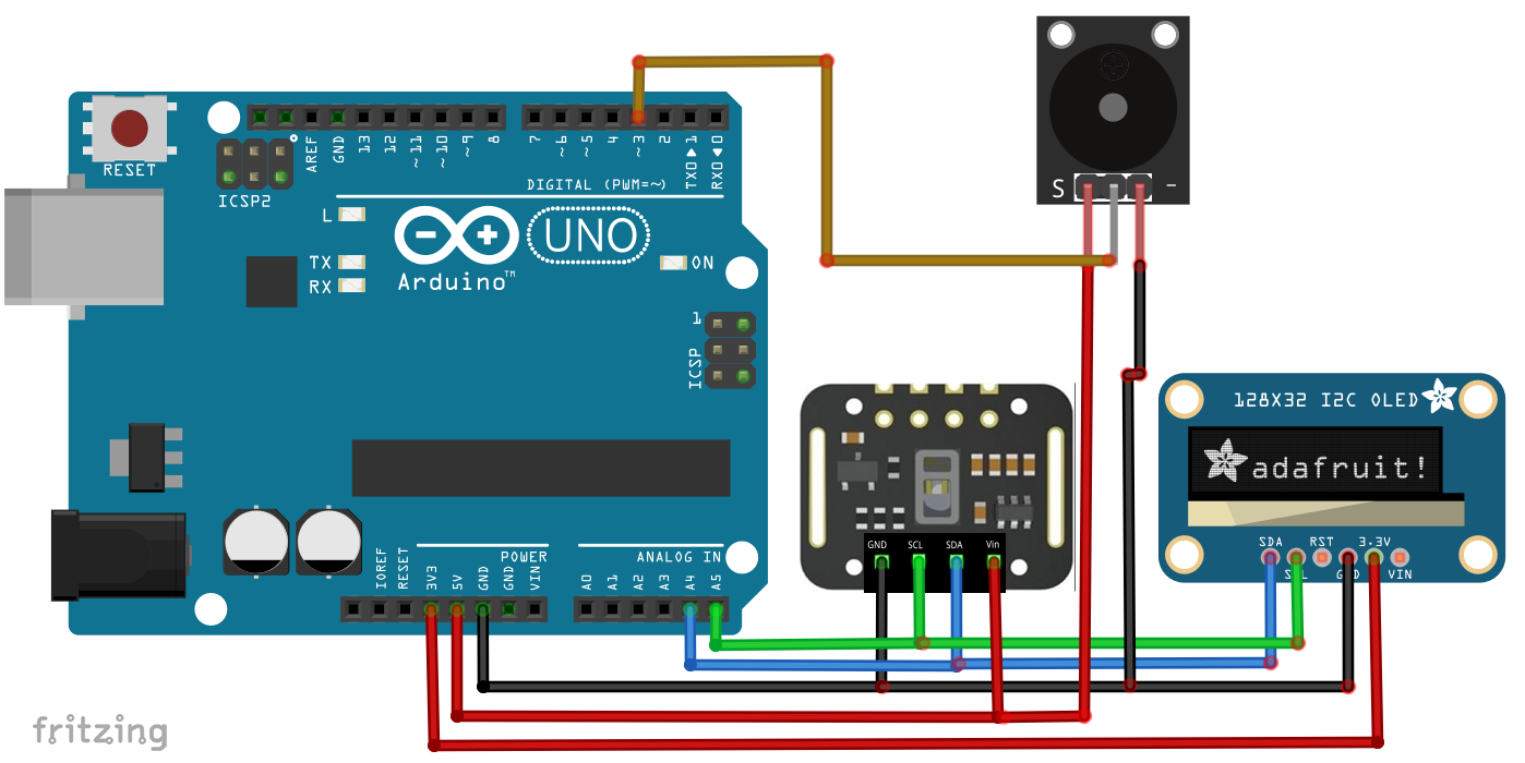
両モジュールともI²Cインターフェース。2ピンブザーの場合、(-)をGND、(+)を抵抗経由でD3に接続
製造プロセス
- QR・RFID・体温検知統合アクセス制御システム(Raspberry Piベース)
- 複数DS18B20 1-WireセンサーをRaspberry Pi接続で精密温度監視
- Raspberry Piと湿度センサーで作る自動エアロポニックスシステム
- リモート心拍数監視システム:AWS IoTアラート付き
- Raspberry Pi と Python でロボットを構築:完全ガイド
- Arduino Portenta H7にMAX6675でサーモカップル温度センサーを接続する
- Arduino NanoとMPU-6050で作るリアルタイムジャイロスコープゲーム
- ArduinoとMAX30100で作るリアルタイムIoT心拍数モニター
- フォトレジスタとArduinoで作る高精度心拍数モニター
- 銅メッキプロジェクト:Arduino UNOで作るスマート電気メッキシステム
- Visual Components、Matterport、ProFeeder X自動化でワークショップスペースを最大活用