


ArduinoとMPU6050加速度計とジャイロスコープのチュートリアル
このチュートリアルでは、ArduinoでMPU6050加速度計とジャイロスコープセンサーを使用する方法を学習します。最初に、MPU6050がどのように機能し、そこからデータを読み取る方法を説明し、次に2つの実用的な例を示します。
次のビデオを見るか、以下のチュートリアルを読むことができます。
最初の例では、Processing開発環境を使用して、センサーの向きを3Dで視覚化し、2番目の例では、単純な自己安定化プラットフォームまたはDIYジンバルを作成します。 MPU6050の向きと、その融合した加速度計とジャイロスコープのデータに基づいて、プラットフォームを水平に保つ3つのサーボを制御します。
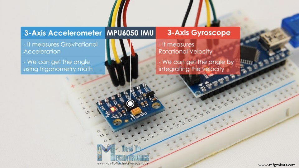
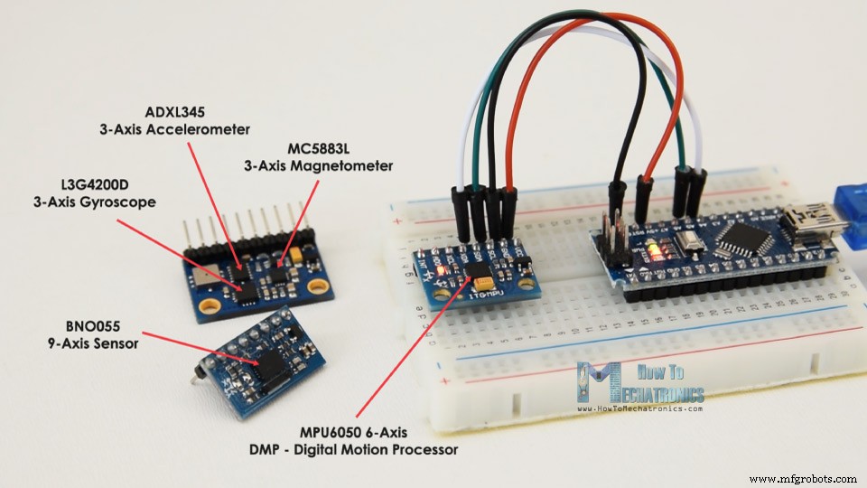
MPU6050 IMUには、3軸加速度計と3軸ジャイロスコープの両方が1つのチップに統合されています。
ジャイロスコープは、X、Y、Z軸に沿って、回転速度または角位置の経時変化率を測定します。測定にはMEMSテクノロジーとコリオリ効果を使用していますが、詳細については、私の特定のMEMSセンサーの仕組みのチュートリアルを確認してください。ジャイロスコープの出力は1秒あたりの度数であるため、角度位置を取得するには、角速度を積分する必要があります。
一方、MPU6050加速度計は、ADXL345加速度センサーの前のビデオで説明したのと同じ方法で加速度を測定します。簡単に言うと、3つの軸に沿った重力加速度を測定でき、三角法の計算を使用して、センサーが配置されている角度を計算できます。したがって、加速度計とジャイロスコープのデータを融合または組み合わせると、センサーの向きに関する非常に正確な情報を取得できます。
MPU6050 IMUは、6つの出力、または3つの加速度計出力と3つのジャイロスコープ出力があるため、6軸モーショントラッキングデバイスまたは6 DoF(6自由度)デバイスとも呼ばれます。
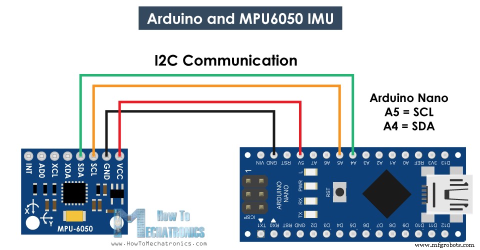
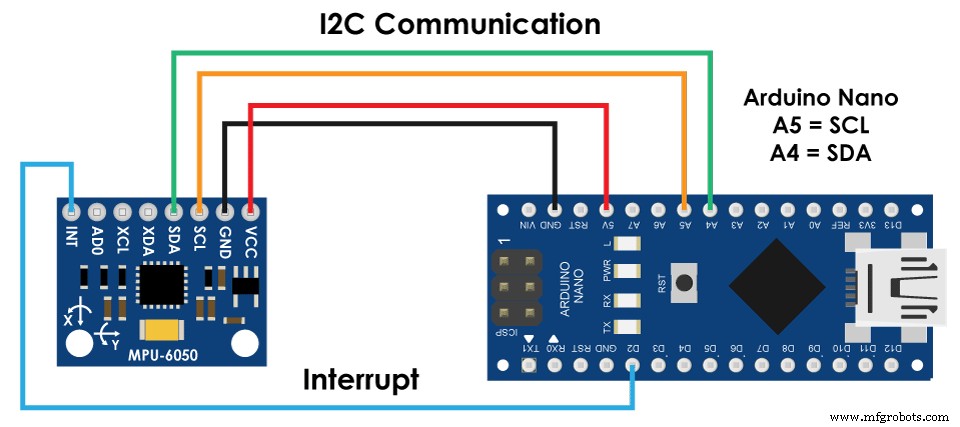
Arduinoを使用してMPU6050センサーからデータを接続して読み取る方法を見てみましょう。 Arduinoとの通信にはI2Cプロトコルを使用しているため、Arduinoを接続するために必要なのは2本のワイヤーと、電源を供給するための2本のワイヤーだけです。
このArduinoチュートリアルに必要なコンポーネントは、以下のリンクから入手できます。
MPU6050センサーからデータを読み取るためのArduinoコードは次のとおりです。コードの下に、その詳細な説明があります。
コードの説明: したがって、最初に、I2C通信に使用されるWire.hライブラリを含め、データの保存に必要ないくつかの変数を定義する必要があります。
セットアップセクションでは、ワイヤライブラリを初期化し、電力管理レジスタを介してセンサーをリセットする必要があります。そのためには、レジスタアドレスを確認できるセンサーのデータシートを確認する必要があります。
また、必要に応じて、構成レジスタを使用して、加速度計とジャイロスコープのフルスケール範囲を選択できます。この例では、加速度計にデフォルトの±2gの範囲を使用し、ジャイロスコープに250度/秒の範囲を使用するため、コードのこの部分はコメントのままにしておきます。
ループセクションでは、加速度計のデータを読み取ることから始めます。各軸のデータは2バイトまたはレジスタに格納されており、センサーのデータシートからこれらのレジスタのアドレスを確認できます。
それらすべてを読み取るために、最初のレジスタから開始し、requiestFrom()関数を使用して、X、Y、およびZ軸の6つのレジスタすべてを読み取るように要求します。次に、各レジスタからデータを読み取ります。出力は2の補数であるため、適切に組み合わせて正しい値を取得します。
角度の計算に適した-1gから+1gの出力値を取得するために、出力を以前に選択した感度で除算します。
最後に、これら2つの式を使用して、加速度計のデータからロール角とピッチ角を計算します。
次に、同じ方法を使用して、ジャイロスコープのデータを取得します。
6つのジャイロスコープレジスタを読み取り、それらのデータを適切に結合し、以前に選択した感度で除算して、1秒あたりの度数で出力を取得します。
ここで、いくつかの小さな計算されたエラー値を使用して出力値を修正していることに気付くことができます。これについては、すぐに取得する方法を説明します。したがって、出力は1秒あたりの度数であるため、度を取得するには、それらに時間を掛ける必要があります。時間値は、millis()関数を使用して各読み取り反復の前にキャプチャされます。
最後に、補完的なフィルターを使用して、加速度計とジャイロスコープのデータを融合します。ここでは、ジャイロスコープのデータの96%を取得しています。これは、非常に正確で、外力の影響を受けないためです。ジャイロスコープの欠点は、ドリフトしたり、時間が経つにつれて出力にエラーが発生したりすることです。したがって、長期的には、加速度計からのデータ(この場合は4%)を使用して、ジャイロスコープのドリフトエラーを排除するのに十分です。
ただし、加速度計のデータからヨーを計算できないため、補完的なフィルターを実装することはできません。
結果を確認する前に、エラー訂正値を取得する方法について簡単に説明します。これらのエラーを計算するために、センサーがフラットな静止位置にあるときに、calculate_IMU_error()カスタム関数を呼び出すことができます。ここでは、すべての出力に対して200の読み取りを行い、それらを合計して200で除算します。センサーを平らな静止位置に保持しているため、期待される出力値は0になります。したがって、この計算により、センサーの平均誤差を取得できます。作る。
シリアルモニターに値を印刷するだけで、値がわかったら、ロールとピッチの両方の計算、および3つのジャイロスコープ出力に対して、前に示したコードに値を実装できます。
最後に、Serial.print関数を使用して、ロール、ピッチ、ヨーの値をシリアルモニターに印刷し、センサーが正しく機能するかどうかを確認できます。
次に、3D視覚化の例を作成するには、ArduinoがProcessing開発環境のシリアルポートを介して送信しているこのデータを受け入れる必要があります。完全な処理コードは次のとおりです。
ここでは、Arduinoからの受信データを読み取り、それを適切なRoll、Pitch、およびYaw変数に入れます。メインの描画ループでは、これらの値を使用して3Dオブジェクトを回転させます。この場合は、特定の色とテキストが表示された単純なボックスです。
スケッチを実行すると、MPU6050センサーが方向を追跡するのにどれほど優れているかがわかります。 3Dオブジェクトは、センサーの向きを非常に正確に追跡し、応答性も非常に高くなっています。
先に述べたように、唯一の欠点は、ヨーが補完フィルターを使用できないため、時間の経過とともにドリフトすることです。これを改善するには、追加のセンサーを使用する必要があります。これは通常、ジャイロスコープのヨードリフトの長期補正として使用できる磁力計です。ただし、MPU6050には実際には、データのオンボード計算に使用されるデジタルモーションプロセッサと呼ばれる機能があり、ヨードリフトを排除することができます。
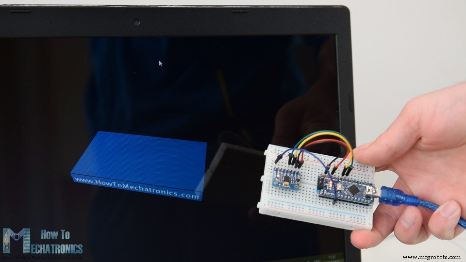
これは、デジタルモーションプロセッサを使用した同じ3Dの例です。ヨードリフトがなくても、方向追跡がどれほど正確であるかがわかります。オンボードプロセッサは、オブジェクトの方向と回転を3次元で表すために使用されるクォータニオンを計算して出力することもできます。この例では、実際には、オイラー角を使用するときに発生するジンバルロックの影響を受けない方向を表すためにクォータニオンを使用しています。
それでも、センサーからこのデータを取得することは、前に説明したものよりも少し複雑です。まず、Arduinoデジタルピンに接続して追加のワイヤを接続する必要があります。これは、MPU6050からこのデータタイプを読み取るために使用される割り込みピンです。
コードも少し複雑なので、JeffRowbergによるi2cdevlibライブラリを使用します。このライブラリはGitHubからダウンロードでき、ウェブサイトの記事にへのリンクを含めます。
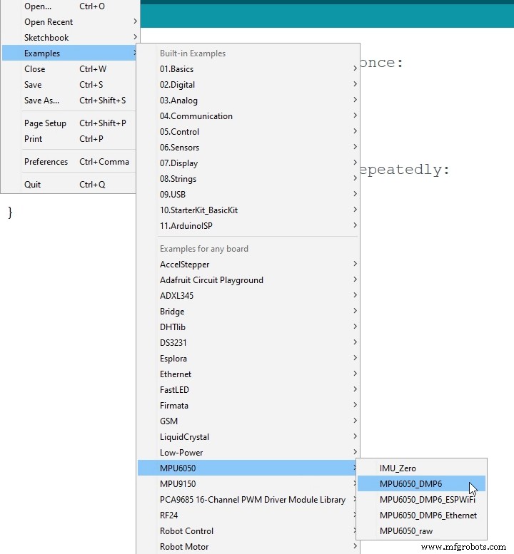
ライブラリをインストールしたら、ライブラリからMPU6050_DMP6の例を開くことができます。この例は、各行のコメントでよく説明されています。
ここでは、必要な出力の種類、クォータニオン、オイラー角、ヨー、ピッチアンドロール、加速度値、または3Dビジュアライゼーションのクォータニオンを選択できます。このライブラリには、3D視覚化の例の処理スケッチも含まれています。前の例のようにボックスの形状を取得するように変更しました。選択した「OUTPUT_TEAPOT」出力に対して、MPU6050_DPM6の例で機能する3D視覚化処理コードを次に示します。
したがって、ここではserialEvent()関数を使用して、Arduinoからのクォータニオンを受け取り、メインの描画ループでそれらを使用して3Dオブジェクトを回転させます。スケッチを実行すると、オブジェクトを3次元で回転させるのにクォータニオンがどれほど優れているかがわかります。
このチュートリアルを過負荷にしないために、2番目の例であるDIYArduinoジンバルまたは自己安定化プラットフォームを別の記事に配置しました。
以下のコメントセクションで、このチュートリアルに関連する質問をしてください。また、Arduinoプロジェクトのコレクションを確認することを忘れないでください。概要
ArduinoとMPU6050
MPU6050Arduinoコード
/*
   Arduino and MPU6050 Accelerometer and Gyroscope Sensor Tutorial
   by Dejan, https://howtomechatronics.com
*/
#include <Wire.h>
const int MPU = 0x68; // MPU6050 I2C address
float AccX, AccY, AccZ;
float GyroX, GyroY, GyroZ;
float accAngleX, accAngleY, gyroAngleX, gyroAngleY, gyroAngleZ;
float roll, pitch, yaw;
float AccErrorX, AccErrorY, GyroErrorX, GyroErrorY, GyroErrorZ;
float elapsedTime, currentTime, previousTime;
int c = 0;
void setup() {
  Serial.begin(19200);
  Wire.begin();                      // Initialize comunication
  Wire.beginTransmission(MPU);       // Start communication with MPU6050 // MPU=0x68
  Wire.write(0x6B);                  // Talk to the register 6B
  Wire.write(0x00);                  // Make reset - place a 0 into the 6B register
  Wire.endTransmission(true);        //end the transmission
  /*
  // Configure Accelerometer Sensitivity - Full Scale Range (default +/- 2g)
  Wire.beginTransmission(MPU);
  Wire.write(0x1C);                  //Talk to the ACCEL_CONFIG register (1C hex)
  Wire.write(0x10);                  //Set the register bits as 00010000 (+/- 8g full scale range)
  Wire.endTransmission(true);
  // Configure Gyro Sensitivity - Full Scale Range (default +/- 250deg/s)
  Wire.beginTransmission(MPU);
  Wire.write(0x1B);                   // Talk to the GYRO_CONFIG register (1B hex)
  Wire.write(0x10);                   // Set the register bits as 00010000 (1000deg/s full scale)
  Wire.endTransmission(true);
  delay(20);
  */
  // Call this function if you need to get the IMU error values for your module
  calculate_IMU_error();
  delay(20);
}
void loop() {
  // === Read acceleromter data === //
  Wire.beginTransmission(MPU);
  Wire.write(0x3B); // Start with register 0x3B (ACCEL_XOUT_H)
  Wire.endTransmission(false);
  Wire.requestFrom(MPU, 6, true); // Read 6 registers total, each axis value is stored in 2 registers
  //For a range of +-2g, we need to divide the raw values by 16384, according to the datasheet
  AccX = (Wire.read() << 8 | Wire.read()) / 16384.0; // X-axis value
  AccY = (Wire.read() << 8 | Wire.read()) / 16384.0; // Y-axis value
  AccZ = (Wire.read() << 8 | Wire.read()) / 16384.0; // Z-axis value
  // Calculating Roll and Pitch from the accelerometer data
  accAngleX = (atan(AccY / sqrt(pow(AccX, 2) + pow(AccZ, 2))) * 180 / PI) - 0.58; // AccErrorX ~(0.58) See the calculate_IMU_error()custom function for more details
  accAngleY = (atan(-1 * AccX / sqrt(pow(AccY, 2) + pow(AccZ, 2))) * 180 / PI) + 1.58; // AccErrorY ~(-1.58)
  // === Read gyroscope data === //
  previousTime = currentTime;        // Previous time is stored before the actual time read
  currentTime = millis();            // Current time actual time read
  elapsedTime = (currentTime - previousTime) / 1000; // Divide by 1000 to get seconds
  Wire.beginTransmission(MPU);
  Wire.write(0x43); // Gyro data first register address 0x43
  Wire.endTransmission(false);
  Wire.requestFrom(MPU, 6, true); // Read 4 registers total, each axis value is stored in 2 registers
  GyroX = (Wire.read() << 8 | Wire.read()) / 131.0; // For a 250deg/s range we have to divide first the raw value by 131.0, according to the datasheet
  GyroY = (Wire.read() << 8 | Wire.read()) / 131.0;
  GyroZ = (Wire.read() << 8 | Wire.read()) / 131.0;
  // Correct the outputs with the calculated error values
  GyroX = GyroX + 0.56; // GyroErrorX ~(-0.56)
  GyroY = GyroY - 2; // GyroErrorY ~(2)
  GyroZ = GyroZ + 0.79; // GyroErrorZ ~ (-0.8)
  // Currently the raw values are in degrees per seconds, deg/s, so we need to multiply by sendonds (s) to get the angle in degrees
  gyroAngleX = gyroAngleX + GyroX * elapsedTime; // deg/s * s = deg
  gyroAngleY = gyroAngleY + GyroY * elapsedTime;
  yaw =  yaw + GyroZ * elapsedTime;
  // Complementary filter - combine acceleromter and gyro angle values
  roll = 0.96 * gyroAngleX + 0.04 * accAngleX;
  pitch = 0.96 * gyroAngleY + 0.04 * accAngleY;

  // Print the values on the serial monitor
  Serial.print(roll);
  Serial.print("/");
  Serial.print(pitch);
  Serial.print("/");
  Serial.println(yaw);
}
void calculate_IMU_error() {
  // We can call this funtion in the setup section to calculate the accelerometer and gyro data error. From here we will get the error values used in the above equations printed on the Serial Monitor.
  // Note that we should place the IMU flat in order to get the proper values, so that we then can the correct values
  // Read accelerometer values 200 times
  while (c < 200) {
    Wire.beginTransmission(MPU);
    Wire.write(0x3B);
    Wire.endTransmission(false);
    Wire.requestFrom(MPU, 6, true);
    AccX = (Wire.read() << 8 | Wire.read()) / 16384.0 ;
    AccY = (Wire.read() << 8 | Wire.read()) / 16384.0 ;
    AccZ = (Wire.read() << 8 | Wire.read()) / 16384.0 ;
    // Sum all readings
    AccErrorX = AccErrorX + ((atan((AccY) / sqrt(pow((AccX), 2) + pow((AccZ), 2))) * 180 / PI));
    AccErrorY = AccErrorY + ((atan(-1 * (AccX) / sqrt(pow((AccY), 2) + pow((AccZ), 2))) * 180 / PI));
    c++;
  }
  //Divide the sum by 200 to get the error value
  AccErrorX = AccErrorX / 200;
  AccErrorY = AccErrorY / 200;
  c = 0;
  // Read gyro values 200 times
  while (c < 200) {
    Wire.beginTransmission(MPU);
    Wire.write(0x43);
    Wire.endTransmission(false);
    Wire.requestFrom(MPU, 6, true);
    GyroX = Wire.read() << 8 | Wire.read();
    GyroY = Wire.read() << 8 | Wire.read();
    GyroZ = Wire.read() << 8 | Wire.read();
    // Sum all readings
    GyroErrorX = GyroErrorX + (GyroX / 131.0);
    GyroErrorY = GyroErrorY + (GyroY / 131.0);
    GyroErrorZ = GyroErrorZ + (GyroZ / 131.0);
    c++;
  }
  //Divide the sum by 200 to get the error value
  GyroErrorX = GyroErrorX / 200;
  GyroErrorY = GyroErrorY / 200;
  GyroErrorZ = GyroErrorZ / 200;
  // Print the error values on the Serial Monitor
  Serial.print("AccErrorX: ");
  Serial.println(AccErrorX);
  Serial.print("AccErrorY: ");
  Serial.println(AccErrorY);
  Serial.print("GyroErrorX: ");
  Serial.println(GyroErrorX);
  Serial.print("GyroErrorY: ");
  Serial.println(GyroErrorY);
  Serial.print("GyroErrorZ: ");
  Serial.println(GyroErrorZ);
}Code language: Arduino (arduino)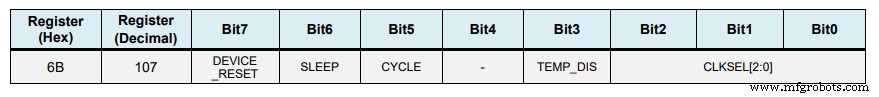
// Configure Accelerometer Sensitivity - Full Scale Range (default +/- 2g)
  Wire.beginTransmission(MPU);
  Wire.write(0x1C);                  //Talk to the ACCEL_CONFIG register (1C hex)
  Wire.write(0x10);                  //Set the register bits as 00010000 (+/- 8g full scale range)
  Wire.endTransmission(true);
  // Configure Gyro Sensitivity - Full Scale Range (default +/- 250deg/s)
  Wire.beginTransmission(MPU);
  Wire.write(0x1B);                   // Talk to the GYRO_CONFIG register (1B hex)
  Wire.write(0x10);                   // Set the register bits as 00010000 (1000deg/s full scale)
  Wire.endTransmission(true);
  */Code language: Arduino (arduino)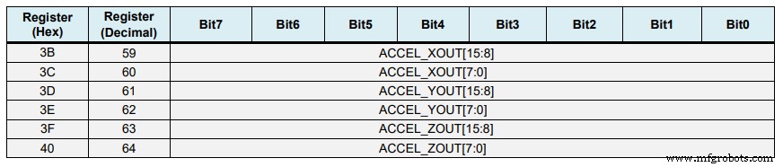
// === Read acceleromter data === //
  Wire.beginTransmission(MPU);
  Wire.write(0x3B); // Start with register 0x3B (ACCEL_XOUT_H)
  Wire.endTransmission(false);
  Wire.requestFrom(MPU, 6, true); // Read 6 registers total, each axis value is stored in 2 registers
  //For a range of +-2g, we need to divide the raw values by 16384, according to the datasheet
  AccX = (Wire.read() << 8 | Wire.read()) / 16384.0; // X-axis value
  AccY = (Wire.read() << 8 | Wire.read()) / 16384.0; // Y-axis value
  AccZ = (Wire.read() << 8 | Wire.read()) / 16384.0; // Z-axis valueCode language: Arduino (arduino)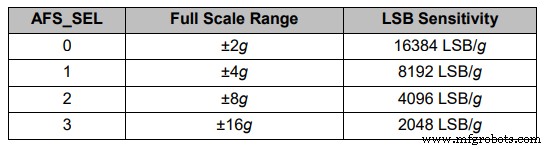
// Calculating Roll and Pitch from the accelerometer data
  accAngleX = (atan(AccY / sqrt(pow(AccX, 2) + pow(AccZ, 2))) * 180 / PI) - 0.58; // AccErrorX ~(0.58) See the calculate_IMU_error()custom function for more details
  accAngleY = (atan(-1 * AccX / sqrt(pow(AccY, 2) + pow(AccZ, 2))) * 180 / PI) + 1.58; // AccErrorY ~(-1.58)Code language: Arduino (arduino)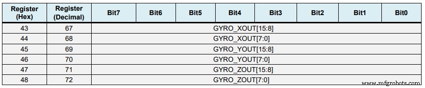
// === Read gyroscope data === //
  previousTime = currentTime;        // Previous time is stored before the actual time read
  currentTime = millis();            // Current time actual time read
  elapsedTime = (currentTime - previousTime) / 1000; // Divide by 1000 to get seconds
  Wire.beginTransmission(MPU);
  Wire.write(0x43); // Gyro data first register address 0x43
  Wire.endTransmission(false);
  Wire.requestFrom(MPU, 6, true); // Read 4 registers total, each axis value is stored in 2 registers
  GyroX = (Wire.read() << 8 | Wire.read()) / 131.0; // For a 250deg/s range we have to divide first the raw value by 131.0, according to the datasheet
  GyroY = (Wire.read() << 8 | Wire.read()) / 131.0;
  GyroZ = (Wire.read() << 8 | Wire.read()) / 131.0;Code language: Arduino (arduino)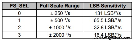
// Correct the outputs with the calculated error values
  GyroX = GyroX + 0.56; // GyroErrorX ~(-0.56)
  GyroY = GyroY - 2; // GyroErrorY ~(2)
  GyroZ = GyroZ + 0.79; // GyroErrorZ ~ (-0.8)
  // Currently the raw values are in degrees per seconds, deg/s, so we need to multiply by sendonds (s) to get the angle in degrees
  gyroAngleX = gyroAngleX + GyroX * elapsedTime; // deg/s * s = deg
  gyroAngleY = gyroAngleY + GyroY * elapsedTime;
yaw = yaw + GyroZ * elapsedTime;Code language: Arduino (arduino)// Complementary filter - combine acceleromter and gyro angle values
roll = 0.96 * gyroAngleX + 0.04 * accAngleX;
pitch = 0.96 * gyroAngleY + 0.04 * accAngleY;Code language: Arduino (arduino)void calculate_IMU_error() {
// We can call this funtion in the setup section to calculate the accelerometer and gyro data error. From here we will get the error values used in the above equations printed on the Serial Monitor.
// Note that we should place the IMU flat in order to get the proper values, so that we then can the correct values
// Read accelerometer values 200 times
while (c < 200) {
Wire.beginTransmission(MPU);
Wire.write(0x3B);
Wire.endTransmission(false);
Wire.requestFrom(MPU, 6, true);
AccX = (Wire.read() << 8 | Wire.read()) / 16384.0 ;
AccY = (Wire.read() << 8 | Wire.read()) / 16384.0 ;
AccZ = (Wire.read() << 8 | Wire.read()) / 16384.0 ;
// Sum all readings
AccErrorX = AccErrorX + ((atan((AccY) / sqrt(pow((AccX), 2) + pow((AccZ), 2))) * 180 / PI));
AccErrorY = AccErrorY + ((atan(-1 * (AccX) / sqrt(pow((AccY), 2) + pow((AccZ), 2))) * 180 / PI));
c++;
}
//Divide the sum by 200 to get the error value
AccErrorX = AccErrorX / 200;
AccErrorY = AccErrorY / 200;
c = 0;
// Read gyro values 200 times
while (c < 200) {
Wire.beginTransmission(MPU);
Wire.write(0x43);
Wire.endTransmission(false);
Wire.requestFrom(MPU, 6, true);
GyroX = Wire.read() << 8 | Wire.read();
GyroY = Wire.read() << 8 | Wire.read();
GyroZ = Wire.read() << 8 | Wire.read();
// Sum all readings
GyroErrorX = GyroErrorX + (GyroX / 131.0);
GyroErrorY = GyroErrorY + (GyroY / 131.0);
GyroErrorZ = GyroErrorZ + (GyroZ / 131.0);
c++;
}
//Divide the sum by 200 to get the error value
GyroErrorX = GyroErrorX / 200;
GyroErrorY = GyroErrorY / 200;
GyroErrorZ = GyroErrorZ / 200;
// Print the error values on the Serial Monitor
Serial.print("AccErrorX: ");
Serial.println(AccErrorX);
Serial.print("AccErrorY: ");
Serial.println(AccErrorY);
Serial.print("GyroErrorX: ");
Serial.println(GyroErrorX);
Serial.print("GyroErrorY: ");
Serial.println(GyroErrorY);
Serial.print("GyroErrorZ: ");
Serial.println(GyroErrorZ);
}Code language: Arduino (arduino)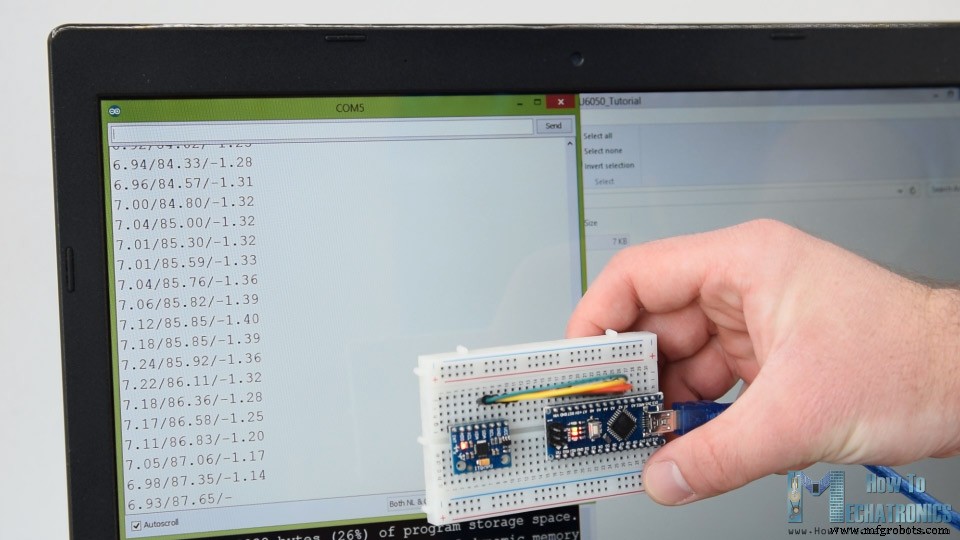
MPU6050方向追跡–3D視覚化
/*
    Arduino and MPU6050 IMU - 3D Visualization Example
     by Dejan, https://howtomechatronics.com
*/
import processing.serial.*;
import java.awt.event.KeyEvent;
import java.io.IOException;
Serial myPort;
String data="";
float roll, pitch,yaw;
void setup() {
  size (2560, 1440, P3D);
  myPort = new Serial(this, "COM7", 19200); // starts the serial communication
  myPort.bufferUntil('\n');
}
void draw() {
  translate(width/2, height/2, 0);
  background(233);
  textSize(22);
  text("Roll: " + int(roll) + "     Pitch: " + int(pitch), -100, 265);
  // Rotate the object
  rotateX(radians(-pitch));
  rotateZ(radians(roll));
  rotateY(radians(yaw));

  // 3D 0bject
  textSize(30);
  fill(0, 76, 153);
  box (386, 40, 200); // Draw box
  textSize(25);
  fill(255, 255, 255);
  text("www.HowToMechatronics.com", -183, 10, 101);
  //delay(10);
  //println("ypr:\t" + angleX + "\t" + angleY); // Print the values to check whether we are getting proper values
}
// Read data from the Serial Port
void serialEvent (Serial myPort) {
  // reads the data from the Serial Port up to the character '.' and puts it into the String variable "data".
  data = myPort.readStringUntil('\n');
  // if you got any bytes other than the linefeed:
  if (data != null) {
    data = trim(data);
    // split the string at "/"
    String items[] = split(data, '/');
    if (items.length > 1) {
      //--- Roll,Pitch in degrees
      roll = float(items[0]);
      pitch = float(items[1]);
      yaw = float(items[2]);
    }
  }
}Code language: Arduino (arduino)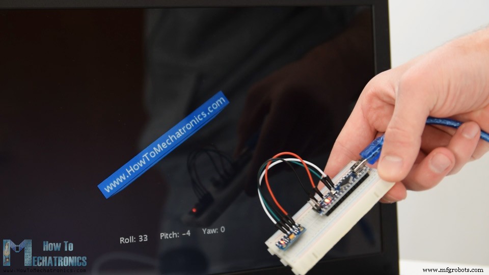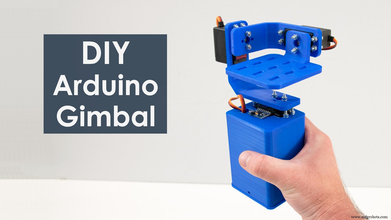
製造プロセス