


煙道ガス洗浄技術とシステム
煙道ガス洗浄技術とシステム
環境汚染は、現在、世界中で最大の問題の1つです。一連の地球環境問題から、環境と資源が人間の生存と発展のための基本的な必需品であることに、ますます多くの人々が気づいています。ほとんどの技術プロセスの産物である煙道ガスは、さまざまな固体粒子で汚染されています。ガスをさらに使用するため(十分な発熱量がある場合)、またはガスを大気中に放出するために、ガスを洗浄する必要があります。ただし、大気への排出量の管理には費用がかかり、運営組織への経済的見返りはほとんどありません。
過去数年間で、さまざまな国の排出規制の分野における態度、教育、責任、および規制が完全に変化しました。大気汚染の悪影響から未来の世代を救うために、排出規制は時間の経過とともに厳しくなっています。現在、いくつかの組織は大気汚染に対する態度を急速に変えており、汚染防止活動に積極的に関与しています。現在、組織は、「クリーンな」製品を製造する責任ある組織であると一般に見られることを望んでいます。市場は現在、ますます多くの「クリーンな」製品を要求しているため、これは部分的に市場主導型です。現在の状況にある顧客は、環境に対する責任と、クリーンな環境を持つことのメリットの両方について、より教育を受けています。
煙道ガス洗浄システムの目的は、環境と健康に有害な物質の大気への排出を減らすことです。これには、たとえば重金属、ダイオキシン、酸性化や富栄養化を引き起こす物質。煙道ガスに含まれる物質の中には有毒で発がん性があるものがあるため、それらの排出量を減らすことが重要です。森林や湖の酸性化は、煙道ガスから硫黄と窒素の酸化物を除去することによって大幅に削減されました。
冶金、化学、火力発電所の技術プロセスでは、通常は粉塵を含んだ高温の廃煙道ガスが発生します。これらのガスの組成と量は、技術プロセスと原材料の性質によって異なります。廃煙道ガスの排出は、実際には使用される原材料、およびこれらのプラントで行われるプロセスと反応の結果です。煙道ガスには、二酸化炭素、一酸化炭素、硫黄酸化物(SO2およびSO3)および窒素(NOx)、水素、硫化水素(H2S)、フッ素(HFの形)、塩素(HClの形)が含まれます。 )、ヒ素、水銀、揮発性有機化合物(VOC)、水蒸気、ほこりなど。水蒸気は無害ですが、スタック出口で目に見えるプルームの原因となります。
高温で行われるいくつかの技術的プロセスがあります。さらに、これらのプロセスの多くは原材料を処理し、それらのいくつかは罰金の形をとっています。したがって、これらすべてのプロセスは、汚染ガスや粒子状物質を大気中に放出する傾向があります。これは次に、プラント周辺の空気の質に影響を与えます。空気の質を改善し保護するために、排出量を削減するためにさまざまな汚染防止装置が使用されています。何年も前から、汚染防止装置は、汚染物質の量が非常に多いか、本質的に有毒であるプロセスにのみ使用されていました。これらの機器は、ある程度の回復価値がある場所でも以前に使用されていました。しかし、現在のシナリオでは、環境規制がますます厳しくなり、環境に対する社会の関心が高まるにつれて、すべての技術プロセスの排出量を調査し、削減するためにすべての領域に機器を設置する必要があります。排出量を可能な限り最小限に抑えます。
通常は技術プロセスに起因する大気汚染源の少なくとも5つの主要なグループがあり、それぞれが削減のための特定のベストプラクティス技術を備えています。これらのグループ化は、強酸ガス濃度に遭遇するため、包括的なリストを構成しません。硫酸プラントなどの代替の煙道ガス洗浄技術が実装されます。ガス洗浄技術のこれら5つの主要なグループは、(i)ダストおよび粒子放出制御、(ii)SO2 / HClおよびHF制御などの酸性ガス、(iii)NOx削減制御、(iv)酸性ミストおよびその他のエアロゾルに関連しています。制御、および(v)水銀、ダイオキシン/フランおよびVOCの制御。酸性ガス固定技術の場合、製品の廃棄は常に課題です。ほとんどのアプリケーションでは、廃棄物はそれに伴う必要な運用コストで単純に埋め立てられます。これら5つのグループのガス洗浄技術の排出制御装置は、基本的に2つのタイプ(i)粉塵および粒子状排出制御装置と(ii)ガス状排出制御装置です。この記事では、粉塵と粒子状物質の排出制御システムに焦点を当てています。
一般的な高温ガス洗浄の問題は、おそらく業界で最も厄介な問題です。この問題は通常、700℃から1,500℃の範囲の温度でガスに分散した非常に細かい粒子に関連しているため、困難です。場合によっては、さらに高い温度が関係する可能性があります。微細なエアロゾルと高温が関係するため、通常のアプローチでは通常問題を解決できません。したがって、この分野の進歩はそれほど急速ではありませんでした。高温ガス洗浄に関連する基本的な問題は、経済的問題と洗浄の基本的な要件です。
場合によっては、廃ガスは実質的な価値のある材料であるため、または粒子状物質が除去された場合に可燃性であり、熱またはエネルギーの形で回収されるガスが残り、処理する。他の例では、粒子状、ガス状、または通常の組み合わせのいずれかの排水の経済的価値は非常に小さいので、処分のコストはかなりの問題を表します。このような場合、大気汚染を防ぐために必要な清掃または除去は、無形の利益しか得られないものです。
第二のカテゴリーでは、業界の要望は、生産コストの増加という形で負担をかけることなく、最小限のコストで洗浄を行うことです。地域の大気汚染や財産や一般市民への危害の可能性を防ぐための費用は、通常、良好な広報活動以外に具体的な回復がない場合です。
これらのガスの効果的な洗浄は、不純物の多様性のために深刻な技術的問題を引き起こします。高効率のガス洗浄システムは、高温の冶金および火力発電所の信頼性の高い運転と長いキャンペーン寿命に不可欠であり、オペレーターが関連する汚染防止基準を満たすことを可能にします。ガス冷却および洗浄プラントの選択は、技術的な実現可能性、経済的受容性、および環境適合性に関して重要です。さらに、ガス洗浄システムは、可能な限り最高の環境保護を提供しながら、最高レベルの洗浄効率、安全性、および信頼性を実現するように設計する必要があります。
ガス洗浄システムの設計の重要な基準は、(i)1時間あたりのN cum単位のガス量、(ii)ガスの化学組成、(iii)ガスの水分含有量、(iv)ガスの温度、(v )1時間あたりのkg単位のガスのダスト含有量、(vi)腐食性、研磨性などのダストの特性、(vii)ダストの粒子サイズ範囲、(viii)排出基準、(ix)ガスの爆発特性、(x)衛生的な設計、(xi)オンラインまたはオフラインのシステム、および(xii)建設資材。
ガス洗浄システムの設計には、3つの主要な考慮事項があります。 1つ目は、放出されたほこりやガスを捕らえ、煙が充満した作業領域を防ぐように設計されたフードです。 2つ目は、フードに捕らえられたガスやほこりは、大気に放出する前に洗浄する必要があるということです。 3つ目は、収集されたほこりは、空気や小川に再飛散して再び汚染問題にならないように処分することです。
冶金炉から出る煙道ガスは、しばしば高温(700℃から1,500℃以上)と高いダスト含有量を持っています。したがって、ガス洗浄システムでこれらのガスを処理する前に、これらのガスを400℃未満の温度に冷却する必要があります。実際には、いくつかのガス冷却方法が使用されます。これらは、(i)廃熱ボイラー、(ii)空気による間接冷却、(iii)水による間接冷却、および(iv)水による蒸発冷却です。
廃熱ボイラーは主に、連続的なガス流量で煙道ガスを生成する技術プロセスからの煙道ガスを冷却するために使用されます。これにより、廃熱ボイラーを使用したガス冷却の適用が可能になり、良好な運転結果が得られます。
空気による間接冷却によるガス冷却システムは、(i)冷却空気の温度がプロセスガスの露点よりも低く、酸の凝縮が発生するなどのいくつかの欠点があるため、実際にはほとんど使用されません。装置の腐食を引き起こすより冷たい壁、(ii)粘着性のほこりによる付着および閉塞のリスク、(iii)高温(550℃より高い)でのガスの保持時間が長く、追加のSO3の形成を引き起こすガスの露点が上昇し、(iv)ガス流量が変動する場合、ガス出口温度の制御が困難になります。
水による間接冷却によりガスを冷却するシステムが頻繁に使用されています。この場合、煙道ダクトの周囲には冷却水が流れる水管があります。チューブのサイズと水のパラメータ(圧力と流量)は、加熱された水の温度が常にその蒸発レベルを下回ったままになるようにする必要があります。システムは蒸気と蒸気処理に関連する規制の問題を回避しますが、システムの欠点は、よりかさばる機器と大量の冷却水の処理に関連しています。
水による蒸発冷却は、ガス流量が変動するガスを冷却するための間接空冷または廃熱ボイラーの適切な技術的代替手段です。最新の蒸発冷却装置は、特殊な種類のスプレーノズル、いわゆる2成分ノズル(水と加圧空気)を使用しています。これにより、クーラー出口でのガス温度の柔軟な操作と高感度の制御が可能になります。この機能は、酸性ミストの凝縮を引き起こし、その結果、後続の高温ガス沈殿装置でのダストの湿潤と湿ったダスト堆積物の生成、および腐食を引き起こす可能性のある過度のガス温度低下を回避するために非常に重要です。蒸発冷却器を使用する利点は次のとおりです。(i)粒子状金属化合物の存在下での高温(550℃以上)での蒸発冷却器の上流でのガスの保持時間が短いため、蒸発冷却によりガス中の追加のSO3の形成が減少します。触媒として機能しています。 (ii)蒸発冷却器の下流では、SO3の形成が抑制され、(iii)電気集じん器(ESP)の性能を向上させるためにガスを水で調整し、(iv)ガイドベーンのような内部構造は必要ありません。
現在利用可能なガス洗浄装置には約40種類あり、共通の特性に基づいて、(i)ミストエリミネーター、(ii)集塵機(集塵機とも呼ばれる)の5つの主要なタイプに分類できます。およびサイクロン、(iii)湿式集塵機、(iv)フィルター、および(v)ESP。さらに、ガス洗浄システムは、乾式粉塵分離の技術または湿式粉塵分離の技術に基づくことができる。乾式粉塵分離技術では、技術プロセスの要件に基づいて、水によるガスの調整が必要になる場合があります。ガスのコンディショニングは、コンディショニングタワーに窒素と一緒に水を注入して、直径約150マイクロメートルの液滴を含むウォーターミストを生成することによって実行されます。タワー内のガスの滞留時間は、すべての液滴がコンディショニングタワーの出口で完全に蒸発するように制御されます。
粒子除去装置は、基本的に、粒子を含むガス流が、粒子が外力によって作用されるか、または障害物を遮断させられる領域を通過し、それによってそれらをガス流から分離するという原理に基づいて動作する。外力が作用すると、粒子はガス流の方向とは異なる方向の速度成分を獲得します。外力による粒子分離に基づく分離装置を設計するためには、そのような条件下での粒子の運動を計算することが不可欠です。
適切な粒子状物質排出制御システムの予備的な選択は、通常、4つの項目、すなわち(i)洗浄するストリーム内の粒子状物質濃度、(ii)除去する粒子のサイズ分布、(iii)ガスフローの知識に基づいています。 (iv)最終的な許容粒子状物質排出率。所定の流量で必要な効率を提供できるシステムが選択されると、通常、建設と運用の総コストに基づいて最終的な選択が行われます。コレクターのサイズ、したがってそのコストは、洗浄されるガスの体積流量に正比例します。デバイスのコストに影響を与える操作上の要因は、ユニット全体の圧力降下、必要な電力、および必要な水の量です(ウェットスクラビングシステムの場合)。ガス流から粒子を除去するデバイスは、次の物理的メカニズムの1つ以上に依存しています。
沈降 –粒子を含むガス流は、デバイスまたはチャンバーに導入され、重力下でチャンバーの床に沈殿します。このタイプのデバイスは、セトリングチャンバーと呼ばれます。
電場での荷電粒子の移動 –粒子を含むガス流は、粒子が帯電してから電界にさらされるデバイスに導入されます。結果として生じる粒子への静電力により、粒子はデバイスの表面の1つに移動し、そこで保持および収集されます。このタイプのデバイスはESPと呼ばれます。
慣性堆積 –ガス流がその経路内のオブジェクトの周りを流れるときに方向を変えると、浮遊粒子は慣性のために元の方向に移動し続ける傾向があります。この原理に基づく粒子収集装置には、サイクロン、スクラバー、フィルターが含まれます。
ブラウン拡散 –ガスに浮遊している粒子は、常にブラウン運動をしています。ブラウン運動は、媒体に浮遊する粒子のランダムな運動です。この動きのパターンは、通常、流体サブドメイン内の粒子の位置のランダムな変動と、それに続く別のサブドメインへの再配置で構成されます。ガス流が障害物の周りを流れるとき、粒子の自然なランダムな動きにより、粒子が障害物と接触し、そこで付着して収集されます。ブラウン運動は粒子が小さいほど顕著であるため、分離メカニズムとして拡散に基づくデバイスが小さい粒子に最も効果的であると予想されます。
特定の場合に使用するデバイスの選択に影響を与える重要なパラメータは、粒子径「Dp」です。上記の物理的メカニズムは、粒子のサイズによって効果が大きく異なります。したがって、粒子除去装置の有効性は粒子サイズの関数です。
直径「Dp」の粒子のガス洗浄装置の収集効率「N(Dp)」は、次の式で定義されます。ガスのcumあたりの直径Dpの粒子)。粒子数に基づくデバイスの全体的な効率「N」は、式N =1 –(ガスアウトのカムあたりの粒子数)/(ガスインのカムあたりの粒子数)で与えられます。これらの効率は、デバイスの入口側と出口側での粒子サイズ分布関数で表すことができます。
粒子状物質制御装置にはいくつかの異なるクラスがあります。最も単純な粒子制御装置は沈降チャンバーであり、ガス速度が遅くなる大きなチャンバーであり、重力によって粒子を沈降させることができます。サイクロンは、ガス流全体をテーパー管内でらせん状に流すことで作動します。遠心力により、粒子は外側に移動し、チューブの壁に集まります。粒子は壁を滑り落ちて底に落ち、そこで除去されます。クリーンガスは通常、その流れを逆転させ、サイクロンの上部から排出されます。
ESPは、電界内の荷電粒子にかかる静電力を利用して、粒子をガス流から分離します。 2つの電極間に高電圧降下が確立され、結果として生じる電界を通過する粒子が電荷を獲得します。荷電粒子は、反対に帯電したプレートに移動して収集され、クリーンなガスがデバイスを通過します。定期的に、堆積したほこりの層を振り落とすために、プレートをラップで清掃します。
さまざまなフィルターは、粒子を含んだガスが繊維やフィルターマットなどの収集要素の集合体を通過するという原理に基づいて動作します。ガスが集合体を通過すると、粒子がコレクターに蓄積します。
スクラバーと呼ばれる湿式収集装置は、粒子と水滴との衝突に基づいて動作します。水滴はサイズが大きいため、ガスから簡単に分離できます。
沈降チャンバーやサイクロンなどの機械的コレクターは、通常、他のコレクターよりもはるかに安価ですが、通常、粒子の除去には中程度の効率しかありません。それらは小さな粒子よりも大きな粒子にはるかに優れているため、特に高い粒子負荷で、より効率的な最終制御装置のプレクリーナーとして頻繁に使用されています。 ESPは、非常に高い除去効率で、比較的低い圧力損失で大量のガスを処理できます。ただし、ESPは高価であり、プロセスの動作条件の変化に対して比較的柔軟性がありません。ファブリックフィルター(バッグフィルター)は非常に効率が高い傾向がありますが、高価であり、通常は乾燥した低温条件に制限されます。スクラビングはまた、高い効率を達成することができ、ガス状汚染物質を粒子と同時に除去できるという補助的な利点を提供します。ただし、スクラバーは、圧力損失が高く、処理または廃棄が必要な湿ったスラッジを生成するため、操作に費用がかかる可能性があります。
セトリングチャンバー
重力沈降は、流れるガス流から粒子を分離する最も明白な手段である可能性があります。沈降チャンバーは、粒子を含んだガスが流れ、床にダスト粒子が沈降する単純な水平チャンバーです。これは、原則として、流出ガスの流れが流れ、流れの中の粒子が重力によって床に沈殿する、単なる大きな箱です。沈降チャンバーを通過するガス速度は、沈降粒子が再飛散しないように十分に低く保つ必要があります。ガス速度は通常、ダクトを十分に大きいチャンバーに拡張することによって低下し、その結果、十分に低い速度が得られます。原則として、沈降チャンバーを使用して最小の粒子を除去することもできますが、そのようなチャンバーの長さの実際的な制限により、約50マイクロメートルを超える粒子の除去への適用が制限されます。したがって、沈殿チャンバーは通常、ガス流を他の収集装置に通す前に、大きくて研磨性のある粒子を除去するためのプレクリーナーとして使用されます。
沈降チャンバーは、(i)シンプルな構造と低コスト、(ii)小さな圧力降下、および(iii)水を必要としない粒子の収集という利点を提供します。沈殿チャンバーの主な欠点は、必要なスペースが大きいことです。実際、チャンバーは、粒子が収集されるために沈降する距離がデバイス全体の高さよりもかなり小さいように、いくつかの比較的近接した水平プレートを含むことができる。図1は、単純な重力沈降チャンバーの設計を示しています。
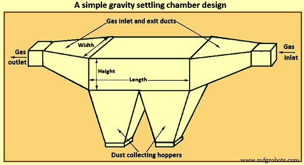
図1単純な重力沈降チャンバーの設計
沈降チャンバーの性能を分析する際の重要な特徴は、デバイスを通るガスの流れの性質です。これに関して、3つの基本的な理想的な流れの状況、すなわち(i)層流、(ii)粒子の垂直混合のないプラグフロー(断面全体で均一な速度)、および(iii)完全な垂直混合のあるプラグフローを区別できます。粒子。
層流は、放物線型の速度プロファイルによって特徴付けられます。このような流れは、乱流への遷移のレイノルズ数よりも低いレイノルズ数でのみ実現されます。層流では、チャンバーの床から「h」の高さの粒子が沈降するのに必要な時間は「h / V」です。ここで、Vは粒子の沈降速度です。層流では、粒子の垂直方向の混合はありません。ブラウン運動の影響は、通常、沈降による安定した下向きの動きに比べて無視されます。
層流沈降チャンバーでは、ガス速度プロファイルは放物線状であり、中央の流線より下の粒子が沈降すると、流体の移動が遅くなるため、チャンバー内での滞留時間は、より高い流線上での滞留時間よりも長くなります。一方、最初に中央の流線より上にある粒子は、中央の流線を通過するまで落下するときに、より速く移動する流線に遭遇します。
2番目のフローカテゴリは、粒子の垂直方向の混合がないプラグフローです。このタイプの流れは、ある意味で、粒子の垂直混合が依然として無視されるという点で層流の近似ですが、平坦な速度プロファイルが想定され、粒子はすべてそれらの沈降速度で沈降します。 2番目のタイプのフロー状況は、粒子の垂直方向の混合がないプラグフローの状況です。この状況では、粒子はチャンバーの入り口全体に均一に分布していると想定されます。粒子が収集されるかどうかは、収集面の上の入口の高さ「h」によってのみ決定されます。臨界高さ「h*」は、「h」が「h *」以下で入るすべての粒子が収集され、「h」が「h*」より大きい粒子が収集を逃れるように定義できます。
>3番目のカテゴリである完全な垂直混合を伴うプラグフローは、乱流です。乱流沈降チャンバーでは、乱流混合により、ガス速度はチャンバー全体で均一であると想定されます。さらに、チャンバーのコア内の乱流混合は、粒子が沈降する傾向を圧倒し、チャンバー全体で垂直方向に均一な粒子濃度を維持します。沈降による除去は、チャンバー底部の薄層で発生すると考えられます。
レイノルズ数が4,000を超える場合、長方形のチャネル内の流れは乱流であると見なすことができます。層流沈降チャンバーでは、粒子はチャンバーの床から上のすべての高さに沈降します。分析の鍵は、粒子が流線を横切って落下するときの粒子の全体的な滞留時間を計算することです。乱流沈降チャンバーでの収集のメカニズムは、最終的には重力下での粒子の沈降に基づいていますが、層流チャンバーでの収集のメカニズムとはかなり異なります。違いは、チャンバー内の乱流によるものです。チャンバー内のバルクフローでは、乱流混合が十分に激しいため、粒子はフローに圧倒されて沈降しません。乱流混合は、チャンバーの高さ全体にわたって均一な粒子濃度を維持すると想定されています。チャンバーの床の非常に近くに、粒子が床までの短い距離に定着する薄い層が存在すると想定することができます。したがって、流れのコアで激しく混合された粒子がこの層に入ると、床に落ち着きます。
サイクロンセパレーター
サイクロン分離器は、回転するガス流によって生成される遠心力を利用して粒子をガスから分離するガス洗浄装置です。標準的な接線方向の入口垂直逆流サイクロン分離器を図2に示します。ガスの流れはサイクロンの湾曲した形状に従うように強制されますが、流れの中の粒子の慣性により、粒子は外壁に向かって移動し、そこで衝突して集めました。半径「r」の円形経路を接線速度「vA」で移動する質量「m」の粒子には、「m(vA)2/r」の遠心力が作用します。 「vA」=10m / s、「r」=0.5 mの一般的な値では、この力は同じ粒子の重力の20.4倍です。したがって、サイクロンの形状では、沈降のみの力よりも粒子にかかる力が大幅に向上することがわかります。
サイクロンでは、回転するガス流中の粒子は、デバイスを流れるときに外壁に徐々に近づきます。図2に示すように、ガスストリームは、デバイスの一方の端からもう一方の端に流れるときに、完全に数回転することができます。サイクロン分離器、所与のガス流量、および内外半径の設計では、サイクロン本体の長さは、所与のサイズの粒子に対して所望の収集効率が達成されることを保証することである。サイクロンの本体の長さは、ガス流量によってガス流によって実行される回転数に関連しているため、設計では、指定された収集効率を達成するために必要な回転数を計算することがよくあります。
回転運動がガス流に与えられる方法が異なるサイクロン分離器に利用可能な様々な設計があります。従来のサイクロンは、(i)逆流サイクロン(接線入口および軸流入口)、(ii)直流サイクロン、および(iii)インペラコレクターの3つのカテゴリに分類できます。
図2は、接線方向の入口を備えた従来の逆流サイクロンを示しています。汚れたガスはサイクロンの上部から入り、接線方向に入るために回転運動をします。粒子は遠心力によって壁に押し付けられ、重力によって壁から落下します。サイクロンの底部では、ガスの流れが逆になり、サイクロンの上部に残る内核を形成します。逆流アキシャルインレットサイクロンでは、インレットガスがサイクロンの軸に沿って導入され、上部の永久ベーンによって遠心運動が与えられます。
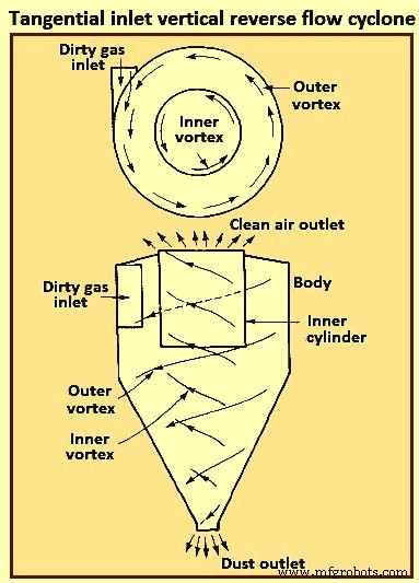
図2タンジェンシャルインレット垂直逆流サイクロン
ストレートスルーフローサイクロンでは、空気の内側の渦が(方向を逆にするのではなく)下部に残り、最初の遠心運動は上部のベーンによって与えられます。このタイプは、大きな粒子を除去するためのプレクリーナーとして頻繁に使用されます。このサイクロンの主な利点は、圧力損失が低く、体積流量が多いことです。
インペラコレクターでは、ガスは多羽根インペラに垂直に流入し、粒子がサイクロンの周囲の環状スロットに投げ込まれる間、その周囲のインペラによって押し出されます。このサイクロンの主な利点は、そのコンパクトさです。サイクロンの主な欠点は、サイクロン内の固形物の蓄積から詰まる傾向があることです。
サイクロンは、金属またはセラミックの任意の材料で構成できます。それらは、高温、研磨粒子、または腐食性雰囲気に耐えることができます。集められた粒子が壁を滑り落ちてホッパーに到達できるように、内面が滑らかである必要があります。サイクロンには可動部品がないため、操作は通常簡単で、比較的メンテナンスが不要です。資本コストが低く、メンテナンスフリーの操作であるため、ESPなどのより効率的な最終制御装置のプレクリーナーとして使用するのに理想的です。サイクロンは伝統的に比較的低効率のコレクターと見なされてきましたが、現在利用可能な一部のサイクロンは、5マイクロメートルを超える粒子に対して98%を超える効率を達成できます。通常、サイクロンは15マイクロメートルから20マイクロメートルを超える粒子に対して90%の効率を日常的に達成します。
図3は、r3で回転するガス流の水平面に接線方向に入る粒子を示しています。 「m(vA)2 / r」の遠心力のため、粒子は流れの流線を横切って外側の経路をたどります。その速度ベクトルには、接線成分(vA)と半径成分(Vr)があります。軸方向成分(vZ)もあります。
いわゆる層流サイクロン分離器は、層流沈降チャンバーという意味での層流ではなく、図3に示すように流線がサイクロンの輪郭に沿った摩擦のない流れを持っています。
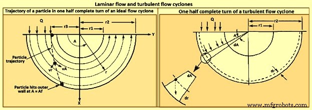
図3層流と乱流サイクロン
乱流サイクロン分離器のモデルを図3に示します。乱流混合のため、粒子濃度はサイクロン全体で均一であると想定され、乱流沈降チャンバーの場合と同様に、外壁。
サイクロン収集効率は、(i)粒子サイズ、(ii)粒子密度、(iii)入口ガス速度、(iv)サイクロン本体の長さ、(v)ガス回転数、および(vi)サイクロン壁の滑らかさの増加とともに増加します。一方、サイクロン効率は、(i)サイクロン径、(ii)ガス出口ダクト径、(iii)ガス入口面積の増加に伴い低下します。寸法比が固定されている特定のサイクロンの場合、サイクロンの直径が小さくなると、収集効率が向上します。サイクロン分離器の設計は、収集効率、圧力損失、およびサイズの間の妥協点を表しています。 Higher efficiencies need higher pressure drops (i.e., inlet gas velocities) and larger sizes (i.e. body length). The dimensions required to specify a tangential-entry, reverse-flow cyclone are shown in Fig 4.
Besides collection efficiency the other major consideration in cyclone specification is pressure drop. While higher efficiencies are achieved by forcing the gas through the cyclone at higher velocities, to do so results in an increased pressure drop. Since increased pressure drop needs increased energy input into the gas, there is ultimately an economic trade-off between collection efficiency and operating cost. Cyclone pressure drops normally range from 250 Pa to 4,000 Pa.
Electrostatic precipitator
ESP is one of the most widely used particulate control device. It has wide size ranges. The ESP chamber consists of two electrodes, the discharge and the collecting electrodes. Between the electrodes, the gas contains free electrons, ions, and charged particles. The species contributing to the space charge density are ions, electrons, and charged particles. The gas molecules capture all the free electrons so that only the ions and charged particles contribute space charge density. Actually, ionic current flows in the direction of the electric field consisting of ions charged with the same polarity as the charging electrode and moving to the collecting electrode. The ions migrate to the collecting electrode with a velocity large enough to be unaffected by the turbulent flow in the chamber.
The basic principle of operation of the ESP is that the particles are charged, and then an electric field is imposed on the region through which the particle-laden gas is flowing, exerting an attractive force on the particles and causing them to migrate to the oppositely charged electrode at right angles to the direction of gas flow. ESP differs from mechanical methods of particle separation in that the external force is applied directly to the individual particles rather than indirectly through forces applied to the entire gas stream (e.g. in a cyclone separator). Particles collect on the electrode. If the particles collected are liquid, then the liquid flows down the electrode by gravity and it is removed at the bottom of the device. If the particles are solid, the collected layer on the electrode is removed periodically by rapping the electrode.
Particle charging is achieved by generating ions by means of a corona established surrounding a highly charged electrode like a wire. The electric field is applied between that electrode and the collecting electrode. If the same pair of electrodes serves for particle charging and collecting, the device is called a single-stage ESP (Fig 4). A wire serving as the discharge electrode is suspended down the axis of a tube and held in place by a weight attached at the bottom. The sides of the cylinder form the collecting electrode. The collected particles which form a layer on the collecting electrode are removed to the dust hopper by rapping the collecting electrode. In a two-stage ESP, separate electrode pairs perform the charging and collecting functions.
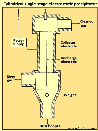
Fig 4 Cylindrical single-stage electrostatic precipitator
Most industrially generated particles are charged during their formation by such means as flame ionization and friction, but normally only to a low or moderate degree. These natural charges are far too low for electrostatic precipitation. The high-voltage DC (direct current) corona is the most effective means for particle charging and is universally used for electrostatic precipitation. The corona is formed between an active high voltage electrode such as a fine wire and a passive ground electrode such as a plate or pipe. The corona surrounding the discharge electrode can lead to the formation of either positive or negative ions which migrate to the collecting electrode. The ions, in migrating from the discharging to the collecting electrode, collide with the particulate matter and charge the particles.
Since the gas molecule ions are many orders of magnitude smaller than even the smallest particles and because of their great number, virtually all particles that flow through the device become charged. The charged particles are then transported to the collecting electrode, to which they are held by the electrostatic attraction. The particles build a thickening layer on the collecting electrode. The charge slowly bleeds from the particles to the electrode. As the layer grows, the charges on the most recently collected particles are to be conducted through the layer of previously collected particles. The resistance of the dust layer is called the dust resistivity.
As the particle layer grows in thickness, the particles closest to the plates lose most of their charge to the electrode. As a result, the electrical attraction between the electrode and these particles is weakened. However, the newly arrived particles on the outside layer have a full charge. Because of the insulating layer of particles, these new particles do not lose their charge immediately and thus serve to hold the entire layer against the electrode. Finally, the layer is removed by rapping, so that the layer breaks up and falls into a collecting hopper. ESPs are normally employed for gas cleaning when the volumetric throughput of gas is high.
The mechanism for particle charging in a ESP is the generation of a supply of ions which attach themselves to the particles. The corona is the mechanism for forming ions. The corona can be either positive or negative. A gas normally has a few free electrons and an equal number of positive ions, a situation which is exploited in generating a corona. When a gas is placed between two electrodes, small amount of current results as the free electrons migrate to the positive electrode and the positive ions migrate to the negative electrode.
In the positive corona discharge electrode, the wire in the cylindrical ESP (Fig 4) is at a positive potential. The few free electrons normally present in the gas migrate toward the wire. As the electrons approach the wire, the electrons’ energy is increased because of an increase in the attractive force. These free electrons collide with gas molecules, the collision leading in some cases to the ejection of an electron from the molecule, producing two free electrons and a positive ion. The two free electrons continue toward the positive electrode, gaining energy, until they collide with two more gas molecules, producing four free electrons and two positive ions. This process is referred to as an electron avalanche.
The positive ions formed migrate to the negative electrode. It is these positive ions which migrate across the entire device to the negative electrode that collide with and attach to the particles in the gas. The region immediately surrounding the wire in which the electron avalanche is established is the corona. Thus, with a positive corona the particles become positively charged. The term ‘corona’ arises from the fact that the electron avalanche is frequently accompanied by the production of light. In the negative corona the discharge electrode is maintained at a negative potential.
The electron avalanche begins at the outer surface of the wire and proceeds radially outward. Close to the wire the electrons are sufficiently energetic to form positive ions upon collision with gas molecules, thus initiating the electron avalanche. The positive ions formed migrate the short distance to the wire. As the electrons migrate outward into a region of lower electric field strength, they are slowed down by collisions with gas molecules. These electrons eventually have lower energy than those which are accelerated toward the positive electrode in the positive corona. These relatively low energy electrons, rather than ejecting an electron from the gas molecule upon collision, are absorbed by the gas molecules to produce negative ions. The formation of negative ions, which begins to occur at the outer edge of the corona, essentially absorbs all the free electrons produced in the electron avalanche at the wire surface. These negative ions then migrate to the positive electrode, in the course of which attaching to gas molecules and forming negative ions.
For a negative corona to be effective, it is necessary that the gas molecules can absorb free electrons to form negative ions. Sulphur dioxide is one of the best electron absorbing gases of those present in flue gases. Oxygen, CO2, and H2O are also effective electron absorbers. The negative corona is normally more stable than the positive corona, so it is preferred in most industrial applications. A by-product of the negative corona is the production of ozone (O3). The positive corona does not need an electron-absorbing gas.
As the ESP is operated, a layer of the collected material builds up on the collecting electrode. Particle deposits on the precipitator collection surface are to possess at least a small degree of electrical conductivity in order to conduct the ion currents from the corona to ground. The minimum conductivity required is around 10 to the power -10 per ohm-centimeter (resistivity of 10 to the power 10 ohm-centimeter). This conductivity is small compared to that of ordinary metals but is much greater than that of good insulators such as silica and most plastics. The resistivity of a material is determined by establishing a current flow through a slab of known thickness of the material.
As long as the resistivity of the collected dust layer is less than about 10 to the power 10 ohm-centimeter, the layer surrender its charge to the electrode. At the room temperature, a typical dust has a resistivity of around 10 to the power 8 ohm-centimeter. This is because of a layer of water on the surface of the particles. As the temperature is increased beyond 100 deg C, the water is evaporated and the resistivity increases to a value characteristic of the collected solids. When the resistivity of the layer exceeds around 10 to the power 10 ohm-centimeter, the potential across the layer increases so that the voltage which can be maintained across the ESP decreases and the collection efficiency decreases. The electrical resistivity of collected particulate matter depends on its chemical composition, the constituents of the gas, and the temperature.
Particle charging in ESP occurs in the gas space between the electrodes where the gas ions generated by the corona bombard and become attached to the particles. The gas ions can reach concentrations as high as 10 to the power 15 ions per cubic meter. The level of charge attained by a particle depends on the gas ion concentration, the electric field strength, the conductive properties of the particle, and the particle size. A 1 micrometer particle typically acquires the order of 300 electron charges, whereas a 10 micrometer particle can attain 30,000 electron charges. Predicting the level of charge acquired by a particle is necessary in order to predict the particle’s migration velocity, on the basis of which the collection efficiency can be calculated for a given set of operating conditions.
There are actually two mechanisms by which particles become charged in an ESP. In the first mechanism particle charging occurs when ions which are migrating toward the collecting electrode encounter particles to which they become attached. In migrating between the electrodes the ions follow the electric flux lines, which are curves everywhere tangent to the electric field vector. When the particle first enters the device and is uncharged, the electric flux lines deflect toward the particle, resulting in the capture of even a larger number of ions than are captured if the ions have followed their normal path between the electrodes. As the particle becomes charged, ions begin to be repelled by the particle, reducing the rate of charging. Eventually, the particle acquires a saturation charge and charging ceases. This mechanism is called ion bombardment or field charging.
The second mode of particle charging is diffusion charging, in which the particle acquires a charge by virtue of the random thermal motion of ions and their collision with and adherence to the particles. Diffusion charging occurs as the ions in their random thermal motion collide with a particle and surrender their charge to it. In that sense the mechanism of diffusion charging is identical to that of the diffusion of uncharged vapour molecules to the surface of a particle. However, because both the particle and the ions are charged, the random thermal motion of the ions in the vicinity of a particle is influenced by an electrostatic force. This force gives rise to a tendency of the ions to migrate away from the particle as the particle charge increases. The overall flux of ions to a particle hence is both the random diffusive motion and the electrical migration.
The theories of both field and diffusion charging, in their full generality, are quite complex and have received a great deal of attention. Strictly speaking, field and diffusion charging occur simultaneously once a particle enters an ESP, and hence to predict the overall charge acquired by a particle, one is to consider the two mechanisms together. However, since the diffusion charging is predominant for particles smaller than around 1 micrometer in diameter and field charging is predominant for particles larger than around 1 micrometer, the two mechanisms frequently are treated in ESP design as if they occur independently. In doing so, one estimates the total charge on a particle as the sum of the charges resulting from each of the two separate mechanisms.
Filtration of particles from gas streams
A major class of particulate air pollution control devices relies on the filtration of particles from gas streams. A variety of filter media is employed, including fibrous beds, packed beds, and fabrics. Fibrous beds used to collect airborne particles are typically quite sparsely packed, usually only around 10 % of the bed volume being fibers. Packed bed filters consist of solid packing normally in a tube and tend to have higher packing densities than do fibrous filters. Both fibrous and packed beds are widely used in the ventilation systems. Fabric filters are frequently used to remove solid particles from industrial gases, whereby the dusty gas flows through fabric bags and the particles accumulate on the cloth.
The physical mechanisms by which the filtration is accomplished vary depending on the mode of filtration. Conventional sparsely packed fibrous beds can be viewed as assemblages of cylinders. In such a filter, the characteristic spacing between fibers is much larger than the size of the particles being collected. Thus the mechanism of collection is not simply sieving, in which the particles are trapped in the void spaces between fibers. Rather, the removal of particles occurs by the transport of particles from the gas to the surface of a single collecting element. Because the filtration mechanisms in a fibrous bed can be analyzed in terms of a single collector, it is possible to describe them in considerable theoretical detail.
Packed-bed filters are sometimes viewed as assemblages of interacting, but essentially separate, spherical collectors, although the close proximity of individual packing elements casts doubt as to the validity of this approach. Because of the relatively closer packing in packed-bed filters, and the resulting difficulty of describing the particle collection process in clean theoretical terms, predicting collection in such systems is more empirically based than for fibrous filters. Fabric filter efficiencies must be predicted strictly empirically since the accumulated particle layer actually does the collecting.
A fibrous filter bed is viewed as a loosely packed assemblage of single cylinders. Even though the fibers are oriented in all directions in the bed, from a theoretical point of view the bed is treated as if every fiber is normal to the gas flow through the bed. The solid fraction of the filter is normally of the order of only 10 %. In addition, each fiber acts more or less independently as a collector. Thus, to compute the particle removal by a filter bed, one basically needs to determine the number of fibers per unit volume of the bed and then multiply that quantity by the efficiency of a single fiber.
The basis of predicting the collection efficiency of a filter bed is the collection efficiency of a single filter element in the bed. The filter element is taken as an isolated cylinder normal to the gas flow. Three distinct mechanisms as given below can be identified whereby particles in the gas reach the surface of the cylinder.
As per the first mechanism, the particles in a gas undergo Brownian diffusion which brings some particles in contact with the cylinder due to their random motion as they are carried past the cylinder by the flow. A concentration gradient is established after the collection of a few particles and acts as a driving force to increase the rate of deposition over that which occurs in the absence of Brownian motion. Because the Brownian diffusivity of particles increases as particle size decreases, it is normally expected that this removal mechanism is the most important for very small particles. When analyzing collection by Brownian diffusion, the particles are treated as diffusing mass-less points.
As per the second mechanism, interception takes place when a particle, following the streamlines of flow around a cylinder, is of a size sufficiently large that its surface and that of the cylinder come into contact. Thus, if the streamline on which the particle centre lies is within a distance Dp /2 of the cylinder, interception occurs. Here Dp is the particle diameter.
As per the third mechanism, inertial impaction occurs when a particle is unable to follow the rapidly curving streamlines around an obstacle and, because of its inertia, continues to move toward the obstacle along a path of less curvature than the flow streamlines. Thus, collision occurs because of the particle’s momentum. It is to be noted that the mechanism of inertial impaction is based on the premise that the particle has mass but no size, whereas interception is based on the premise that the particle has size but no mass.
Collection can also result from electrostatic attraction when either particles or fiber or both possess a static charge. These electrostatic forces can be either direct, when both particle and fiber are charged, or induced, when only one of them is charged. Such charges are normally not present unless deliberately introduced during the production of the fiber.
The size ranges in which the various mechanisms of collection are important are (i) Inertial impaction – greater than 1 micrometer, (ii) Interception – greater than 1 micrometer, (iii) diffusion – less than 0.5 micrometer, and (iv) electrostatic attraction – 0.01 micrometer to 5 micrometer. It is normal to analyze the mechanisms of collection separately and then combine the individual efficiencies to give the overall collection efficiency for the cylinder or other obstacle.
Most developments of particle collection assume, for lack of better information, that particles transported to the surface of a fiber are retained by the fiber. Experiments have shown, however, that for a variety of substances and filter media, the fraction of particles striking the collector surface which adhere is generally less than unity and can in some cases be as low as 0.5.
Industrial fabric filtration is normally accomplished in a so-called bag- house, in which the particle-laden gases are forced through filter bags. Particles are normally removed from the bags by gravity. Fig 5 shows three bag-house designs, in which cleaning is accomplished by vibration (Fig 5a), air jet [Fig 5b), or traveling ring [Fig 5c).
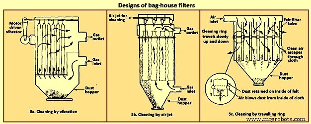
Fig 5 Designs of bag house filters
The fabric filtration process consists of three phases. First, particles collect on individual fibers by the above described mechanisms. Then an intermediate stage exists during which particles accumulate on previously collected particles, bridging the fibers. Finally, the collected particles form a cake in the form of a dust layer which acts as a packed bed filter for the incoming particles. As the dust layer accumulates, the pressure drop across the filter increases, and periodically the dust layer is to be dislodged into the hopper at the bottom to ‘regenerate’ the fabric bag. High efficiencies are attainable with fabric filters, particularly in treating combustion gases from the technological processes. To the extent that effective operation of an ESP depends on the presence of SO2 in the gas as an ionizable species, fabric filters can operate with no loss of efficiency with low-sulphur level.
Fabric filters consist of semi-permeable woven or felted materials which constitute a support for the particles to be removed. A brand-new woven filter cloth has fibers roughly 100 micrometers to 150 micrometers in diameter with open spaces between the fibers of 50 micrometers to 75 micrometers. Initially, the collection efficiency of such a cloth is low because most of the particles pass directly through the fabric. However, deposited particles quickly accumulate, and it is the deposited particle layer that enables the high-efficiency removal once a uniform surface layer has been established.
Although fiber mat filters are similar in some respects to fabric filters, they do not depend on the layer of accumulated particles for high efficiency. Fiber mat filters generally are not cleaned but are discarded. They are ordinarily used when particle concentrations are low, so that reasonable service life can be achieved before discarding.
In a fabric filter the particle layer performs the removal task. As the layer of collected particles grows in thickness, there is an increase in the pressure drop across the particle layer and the underlying fabric. The two major considerations in the design of a fabric filter assembly are the collection efficiency and the pressure drop as a function of time of operation (since the last cleaning). The collection efficiency depends on the local gas velocity and the particle loading on the fabric.
Fabric filters offer the several advantages such as (i) they can achieve very high collection efficiencies even for very small particles, (ii) they can be used for a wide variety of particles, (iii) they can operate over a wide range of volumetric flow rates, and (iv) they need only moderate pressure drops. The limitations of fabric filters are namely (i) operation is to be carried out at temperatures lower than that at which the fabric is destroyed, or its life is shortened to an uneconomical degree, (ii) gas or particle constituents which attack the fabric or prevent proper cleaning, such as sticky particles difficult to dislodge, are to be avoided, and (iii) bag houses need large floor areas. The advantages of fabric filter bag houses clearly outweigh their limitations.
Wet collectors
Wet collectors, or scrubbers, employ water washing to remove particles directly from a gas stream. Scrubbers can be grouped broadly into two main classes namely (i) those in which an array of liquid drops (sprays) form the collecting medium, and (ii) those in which wetted surfaces of various types constitute the collecting medium. The first class includes spray towers and venturi scrubbers, while the second includes plate and packed towers.
Scrubbing is a very effective means of removing small particles from a gas. Removal of particles results from collisions between particles and water drops. In the humid environment of a scrubber, small, dry particles also grow in size by condensation of water and thereby become easier to remove. Re-entrainment of particles is avoided since the particles become trapped in droplets or in a liquid layer. A scrubber also provides the possibility of simultaneously removing soluble gaseous pollutants. The particle-laden scrubbing liquid is to be disposed of, a problem not encountered in dry methods of gas cleaning.
A spray scrubber is a device in which a liquid stream is broken into drops, approximately in the range 0.1 mm to 1 mm in diameter, and introduced into the particle laden gas stream. The array of moving drops becomes a set of targets for collection of the particles in the gas stream. Collection efficiency is computed by considering the efficiency of a single spherical collector and then summing over the number of drops per unit volume of gas flow. The relative motion between the drops and particles is an important factor in the collection efficiency since capture occurs by impaction and direct interception. Diffusion is also important for smaller particles.
There are two general types of spray scrubbers. The first class comprises those having a preformed spray where drops are formed by atomizer nozzles and sprayed into the gas stream. These include (i) counter-current gravity tower, where drops settle vertically against the rising gas stream, (ii) cross-current tower, where drops settle through a horizontal gas stream, and (iii) co-current tower, where spray is horizontal into a horizontal gas stream.
The second class comprises those in which the liquid is atomized by the gas stream itself. Liquid is introduced more or less in bulk into a high-velocity gas flow which shatters the liquid into drops. Devices in this class are called venturi scrubbers since the high velocity gas flow is achieved in a venturi (a contraction). Fig 6 shows four types of wet collection equipment.
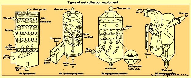
Fig 6 Types of wet collection equipment
The simplest type of wet collector is a spray tower into which water is introduced by means of spray nozzles (Fig 6a). Gas flow in a spray chamber is counter-current to the liquid, the configuration leading to maximum efficiency. Collection efficiency can be improved over the simple spray chamber with the use of a cyclonic spray tower, as shown in Fig 6b. The liquid spray is directed outward from nozzles in a central pipe. An unsprayed section above the nozzles is provided so that the liquid drops with the collected particles have time to reach the walls of the chamber before exit of the gas. An impingement plate scrubber, as shown in Fig 6c, consists of a tower containing layers of baffled plates with holes (5,000 to 50,000 per square meter) through which the gas must rise and over which the water must fall. Highest collection efficiencies of wet collectors are obtained in a venturi scrubber, shown in Fig 6d, in which water is introduced at right angles to a high-velocity gas flow in a venturi tube, resulting in the formation of very small water droplets by the flow and high relative velocities of water and particles. The high gas velocity is responsible for the breakup of the liquid. Aside from the small droplet size and high impingement velocities, collection is enhanced through particle growth by condensation. Different types of particle scrubbing devices are described below.
Plate scrubber – It is a vertical tower containing one or more horizontal plates (trays). Gas enters the bottom of the tower and must pass through perforations in each plate as the gas flows counter-current to the descending water stream. Plate scrubbers are normally named for the type of plates they contain (e.g. sieve plate tower). Collection efficiency increases as the diameter of the perforations decreases. A cut diameter, that collects with 50 % efficiency, of around 1 micrometer aerodynamic diameter can be achieved with 3.2 mm diameter holes in a sieve plate.
Packed-bed scrubber – It operates similarly to packed-bed gas absorber. Collection efficiency increases as packing size decreases. A cut diameter of 1.5 micrometers aerodynamic diameter can be attained in columns packed with 2.5 cm elements.
Spray scrubber – In this scrubber, particles are collected by liquid drops which have been atomized by spray nozzles. Horizontal and vertical gas flows are used, as well as spray introduced co-current, counter-current, or cross-flow to the gas. Collection efficiency depends on droplet size, gas velocity, liquid / gas ratio, and droplet trajectories. For droplets falling at their terminal velocity, the optimum droplet diameter for fine-particle collection lays in the range 100 micrometers to 500 micrometers. Gravitational settling scrubbers can achieve cut diameters of around 2 micrometers. The liquid / gas ratio is in the range 0.001 cum to 0.01 cum per cum of gas treated.
Venturi scrubber – A moving gas stream is used to atomize liquids into droplets. High gas velocities (60 m/sec to 120 m/s) lead to high relative velocities between gas and particles and promote collection.
Cyclone scrubber – Drops can be introduced into the gas stream of a cyclone to collect particles. The spray can be directed outward from a central manifold or inward from the collector wall.
Baffle scrubber – In this scrubber, there are changes in gas flow velocity and direction induced by solid surfaces.
Impingement-entrainment scrubber – The gas is forced to impinge on a liquid surface to reach a gas exit. Some of the liquid atomizes into drops which are entrained by the gas. The gas exit is designed so as to minimize the loss of entrained droplets.
Fluidized-bed scrubber – A zone of fluidized packing is provided where gas and liquid can mix intimately. Gas passes upward through the packing, while liquid is sprayed up from the bottom and / or flows down over the top of the fluidized layer of packing.
The collection efficiency of wet collectors can be related to the total energy loss in the equipment. The higher is the scrubber power per unit volume of gas treated, the better is the collection efficiency. Almost all the energy is introduced in the gas, and thus the energy loss can be measured by the pressure drop of gas through the unit. The major advantage of wet collectors is the wide variety of types, allowing the selection of a unit suitable to the particular removal problem. As regards disadvantages, high pressure drops (and hence energy requirements) are to be maintained, and the handling and disposal of large volumes of scrubbing liquid are to be undertaken.
In case of spray scrubbing, the conceptually simplest of the devices is a gravity spray chamber. Water droplets are introduced at the top of an empty chamber through atomizing nozzles and fall freely at their terminal settling velocities counter-currently through the rising gas stream. The particle-containing liquid collects in a pool at the bottom and is to be pumped out for treatment to remove the solids, and the cleaned liquid is normally recycled to the tower. The overall efficiency of a spray tower increases as the collection efficiency of a single drop increases, as the length of the chamber increases, and as the ratio of the volumetric flow rate of water to that of gas increases. It increases as the diameter of the drops decreases.
Venturi scrubbers are used when high collection efficiencies are needed and when most of the particles are smaller than 2 micrometers in diameter. There are a number of examples, in fact, where a venturi scrubber is the only practical device for a gas-cleaning application. If the particles to be removed are sticky, flammable, or highly corrosive, for example, ESPs and fabric filters cannot be used. Venturi scrubbers are also the only high-efficiency particulate collectors which can simultaneously remove gaseous species from the effluent stream.
The distinguishing feature of a venturi scrubber is a constricted cross section or throat through which the gas is forced to flow at high velocity. A typical venturi scrubber configuration is shown in Fig 7. The configuration includes a converging conical section where the gas is accelerated to throat velocity, a cylindrical throat, and a conical expander where the gas is slowed down. Liquid can be introduced either through tangential holes in the inlet cone or in the throat itself. In the former case, the liquid enters the venturi as a film on the wall and flows down the wall to the throat, where it is atomized by the high-velocity gas stream. In the latter, the liquid is injected perpendicular to the gas flow in the throat, atomized, and then accelerated. Gas velocities in the range 60 m/sec to 120 m/sec are achieved, and the high relative velocity between the particle laden gas flow and the droplets promotes collection. The collection process is essentially complete by the end of the throat. Because they operate at much higher velocities than ESPs precipitators or bag houses, venturi scrubbers are physically smaller and can be economically made of corrosion-resistant materials. Venturis have the simplest configuration of the scrubbers and are the smallest in size. Fig 7 shows the comparison of the efficiency of venturi scrubber with the efficiencies of other gas cleaning devices.
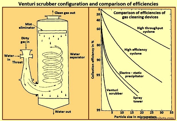
Fig 7 Venturi scrubber configuration and comparison of efficiencies
A typical range of liquid to gas flow rate ratios for a venturi scrubber is 0.001 cum to 0.003 cum of liquid per cum of gas. At the higher liquid / gas ratios, the gas velocity at a given pressure drop is reduced, and at lower ratios, the velocity is increased. For gas flow rates exceeding about 1,000 cum / minute venturi scrubbers are normally constructed in a rectangular configuration in order to maintain an equal distribution of liquid over the throat area.
製造プロセス