


複数のNRF24L01モジュールを備えたArduinoワイヤレスネットワーク
このチュートリアルでは、複数のNR24L01トランシーバモジュールで構成されるArduinoワイヤレスネットワークを構築する方法を学習します。次のビデオを見るか、以下のチュートリアルを読むことができます。
例として、5つのノードのネットワークを作成しました。各ノードは、ネットワーク内の任意のノードと通信でき、同時に送信機と受信機の両方として機能できます。この例は、実際には、はるかに大規模なネットワークを作成する方法を説明する方法で設定されています。正確には、1つのRFチャネルで合計3125のモジュールが相互に通信できます。それでは、それがどのように機能するかを見てみましょう。
以前のチュートリアルでは、NRF24L01モジュールとRF24ライブラリを使用して2つのArduinoボード間でワイヤレス通信を行う方法をすでに学びました。このライブラリに加えて、RF24Networkライブラリを使用します。これにより、多数のボードが相互に通信するArduinoワイヤレスネットワークを簡単に構築できます。ネットワークトポロジの仕組みは次のとおりです。
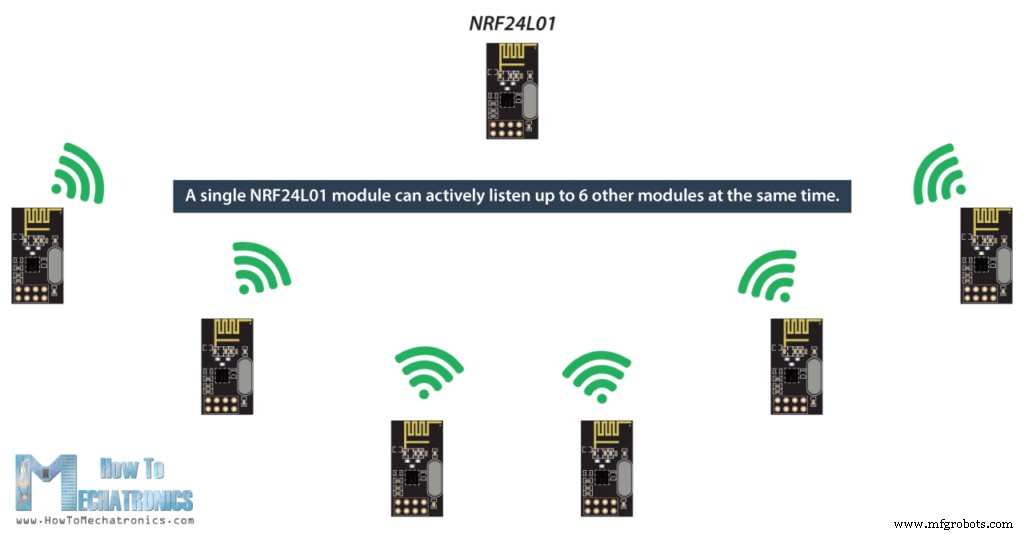
1つのNRF24L01モジュールは、同時に最大6つの他のモジュールをアクティブにリッスンできます。
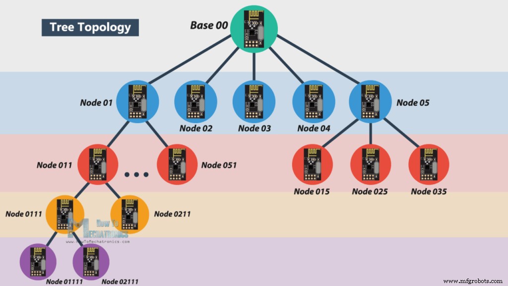
この機能は、RF24Networkライブラリによって利用され、ツリートポロジに配置されたネットワークを生成します。この場合、1つのノードがベースであり、他のすべてのノードはそのノードまたは別のノードの子です。各ノードには最大5つの子を含めることができ、これは5レベルの深さになる可能性があります。つまり、合計3125ノードのネットワークを作成できます。各ノードは、ツリー内のノードの位置を正確に表す15ビットのアドレスで定義する必要があります。
実際には、ノードのアドレスを8進形式で定義できます。したがって、マスターまたはベースのアドレスは00、ベースの子アドレスは01から05、01ノードの子アドレスは011から051などです。
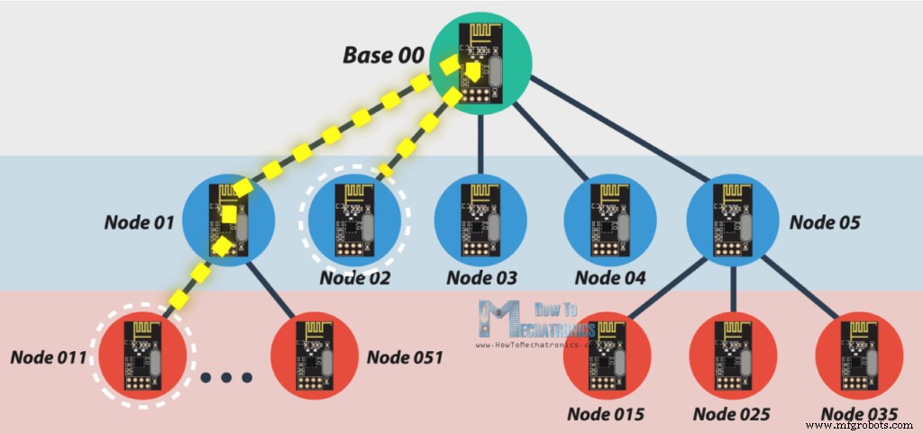
ノード011がノード02と通信する場合、通信はノード01とベースノード00を経由する必要があるため、通信を成功させるには、これら2つのノードが常にアクティブである必要があります。
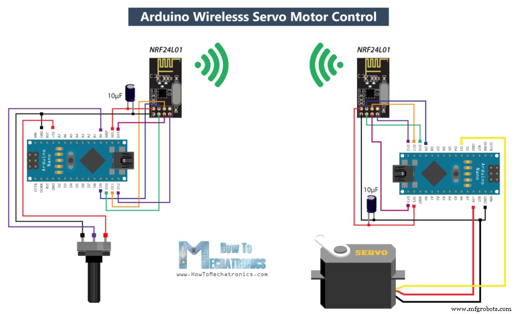
このチュートリアルの主な例を説明する前に、ライブラリがどのように機能するかをよりよく理解するために、2つのArduinoボードが相互に通信する簡単な例を作成しましょう。この例の回路図は次のとおりです。
このArduinoチュートリアルに必要なコンポーネントは、以下のリンクから入手できます。
したがって、最初のArduinoでポテンショメータを使用して、2番目のArduinoでサーボモーターを制御します。ここでソースコードを見てみましょう。
ポテンショメータ側のコードは次のとおりです。
まず、ライブラリRF24とRF24Networkの両方、およびSPIライブラリを含める必要があります。次に、RF24オブジェクトを作成し、それをRF24Networkオブジェクトに含める必要があります。ここでは、ノードのアドレスを8進数形式で定義する必要があります。このノードの場合は00、サーボ側の他のノードの場合は01です。
セットアップセクションでは、このノードのチャネルとアドレスを設定して、ネットワークを初期化する必要があります。
ループセクションでは、ネットワーク内のすべてのアクションが発生するupdate()関数を常に呼び出す必要があります。次に、ポテンショメータの値を読み取り、サーボ制御に適した0〜180の値に変換します。次に、データが送信されるノードのアドレスを割り当てるネットワークヘッダーを作成します。最後に、write()関数を使用して、データを他のノードに送信します。したがって、ここで最初のパラメーターにはアドレス情報が含まれ、2番目のパラメーターはデータが送信されるポイントを示し、3番目のパラメーターはデータのサイズです。
サーボ側のコードは次のとおりです。
一方、サーボモーターでは、前に説明したのと同じ方法でライブラリとオブジェクトを定義する必要があります。ここで、8進形式のこのノードのアドレスは01です。サーボモーターを定義した後、ループセクションで、while()ループとavailable()関数を使用して、着信データがあるかどうかを常にチェックします。 trueの場合、データが受け入れられるネットワークヘッダーと、データが格納される変数を作成します。次に、read()関数を使用してデータを読み取り、incomingData変数に格納します。最後に、このデータを使用して、他のノードからのポテンショメータに従ってサーボモーターを移動します。
この例を理解した後、このチュートリアルのメインの例に進み、相互に通信する5つのArduinoのワイヤレスネットワークを構築できます。これが例のブロック図です。
したがって、ベースから、ポテンショメータを使用してノード01でサーボモーターを制御し、2番目のポテンショメータでノード022でLEDを制御し、ボタンを使用してノード012でLEDを制御し、ここでLEDを制御します。ベースはノード02のポテンショメータを使用して制御されます。ノード012の赤外線センサーも使用してノード01のLEDを制御します。したがって、この例では、データの送信と受信の両方を同時に行う方法を説明していることがわかります。また、さまざまなブランチのノードと通信する方法についても説明します。 Arduinoコードを見てみましょう。
関連:DIYArduinoRC送信機
したがって、ベースノードまたはマスターノードでは、前に説明したようにライブラリとオブジェクトを定義し、マスターがデータを送信する他のすべてのノードも定義する必要があります。ループセクションでは、着信データがあるかどうかを常にチェックすることから始めます。その場合、データを読み取り、incomingData変数に格納し、それを使用してLEDの明るさを制御します。このデータは、実際にはノード02のポテンショメータからのものです。そのコードを見ると、セットアップがほとんど同じであることがわかります。重要なのは、データを送信する場所に正しいアドレスを割り当てることです。この場合、それはマスター00です。したがって、ポテンショメータの値を読み取り、それを0〜255の適切なPWM値に変換した後、このデータをマスターに送信します。ここで、millis()関数を使用して10ミリ秒間隔でデータを送信していることがわかります。
次に、マスターから、サーボモーターを制御するためにポテンショメーターデータをノード01に送信します。
ノード01は、実際には2つの異なるノードからデータを受信しています。1つはサーボ制御用で、もう1つはノード012の赤外線センサーからのLED制御用です。
このような場合、データの取得元のノードから情報を取得するために、header.from_node属性を使用します。着信データがマスターからのものである場合は、それを使用してサーボを制御し、着信データがノード012からのものである場合は、それを使用してLEDを制御します。
ノード012には、送信と受信の両方があります。赤外線センサーはノード01で前述のLEDを制御し、ここでのLEDはマスターのボタンから制御します。
最後に、ノード022のLEDは、マスターの他のポテンショメータからのデータを使用して制御されます。
つまり、すべてが適切に接続され、すべてのノードが常にアクティブである場合、私たちの仕事はノードを正確にアドレス指定することになり、背後にあるすべての重い作業は、信じられないほどのRF24Networkライブラリによって実行されます。
以上で、このArduinoプロジェクトを楽しんで、何か新しいことを学んだことを願っています。以下のコメントセクションでお気軽に質問してください。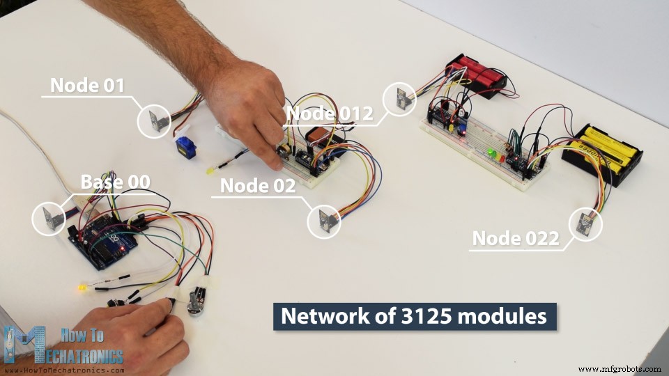
RF24Networkライブラリを使用したArduinoワイヤレスサーボモーター制御
/*
  Arduino Wireless Network - Multiple NRF24L01 Tutorial
 == Example 01 - Servo Control / Node 00 - Potentiometer ==
  by Dejan, www.HowToMechatronics.com
  Libraries:
  nRF24/RF24, https://github.com/nRF24/RF24
  nRF24/RF24Network, https://github.com/nRF24/RF24Network
*/
#include <RF24.h>
#include <RF24Network.h>
#include <SPI.h>

RF24 radio(10, 9);               // nRF24L01 (CE,CSN)
RF24Network network(radio);      // Include the radio in the network
const uint16_t this_node = 00;   // Address of this node in Octal format ( 04,031, etc)
const uint16_t node01 = 01;

void setup() {
  SPI.begin();
  radio.begin();
  network.begin(90, this_node);  //(channel, node address)
}

void loop() {
  network.update();
  unsigned long potValue = analogRead(A0);  // Read the potentiometer value
  unsigned long angleValue = map(potValue, 0, 1023, 0, 180); // Convert the value to 0-180
  RF24NetworkHeader header(node01);     // (Address where the data is going)
  bool ok = network.write(header, &angleValue, sizeof(angleValue)); // Send the data
}Code language: Arduino (arduino)/*
Arduino Wireless Network - Multiple NRF24L01 Tutorial
== Example 01 - Servo Control / Node 01 - Servo motor ==
*/
#include <RF24.h>
#include <RF24Network.h>
#include <SPI.h>
#include <Servo.h>
RF24 radio(10, 9); // nRF24L01 (CE,CSN)
RF24Network network(radio); // Include the radio in the network
const uint16_t this_node = 01; // Address of our node in Octal format ( 04,031, etc)
Servo myservo; // create servo object to control a servo
void setup() {
SPI.begin();
radio.begin();
network.begin(90, this_node); //(channel, node address)
myservo.attach(3); // (servo pin)
}
void loop() {
network.update();
while ( network.available() ) { // Is there any incoming data?
RF24NetworkHeader header;
unsigned long incomingData;
network.read(header, &incomingData, sizeof(incomingData)); // Read the incoming data
myservo.write(incomingData); // tell servo to go to a particular angle
}
}Code language: Arduino (arduino)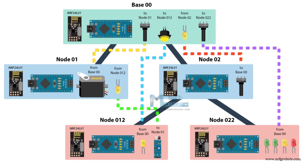
/*
  Arduino Wireless Network - Multiple NRF24L01 Tutorial
          == Base/ Master Node 00==
  by Dejan, www.HowToMechatronics.com
  Libraries:
  nRF24/RF24, https://github.com/nRF24/RF24
  nRF24/RF24Network, https://github.com/nRF24/RF24Network
*/

#include <RF24Network.h>
#include <RF24.h>
#include <SPI.h>

#define button 2
#define led 3

RF24 radio(10, 9);               // nRF24L01 (CE,CSN)
RF24Network network(radio);      // Include the radio in the network
const uint16_t this_node = 00;   // Address of this node in Octal format ( 04,031, etc)
const uint16_t node01 = 01;      // Address of the other node in Octal format
const uint16_t node012 = 012;
const uint16_t node022 = 022;

void setup() {
  SPI.begin();
  radio.begin();
  network.begin(90, this_node);  //(channel, node address)
  radio.setDataRate(RF24_2MBPS);
  pinMode(button, INPUT_PULLUP);
  pinMode(led, OUTPUT);
}

void loop() {
  network.update();
  //===== Receiving =====//
  while ( network.available() ) {     // Is there any incoming data?
    RF24NetworkHeader header;
    unsigned long incomingData;
    network.read(header, &incomingData, sizeof(incomingData)); // Read the incoming data
    analogWrite(led, incomingData);    // PWM output to LED 01 (dimming)
  }
  //===== Sending =====//
  // Servo control at Node 01
  unsigned long potValue = analogRead(A0);
  unsigned long angleValue = map(potValue, 0, 1023, 0, 180); // Suitable for servo control
  RF24NetworkHeader header2(node01);     // (Address where the data is going)
  bool ok = network.write(header2, &angleValue, sizeof(angleValue)); // Send the data

  // LED Control at Node 012
  unsigned long buttonState = digitalRead(button);
  RF24NetworkHeader header4(node012);    // (Address where the data is going)
  bool ok3 = network.write(header4, &buttonState, sizeof(buttonState)); // Send the data

  // LEDs control at Node 022
  unsigned long pot2Value = analogRead(A1);
  RF24NetworkHeader header3(node022);    // (Address where the data is going)
  bool ok2 = network.write(header3, &pot2Value, sizeof(pot2Value)); // Send the data
}Code language: Arduino (arduino)/*
Arduino Wireless Network - Multiple NRF24L01 Tutorial
== Node 02 (Child of Master node 00) ==
*/
#include <RF24Network.h>
#include <RF24.h>
#include <SPI.h>
RF24 radio(10, 9); // nRF24L01 (CE,CSN)
RF24Network network(radio); // Include the radio in the network
const uint16_t this_node = 02; // Address of our node in Octal format ( 04,031, etc)
const uint16_t master00 = 00; // Address of the other node in Octal format
const unsigned long interval = 10; //ms // How often to send data to the other unit
unsigned long last_sent; // When did we last send?
void setup() {
SPI.begin();
radio.begin();
network.begin(90, this_node); //(channel, node address)
radio.setDataRate(RF24_2MBPS);
}
void loop() {
network.update();
//===== Sending =====//
unsigned long now = millis();
if (now - last_sent >= interval) { // If it's time to send a data, send it!
last_sent = now;
unsigned long potValue = analogRead(A0);
unsigned long ledBrightness = map(potValue, 0, 1023, 0, 255);
RF24NetworkHeader header(master00); // (Address where the data is going)
bool ok = network.write(header, &ledBrightness, sizeof(ledBrightness)); // Send the data
}
}Code language: Arduino (arduino)/*
Arduino Wireless Network - Multiple NRF24L01 Tutorial
== Node 02 (Child of Master node 00) ==
*/
#include <RF24Network.h>
#include <RF24.h>
#include <SPI.h>
#include <Servo.h>
#define led 2
RF24 radio(10, 9); // nRF24L01 (CE,CSN)
RF24Network network(radio); // Include the radio in the network
const uint16_t this_node = 01; // Address of our node in Octal format ( 04,031, etc)
const uint16_t master00 = 00; // Address of the other node in Octal format
Servo myservo; // create servo object to control a servo
void setup() {
SPI.begin();
radio.begin();
network.begin(90, this_node); //(channel, node address)
radio.setDataRate(RF24_2MBPS);
myservo.attach(3); // (servo pin)
pinMode(led, OUTPUT);
}
void loop() {
network.update();
//===== Receiving =====//
while ( network.available() ) { // Is there any incoming data?
RF24NetworkHeader header;
unsigned long incomingData;
network.read(header, &incomingData, sizeof(incomingData)); // Read the incoming data
if (header.from_node == 0) { // If data comes from Node 02
myservo.write(incomingData); // tell servo to go to a particular angle
}
if (header.from_node == 10) { // If data comes from Node 012
digitalWrite(led, !incomingData); // Turn on or off the LED 02
}
}
}Code language: Arduino (arduino)/*
Arduino Wireless Network - Multiple NRF24L01 Tutorial
== Node 012 (child of Node 02)==
*/
#include <RF24Network.h>
#include <RF24.h>
#include <SPI.h>
#define led 2
#define IR 3
RF24 radio(10, 9); // nRF24L01 (CE,CSN)
RF24Network network(radio); // Include the radio in the network
const uint16_t this_node = 012; // Address of our node in Octal format ( 04,031, etc)
const uint16_t node01 = 01; // Address of the other node in Octal format
void setup() {
SPI.begin();
radio.begin();
network.begin(90, this_node); //(channel, node address)
radio.setDataRate(RF24_2MBPS);
pinMode(led, OUTPUT);
pinMode(IR, INPUT);
}
void loop() {
network.update();
//===== Receiving =====//
while ( network.available() ) { // Is there any incoming data?
RF24NetworkHeader header;
unsigned long buttonState;
network.read(header, &buttonState, sizeof(buttonState)); // Read the incoming data
digitalWrite(led, !buttonState); // Turn on or off the LED
}
//===== Sending =====//
unsigned long irV = digitalRead(IR); // Read IR sensor
RF24NetworkHeader header8(node01);
bool ok = network.write(header8, &irV, sizeof(irV)); // Send the data
}Code language: Arduino (arduino)/*
Arduino Wireless Network - Multiple NRF24L01 Tutorial
== Node 022 (child of Node 02)==
*/
#include <RF24Network.h>
#include <RF24.h>
#include <SPI.h>
#define led1 2
#define led2 3
#define led3 4
#define led4 5
RF24 radio(10, 9); // nRF24L01 (CE,CSN)
RF24Network network(radio); // Include the radio in the network
const uint16_t this_node = 022; // Address of our node in Octal format ( 04,031, etc)
const uint16_t master00 = 00; // Address of the other node in Octal format
void setup() {
SPI.begin();
radio.begin();
network.begin(90, this_node); //(channel, node address)
radio.setDataRate(RF24_2MBPS);
pinMode(led1, OUTPUT);
pinMode(led2, OUTPUT);
pinMode(led3, OUTPUT);
pinMode(led4, OUTPUT);
}
void loop() {
network.update();
//===== Receiving =====//
while ( network.available() ) { // Is there any incoming data?
RF24NetworkHeader header;
unsigned long potValue;
network.read(header, &potValue, sizeof(potValue)); // Read the incoming data
// Turn on the LEDs as depending on the incoming value from the potentiometer
if (potValue > 240) {
digitalWrite(led1, HIGH);
} else {
digitalWrite(led1, LOW);
}
if (potValue > 480) {
digitalWrite(led2, HIGH);
} else {
digitalWrite(led2, LOW);
}
if (potValue > 720) {
digitalWrite(led3, HIGH);
} else {
digitalWrite(led3, LOW);
}
if (potValue > 960) {
digitalWrite(led4, HIGH);
} else {
digitalWrite(led4, LOW);
}
}
}Code language: Arduino (arduino)
製造プロセス