



Arduinoレーダーシステムの製作:超音波センサーとサーボでステップバイステップガイド
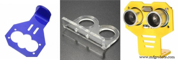
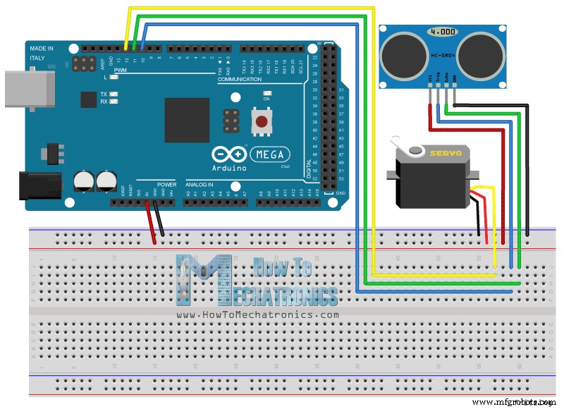
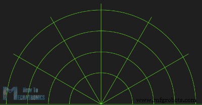
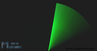
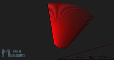
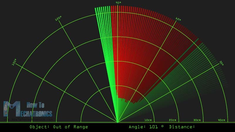
このArduinoチュートリアルでは、ArduinoボードとProcessing開発環境を使ってクールなレーダーを作る方法を紹介します。詳細については以下の動画を見るか、書面チュートリアルをお読みください。 このArduinoプロジェクトに必要なのは、物体検知用の超音波センサー、センサーを回転させる小型ホビーサーボモーター、それらを制御するArduinoボードだけです。[/column] 以下のサイトから入手できます: Banggoodには超音波センサー用の専用マウントブラケットもあります。以下のリンクから入手できます: 超音波センサーHC-SR04をピン10と11、サーボモーターをピン12に接続します。 ArduinoとProcessing IDEの連携を可能にするコードを作成し、Arduinoボードにアップロードします。連携の仕組みについては、私のArduinoとProcessingチュートリアルをご覧ください。 次に、Arduinoボードから角度とセンサー測定距離の値を、SerialEvent()関数を使ってProcessing IDEで受信します。この関数はシリアルポートからデータを読み取り、角度と距離の値をiAngleとiDistance変数に格納します。これらの変数はレーダー、ライン、検知物体、テキストの描画に使用します。 レーダー描画用にdrawRadar()関数を作成しました。これはarc()とline()関数で構成されます。 レーダーに沿って動くライン描画用にdrawLine()関数を作成しました。回転中心はtranslate()関数で設定し、iAngle変数を使ったline()関数で各度ごとにラインを再描画します。 検知物体描画用にdrawObject()関数を作成しました。超音波センサーから距離を取得し、ピクセルに変換して、センサーの角度と組み合わせてレーダー上に物体を描画します。 画面上のテキスト用にdrawText()関数を作成し、特定の位置にテキストを描画します。 これらすべての関数は、繰り返し実行されて画面を描画するメインのdraw()関数で呼び出されます。ここではfill()関数を2パラメータで使って、動くラインのモーションブラーと遅いフェードアウトをシミュレートしています。 レーダーの最終的な外観はこちら: Arduinoレーダーの完全なProcessingソースコードはこちら: size()関数の値をお使いの画面解像度に変更するだけです。概要
このArduinoプロジェクトに必要なコンポーネント
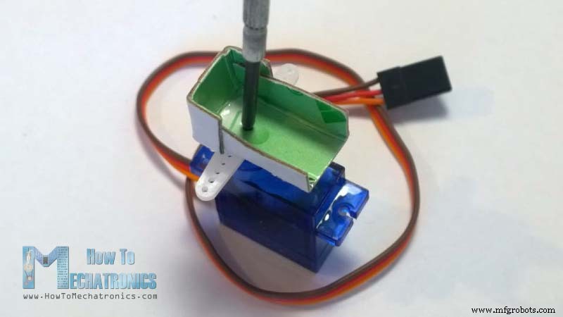
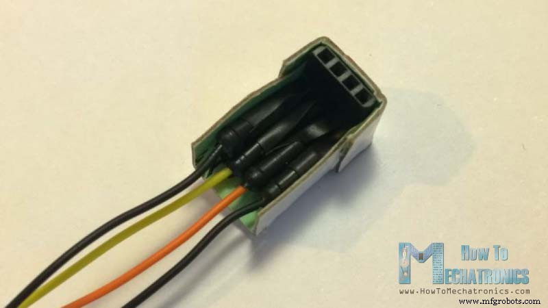
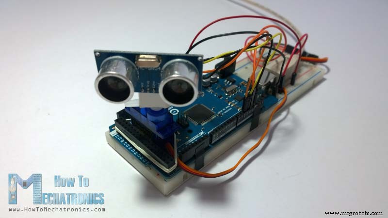
デバイスの組み立て
Arduinoレーダー回路図
ソースコード
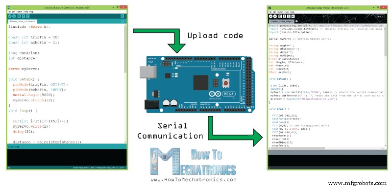
Arduinoソースコード(各行の説明付き):
// Servoライブラリをインクルード
#include <Servo.h>.
// 超音波センサーのTrigとEchoピンを定義
const int trigPin = 10;
const int echoPin = 11;
// 継続時間と距離の変数
long duration;
int distance;
Servo myServo; // サーボ制御用サーボオブジェクト作成
void setup() {
  pinMode(trigPin, OUTPUT); // trigPinを出力に設定
  pinMode(echoPin, INPUT); // echoPinを入力に設定
  Serial.begin(9600);
  myServo.attach(12); // サーボモーターが接続されているピンを定義
}
void loop() {
  // サーボモーターを15度から165度まで回転
  for(int i=15;i<=165;i++){
    myServo.write(i);
    delay(30);
    distance = calculateDistance();// 各角度での超音波センサー測定距離を計算する関数呼び出し
    Serial.print(i); // 現在の角度をシリアルポートに送信
    Serial.print(","); // Processing IDEでのインデックス用に追加文字を送信
    Serial.print(distance); // 距離値をシリアルポートに送信
    Serial.print("."); // Processing IDEでのインデックス用に追加文字を送信
  }
  // 165度から15度まで繰り返し
  for(int i=165;i>15;i--){
    myServo.write(i);
    delay(30);
    distance = calculateDistance();
    Serial.print(i);
    Serial.print(",");
    Serial.print(distance);
    Serial.print(".");
  }
}
// 超音波センサーで測定された距離を計算する関数
int calculateDistance(){
  digitalWrite(trigPin, LOW);
  delayMicroseconds(2);
  // trigPinを10マイクロ秒HIGHに設定
  digitalWrite(trigPin, HIGH);
  delayMicroseconds(10);
  digitalWrite(trigPin, LOW);
  duration = pulseIn(echoPin, HIGH); // echoPinを読み取り、音波往復時間をマイクロ秒で取得
  distance= duration*0.034/2;
  return distance;
}
void drawRadar() {
  pushMatrix();
  translate(960,1000); // 開始座標を新しい位置に移動
  noFill();
  strokeWeight(2);
  stroke(98,245,31); // 弧線を描画
  arc(0,0,1800,1800,PI,TWO_PI);
  arc(0,0,1400,1400,PI,TWO_PI);
  arc(0,0,1000,1000,PI,TWO_PI);
  arc(0,0,600,600,PI,TWO_PI);
  // 角度ラインを描画
  line(-960,0,960,0);
  line(0,0,-960*cos(radians(30)),-960*sin(radians(30)));
  line(0,0,-960*cos(radians(60)),-960*sin(radians(60)));
  line(0,0,-960*cos(radians(90)),-960*sin(radians(90)));
  line(0,0,-960*cos(radians(120)),-960*sin(radians(120)));
  line(0,0,-960*cos(radians(150)),-960*sin(radians(150)));
  line(-960*cos(radians(30)),0,960,0);
  popMatrix();
}
void drawLine() {
  pushMatrix();
  strokeWeight(9);
  stroke(30,250,60);
  translate(960,1000); // 開始座標を新しい位置に移動
  line(0,0,950*cos(radians(iAngle)),-950*sin(radians(iAngle))); // 角度に応じてラインを描画
  popMatrix();
}
void drawObject() {
  pushMatrix();
  translate(960,1000); // 開始座標を新しい位置に移動
  strokeWeight(9);
  stroke(255,10,10); // 赤色
  pixsDistance = iDistance*22.5; // センサー距離をcmからピクセルに変換
  // 範囲を40cmに制限
  if(iDistance<40){
    // 角度と距離に応じて物体を描画
    line(pixsDistance*cos(radians(iAngle)),-pixsDistance*sin(radians(iAngle)),950*cos(radians(iAngle)),-950*sin(radians(iAngle)));
  }
  popMatrix();
}void draw() {
fill(98,245,31);
textFont(orcFont);
// 動くラインのモーションブラーと遅いフェードアウトをシミュレート
noStroke();
fill(0,4);
rect(0, 0, width, 1010);
fill(98,245,31); // 緑色
// レーダー描画用関数を呼び出し
drawRadar();
drawLine();
drawObject();
drawText();
}
import processing.serial.*; // シリアル通信用ライブラリをインポート
import java.awt.event.KeyEvent; // シリアルポートからデータ読み取り用ライブラリをインポート
import java.io.IOException;
Serial myPort; // Serialオブジェクト定義
// 変数定義
String angle="";
String distance="";
String data="";
String noObject;
float pixsDistance;
int iAngle, iDistance;
int index1=0;
int index2=0;
PFont orcFont;
void setup() {
size (1920, 1080);
smooth();
myPort = new Serial(this,"COM4", 9600); // シリアル通信開始
myPort.bufferUntil('.'); // シリアルポートから'.'文字までデータ読み取り。実際には angle,distance を読み取り
orcFont = loadFont("OCRAExtended-30.vlw");
}
void draw() {
  fill(98,245,31);
  textFont(orcFont);
  // 動くラインのモーションブラーと遅いフェードアウトをシミュレート
  noStroke();
  fill(0,4);
  rect(0, 0, width, 1010);
  fill(98,245,31); // 緑色
  // レーダー描画用関数を呼び出し
  drawRadar();
  drawLine();
  drawObject();
  drawText();
}
void serialEvent (Serial myPort) {
// シリアルポートからデータ読み取り開始
// シリアルポートから'.'文字までデータを読み取り、String変数 "data" に格納
data = myPort.readStringUntil('.');
data = data.substring(0,data.length()-1);
index1 = data.indexOf(","); // ','文字を検索し、変数 "index1" に格納
angle= data.substring(0, index1); // 位置"0"からindex1位置までのデータを読み取り、これがArduinoボードがシリアルポートに送信した角度の値
distance= data.substring(index1+1, data.length()); // index1位置からデータ末尾まで読み取り、これが距離の値
// String変数をIntegerに変換
iAngle = int(angle);
iDistance = int(distance);
}
void drawRadar() {
pushMatrix();
translate(960,1000); // 開始座標を新しい位置に移動
noFill();
strokeWeight(2);
stroke(98,245,31); // 弧線を描画
arc(0,0,1800,1800,PI,TWO_PI);
arc(0,0,1400,1400,PI,TWO_PI);
arc(0,0,1000,1000,PI,TWO_PI);
arc(0,0,600,600,PI,TWO_PI);
// 角度ラインを描画
line(-960,0,960,0);
line(0,0,-960*cos(radians(30)),-960*sin(radians(30)));
line(0,0,-960*cos(radians(60)),-960*sin(radians(60)));
line(0,0,-960*cos(radians(90)),-960*sin(radians(90)));
line(0,0,-960*cos(radians(120)),-960*sin(radians(120)));
line(0,0,-960*cos(radians(150)),-960*sin(radians(150)));
line(-960*cos(radians(30)),0,960,0);
popMatrix();
}
void drawObject() {
pushMatrix();
translate(960,1000); // 開始座標を新しい位置に移動
strokeWeight(9);
stroke(255,10,10); // 赤色
pixsDistance = iDistance*22.5; // センサー距離をcmからピクセルに変換
// 範囲を40cmに制限
if(iDistance<40){
// 角度と距離に応じて物体を描画
line(pixsDistance*cos(radians(iAngle)),-pixsDistance*sin(radians(iAngle)),950*cos(radians(iAngle)),-950*sin(radians(iAngle)));
}
popMatrix();
}
void drawLine() {
pushMatrix();
strokeWeight(9);
stroke(30,250,60);
translate(960,1000); // 開始座標を新しい位置に移動
line(0,0,950*cos(radians(iAngle)),-950*sin(radians(iAngle))); // 角度に応じてラインを描画
popMatrix();
}
void drawText() {
// 画面にテキストを描画
pushMatrix();
if(iDistance>40) {
noObject = "Out of Range";
} else {
noObject = "In Range";
}
fill(0,0,0);
noStroke();
rect(0, 1010, width, 1080);
fill(98,245,31);
textSize(25);
text("10cm",1180,990);
text("20cm",1380,990);
text("30cm",1580,990);
text("40cm",1780,990);
textSize(40);
text("Object: " + noObject, 240, 1050);
text("Angle: " + iAngle + " °", 1050, 1050);
text("Distance: ", 1380, 1050);
if(iDistance<40) {
text(" " + iDistance + " cm", 1400, 1050);
}
textSize(25);
fill(98,245,60);
translate(961+960*cos(radians(30)),982-960*sin(radians(30)));
rotate(-radians(-60));
text("30°",0,0);
resetMatrix();
translate(954+960*cos(radians(60)),984-960*sin(radians(60)));
rotate(-radians(-30));
text("60°",0,0);
resetMatrix();
translate(945+960*cos(radians(90)),990-960*sin(radians(90)));
rotate(radians(0));
text("90°",0,0);
resetMatrix();
translate(935+960*cos(radians(120)),1003-960*sin(radians(120)));
rotate(radians(-30));
text("120°",0,0);
resetMatrix();
translate(940+960*cos(radians(150)),1018-960*sin(radians(150)));
rotate(radians(-60));
text("150°",0,0);
popMatrix();
}
あらゆる画面解像度に対応したArduinoレーダーコードの新しいアップデート版:
/* Arduino Radar Project
 *
 * Updated version. Fits any screen resolution!
 * Just change the values in the size() function,
 * with your screen resolution.
 *
 * by Dejan Nedelkovski,
 * www.HowToMechatronics.com
 *
 */
import processing.serial.*; // シリアル通信用ライブラリをインポート
import java.awt.event.KeyEvent; // シリアルポートからデータ読み取り用ライブラリをインポート
import java.io.IOException;
Serial myPort; // Serialオブジェクト定義
// 変数定義
String angle="";
String distance="";
String data="";
String noObject;
float pixsDistance;
int iAngle, iDistance;
int index1=0;
int index2=0;
PFont orcFont;
void setup() {
  size (1920, 1080); // ***CHANGE THIS TO YOUR SCREEN RESOLUTION***
  smooth();
  myPort = new Serial(this,"COM4", 9600); // シリアル通信開始
  myPort.bufferUntil('.'); // シリアルポートから'.'文字までデータ読み取り。実際には angle,distance を読み取り
  orcFont = loadFont("OCRAExtended-30.vlw");
}
void draw() {
  fill(98,245,31);
  textFont(orcFont);
  // 動くラインのモーションブラーと遅いフェードアウトをシミュレート
  noStroke();
  fill(0,4);
  rect(0, 0, width, height-height*0.065);
  fill(98,245,31); // 緑色
  // レーダー描画用関数を呼び出し
  drawRadar();
  drawLine();
  drawObject();
  drawText();
}
void serialEvent (Serial myPort) {
  // シリアルポートからデータ読み取り開始
  // シリアルポートから'.'文字までデータを読み取り、String変数 "data" に格納
  data = myPort.readStringUntil('.');
  data = data.substring(0,data.length()-1);
  index1 = data.indexOf(","); // ','文字を検索し、変数 "index1" に格納
  angle= data.substring(0, index1); // 位置"0"からindex1位置までのデータを読み取り、これがArduinoボードがシリアルポートに送信した角度の値
  distance= data.substring(index1+1, data.length()); // index1位置からデータ末尾まで読み取り、これが距離の値
  // String変数をIntegerに変換
  iAngle = int(angle);
  iDistance = int(distance);
}
void drawRadar() {
  pushMatrix();
  translate(width/2,height-height*0.074); // 開始座標を新しい位置に移動
  noFill();
  strokeWeight(2);
  stroke(98,245,31); // 弧線を描画
  arc(0,0,(width-width*0.0625),(width-width*0.0625),PI,TWO_PI);
  arc(0,0,(width-width*0.27),(width-width*0.27),PI,TWO_PI);
  arc(0,0,(width-width*0.479),(width-width*0.479),PI,TWO_PI);
  arc(0,0,(width-width*0.687),(width-width*0.687),PI,TWO_PI);
  // 角度ラインを描画
  line(-width/2,0,width/2,0);
  line(0,0,(-width/2)*cos(radians(30)),(-width/2)*sin(radians(30)));
  line(0,0,(-width/2)*cos(radians(60)),(-width/2)*sin(radians(60)));
  line(0,0,(-width/2)*cos(radians(90)),(-width/2)*sin(radians(90)));
  line(0,0,(-width/2)*cos(radians(120)),(-width/2)*sin(radians(120)));
  line(0,0,(-width/2)*cos(radians(150)),(-width/2)*sin(radians(150)));
  line((-width/2)*cos(radians(30)),0,width/2,0);
  popMatrix();
}
void drawObject() {
  pushMatrix();
  translate(width/2,height-height*0.074); // 開始座標を新しい位置に移動
  strokeWeight(9);
  stroke(255,10,10); // 赤色
  pixsDistance = iDistance*((height-height*0.1666)*0.025); // センサー距離をcmからピクセルに変換
  // 範囲を40cmに制限
  if(iDistance<40){
    // 角度と距離に応じて物体を描画
    line(pixsDistance*cos(radians(iAngle)),-pixsDistance*sin(radians(iAngle)),(width-width*0.505)*cos(radians(iAngle)),-(width-width*0.505)*sin(radians(iAngle)));
  }
  popMatrix();
}
void drawLine() {
  pushMatrix();
  strokeWeight(9);
  stroke(30,250,60);
  translate(width/2,height-height*0.074); // 開始座標を新しい位置に移動
  line(0,0,(height-height*0.12)*cos(radians(iAngle)),-(height-height*0.12)*sin(radians(iAngle))); // 角度に応じてラインを描画
  popMatrix();
}
void drawText() {
  // 画面にテキストを描画
  pushMatrix();
  if(iDistance>40) {
    noObject = "Out of Range";
  } else {
    noObject = "In Range";
  }
  fill(0,0,0);
  noStroke();
  rect(0, height-height*0.0648, width, height);
  fill(98,245,31);
  textSize(25);
  text("10cm",width-width*0.3854,height-height*0.0833);
  text("20cm",width-width*0.281,height-height*0.0833);
  text("30cm",width-width*0.177,height-height*0.0833);
  text("40cm",width-width*0.0729,height-height*0.0833);
  textSize(40);
  text("Object: " + noObject, width-width*0.875, height-height*0.0277);
  text("Angle: " + iAngle + " °", width-width*0.48, height-height*0.0277);
  text("Distance: ", width-width*0.26, height-height*0.0277);
  if(iDistance<40) {
    text(" " + iDistance + " cm", width-width*0.225, height-height*0.0277);
  }
  textSize(25);
  fill(98,245,60);
  translate((width-width*0.4994)+width/2*cos(radians(30)),(height-height*0.0907)-width/2*sin(radians(30)));
  rotate(-radians(-60));
  text("30°",0,0);
  resetMatrix();
  translate((width-width*0.503)+width/2*cos(radians(60)),(height-height*0.0888)-width/2*sin(radians(60)));
  rotate(-radians(-30));
  text("60°",0,0);
  resetMatrix();
  translate((width-width*0.507)+width/2*cos(radians(90)),(height-height*0.0833)-width/2*sin(radians(90)));
  rotate(radians(0));
  text("90°",0,0);
  resetMatrix();
  translate(width-width*0.513+width/2*cos(radians(120)),(height-height*0.07129)-width/2*sin(radians(120)));
  rotate(radians(-30));
  text("120°",0,0);
  resetMatrix();
  translate((width-width*0.5104)+width/2*cos(radians(150)),(height-height*0.0574)-width/2*sin(radians(150)));
  rotate(radians(-60));
  text("150°",0,0);
  popMatrix();
}
製造プロセス
- Arduinoで作るモニター用Ambilightシステム:没入感アップの自作ガイド
- Arduino UNOとOLEDディスプレイでクラシックPongゲームを自作:ステップバイステップチュートリアル
- ArduinoとHC-SR04で作るサーボ駆動障害物回避ロボット
- Arduinoオーディオ周波数検出器 – 高感度サウンドモジュールで最大音量ピークの周波数を測定
- Arduinoで作る自作デジタルペット「Tamaguino」─ 3Dプリンター製ケース付き完全ガイド
- スマートワイヤレス照明スイッチコントローラー:Arduinoで物理スイッチを遠隔操作
- Arduino三目並べ:MAX7219 LEDマトリクスと段ボールケースで自作
- Arduino Nanoで作るスマートな動体検知水鉄砲
- SparkFun 7セグメントディスプレイで作る信頼性の高いArduinoカウントダウンタイマー
- Arduino向日葵:太陽を追尾する電子ヒマワリの製作
- Arduinoで自作RCポルシェカー:ステップバイステップガイド