


炉内での燃料の燃焼と熱伝達
炉内での燃料の燃焼と熱伝達
炉内の熱は、炉の装入物(炉内で加熱される材料)を加熱するために、そして時には化学反応のために必要とされます。熱エネルギーの3つの源は、(i)燃料の燃焼、(ii)電気エネルギー、および(iii)発熱反応を通じて利用可能な化学エネルギーです。電熱炉を除いて、この熱の要件(化学エネルギーを除く)は、燃料の燃焼によって満たされます。燃料は、ガス状燃料(例えば、コークス炉ガス、ブラストファーネスガス、およびコンバーターガス、天然ガス、および液体石油ガスなどのような副産物ガス)、液体燃料(例えば、燃料油、およびタールなど)であり得る。 、または固体燃料(例:石炭、コークスなど)。
すべての燃料には位置エネルギーが含まれています。燃焼すると、この位置エネルギーは燃焼生成物(POC)に放出されます。燃焼は通常、燃料と酸化剤の間の化学反応からの熱とエネルギーの制御された放出であると考えられています。工業プロセスでの燃焼のほぼすべてが炭化水素燃料を使用します。典型的な炭化水素燃料の一般的な燃焼反応は、燃料+酸化剤=二酸化炭素(CO2)+水蒸気(H2O)+他の種の式で与えられます。 「他の種」は、使用する酸化剤の種類と、燃料と酸化剤の比率によって異なります。最も一般的に使用される酸化剤は空気であり、これは体積でほぼ79%の窒素(N2)で構成され、一般に燃焼プロセスで運ばれます。燃焼が燃料に富んでいる場合、つまり燃料を完全に燃焼させるのに十分な酸素(O2)がない場合、排気ガスには未燃炭化水素が存在し、過剰なO2はほとんどありません。燃焼が燃料希薄の場合、つまり燃料を完全に燃焼させるのに必要な量よりも多くのO2があり、排気ガスに過剰なO2が含まれている場合。
燃料は、炉の燃焼システムの熱伝達に大きな影響を及ぼします。最も重要な特性の1つは、燃料の発熱量です。これは、加熱されている材料の望ましい生産速度を処理するために燃焼される燃料の量を決定するために使用されます。発熱量は、高位発熱量(HHV)または低位発熱量(LHV)のいずれかとして指定されます。
LHVは、液体の水を蒸気に変換するために必要なエネルギーである気化熱を除外します。これは、LHVがすべてのPOCがガス状であると想定していることを意味します。これは通常、ほぼすべての産業用燃焼アプリケーションに当てはまります。燃焼生成物が、すべての水が気体から液体に変換されるのに十分低い温度でプロセスを離れる場合、凝縮熱は、追加のエネルギー源としてプロセスに放出されます。燃料のHHVには、この追加のエネルギーが含まれています。
燃料の組成は、POCの組成と、燃料を燃焼させるために必要な酸化剤の量を決定する上で重要です。燃料の密度は、炉の燃料供給システムを通過する流量と関連するパイプのサイズを決定するために必要です。
排気ガスの組成は、炉内の熱伝達を決定する上で非常に重要です。排気ガス中の未燃炭化水素は、燃料が完全に燃焼しておらず、したがって利用可能な熱のすべてが放出されていないことを示します。排気ガス中の過剰なO2レベルが高い場合は、通常、供給された酸化剤が多すぎることを示しています。過剰な酸化剤は、排気ガスを通して感知可能なエネルギーを運び出します。これもまた、燃料の利用可能な熱の一部が炉の装入物を加熱するために十分に利用されていないことを意味します。酸化剤が空気の場合、燃料で利用可能なエネルギーの大部分は、排気ガスとともに煙道で実行されます。
POCは、熱エネルギーを炉の装入物に伝達して、その温度を必要な値まで上げてから、炉を離れます。臨界プロセス温度でのPOCの顕熱は、炉では利用できません。プロセスの臨界温度が高いほど、POCの顕熱は高くなります。 POCのこの顕熱は、燃料利用の観点から非常に重要です。
工業用燃焼プロセスで使用される酸化剤には、2つの一般的なタイプがあります。プロセスの大部分は、酸化剤として空気を使用します。ただし、高温プロセスの多くは、空気中で利用できるよりも高濃度のO2(約21体積%)を含む酸化剤を使用します。このタイプの燃焼は、O2強化燃焼と呼ばれます。多くの場合、加熱プロセスでの生産速度は、比較的少量のO2濃縮で大幅に増加する可能性があります。
場合によっては、エア/燃料バーナーは、ほとんどまたはまったく変更を加えることなく、最大約30%のO2を含む酸化剤で正常に動作できます。 O2濃度が高くなると、火炎が不安定になったり、火炎温度が高くなりすぎて、空気/燃料条件下で動作するように設計されたバーナーが使用できなくなる可能性があります。より高純度のO2の利点が追加コストを正当化する高温アプリケーションでは、より高純度の酸化剤を使用できます(90%以上のO2)。加熱プロセスは、高純度のO2によって大幅に強化されます。酸化剤の純度は、燃焼システムの熱伝達に大きな影響を及ぼします。
燃焼システムの重要な側面は、酸化剤に対する燃料の比率です。これを指定する方法はたくさんあります。これらについては、ここで簡単に説明します。燃料としてCH4(メタン)を使用するグローバル燃焼反応は、CH4 +(xO2 + yN2)=CO、CO2、H2、H2O、N2、NOx、O2、微量成分と書くことができます。反応の化学量論は、特定の燃焼システムの燃料に対するO2の比率を示します。化学量論を定量化する1つの方法は、酸化剤中の不活性物質が反応に必要ないため、酸化剤中のO2のみを考慮することです。したがって、CH4を燃料と見なすと、空気とのグローバルな単純化された化学量論反応は、CH4 +(2O2 + 7.52N2)=CO2 + 2H2O+7.52N2と書くことができます。この反応では、空気は2O2+7.52N2として表されます。ここでは、1分子のCH4を燃焼させるために2分子のO2が必要なため、化学量論比は2です。
化学量論比を指定するこの方法は、一般に、O2濃縮を組み込んだ燃焼システムに使用されます。これは、燃焼システムに供給されるO2の量が重要であるためです。
実際の炎は一般に、燃料を完全に燃焼させるためにいくらかの過剰なO2を必要とします。これは、燃料と酸化剤の混合が不完全なためです。 CH4の燃料が豊富な燃焼の場合、化学量論比は2未満です。CH4の燃料の少ない燃焼の場合、化学量論比は2より大きくなります。したがって、酸化剤の組成が重要です。酸化剤の組成を指定する一般的な方法は、酸化剤のO2モル分率を計算することです。
多くの産業用燃焼プロセスは、完全燃焼に理論的に必要とされるよりも約3%多いO2で実行されます。これは多くの場合、未燃炭化水素の排出を最小限に抑え、燃料の完全燃焼を確保するために必要な過剰なO2の量です。これは、特に非予混合システムでは、燃料と酸化剤の混合制限が原因である可能性があります。
過剰なO2が多すぎるということは、炉の装入物ではなく、過剰な燃焼用空気の加熱にエネルギーが浪費されていることを意味します。したがって、CO(一酸化炭素)の排出量を少なくするために、十分な量の過剰なO2のみを使用することが望ましい。 3%の過剰なO2を含むCH4の単純化されたグローバル反応の例は、反応CH4 +(2.06O2 + 7.75N2)=CO2 + 2H2O + 0.06O2+7.75N2です。
ほとんどの工業用炎は乱流であり、一般に乱流レイノルズ数(Re)によって決定されます。乱流特性長スケールは通常、コルモゴロフ長と呼ばれます。コルモゴロフの長さは、散逸が発生する寸法を表しています。テイラー長さスケールは、粘性力に対するひずみ速度の比率として定義できます。さまざまな長さを使用して、炎を特徴付けることができます。炎は、(i)しわのある炎、(ii)ひどくしわのある炎、(iii)渦の中の火炎、および(iv)分散反応フロントである可能性があります。無次元のダンケラー数(Da)は、特定のタイプの燃焼反応にとって重要な反応時間のタイプを示します。この数値は、反応時間と流量の比率です。
燃焼特性
工業用途で一般的に使用される通常の燃焼特性は、(i)燃焼生成物の組成、(ii)火炎温度、(iii)利用可能な熱、および(iv)燃焼後の煙道ガス量です。これらは、火炎からの熱伝達を計算する際に重要です。ガスを炉と炉の装入物に排出します。
燃焼製品
燃焼生成物に重大な影響を与える可能性のある多くの変数があります。重要な変数には、酸化剤の組成、混合比、空気と燃料の予熱温度、および燃料の組成が含まれます。これらについては、以下で簡単に説明します。
酸化剤の組成 – CH4燃焼を例にとると、空気によるCH4の化学量論的燃焼は、グローバル方程式CH4 + 2O2 + 7.52N2 =CO2、2H2O、7.52N2、および微量成分で表すことができます。排気ガスの70体積パーセント以上がN2であることがわかります。同様に、化学量論的O2 / CH4燃焼プロセスは、方程式CH4 + 2O2 =CO2、2H2O、および微量種で表すことができます。 N2の除去により、排気ガスの量が大幅に削減されます。一般に、化学量論的なO2強化CH4燃焼プロセスは、式CH4 + 2O2 + xN2 =CO2 + 2H2O +xN2+微量成分で表すことができます。
燃焼反応からの排気生成物の実際の組成は、酸化剤の組成、ガスの温度、および当量比を含むいくつかの要因に依存します。当量比は、化学量論的な燃料/空気比に対する実際の燃料/空気比の比として定義されます。化学量論的燃焼は、反応ですべてのO2が消費され、生成物に分子O2が含まれていない場合に発生します。
断熱プロセスとは、反応中に熱が失われないこと、または完全に断熱されたチャンバー内で反応が発生することを意味します。これは、放射によって炎から熱が失われる実際の燃焼プロセスには当てはまりません。 CH4の断熱平衡燃焼の予測される主要生成物は、酸化剤組成の関数です。
平衡プロセスとは、化学反応が起こるまでに無限の時間がかかること、または反応生成物が化学反応速度によって制限されないことを意味します。しかし、実際の状況では、燃焼反応はほんの一瞬で完了します。さらに、酸化剤からN 2が除去されると、それに応じて排気生成物中のN 2の濃度が減少する。同様に、CO、CO2、H2Oの濃度も上昇します。この断熱プロセスでは、酸化剤に高レベルのO2が含まれるかなりの量のCOが存在します。
ラジカル生成物H、O、およびOHはすべて、酸化剤中のO2とともに増加します。 NO(一酸化窒素)は、最初は増加し、酸化剤中の約60%のO2の後、システムからより多くのN2が除去されるにつれて減少します。酸化剤が純粋なO2の場合、N2が利用できないため、NOは生成されません。 H2の形の未燃燃料とO2の形の未反応の酸化剤も、酸化剤中のO2濃度とともに増加します。このラジカル濃度の増加、COおよびH2の形の未燃燃料、および未反応のO2はすべて、高温で発生する化学的解離によるものです。
実際の火炎温度は、不完全燃焼と火炎からの放射により、断熱平衡火炎温度よりも低くなります。実際の火炎温度は、火炎がその熱をどれだけよく放射するか、および炉の装入物と耐火壁を含む燃焼システムがその放射をどれだけよく吸収するかによって決まります。
高輝度火炎は、一般に、高非発光火炎よりも火炎温度が低くなります。実際の火炎温度は、炉の装入物と壁がより放射吸収性である場合にも低くなります。これは、炉の装入物と壁の温度が低く、放射吸収率が高い場合に発生します。
ガス状の燃焼生成物が炎を離れるとき、それらは通常、燃焼室を通過するときに対流と放射によってより多くの熱を失います。燃焼プロセスの目的は、燃料に含まれる化学エネルギーを炉の装入物に、または場合によっては燃焼室に伝達することです。燃焼プロセスの熱効率が高いほど、燃焼生成物から炉装入物および燃焼室に伝達される熱が多くなります。したがって、排気スタック内のガス温度は、熱効率の高い加熱プロセスにおける火炎内よりもはるかに低いことが望ましい。その後、燃焼生成物の組成はガス温度によって変化します。
混合比 –排気ガス中のO2およびN2濃度は、当量比とともに厳密に減少します。 H2OおよびCO2濃度は、化学量論的条件でピークに達します。これらのガスは両方とも非発光性のガス状放射を生成するため、これは重要です。 H2とCOの形の未燃燃料は、どちらも当量比とともに増加します。すべての燃料が完全に燃焼しているわけではないため、これは利用可能な熱に反映されます。
空気と燃料の予熱温度 –多くの産業用燃焼プロセスでは、熱を回収してプロセスの全体的な熱効率を改善し、運用コストを削減します。回収された熱は通常、流入する燃焼用空気を予熱するために使用され、時には流入する燃料を予熱するために使用されます。空気または燃料のいずれかを予熱すると、燃焼生成物の組成に影響を与えます。 CO2、H2O、およびN2は、化学的な解離により、空気の予熱によって排気ガスがすべて減少します。安全上の考慮事項と燃料供給配管をすすめる可能性があるため、ほとんどの条件下で燃料予熱温度を高くすることは実用的ではなく、推奨されません。一般に、排気ガスの主成分の濃度はわずかに減少し、微量成分の濃度はわずかに増加するだけであることがわかります。これは、燃焼システムに供給される燃焼用空気の質量と比較して、燃料の質量が比較的小さいという事実によるものです。これは、燃焼用空気を予熱することは、特定の予熱温度で燃料を予熱するよりもはるかに大きな影響を与えることを意味します。
燃料組成 –燃焼生成物は、燃料の組成によって異なります。さまざまな運転条件下でのさまざまな燃料の予測燃焼生成物組成を計算できます。使用されている最も一般的なガス燃料は、H2(水素)、CH4、C3H8(プロパン)、およびH2とCH4の混合物です。これらは、産業用途で通常使用される燃料を代表することを目的としています。光度に関しては、H2は非光度の炎を生成し、CH4は低光度の炎を生成し、C3H8はより高い光度の炎を生成します。
火炎温度 –火炎温度は、火炎から炉の装入物への熱伝達を決定する上で重要な変数です。断熱火炎温度は、酸化剤と燃料の組成、混合比、および空気と燃料の予熱温度の影響を受けます。ただし、実際の火炎温度は断熱火炎温度ほど高くはありませんが、傾向は比較可能であり、実際の状態を表しています。
酸化剤と燃料の組成 – N2は火炎温度を下げる希釈剤として機能するため、空気をO2に置き換えると、火炎温度が大幅に上昇します。火炎温度は通常、空気と純粋なO2で変化します。酸化剤中の空気から約60%O2まで火炎温度が急速に上昇します。 O2濃度が高くなると、火炎温度はゆっくりと上昇します。また、燃料組成は火炎温度に強い影響を与えます。 H2とCH4の燃料ブレンドでは、ブレンド中のH2含有量が増加するにつれて温度が上昇します。増加は直線的ではなく、H2のレベルが高くなると急速に増加することに注意することが重要です。 CH4およびC3H8と比較してH2のコストが比較的高いため、多くの産業用途では使用されていません。ただし、炭化水素の用途の多くでは、高H2燃料がよく使用されます。これらの燃料は化学製造プロセスの副産物であるため、産業ガス供給業者からH2を購入するよりもはるかに安価であり、他の購入した燃料を使用するよりも費用対効果が高くなります。
混合比 –ピーク火炎温度は、化学量論的条件で発生します。酸化剤中のO2濃度が低いほど、非化学量論的条件(燃料が豊富または燃料が少ない)で動作することにより、火炎温度が低下します。これは、熱を吸収して全体の温度を下げるN2の濃度が高いためです。化学量論的条件では、すべての燃料を完全に燃焼させるのに十分な酸化剤があります。追加の酸化剤は、火炎から感知可能なエネルギーを吸収し、火炎温度を下げます。ほとんどの実際の火炎では、火炎のピーク温度は、わずかに燃料が少ない状態で発生することがよくあります。これは、すべての燃料を完全に燃焼させるためにわずかに多くのO2が必要な不完全な混合によるものです。ほぼすべての産業用燃焼アプリケーションは、CO排出量を低く抑えるために、燃料の少ない状態で実行されます。したがって、実際のバーナーの設計によっては、火炎温度がピークに近づく可能性があります。これは、熱伝達を最大化するために望ましいことがよくあります。火炎温度を最大化するときに頻繁に遭遇する問題の1つは、NOxがガス温度とともにほぼ指数関数的に増加するため、NOx(N2の酸化物)排出量も最大化されることです。これにより、火炎のピーク火炎温度を下げてNOx排出量を最小限に抑えるための多くの設計コンセプトが生まれました。これは、炎からの熱伝達にも影響します。
酸化剤と燃料の予熱温度 –断熱火炎温度は変化し、空気/CH4およびO2/CH4火炎の酸化剤の予熱温度の関数です。 O2の顕熱の増加は燃料に含まれる化学エネルギーのほんの一部であるため、火炎温度の上昇はO2/CH4火炎の場合は比較的小さいです。空気/CH4火炎の場合、燃焼反応で大量の空気が発生するため、顕熱の増加が非常に大きくなるため、空気の予熱はより劇的な影響を及ぼします。多くの燃料の空気/燃料火炎では、断熱火炎温度が急速に上昇します。
利用可能な熱 –炉の燃焼システムで利用可能な熱は、全体的な熱効率を決定する上で重要であり、したがって、プロセスの熱伝達を計算する際の要因となります。本質的に利用可能な熱が低いシステムで熱伝達を最大化しようとすることはあまり効果的ではありません。利用可能な熱は、燃料の総発熱量から、高温の排気ガスによって燃焼プロセスから実行されるエネルギーを差し引いたものとして定義されます。
炉内の利用可能な総熱(GAH)は、式GAH=燃料の発熱量+反応物の顕熱-POCによって運ばれて炉を出る熱で与えられます。 GAHは、臨界プロセス温度で利用可能な熱を表します。これは、さまざまなタイプの損失のために、特定の機能を実行するために利用できる熱を表すものではありません。さまざまな燃料燃焼システムを比較するための基準として使用できます。
さらに、炉では、プロセスの臨界温度、耐火物のライニングの厚さ、および耐火物の熱伝導率によって支配される熱損失があります。したがって、炉内の正味利用可能熱(NAH)は、式NAH =GAH −熱損失で与えられます。 NAHは、さまざまな炉の製錬/溶解/加熱効率を比較するための基準として使用できます。
炉の開口部、炉壁、または空気浸透によってプロセスから失われる熱は、プロセスに依存するため、理論的に利用可能な熱の計算では考慮されません。理論的に利用可能な熱は、実際のプロセスで炉の装入物によって実際に吸収されるエネルギーの量に比例します。これは、システムの熱効率に直接関係します。したがって、理論的に利用可能な熱は、一般に、排気ガス温度、酸化剤と燃料の組成、混合比、および空気と燃料の予熱温度の関数として熱効率の傾向を示すために使用されます。
利用可能な熱は、排気ガス温度の関数として変化し、排気ガス温度とともに急速に減少し、燃料組成に比較的依存しません。したがって、プロセスの熱効率を最大化するために、排気ガス温度を最小化することが望ましい。これは通常、排気ガスから炉の装入物(および炉の壁)への熱伝達を最大化し、酸化剤および/または燃料を予熱することによって排気ガスの熱の一部を回収することによって行われます。
排気ガスの温度が上昇すると、燃焼システムからより多くのエネルギーが実行され、システムに残るエネルギーは少なくなります。利用可能な熱は、ガスから熱が失われない断熱平衡火炎温度でゼロに減少します。 CH4 / O2燃焼システムの利用可能な熱は、約2000℃の排気ガス温度でも、利用可能な熱は57%のままです。また、通常、高温加熱および溶融プロセスにCH4/空気システムを使用することはあまり経済的ではありません。約1300℃の排気温度で、CH4 /空気システムに利用可能な熱はわずか30%強です。予熱された空気の形での熱回収は、一般に、炉の熱効率を高めるための高温加熱プロセスに使用されます。
排気ガスの温度が上昇すると、排気ガスでより多くのエネルギーが実行されるため、利用可能な熱が減少します。酸化剤中のO2濃度が空気中の21%から増加するにつれて、利用可能な熱が最初に急速に増加します。これが、効率の段階的な向上が非常に重要であるため、O2濃縮が一般的な手法である理由の1つです。 CH4 /空気システムの熱効率は、空気が約1100℃に予熱された場合の2倍です。
CH4 / O2システムの場合、O2を予熱することによる効率の向上はそれほど劇的ではありません。これは、予熱なしの初期効率がすでに70%であり、O2の質量が、燃料/空気システム内の空気の質量と比較して、燃焼反応においてそれほど重要ではないためです。パイプライン、熱回収装置、およびバーナーを介して高温のO2を流す場合にも、安全上の懸念があります。特定のテクノロジーの燃料節約量は、利用可能な熱曲線を使用して計算できます。
排気ガスの量 –炉の燃焼室を通過するガスの流量は、炉の装入物への対流熱伝達に比例します。この流量に影響を与えるいくつかの要因があります。 1つは、ガスの熱膨張により、高温のガスの実際の流量(1時間あたりの立方メートル)が高くなるため、ガスの温度です。これは、通常は火炎温度を上昇させる燃料または酸化剤を予熱すると、実際の流量が高くなることを意味します。ただし、標準の温度と圧力の条件(STP)に補正した場合、ガスの流量は同じです。
燃焼システムを通るガス流量に非常に強い影響を与える別の要因は、酸化剤の組成です。 O2強化燃焼は、基本的に酸化剤からN2を除去することを含みます。空気/燃料燃焼と比較した主な変化は、煙道ガス量の減少です。これは、燃料の単位体積ごとに、空気/燃料燃焼の10.5体積と比較して、O2/燃料燃焼の場合に3つの正規化された体積のガスが生成されることを意味します。この減少にはプラスとマイナスの両方の効果がありますが、対流熱伝達への影響は、炉室を通過する平均ガス速度の減少と、その結果としての炉チャージへの対流熱伝達の減少です。
排気ガス輸送特性
炉内のガス状成分の輸送特性は、熱伝達と流体力学を決定するために重要です。特性は、温度とガス成分に大きく依存します。工業炉チャンバー内の熱伝達に重要なガス特性は、燃料と酸化剤の組成、混合比、および空気予熱温度の関数によって異なります。燃料の予熱温度の関数としての特性の変化は、最小限の影響しか与えません。非発光ガス放射を計算するには、ガスの組成と温度が必要です。ガス輸送特性は、対流熱伝達係数を計算するために必要です。これは、多くの場合、ヌセルト数(Nu)の形式で与えられます。 Nuは、プラントル数(Pr)とレイノルズ数(Re)から計算されます。次に、対流熱伝達係数「h」は、Nu =hd / kを使用してヌセルト数から計算されます。ここで、dはフローシステムの特性寸法、kは流体の熱伝導率です。 Nu、Pr、およびReの数値を計算するには、ガスの特性が必要です。
密度 –ガス密度を使用して、対流熱伝達係数を計算するために一般的に必要となるレイノルズ数を計算できます。密度は、炉室を通過する平均ガス速度の計算にも使用されます。これは、通常、対流係数の計算にも必要です。ガス密度はガス温度に反比例するため、温度が上昇すると密度は低下します。ガス密度の低下は、絶対ガス温度の逆数にほぼ比例します。また、酸化剤中のO2含有量が増加すると、ガス密度は急速に減少します。これは、火炎温度が上昇したためです。他のすべての変数が同じままである場合、ガス密度が低いということは、Re数が少ないことを意味し、したがって対流熱伝達が減少します。ただし、ガスの質量流量も減少しています。したがって、平均ガス速度は、低密度と低質量流量の複合効果の結果として大きな影響を受けないため、ガス速度による対流への影響は最小限に抑えられます。
ガス密度は、中間の当量比で最小に達します。これもまた、断熱平衡火炎温度に起因する可能性があります。さらに、ガス密度は、空気予熱温度が上昇するにつれてほぼ直線的に減少し、これは火炎温度の曲線と逆相関します。また、ガス密度は、一般的に本能的に予想されるように、ガス混合物の組成の関数として直線的に減少することはありません。この場合も、密度は断熱火炎温度に反比例します。
比熱 –ガス比熱は、ガス熱容量と呼ばれることもあり、炉システム内の対流熱伝達に影響を与えるもう1つの輸送特性です。これは、対流熱伝達係数の計算によく使用されるPr数の計算に使用されます。排気ガスの比熱は、排気ガスの温度に対して非線形に増加します。比熱は、高温になるほど急速に増加します。さらに、酸化剤中のO 2パーセントが増加するにつれて、排気ガスの比熱はほぼ直線的に増加する。他のすべての条件は同じですが、これにより、燃焼生成ガスから炉内への対流熱伝達が改善されます。
ただし、比熱と当量比の間には、燃料への強い依存性など、はるかに複雑な関係があります。すべての燃料は、当量比が増加するにつれて比熱の初期増加を示し、化学量論的条件で極大に達します。化学量論的条件を超えると、比熱は減少し、プラトーになり、再び増加します。 CH4の場合、比熱は高い当量値で非常に急速に増加します。比熱と当量比の関係はかなり複雑ですが、実際には、ほとんどの産業用燃焼プロセスは、当量比と比熱の間に強いがより線形の関係があるわずかに燃料の少ない条件で動作します。 H2 / CH4燃料ブレンドの場合、燃料ブレンドのH2含有量が高いと、比熱が急速に増加します。火炎温度は、ブレンドのH2含有量と非常によく似た関係を示しています。
熱伝導率 –比熱と同様に、ガスの熱伝導率はPr数に影響を与え、Pr数は対流熱伝達係数に影響を与えます。この場合、熱伝導率とPr数の間には反比例の関係があります。他のすべての変数が一定であると仮定すると、熱伝導率が増加(減少)すると、Pr数は対流係数とともに減少(増加)します。ガスの熱伝導率は、絶対温度の平方根に大きく依存します。比熱の場合と同様に、ガス温度でも熱伝導率が非線形に増加します。
さらに、酸化剤中のO 2含有量が増加するにつれて、熱伝導率は急速に増加する。この関係はほぼ線形ですが、酸化剤のO2含有量が多い場合と比較して、O2含有量が少ない場合の方が速く増加します。ただし、輸送特性と当量比には複雑な関係があります。化学量論的条件では極大値があります。 H2の場合、極大値は、広範囲の当量比の全体的な最大値でもあります。 CH4の場合、非常に燃料が豊富な条件(高い当量比)で熱伝導率が急速に増加し、化学量論的条件で伝導率が局所的な最大値を超えます。それほど劇的ではありませんが、C3H8にも同様の現象があります。ほとんどの工業プロセスはわずかに燃料が少ない状態で実行されますが、化学量論的条件の燃料が少ない側では熱伝導率が急速に変化します。
導電率と燃焼用空気予熱温度の間には、はるかに単純な関係が存在します。予熱温度が上昇すると、導電率は直線よりもわずかに速く増加します。また、H2 / CH4燃料ブレンドのH2含有量が増加すると、熱伝導率ははるかに急速に増加します。
粘度 – The absolute or dynamic viscosity is a measure of momentum diffusion. Gas viscosity is having a similar relationship to the thermal conductivity. The viscosity is important in calculating both the Pr and Re numbers, but in opposite ways. As the gas viscosity increases (decreases), the Pr number increases (decreases) and the Re number decreases (increases) assuming that all the other variables are constant. The kinematic viscosity is related to the dynamic viscosity.
There is a nearly linear increase in gas viscosity with the exhaust product temperature. The gas viscosity increases as the O2 content in the oxidizer increases, similar to the adiabatic flame temperature. The gas viscosity peaks at an equivalence ratio of 1.0 (stoichiometric conditions) and declines as the mixture becomes either more fuel rich or more fuel lean. The gas viscosity also increases with the air preheat temperature, comparable to the flame temperature. The viscosity increases as the H2 content increases in an H2/CH4 fuel blend. The increase in the viscosity is more rapid at higher H2 contents.
Pr number – The Pr number is frequently used to calculate the convection heat transfer coefficient. The components of Pr include the specific heat, viscosity, and thermal conductivity. The combination of these variables which forms the Pr number changes as functions of the fuel and oxidizer compositions, the mixing ratio, and the air preheat temperature. However, there is little change in Pr number as a function of the fuel preheat-temperature. The Pr number decreases as a function of temperature, but in a non-uniform way. Initially, it decreases moderately quickly, then decreases more slowly, and finally decreases rapidly at higher temperatures.
There is also a highly nonlinear relationship between the Pr number and the oxidizer composition. For CH4 and C3H8, the Pr number decreases rapidly at first and then levels off at higher O2 contents. For H2, the Pr number actually has a minimum at around 50 % O2 content. Also, a highly nonlinear relationship exists between the Pr number and the equivalence ratio. Most of the fuels show local maximum and minimum. The Pr number also declines almost linearly with the air preheat temperature. The Pr number declines as the H2 content in an H2/CH4 fuel blend decreases, and decreases rapidly at high H2 contents.
Lewis number – The Lewis number (Le) is the ratio of the thermal diffusivity to the molecular (mass) diffusivity. The Le number is important for the heat transfer in combustion systems. In general, for Le values greater than 1, there are some enhancements in convective heat transfer due to chemical recombination reactions. The Le number is 1 for temperatures below 1200 deg C, depending on the fuel, and then rises fairly rapidly at higher temperatures. The Le number is greater than one for all oxidizer compositions under adiabatic equilibrium conditions, which equates to the highest flame temperature possible for those conditions. The values of Le number peaks at intermediate oxidizer compositions and declines at higher O2 contents. There is a dramatic peak in the Le number at stoichiometric conditions, with the Le number going below 1.0 at higher equivalence ratios. The Le number increases almost linearly with the air preheat temperature for adiabatic equilibrium conditions. It increases more rapidly as the H2 content in a fuel blend of H2/CH4 increases.
Heat transfer in a furnace
Factors affecting the heat transfer in a furnace to the furnace charge are described below.
Flow of heat within the furnace charge – In case of an electrically heated furnace charge where the charge is used as a resistance in a circuit or by induction heating, the flux lines concentrate just inside the surface. In a fuel-fired heating process, heat enters the charge through its surface (by radiation or by convection) and diffuses throughout the charge by conduction. This heat flow requires a difference in temperature within the charge. Steady heat flows through a flat furnace charge. For other than flat charge, heat flux lines are seldom parallel and rarely steady. In transient heat flow, determination of the temperature at a given time and point within the charge necessitates use of the finite element method. Increasing the furnace temperature (a high ‘thermal head’) or ‘high-speed heating’ often results in non-uniform heating, which necessitates a longer soak time, sometimes defeating the purpose of high-speed heating.
Thermal conductivity and diffusion – There is normally wide variation in thermal conductivities of various metals, which has a direct bearing on the ability of heat to flow through or diffuse throughout them, and hence has a very strong effect on temperature distribution or uniformity in solids. The factor which affects temperature distribution is the thermal diffusivity. It is thermal conductivity divided by the volume specific heat of the solid material and is represented by the equation thermal diffusivity =thermal conductivity/ (specific heat x density). In this equation, the numerator is a measure of the rate of heat flow into a unit volume of the material while the denominator is a measure of the amount of heat absorbed by that unit volume. With a higher ratio of numerator to denominator, heat gets conducted into, distributed through, and absorbed.
Thermal conductivities and diffusivities of solids vary greatly with temperature. Specific heats and densities vary little, except for steels at their phase transition point. The thermal conductivities of solid pure metals drop with increasing temperature, but the conductivities of solid alloys generally rise with temperature.
Lag time – The effect of thermal conductivity on heat flow and internal temperature distribution is shown in Fig 1 for three same-size slabs of ferrous alloys heated from two sides. The surface temperatures in all the three cases generally rise very quickly, but the interior temperatures of rise differentially because of their poorer diffusivities. The slabs take different time to come to the equilibrium condition with the furnace temperature.
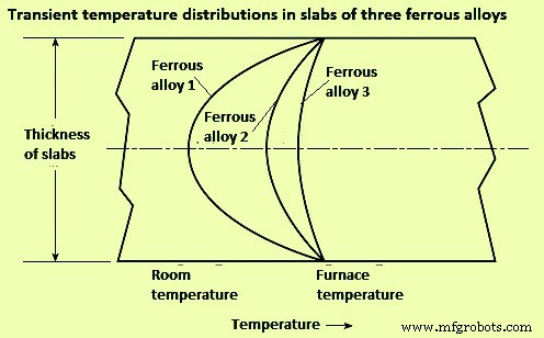
Fig 1 Effect of thermal conductivity on heat flow and internal temperature distribution
Solid materials which are heated in industrial furnaces are not necessarily continuous. Many times, the charge consists of coiled strip material or separate pieces piled to various depths or close side by side. In such cases, heat only can flow from one piece to the adjacent piece through small contact points on their surfaces, or through gas filled spaces, the thermal conductivity of which is very small. A stack of flat plates is an example of very low conductance. Even very small gaps constitute a big thermal resistance than solid metal. A stack cannot be treated as a solid, since thin air spaces are insulators. The differing air gaps in a stack result in bad non-uniformities in temperatures.
Rapid heat flow in each piece of a piled charge is obtained only by circulation of hot gases through the piled material by convection and gas radiation. These gas masses are to be constantly replaced with new hot gas since they have low mass, low specific heat, and thin gas beam thickness, so they cool quickly without delivering much heat to the loads. For uniform heating and precise reproducibility, piling of pieces of materials are to be avoided.
Heat transfer to the surface of the furnace charge – In furnace practice, heat is transferred by three modes namely (i) conduction, (ii) convection, and (iii) radiation. There are some essentials of heat transfer which are helpful to designers and operators of industrial furnaces. Most industrial furnaces, ovens, kilns, incinerators, boilers, and heaters use combustion of fuels as their heat source. Combustion, as used in industrial furnaces, comes from rapid and large chemical reaction kinetics and this result into conversion of chemical energy to sensible heat (thermal) energy. Increasing fuel and oxidizer (usually air) mixing surface area or increasing temperature of the reactants can cause faster combustion reactions, usually resulting in higher heat source temperatures. Fuel oxidation reactions are exothermic, so they can develop into a runaway condition (e.g. thermal energy being released faster than it can be carried away by heat transfer). This positive feedback can cause an explosion.
A flame is a thin region of rapid exothermic chemical reaction. An example is a Bunsen burner flame. In a Bunsen burner, a thoroughly premixed laminar stream of fuel gas and air is ignited by an external heat source, and a cone-shaped reaction zone (flame front) forms. Turbulence increases the thickness and surface area of the reaction zone, resulting in higher burning velocity. Laminar burning velocity for natural gas is around 18 metres per minute (mpm) while the turbulent burning velocity can be two to ten times faster. In a laminar flame, thermal expansion from chemical heat release can combine with increased reactivity caused by higher temperatures, resulting in acceleration to a turbulent flame. Except for long luminous flames, most industrial flames are turbulent.
Conduction heat transfer – Conduction heat transfer is molecule-to-molecule transfer of vibrating energy, usually within solids. Heat transfer solely by conduction to the charged load is rare in industrial furnaces. It occurs when cold metal is laid on a hot hearth. It also occurs, for a short time, when a piece of metal is submerged in a salt bath or a bath of liquid metal.
If two pieces of solid material are in thorough contact (not separated by a layer of scale, air, or other fluid), the contacting surfaces instantly assume an identical temperature somewhere between the temperatures of the contacting bodies. The temperature gradients within the contacting materials are inversely proportional to their conductivities (Fig 2).
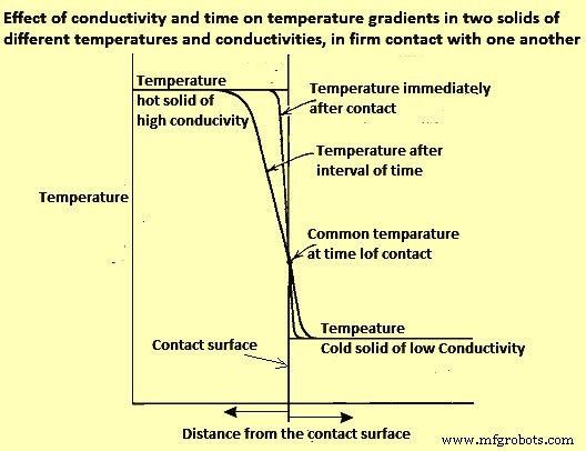
Fig 2 Effect of conductivity and time on temperature gradients in two solids of different temperatures and conductivities, in firm contact with one another
The heat flux (rate of heat flow per unit area) depends not only on the temperatures of the two solids but also on the diffusivities and configurations of the contacting solids. In practice, comparatively little heat is transferred to (or abstracted from) a charge by conduction, except in the flow of heat from a billet to water-cooled skids.
When a piece of cold metal is suddenly immersed in liquid salt, lead, zinc, or any other liquid metal, the liquid freezes on the surface of the cold metal, and heat is transferred by conduction only. After a very short time, the solid jacket, or frozen layer, remelts. From that time on, heat is transferred by conduction and convection.
Convection heat transfer
Convection heat transfer is a combination of conduction and fluid motion, physically carrying heated (or cooled) molecules to another surface. If a stream of gaseous fluid flows parallel to the surface of the solid, the vibrating molecules of the stream transfer some thermal energy to or from the solid surface.
A ‘boundary layer’ of stagnant, viscous, poorly conducting fluid tends to cling to the solid surface and acts as an insulating blanket, reducing heat flow. Heat is transferred through the stagnant layers by conduction. If the main stream fluid velocity is increased, it scrubs the insulating boundary layer thinner, increasing the convection heat transfer rate. The conductance of the boundary layer (film coefficient) is a function of mass velocity (momentum, Re number).
In furnaces which operate below 600 deg C, heat transfer by convection is of major importance since radiation is weak there. Modern high-velocity (high-momentum) burners give high convection heat transfer coefficients. High velocities often provide more uniform temperature distribution around a single piece charge, or among multiple piece charges, since more mass flow carries additional sensible heat at more moderate temperatures. At low furnace temperatures, high rates of total heat transfer can be obtained only by high gas velocities since heat transfer by radiation at around 550 deg C is less than one-tenth of what it is at around 1200 deg C. High-velocity (high momentum) burners are widely used to fill in where radiation cannot reach because of shadow problems.
Radiation heat transfer
Radiation between solids – Heat is radiated by solids even at low temperatures. The net radiant heat actually transferred to a receiver is the difference between radiant heat received from a source and the radiant heat re-emitted from the receiver to the source. The net radiant heat flux between a hot body (heat source) and a cooler body (heat receiver) can be calculated by Stefan-Boltzmann equations.
Emissivity and absorptivity of materials are important properties for radiation between solids. Emissivity is the radiant heat emitted (radiated) by a surface, expressed as a decimal of the highest possible (black body) heat emission in a unit time and from a unit area. Emittance is the apparent emissivity of the same material for a unit area of apparent surface which is actually much greater, due to roughness, grooving, and so on. Absorptivity is the radiant heat absorbed by a surface per unit time and unit area, expressed as a decimal of the most possible (black body) heat absorption.
Engineers use emissivity value of 0. 85 in conventional refractory lined furnaces. However, the temperature, surface condition, and alloy can make considerable difference. As an example, if stainless-steel strip is heated in less than three minutes in a catenary furnace, the emissivity may not change even though the temperature increases from ambient to 1100 deg C. By measuring both strip surface temperature and furnace temperature, it has been possible to revise heating curve calculations, assuming that oxidation has not changed the emissivity or absorptivity during the heating cycle.
Radiation from clear flames and gases – There are two origins of radiation from the products of combustion to solids. The two origins of radiation are (i) from clear flame and from gases, and (ii) from the micron-sized soot particles in luminous flame. Radiation from clear gas does not follow the Stefan-Boltzmann fourth-power law. The only clear gases which emit or absorb radiation appreciably are those having three or more atoms per molecule (triatomic gases) such as CO2, H2O, and SO2 (sulphur di-oxide). An exception is diatomic CO, which gives off less radiation. The other diatomic gases, such as O2, N2 (and their mixture, air), and H2 have only negligible radiating power.
Gaseous radiation does not follow the fourth-power law since gases do not radiate in all wavelengths, as do solids (gray bodies). Each gas radiates only in a few narrow bands. Radiation from clear gases depends on their temperature, on the partial pressure or percent volume of each triatomic gas present, and on the thickness of their gas layer.
The temperature of a radiating gas gets lower in the direction of gas travel. To maintain active gas radiation, the gas is to be continually replaced by new hot gas, which also improves convection. Higher gas feed velocities reduce the temperature drop along the gas path. This factor is very critical in maintaining good temperature uniformity in high temperature industrial furnaces.
The furnaces are often designed on the basis of refractory radiation heating the charge, with usually reasonable results, but some situations cannot be explained by refractory radiation alone. Direct radiation from furnace gases generally delivers 62 % (+/- 2 %) of the heat to the charge, and refractories transfer the remaining 38 % (+/- 2 %). Gas temperatures needed to transfer the heat to refractory and charge are generally much higher than generally assumed.
Radiation from luminous flames – If a fuel-rich portion of an air/fuel mixture is exposed to heat, as from a hotter part of the flame, the unburned fuel molecules polymerize or suffer thermal cracking, resulting in formation of some heavy, solid molecules. These soot particles glow when hot, providing luminosity, which boosts the flame’s total radiating ability.
If fuel and air are not thoroughly mixed promptly after they leave the burner nozzle, they can be heated to a temperature at which the hydrocarbons crack (polymerize). Further heating brings the resulting particles to a glowing temperature. As O2 mixes with them, they burn. As the flame proceeds, formation of new soot particles can equal the rate of combustion of previously formed particles. Farther along the flame length, soot production diminishes, and all remaining soot is incinerated. This series of delayed-mixing combustion processes are to be completed before the combustion gases pass into the flue. If the flame is still luminous at the flue entry, smoke can appear at the stack exit. Smoke is soot that has been cooled (chilled, quenched) below its minimum ignition temperature before being mixed with adequate air.
The added radiating capability of luminous flames causes them to naturally cool themselves faster than clear flames. This is performing their purpose—delivering heat. The cooling phenomenon can negate some of the gain from the higher luminosity (effective emissivity).
Luminous flames often have been chosen because the added length of the delayed mixing luminous flames can produce a more even temperature distribution throughout large combustion chambers. As industrial furnaces are supplied with very high combustion air preheat or more oxy-fuel firing, luminous flames can enable increases in heat release rates.
Fuels with high C/H2 ratios (most oils and solid fuels) are more likely to burn with luminous flames. Fuels with low C/H2 ratios (mostly gaseous fuels) can be made to burn with luminous flames namely (i) by delayed mixing, injecting equally low-velocity air and gas streams side-by-side, and (ii) by using high pressure to ‘shoot’ a high-velocity core of fuel through slower moving air so that the bulk of the air cannot ‘catch up’ with the fuel until after the fuel has been heated (and polymerized) by the thin ‘sleeve’ of flame annular interface between the two streams.
Flames from solid fuels can contain ash particles, which can glow, adding to the flame’s luminosity. With liquid and gaseous fuels, flame luminosity usually comes from glowing C and soot particles. The effective flame emissivity, as measured is usually between that of the POC gases and a maximum value of 0.95, depending on the total surface area of solid particles. Normally, heat transfer from a luminous flame is greater than that from a clear flame having the same temperature. The difference in the rate of heat transfer is quite noticeable in furnaces for reheating steel and metals. The difference becomes more pronounced at high temperature, where the radiating power of each triatomic gas molecule increases, but the gain is partially canceled by the decreasing density of radiating molecules per unit volume.
In another phenomenon, the bands of gaseous radiation hold their wavelengths regardless of temperature. At higher temperatures, however, the area of high intensity of solid radiation (glowing soot and C particles) moves toward shorter wavelengths (away from the gas bands). In higher temperature realms, radiation from clear gases does not increase as rapidly as radiation from luminous flames.
Flame radiation is a function of many variables such as C/H2 ratio of the fuel, air/fuel ratio, air and fuel temperatures, mixing and atomization of the fuel, and thickness of the flame. Some of these can change with distance from the burner. Fuels with higher C/H2 ratio, such as oils, tend to make more soot, so they usually create luminous flames, although blue flames are possible with light oils. Many gases have a low C/H2 ratio, and tend to burn clear or blue. It is difficult to burn tar without luminosity. It is equally difficult to produce a visible flame with blast furnace (BF) gas or with H2.
When comparing luminous and nonluminous flames, it is important to remember (i) soot radiation (luminous) usually ends where visible flame ends because soot is most often incinerated at the outer surface or skin of the flame, where it meets secondary or tertiary air, and (ii) gas radiation (nonluminous) occurs from both inside and outside the visible flame envelope, greatly increasing the uniformity and extent of its coverage, although gas radiation within the flame is somewhat shadowed by any surrounding soot particles or triatomic gases, and gas radiation outside the flame can be from cooler gases.
The effect of excess fuel on flame radiation is considerably greater than the effect of less excess air. The merits and demerits of clear flames versus long luminous flames have been debated for years. Modified burners and control schemes are helping to utilize the best of both. A problem common to several burner types is change of the flame characteristic as the burner input is turned down. Problems with some clear flame burners are (i) movement of the hump in the temperature profile closer to the burner wall as the firing rate is reduced, and (ii) at lower input rates, temperature falls off more steeply at greater distances from the burner wall (e.g., the temperature profile of a burner firing at 50 % of its rated capacity or below is at its peak temperature (maximum heat release at or near the burner wall, falling off further from the burner wall). At lower firing rates, the temperature drop off gets worse. At higher firing rates, the burner wall temperature decreases as the peak temperature moves away from it. In some steel reheating furnaces at maximum firing rate, the temperature difference between the burner wall and the peak can be 150 deg C.
The problem of a temperature peak at the far wall during high fire is aggravated by spur of furnace gases into the base of the flame, delaying mixing of fuel with O2. If the burner firing rate is increased, the spur of the products of complete combustion increases exponentially. Resulting problems are many. When side-firing a furnace at low firing rate, the peak temperature is at the burner wall, but at maximum firing rate, the peak temperature can be at the furnace centre or the opposite wall. Thus, the location of a single temperature control sensor is never correct. If the temperature sensor is in the burner wall, low firing rates have peak temperature hugging the furnace wall and driving the burner to low fire rate resulting into the rest of the furnace width receiving inadequate input. At high firing rates, a sensor in the burner wall is cool while the temperature away from the burner wall is very high, perhaps forming liquid scale on the surfaces of the charge pieces at the centre and/or far wall. To remedy this issue, inexperienced operators can lower the set point, reducing the furnace heating capacity.
Another example of the effect of the problem occurs with the bottom zone of a steel reheating furnace when fired longitudinally counter flow to the load movement, and with the control sensor installed 3 metre (m) to 6 m from the (end-fired) burner wall. At low-firing rates, with the zone temperature set at 1300 deg C, the burner wall can rise to higher than 1370 deg C. At that temperature, scale melts and drips to the floor of the bottom zone where it can later solidify as one big piece. At high firing rates, the peak temperature can move beyond the bottom zone T-sensor, possibly melting scale some distance toward the charge end of the furnace. Again, to avoid the problem, operators can lower temperature control settings, reducing the furnace capacity.
Control of the aforementioned problems requires an additional temperature sensor in each zone and a means for changing the mixing rate characteristic of the burner in response to the temperature measurements. Burners with adjustable spin (swirl) can be set to prevent much of the problem, especially if combined with a low-fire, forward-flow gas or air jet through the center of the burner. Such a jet is typically sized for 5 % of maximum gas or air flow.
Long, luminous flames, either laminar type or turbulent type, tend to have much less temperature hump and do not change length as rapidly when input is reduced. They can be great ‘levelers’, providing better temperature uniformity.
This information on in-flame soot radiation and triatomic gas radiation has been known for some time, but recent developments may be changing the picture. Use of oxy-fuel (100 % O2), both of which elevate flame turndown. The major gain from oxy-fuel firing is from more intense radiation heat transfer because of the higher concentration of triatomic gases, due to the elimination of N2 from the POC. This also decreases the mass of gas carrying heat out the flue (reducing stack loss). In another development, some lean premix gas flames (designed for low NOx emissions) make a ubiquitous flame field (seemingly transparent) through much of the chamber.
製造プロセス