


炭素鋼および合金鋼の鍛造
炭素鋼および合金鋼の鍛造
炭素(C)および合金鋼の鍛造は、金属加工プロセスを構成します。これは、鍛造材料の鋳造構造を改良し、収縮ボイドを修復し、素材。完成品の形状や使用する鍛造工程にもよりますが、その後の機械加工の量も減ります。
鋳造インゴットは、インゴットから直接鍛造するか、インゴットから熱間加工されたブルームまたはビレットから鍛造するための伝統的な鍛造の出発点でした。連続鋳造鋼の普及により、現在では通常、連続鋳造品が初期ストックとして使用されています。鋳造インゴット、圧延および鋳造ブルームおよびビレットに加えて、鍛造用の他の出発材料は、プレート、バーおよびロッド、および鋼鋳物です。
鉄鋼の鍛造は鉄器時代の初めから始まりました。当時、ハンマーによる熱間加工は、錬鉄を製造するプロセスの一部であり、錬鉄と鋼の両方で製品を製造するプロセスの一部でした。高品質の鉄鉱石、木炭、およびフラックスを使用する原油製錬炉は少量の鉄を生成し、有用なストックを生成するために手で鍛造溶接する必要がありました。当初、これが当時の鍛造の主な目的でした。産業革命の始まりは、鋼の鍛造から始まったと一般に認められています。この長い歴史にもかかわらず(またはおそらくそのせいで)、鋼の鍛造は直感的で経験的なプロセスです。
鍛造品は通常、オープンダイ鍛造とクローズドダイ鍛造の一般的な分類から始めて、いくつかの方法で分類されます。それらはまた、完成に近い要因、または完成部品の寸法および詳細要件を満たすために機械加工によって鍛造品から除去されるストック(カバー)の量の観点から分類されます。最後に、鍛造品は、ハンマーアプセット鍛造品、リングロール鍛造品、マルチラムプレス鍛造品など、製造に必要な鍛造設備の観点からさらに分類されます。さまざまな分類の中で、仕上げに近い要因に基づく分類は、強度や応力腐食に対する耐性など、鍛造品の固有の特性に最も密接に関連しています。一般に、完成品の要件を満たすために必要な機械加工が最も少ないタイプの鍛造品が、最高の特性を備えています。
ASTM仕様A788によると、鋼の鍛造品は、材料を固め、目的の形状を生成する、実質的に圧縮されたプラスチック加工操作の結果です。塑性加工は、ハンマー、プレス鍛造機、またはリング圧延機で行うことができ、本質的に鍛造された構造を生成するために材料を変形させる必要があります。熱間圧延操作を使用して、再鍛造用のブルームまたはビレットを製造することができます。鍛造品は、鍛造温度に基づいて次の3つのクラスに分類できます。
- 熱間加工鍛造品–材料の再結晶温度を超える温度で加工して製造された鍛造品。
- 熱間冷間加工鍛造品–鍛造品は、再結晶温度よりわずかに低い高温で加工され、機械的強度を高めました。熱間冷間加工鍛造品は、鍛造または圧延によって以前に熱間加工された材料から製造することができる。熱間冷間鍛造は、材料を最初に熱間加工し、次に仕上げ温度の制御によって冷間加工する1つの連続操作で行うことができる。熱間圧延、または熱間および冷間仕上げのバー(半完成または完成)の製造には違いがあるため、ビレットまたはブルームは鍛造品とは見なされません。
- 冷間加工鍛造品–材料の再結晶が発生する温度範囲よりも十分に低い温度でプラスチックが加工されて製造された鍛造品。冷間加工された鍛造品は、鍛造または圧延によって以前に熱間加工された材料から作成する必要があります。
鋼の鍛造製品の形態には、プレート、形状、バー、シート、ストリップ、チューブ、パイプ、押し出し、および鍛造品が含まれます。通常、押し出しは鍛造品に含まれますが、鍛造品の定義には、圧延プレートとバーは含まれません。これは、鍛造品は、必要なコンポーネントの完成形状にほぼ一致するだけでなく、熱間圧延プレートに関連する場合がある厚さの弱さ、または熱間圧延バーに関連する場合がある中央の不健全性によって層流介在物の特性を示すことが期待されないためです。
炭素鋼と合金鋼は通常、群を抜いて最も鍛造された材料であり、熱間鍛造、温間鍛造、または冷間鍛造プロセスと標準装備を使用して、さまざまな形状に容易に鍛造されます。炭素鋼および合金鋼の鍛造温度の選択は、炭素含有量、合金組成、最適な塑性のための温度範囲、およびワークピースを鍛造するために必要な還元量に基づいています。これらの要因の中で、炭素含有量が鍛造の上限温度に最も影響を与えます。
利用可能な組成物の数が多いにもかかわらず、このカテゴリーのすべての材料は、本質的に同様の鍛造特性を示しています。例外は、硫化物などのフリーマシニング添加剤を含む鋼です。これらの材料は、非フリーマシニンググレードよりも鍛造が難しいためです。通常、炭素鋼および合金鋼の熱間鍛造性は、変形速度が増加するにつれて向上します。作業性の向上は、主に高い変形率で発生する変形熱の増加によるものです。
他の、時にはより経済的な、有用な形状を生成する方法よりも鍛造を選択することの正当性は、いくつかの考慮事項に基づいています。鍛造材料の機械的特性は、作業中の主要な金属の流れの方向に最大化されます。複雑な形状の場合、鍛造のみが、金属の流れを主要な適用される使用荷重と平行に向け、鍛造材料の元の構造の改良を制限内で制御する機会を与えます。微細構造の微細化は、温度、方向、および鍛造材料から鍛造形状への減少の大きさの関数です。材料の構造的完全性を最大化することにより、設計構成の改良が可能になり、それにより重量の削減が可能になります。複雑な鍛造構成で特性を最適化するための金属の流れの適切な制御には、通常、ダイ鍛造の前に1つ以上のアプセット操作が必要であり、ダイパーティングラインでのフラッシュ形成を回避するために中空鍛造または逆押し出しが必要になる場合があります。
鋼鍛造品が果たすことを目的とした機能のために、鍛造品の設計には多くの場合、大きな熱処理セクションサイズが含まれ、不規則な形状になる可能性があります。そのため、3つの主軸すべてに大きな応力を加えることができます。 、(ii)横方向、および(iii)短い横方向。出発材料のサイズと鍛造ステップを注意深く選択することにより、鍛造は3方向すべてで良好な特性を示すことができます。他の例では、例えば、アプセットディスク鍛造では、全周の半径方向に好ましい機械的特性を達成することができます。これは、圧延板から単純に切り取られたディスクで可能です。
熱間鍛造の動作
炭素鋼および合金鋼の複雑な形状への熱間鍛造は、フリーマシニンググレードを除いて、鍛造性の側面によって制限されることはめったにありません。断面の厚さ、形状の複雑さ、および鍛造サイズは、主に、加熱されたワークピースがコールドダイと接触したときに発生する冷却によって制限されます。このため、鋼の複雑な形状を鍛造するには、ハンマーなどのダイ接触時間が比較的短い装置が好まれることがよくあります。
鍛造性 –鍛造性とは、圧縮荷重下で破壊することなく流動する鋼の相対的な能力です。再硫化および再リン酸化グレードを除いて、ほとんどの炭素鋼および低合金鋼は通常、良好な鍛造性を備えていると考えられています。鋼のさまざまなグレード間の鍛造挙動の違いは十分に小さいため、鍛造挙動による鋼の選択にほとんど影響を与えません。ただし、鍛造による生産を検討する主な理由の1つはその後の機械加工作業の回避であるため、鍛造に再硫化または再リン酸化鋼を選択することは、通常、鍛造を広範囲に機械加工する場合にのみ正当化されます。この状況はまれです。
鋼の鍛造性を測定する一般的な方法の1つは、ホットツイストテストです。名前が示すように、このテストでは、加熱されたバーのサンプルをねじって、テスト材料の可能な熱間加工温度範囲をカバーするように選択されたさまざまな温度で破壊します。破壊するねじれの数、およびねじれを一定の速度で維持するために必要なトルクが報告されます。撚り数が最大となる温度は、そのような最大値が存在する場合、試験材料の最適な熱間加工温度であると想定されます。ホットツイスト試験によって決定されたいくつかの炭素鋼の鍛造性を図1に示します。鋼の鍛造性を評価するために、以下に示す他のさまざまな試験が使用されます。
- くさび鍛造試験–この試験では、くさび形の試験片を平らなダイの間に鍛造し、亀裂の原因となる垂直方向の変形を確立します。
- サイドプレステスト–このテストは、円筒の軸がダイに平行な状態で、平らな平行なダイ間で円筒形の棒のサンプルを圧縮することで構成されます。シリンダーの端には拘束がなく、鍛造性は亀裂が発生する前に得られた変形量によって測定されます。
- アプセットテスト–このテストでは、シリンダーを平らなダイの間で圧縮し、シリンダーの赤道での破壊時の表面ひずみを測定します。
- ノッチ付きバーアプセットテスト–このテストは、アキシャルノッチをテストサンプルに機械加工して高い局所応力レベルを導入することを除いて、アプセットテストと同様です。これらのより高い応力は、標準のアプセットテストで生成された応力よりも実際の鍛造操作中に発生した応力をよりよく示している可能性があります。
- 熱間引張試験–この試験では、特殊な試験装置を頻繁に使用して、ひずみ速度と温度の両方を広範囲にわたって変化させます。
鍛造性に対するひずみ速度の影響 –鋼の鍛造性は、一般にひずみ速度の増加とともに増加します。この効果は、ホットツイスト試験で低炭素鋼に示されています(図1)。この場合、ねじれ率の増加に伴い、破損までのねじれの数が増加します。より高いひずみ速度での鍛造性のこの改善は、より高いひずみ速度で生成される変形熱の増加によると考えられている。ただし、変形熱によって過度の温度が上昇すると、初期溶融が発生し、鍛造性と機械的特性が低下する可能性があります。
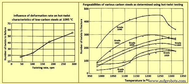
図1さまざまな炭素鋼の変形速度と鍛造性の影響
流動応力と鍛造圧力 –流動応力と鍛造圧力は、熱間ねじり試験または熱間圧縮または引張試験で生成されたトルク曲線から取得できます。これらの曲線のデータは、このグループの合金の相対的な鍛造圧力要件は、通常の熱間鍛造温度では大きく変化しないことを示しています。より高度に合金化された材料にはかなり大きな圧力が必要であり、この合金材料はまた、減少の増加に伴って鍛造圧力のより大きな増加を示します。
鍛造圧力に対するひずみ速度の影響 –特定の鋼に必要な鍛造圧力は、ひずみ速度の増加とともに増加します。低炭素鋼の研究は、ひずみ速度の影響がより高い鍛造温度でより顕著であることを示しています。この効果を図2に示します。これは、さまざまな温度とひずみ速度で鍛造された低炭素鋼の応力-ひずみ曲線を示しています。同様の効果が合金鋼でも観察されています。
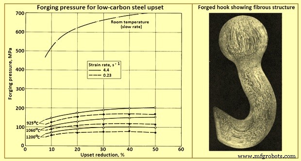
図2さまざまな温度と2つのひずみ速度での低炭素鋼のアプセットに対する鍛造圧力
鍛造用鋼の選択
鍛造用の炭素鋼および合金鋼のインゴット、ブルーム、ビレット、およびスラブは、おおよその断面寸法に熱間圧延または鋳造されるため、真直度、反り、ねじれ、および平坦度の許容誤差は適用されません。鍛造用の半製品は、指定されたピースの重量または指定された長さで製造されます。
表面調整 –鍛造用の半製品は、表面の欠陥を除去または最小限に抑えるために、スカーフィング、チッピング、または研削によって調整できます。ただし、表面のコンディショニングに関係なく、製品には表面の欠陥が含まれている可能性があることに注意してください。
重量公差 –ビレット、ブルーム、およびスラブの許容誤差は、個々のピースまたは18トン未満のロットの場合は+/- 5%であることがよくあります。それ以上の重量のロットは、多くの場合、+ /-2.5%の重量公差の対象となります。
カッティング –鍛造用の半製品は、通常、熱間せん断によって長さに切断されます。鋼の組成に応じて、ホットソーイングまたはフレームカットも使用できます。
品質 –この用語が鍛造用の半製品に適用される品質は、内部の健全性の程度、化学組成の相対的な均一性、表面の欠陥からの相対的な自由度など、さまざまな要因に依存します。
鍛造品質の半製品鋼は、その後の熱処理または機械加工操作を伴う可能性のある熱間鍛造用途で使用されます。このようなアプリケーションでは、化学組成と鉄鋼生産を比較的厳密に制御する必要があります。
鍛造部品用の鋼の選択は設計プロセスの不可欠な部分であり、許容できる性能はこの選択に依存します。完成部品の最終用途を注意深く理解することは、必要な機械的特性、表面仕上げ要件、非金属介在物に対する耐性、および付随する検査方法と基準を定義するのに役立ちます。
鍛造品質の鋼は、幅広い化学組成で製造されています。溶解と圧延の各慣行では、品質のテストと評価のレベルが行われます。必要に応じて、非金属介在物の発生レベルなど、鋼に1つ以上の特別な品質制限を指定できます。場合によっては、信頼性の高いアプリケーションでは、鋼を真空アーク再溶解またはエレクトロスラグ再溶解プロセスにかける必要があります。
マイクロ合金鋼の使用は、自動車のクランクシャフトなどの用途で近年進化しています。これらの鋼は通常、バナジウムまたはニオブを少量(0.05%から0.1%)添加しており、熱処理されていない(鍛造された)状態で許容可能な特性を達成できます。その結果、これらの合金は、熱処理サイクルが不要なため、鍛造プロセスの利点を維持しながら、鋳造品と経済的に競争力があります。
設計要件 –鍛造部品用の鋼の選択には、通常、強度と靭性、応力耐食性と重量、製造コストと有用な耐荷重能力、製造コストと保守コスト、および鋼原料対鍛造の総製造コスト。材料の選択には、溶解方法、成形方法、機械加工操作、熱処理手順、使用時間の経過に伴う特性の劣化、および鍛造される鋼の従来の機械的および化学的特性の考慮も含まれます。
効率的な鍛造設計は、加えられる荷重、生産性、および望ましい寿命と一致する最小量の材料から最大の性能を達成します。鋼をその設計コンポーネントに適合させるために、鋼は最初に強度と靭性について評価され、次に温度と環境に対する安定性について認定されます。次に、最適な鋼の生産性を分析し、最終的に経済性を分析します。
故障解析は、鋼の特性を要件に一致させるための有用なデータソースです。コンポーネントの故障は、設計応力範囲内の動作中に発生する可能性があります。早期故障の原因の1つは、鍛造品の好ましい結晶粒の流れによる重要な設計応力の適切な方向付けの欠如です。時間とサービスによる特性の劣化が原因で、予期しない障害が発生することもあります。たとえば、持続的な引張応力に起因する応力腐食割れは、通常の周囲雰囲気でも発生する可能性があります。これらの条件下では、露出したエンドグレインと一致する鍛造品の場所で故障が発生する可能性が最も高くなります。故障解析では、過度の結晶粒成長、非金属不純物の含有、不適切な鍛造作業による結晶粒の流れの折り畳み、鍛造冶金構造の欠如、過度の機械加工による応力集中部の不注意な生成など、早期故障の他の原因を明らかにすることができます。鋭いフィレットまたはアセンブリへの適合性の悪さ。
鍛造が特性に及ぼす影響
炭素鋼または合金鋼の棒鋼またはビレットからの複雑な構成の成形では、最初に鋼を適切な開始形状(予備成形)に「配置」してから、最終部品構成に流し込む必要があります。この金属の再配列は、鋼の硬度と強度にほとんど影響を与えませんが、特定の機械的特性(延性、衝撃強度、疲労強度など)が強化されます。この特性の改善(図2)は、鍛造が(i)偏析を破壊し、多孔性を修復し、均質化を促進し、(ii)粒子の流れに平行な機械的特性を強化する繊維状の粒子構造を生成し、(iii)次のように減少するために発生します。 -鋳造粒子サイズ。
鍛造品の減少の関数としての熱処理鋼の延性と衝撃強度の典型的な改善を図3に示します。これらのデータは、それぞれの場合で最大の伸びの方向で最大の改善が起こることを示しています。靭性と延性は、ある程度の減少後に最大に達し、その後、それ以上の減少はほとんど価値がありません。
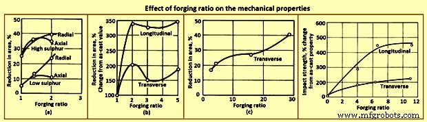
図3機械的特性に対する鍛造比の影響
表1は、焼きなまし、正規化、焼入れ、焼き戻しの条件での低炭素鋼および中炭素鋼の鍛造品の典型的な縦方向の機械的特性を示しています。予想されるように、強度は炭素含有量の増加とともに増加しますが、延性は減少します。ほとんどの場合、クローズドダイ鍛造は、かなりの事前作業を受けた鍛造ビレットから作られていることを認識しておく必要があります。ただし、オープンダイ鍛造品は、鍛造ビレットまたは鋳造品のいずれかから製造できます。
| タブ14つの炭素含有量での炭素鋼鍛造品の縦方向の特性 | |||||||
| Sl。No. | 降伏強度、0.2%オフセット | ||||||
| % | MPa | MPa | % | % | MPa | HB | |
| アニーリング | |||||||
| 1 | 0.24 | 438 | 201 | 39 | 59 | 185 | 122 |
| 2 | 0.30 | 483 | 245 | 31.5 | 58 | 193 | 134 |
| 3 | 0.35 | 555 | 279 | 24.5 | 39 | 224 | 157 |
| 4 | 0.40 | 634 | 348 | 24 | 42 | 248 | 180 |
| 正規化 | |||||||
| 1 | 0.24 | 483 | 247 | 34 | 56.5 | 193 | 134 |
| 2 | 0.30 | 521 | 276 | 28 | 44 | 209 | 148 |
| 3 | 0.35 | 579 | 303 | 23 | 36 | 232 | 164 |
| 4 | 0.40 | 690 | 355 | 22 | 36 | 255 | 196 |
| オイルを595℃で急冷および焼き戻し | |||||||
| 1 | 0.24 | 500 | 305 | 35.5 | 62 | 193 | 144 |
| 2 | 0.30 | 552 | 301 | 27 | 52 | 224 | 157 |
| 3 | 0.35 | 669 | 414 | 26.5 | 49 | 247 | 190 |
| 4 | 0.40 | 724 | 386 | 19 | 31 | 277 | 206 |
| *10,000,000の耐久限度での回転ビームテスト | |||||||
クローズドダイ鍛造では、金属がさまざまな方向に流れます。一例として、エアフレーム部品などのリブおよびウェブ形状の鍛造では、ほとんどすべての金属の流れが横方向である。このような横方向の流れは、縦方向の延性をほとんどまたはまったく低下させることなく、その方向の延性を改善します。鍛造品の減少が十分に大きく、金属の流れが主に横方向である場合、横方向の延性はおそらく縦方向の延性と同等かそれを超える可能性があります。鍛造ビレットの動揺にも同様の影響が見られます。ただし、この場合、材料の元の縦軸はアプセットによって短くなり、金属の横方向の変位は半径方向になります。動揺の減少が約50%を超えると、通常、半径方向の延性は軸方向の延性を超えます(図4)。
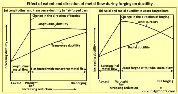
図4鍛造鋼の軸方向および半径方向の延性に対するアプセット低減の典型的な影響
鍛造構造と延性 –材料管理の別の側面により、最終鍛造品が十分な塑性変形を受けて、設計の基礎となった機械的特性の開発に必要な鍛造構造を実現できるようになります。鋳造製品を鍛造ビレットに分解する際にある程度の塑性変形が達成されますが、クローズドダイ鍛造プロセス中にははるかに多くの変形が生じます。高強度鍛造品の材料管理では、鍛造品の機械的特性だけでなく、鍛造ビレットの機械的特性も決定する必要があります。
延性または靭性の尺度は、横方向の張力試験サンプルで得られた面積の減少を測定することによって決定されます。同じ強度レベルに熱処理された鍛造品から採取された横方向および縦方向のサンプルで対応するテストが行われる場合、ビレットストックと鍛造品の機械的特性を比較し、それぞれが寄与する最終的な鍛造冶金構造の割合を推定することができます。
延性と鍛造削減量 –材料管理の主な目的は、完成した鍛造品で最適な機械的特性が確実に達成されるようにすることです。鍛造で達成された減少量は、鋳造インゴット、鍛造(圧延)バーまたはビレット、および鍛造の延性を比較する図4に示すように、延性に著しい影響を及ぼします。図4(a)の曲線は、鍛造バーまたはビレットがダイでフラット鍛造された場合、鍛造の減少の増加は縦方向の延性に影響を与えませんが、横方向の延性は徐々に増加することを示しています。同様のバーまたはビレットがダイで鍛造された場合、鍛造の減少が増えると、軸方向の延性が徐々に低下し、半径方向の延性が徐々に増加します。
鋳造インゴットの延性は、化学組成、溶解方法、およびインゴットのサイズによって異なります。同じ合金組成の鋼塊の延性も、それらが空気溶融鋼から注がれるか真空アーク再溶融鋼から注がれるかによって異なります。特定の合金の大きなインゴットから始める場合、鍛造の削減量を変えて、インゴットの一部をさまざまなビレットまたはバーのサイズに圧延することが実際的である場合があります。最小削減量は標準ではありませんが、2:1(インゴットセクションの面積とビレットセクションの面積の比率)未満になることはめったにありません。鋼塊のビレットへの還元は通常2:1よりはるかに大きい。対照的に、一部の耐熱合金鍛造品は、鋳造インゴットから直接鍛造されています。
多くの場合、インゴットの全重量を必要とするほど大きい鍛造品用のビレットを準備することは不可能です。鍛造冶金構造によって表される鍛造品の削減量は、完成した鍛造品から採取したマクロエッチングおよび引張試験サンプルの観察と試験によって最もよく制御されます。これらのサンプルは、重要な領域、そして一般的には鍛造品全体の探査を可能にします。それらは、必要に応じて、縦方向、長横方向、および短横方向の粒子方向から選択されます。エッチング試験により、粒子の流れを視覚的に観察できます。機械的試験は、強度と靭性を粒子の流れと相関させます。
穀物の流れ –マクロエッチングにより、粒子の方向と輪郭を直接観察でき、折り目、ラップ、およびリエントラントフローを検出することもできます。適切なサンプルをマクロエッチングすることにより、粒子の流れを縦方向、長横方向、および短横方向に調べることができます。マクロエッチングにより、完全なセクション、エンドツーエンドおよびサイドツーサイドの評価、およびマクロ粒子サイズの均一性のレビューも可能になります。図2に代表的な鍛造部品の粒流を示します。
粒度と微量成分 –顕微鏡を使用した金属組織検査は、マクロエッチングによって明らかになった疑わしい領域の検査、粒子サイズの測定、および微量成分の性質と量の決定に最適です。
疲労強度 –疲労試験は、(i)材料の開発または認定のための少量サンプルの実験室試験、(ii)設計開発のための完全なコンポーネントまたはサブアセンブリの実験室試験、および(iii)現場でのコンポーネントまたはアセンブリの監視により、サービスにおける継続的な信頼性を確保します。
材料の認定または開発のための少量サンプルの実験室疲労試験は、標準的な方法で行われます。テストサンプルは、必要に応じて、ミル製品またはクローズドダイ鍛造品のいずれかから採取されます。標準サンプルは、鍛造品内の多くの場所からの選択を可能にし、粒子の流れのさまざまな方向と相関させるのに十分小さいです。テストは通常、室温で空気中で行われますが、高温または低温で、特別な雰囲気でテストすることも可能です。
コンポーネントまたはアセンブリの分析に小規模な実験室疲労試験を適用すると、追加の変数が発生します。 1つは表面状態の影響です。図5(a)の曲線は、表面が研磨されているか、機械加工されているか、熱間圧延されているか、または鍛造されているかによって、鋼サンプルの疲労強度が著しく変化することを示しています。テストされた鋼は、269HBから285HBに熱処理された鍛造低合金鋼であり、引張強度876MPaおよび降伏強度696MPaに相当します。サンプルの準備には、熱処理後にサンプルを機械加工および研磨し、熱処理の前に圧延または鍛造する必要がありました。 106サイクルの疲労寿命の場合、疲労限度は、粉砕サンプルで395 MPa、機械加工サンプルで315 MPa、圧延サンプルで205 MPa、鍛造サンプルでわずか150MPaです。
図5(b)の曲線は、引張強度が345MPaから2,070MPaの範囲の鋼に適用され、いくつかのテストからの近似値です。 965 MPaの引張強度レベルでの鍛造または脱炭サンプルのサンプル準備には、棒鋼から粗加工され、ガス焚きマフ炉で約900℃に20分から30分間加熱され、元の鋼から非常に軽く削られた鋼が含まれます。直径7.47mmから最終直径7.16mmまで、空冷。熱処理は、約830℃の塩浴で45分間のオーステナイト化、油焼入れ、約620℃の空気中で1時間の焼戻し、および水焼入れから成っていた。鍛造と熱処理により、約0.064mmの深さまで脱炭された表面が生成されました。これらのサンプルは、106サイクルで、約310 MPaの疲労強度を示しています。これに対して、鍛造されていないが機械加工または研磨され、脱炭されていないサンプルの疲労強度は470MPaです。脱炭は、熱処理によって得られる強度レベルを低下させます。表面状態の実験室での管理は、鍛造部品の大量生産で再現することは困難です。したがって、フルサイズのコンポーネントの疲労強度は、表面状態の変化により、小さなサンプルの疲労強度よりも広い範囲で変化します。
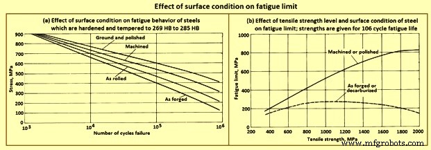
図5疲労限度に対する表面状態の影響
破壊靭性 –鋼の降伏強度を大幅に下回る応力レベルでの亀裂伝播の結果としての鍛造品およびその他のコンポーネントの脆性破壊は、破壊特性および破壊靭性を評価する方法の広範な研究につながりました。これらの研究の結果は、特に材料管理の基準に基づく破壊靭性を評価するためのテストの開発に関して、材料管理にとって非常に重要です。
In the area of laboratory tests and analytical techniques, major emphasis has been placed on the development of dependable methods for evaluating the strength of steels which contain cracks or crack like defects. Specifically, interest has centered on methods for determining plane-strain fracture toughness. Forged components are evaluated by testing small samples removed from selected locations on the forging which are representative of the various grain directions.
One test procedure comprises the bend testing of the notched and fatigue-cracked samples in a neutral environment. The objective of this test is to get a lower limiting value of fracture toughness which can be used to estimate the relationship between stress and defect size in a metal under service conditions in which high constraint is expected. In the test procedure referred to, a test sample with a chevron notch is suitably pre-cracked in fatigue. It is then tested in a bend test fixture provided with support rolls which rotate and move apart slightly to permit rolling contact and virtually eliminate the friction effect. The sample is subjected to three-point bending, and the imposed load versus displacement change across the notch is recorded on an autographic recorder. Fracture toughness is rated by a calculated parameter, the critical stress intensity.
End-grain exposure – Lowered resistance to stress-corrosion cracking in the long-transverse and short-transverse directions is related to the end-grain exposure. A long, narrow test sample sectioned so that the grain is parallel to the longitudinal axis of the sample has no exposed end grain, except at the extreme ends, which are not subjected to the loading. In contrast, a corresponding sample cut in the transverse direction has end-grain exposure at all points along its length. End grain is especially pronounced in the short-transverse direction on die forgings designed with a flash line. Consequently, forged components designed to reduce or eliminate end grain have better resistance to stress-corrosion cracking.
Residual stress – The sustained tensile stress at the surface of a forging which contributes to stress-corrosion cracking is the total of applied and residual stresses. When the residual stress constitutes a significant percentage of the total stress, it is to be reduced or eliminated. Common sources of residual tensile stresses include quenching, machining, and poor fit in assembly. Each can be suitably modified to reduce or eliminate tensile stresses, especially those present in an exposed surface. As an example, drastic quenching places the surface of a heat-treatable alloy in a state of compression and the core in a state of tension. Furthermore, the compressed surface can be entirely removed during rough machining, exposing the tension-stressed core material. This hazard can be avoided by quenching after, rather than before, rough machining. In some applications, a surface in tension is placed in compression by shot peening.
Hydrogen-stress cracking occurs without corrosion. Hence, its initiation is not confined to exterior surfaces in contact with a corrosive medium. It can start at any suitable nucleus, such as an inclusion or void, as well as at a surface notch or other irregularity. Hydrogen-stress cracking at the interior is described as hydrogen embrittlement or hydrogen flaking. Hydrogen-stress cracking has been observed, studied, and brought under control in most high-strength steels. The modern practice of vacuum melting can reduce residual hydrogen to negligible amounts. A hydrogen content of 3 ppm to 6 ppm in air-melted steel can be readily lowered to 0.6 ppm to 1 ppm by vacuum arc remelting. Provided that the initial hydrogen content of the steel is acceptably low, material control procedures are to ensure that hydrogen pickup is avoided in all subsequent processing, including forging, heat treating, hot salt bath descaling, pickling, and plating. During forging, steels develop a surface scale and a decarburized surface layer, both of which are subsequently removed by grit blasting and machining. Unless the steel is acid pickled, there is no possibility of hydrogen pickup.
Many of the critical parts made from steel forgings are protected by a coating of cadmium. Steel parts heat treated to strength levels higher than 1,655 MPa are especially sensitive to hydrogen pickup, in case they are coated with cadmium, the coating is deposited in vacuum. Parts heat treated to strength levels lower than 1,655 MPa can be cadmium plated electrolytically, provided that a titanium-containing plating bath is used and the parts are subsequently baked at around 190 deg C for 12 hours.
Mechanical properties – A major advantage of shaping metal parts by rolling, forging, or extrusion stems from the opportunities such processes offer the designer with respect to the control of grain flow. The strength of these and similar wrought products is almost always greatest in the longitudinal direction (or equivalent) of grain flow, and the maximum load-carrying ability in the finished part is achieved by providing a grain-flow pattern parallel to the direction of the major applied service loads when, in addition, sound, dense, good-quality metal of sufficiently fine grain size has been produced throughout.
Grain flow and anisotropy – Steel which is rolled, forged, or extruded develops and retains a fiber like grain structure aligned in the principal direction of working. This characteristic becomes visible on external and sectional surfaces of wrought products when the surfaces are suitably prepared and etched. The fibers are the result of elongation of the micro-structural constituents of the steel in the direction of working. Hence, the phrase ‘direction of grain flow’ is normally used to describe the dominant direction of these fibers within wrought metal products.
In wrought steel, the direction of grain flow is also evidenced by measurements of mechanical properties. Strength and ductility are almost always greater in the direction parallel to that of working. The characteristic of showing different strength and ductility values with respect to the direction of working is referred to as mechanical anisotropy and is exploited in the design of wrought products. Although the best properties in wrought steels are most frequently the longitudinal (or equivalent), properties in other directions can yet be superior to those in products not wrought, that is, in cast ingots or in forging stock taken from a lightly worked ingot.
Rectangular sections show anisotropy among all the three principal directions i.e. longitudinal, long transverse, and short transverse. A design which employs a rectangular section involves the properties in all these directions, not just the longitudinal. Hence, the longitudinal, long-transverse, and short-transverse service loads of rectangular sections are analyzed separately.
Anisotropy in high strength steel – Although all wrought steels are mechanically anisotropic, the effects of anisotropy on mechanical properties vary among different metals and alloys. For example, a vacuum-melted steel of a given composition is generally less mechanically anisotropic than a conventionally killed, air-melted steel of the same composition. Response to etching to reveal the grain flow characteristic of anisotropy also varies. Steels with poor corrosion resistance are readily etched, while those with good corrosion resistance need more corrosive etchants and extended etching times to reveal grain flow. In general, fatigue properties are markedly affected by the relation of flow-line direction to direction of stresses from applied loads. When flow lines are perpendicular to load stresses, a stress-raising effect is produced.
Forging lubricants
For many years, oil-graphite mixtures have normally being used as lubricants for forging carbon and alloy steels. Recent advances in lubricant technology, however, have resulted in new types of lubricants, including water/graphite mixtures and water-base synthetic lubricants. Each of the normally used lubricants has advantages as well as limitations (Tab 2) which is required to be balanced against process requirements.
| Tab 2 Advantages and limitations of the main lubricants used for hot forging of steels | |||
| Sl. No. | Type of lubricant | Advantages | Limitations |
| 1 | Water-base micro-graphite | Eliminates smoke and fire; provides die cooling; is easily extended with water | Must be applied by spraying for best results |
| 2 | Water-base synthetic | Eliminates smoke and fire; is cleaner than oils or water-base graphite; aids die cooling; is easily diluted, and needs no agitation after initial mixing; reduces clogging of spray equipment; does not transfer dark pigment to part | Must be sprayed; lacks the lubricity of graphite for severe forging operations |
| 3 | Oil-base graphite | Fluid film lends itself to either spray or swab application; has good performance over a wide temperature range (upto 540 deg C). | Generates smoke, fire, and noxious odours; explosive nature may shorten die life; has potentially serious health and safety implications for workers |
Selection criteria – Lubricant selection for forging is based on several factors, including forging temperature, die temperature, forging equipment, method of lubricant application, complexity of the part being forged and environmental and safety considerations. At normal hot-forging temperatures for carbon and alloy steels, water-base graphite lubricants are used almost exclusively, although some hammer shops still employ oil-base graphite.
The most common warm-forming temperature range for carbon and alloy steels is 540 deg C to 870 deg C. Because of the severity of forging conditions at these temperatures, billet coatings are often used in conjunction with die lubricants. The billet coatings used include graphite in a fluid carrier or water-base coatings used in conjunction with phosphate conversion coating of the work piece. For still lower forging temperatures (less than around 400 deg C, molybdenum disulphide has a greater load-carrying capacity than does graphite. Molybdenum disulphide can either be applied in solid form or dispersed in a fluid carrier.
Heat treatment of carbon and alloy steel forgings
Normally steel forgings are specified based upon one of four man conditions namely (i) as forged with no further thermal processing, (ii) heat treated for machinability, (iii) heat treated for final mechanical / physical properties, or (iv) special heat treatment to enhance dimensional stability, particularly in more complex part configurations.
As forged with no further thermal processing – Although the vast majority of steel forgings are heat treated before use, a large tonnage of low carbon steel (0.1 % to 0.25 % C) is used in the as-forged condition. In such forgings, machinability is good, and little is gained in terms of strength by heat treatment. In fact, a number of widely used specifications permit this economic option. It is also interesting to note that, compared to the properties produced by normalizing, strength and machinability are slightly better, which is most likely attributable to the fact that grain size is somewhat coarser than in the normalized condition.
Heat treated for machinability – When a finished machined component is to be produced from a roughly dimensioned forging, machinability becomes a vital consideration to optimize tool life, increase productivity, or both. The specification or forging drawing can specify the heat treatment. However, when specifications give only maximum hardness or micro-structural specifications, the most economical and effective thermal cycle is to be selected. Available heat treatments include full anneal, spheroidize anneal, sub-critical anneal, normalize, or normalize and temper. The heat treatment chosen depends on the steel composition and the machine operations to be performed. Some steel grades are inherently soft while others become quite hard in cooling from the finishing temperature after hot forging. Some type of annealing is usually required or specified to improve machinability.
Heat treated for final mechanical / physical properties – Normalizing or normalizing and tempering can produce the needed minimum hardness and minimum ultimate tensile strength. However, for most steels, a hardening (austenitize) and quenching (in oil, water, or some other medium, depending on section size and hardenability) cycle is employed, followed by tempering to produce the proper hardness, strength, ductility, and impact properties. For steel forgings to be heat treated above the 1,035 MPa strength level and having section size variations, it is general practice to normalize before austenitizing to produce a uniform grain size and minimize internal residual stresses. In some instances, it is normal practice to use the heat for forging as the austenitizing cycle and to quench at the forge unit. The forging is then tempered to complete the heat treat cycle. Although there are obvious limitations to this procedure, definite economies are possible when the procedure is applicable (usually for symmetrical shapes of carbon steels which need little final machining).
Special heat treatment to enhance dimensional stability – Special heat treatments, particularly in more complex part configurations, are sometimes used to control dimensional distortion, relieve residual stresses before or after machining operations, avoid quench cracking, or prevent thermal shock or surface (case) hardening. Although most of the heat-treating cycles can apply, very specific treatments can be needed. Such treatments normally apply to complex forging configurations with adjacent differences in section thickness, or to very high hardenability steels and alloys. When stability of critically dimensioned finished parts permits only light machining of the forging after heat treatment to final properties, special treatments are available, including mar-quenching (mar-tempering), stress relieving, and multiple tempering.
Many applications, such as crankshafts, camshafts, gears, forged rolls, rings, certain bearings, and other machinery components, need increased surface hardness for wear resistance. The important surfaces are normally hardened after machining by flame or induction hardening, carburizing, carbo-nitriding, or nitriding. These processes are listed in the approximate order of increasing cost and decreasing maximum temperature. The latter consideration is important in that dimensional distortion normally decreases with decreasing temperature. This is particularly true of nitriding, which is usually performed below the tempering temperature for the steel used in the forging.
Micro-alloyed forging steels
Micro-alloying (the use of small amounts of elements such as vanadium and niobium to strengthen steels) has been in practice since the 1960s to control the micro-structure and properties of low carbon steels. Most of the early developments have been related to plate and sheet products in which micro-alloy precipitation, controlled rolling, and modern steelmaking technology combined to increase strength significantly relative to that of low carbon steels.
The application of micro-alloying technology to forging steels has lagged behind that of flat-rolled products because of the different property requirements and thermo-mechanical processing of forging steels. Forging steels are normally used in applications in which high strength, fatigue resistance, and wear resistance are needed. These requirements are most often filled by medium carbon steels. Thus, the development of micro-alloyed forging steels has been based around the grades containing 0.3 % to 0.5 % C.
The driving force behind the development of micro-alloyed forging steels has been the need to reduce the production costs. This is accomplished in these materials by means of a simplified thermo-mechanical treatment (that is, a controlled cooling following hot forging) which achieves the desired properties without the separate quenching and tempering treatments required by conventional carbon and alloy steels. In Fig 6, the processing sequence for conventional (quenched and tempered) steels is compared with the micro-alloyed steel-forging process.
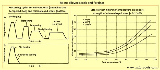
Fig 6 Micro-alloyed steels and forgings
Effects of micro-alloying elements
Carbon – Most of the micro-alloyed steels developed for forging have carbon contents ranging from 0.3 % to 0.5 %, which is high enough to form a large amount of pearlite. The pearlite is responsible for substantial strengthening. This level of carbon also decreases the solubility of the micro-alloying constituents in austenite.
Niobium, vanadium, and titanium – Formation of carbo-nitride precipitates is the other major strengthening mechanism of micro-alloyed forging steels. Vanadium, in amounts ranging from 0.05 % to 0.2 %, is the most common micro-alloying addition used in forging steels. Niobium and titanium enhance strength and toughness by providing control of austenite grain size. Frequently niobium is used in combination with vanadium to achieve the benefits of austenite grain size control (from niobium) and carbo-nitride precipitation (from vanadium).
Manganese – Manganese is used in relatively large amounts (1.4 % to 1.5 %) in many micro-alloyed forging steels. It tends to reduce the cementite plate thickness while maintaining the inter-lamellar spacing of pearlite developed. Hence, high manganese levels require lower carbon contents to retain the large amounts of pearlite required for high hardness. Manganese also provides substantial solid solution strengthening, enhances the solubility of vanadium carbonitrides, and lowers the solvus temperature for these phases.
Silicon – The silicon content of most commercial micro-alloyed forging steels is around 0.3 %. Some grades contain upto 0.7 %. Higher silicon contents are associated with significantly higher toughness, apparently because of an increased amount of ferrite relative to that formed in ferrite-pearlite steels with lower silicon contents.
Sulphur – Many micro-alloyed forging steels, particularly those needed for use in automotive forgings in which machinability is critical, have relatively high sulphur contents. The higher sulphur contents contribute to their machinability, which is comparable to that of quenched and tempered steels.
Aluminum and nitrogen – As in hardenable fine-grain steels, aluminum is important for austenite grain size control in micro-alloyed steels. The mechanism of aluminum grain size control is the formation of aluminum nitride particles. It has been shown that nitrogen is the major interstitial component of vanadium carbo-nitride. For this reason, moderate to high nitrogen contents are needed in vanadium containing micro-alloyed steels to promote effective precipitate strengthening.
Controlled Forging
The concept of grain size control has been used for many years in the production of flat rolled products. Particularly in plate rolling, the ability to increase austenite recrystallization temperature using small niobium additions is well known. The process used to produce these steels is usually referred to as controlled rolling. The benefits of austenite grain size control are not, of course, limited to flat rolled products. Although the higher finishing temperatures needed for rolling of bars limit the usefulness of this approach to micro-structural control, finishing temperatures for micro-alloyed bar steels is nonetheless to be controlled.
It has been shown that, although strength is not significantly affected by finishing temperature, toughness of vanadium-containing micro-alloyed steels decreases with increasing finishing temperature. This effect is shown in Fig 6, which compares Charpy V-notch impact strength for a micro-alloyed steel finished at three temperatures. This detrimental effect of a high finishing temperature on impact toughness also carries over to forging operations, that is, the lower the finish temperature in forging, the higher the resulting toughness, and vice versa. After extensive testing, it has been shown that the finishing temperature for forging if reduced to near 1000 deg C, results in impact properties equal to or better than those of hot rolled bar. It is also shown that rapid induction preheating is beneficial for micro-alloyed forging steels, and that cost savings of 10 % (for standard micro-alloyed forgings) to 20 % (for resulphurized grades) are possible.
Lower finishing temperatures, however, take their toll in terms of higher required forging pressures (and thus higher machine capacities needed) and increased die wear. The improved toughness resulting from lower finishing temperatures, as well as any cost savings which can be achieved as a result of the elimination of heat treatment, is to be weighed against the cost increases caused by these factors.
Micro-alloyed cold heading steels -Steels used in the production of high-strength fasteners by cold heading have been earlier produced from quenched and tempered alloy steels. To obtain sufficient strength with adequate ductility needed six processing steps. Recent developments have led to the use of micro-alloyed niobium-boron steels which need no heat treatment. These steels make use of niobium and boron additions to develop bainitic structures with high work-hardening rates. In most cases they use the deformation of cold heading to achieve the required strength levels without heat treatment.
製造プロセス