


Metal 3D Printing:A Definitive Guide(2021)
金属3D印刷は、あらゆる面で急速に進歩しています。 :技術はより高度になり、印刷速度は向上し、これまで以上に幅広い工業材料が存在します。これらの進歩は、テクノロジーのエキサイティングな新しいアプリケーションを切り開いています。
ただし、利用可能なテクノロジーを把握し、それらを既存のワークフローに統合することは、多くの企業にとって課題となる可能性があります。
このガイドは、現在利用可能なテクノロジーから、テクノロジーの利点、制限、および主要なアプリケーションまで、金属3D印刷をよりよく理解するのに役立つことを目的としています。
金属3D印刷:テクノロジー
現在市場に出回っているさまざまな金属3D印刷技術があります。それぞれに利点と制限がありますが、すべてが金属部品をレイヤーごとに作成するという基本的な3D印刷の原則によって統合されています。
一般的に使用される金属3D印刷技術には、次のものがあります。
- パウダーベッドフュージョン
- 直接エネルギー堆積
- 金属バインダーの噴射
- 超音波シートラミネーション
パウダーベッドフュージョンテクノロジー
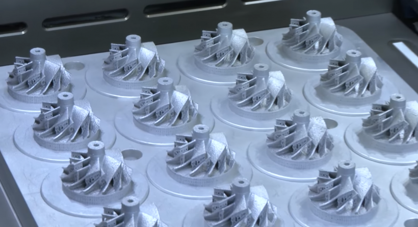
すべての金属3D印刷技術の中で、金属粉末ベッドフュージョンはおそらく最も確立されています。
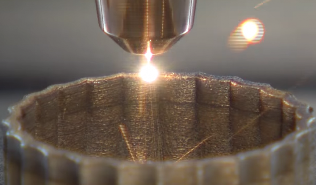
粉末床融合技術を使用すると、粉末金属の層が機械の構築プラットフォームに均等に分散され、レーザーまたは電子ビームのいずれかのエネルギー源によって選択的に融合されます。
パウダーベッドフュージョンカテゴリに分類される2つの主要な金属3D印刷プロセスがあります:
- 選択的レーザー溶融(SLM)/直接金属レーザー焼結(DMLS)
- 電子ビーム溶解(EBM)
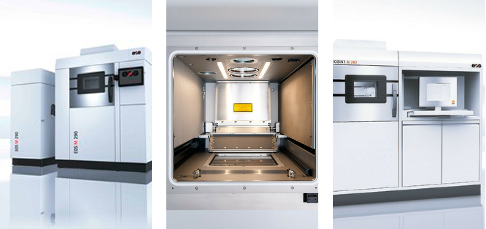
選択的レーザー溶融および直接金属レーザー焼結
IDTechEx Researchのレポートによると、SLMとDMLSは最も支配的な金属3D印刷技術であり、DMLSは世界最大の設置ベースを持っています。
SLMとDMLSの両方で、強力で微調整されたレーザーが金属粉末の層に選択的に適用されます。このようにして、金属粒子が融合して部品を作成します。
両方のテクノロジーの重要な要件は、アルゴンなどの不活性ガスで満たされた密閉型ビルドチャンバーです。これにより、金属粉末の酸素汚染が防止され、印刷プロセス中に正しい温度を維持するのに役立ちます。
電子ビーム溶解
パウダーベッドフュージョンファミリーのもう1つの3D印刷プロセスは、電子ビーム溶解(EBM)です。 EBMは、金属粉末も溶融して完全に緻密な金属部品を作成するという点でSLMと同様に機能します。
粉末の汚染と酸化を防ぐために、EBMプロセスは真空環境で行われます。
SLM / DMLSテクノロジーとEBMテクノロジーの主な違いは、エネルギー源です。EBMシステムは、レーザーの代わりに、金属粉末の層を溶かすための熱源として高出力の電子ビームを使用します。
EBMはまた、SLMやDMLSと比較した場合、精度の低い金属部品を製造する傾向があります。これは、SLMプロセスの層の厚さが通常EBM(50〜200ミクロン)よりも薄い(20〜100ミクロン)ため、より正確な印刷が得られるためです。
電子ビームは通常、レーザーよりも強力であるため、EBMは、ジェットエンジンやガスタービンなどの非常に要求の厳しい用途向けの部品を作成するために、高温の金属超合金とともに使用されることがよくあります。製造される金属部品は高密度であるため、航空宇宙産業に最適です。
EBMシステムの高コストは、このテクノロジーへの投資を検討している企業にとって考慮すべきことです。さらに、この技術は電荷に依存しているため、EBMはチタンやクロムコバルト合金などの導電性金属でのみ使用できます。
SLM / DMLSであろうとEBMであろうと、Powder Bed Fusionテクノロジーで製造されたすべての金属部品には、何らかの形の後処理が必要になります。後処理は、部品の美観を向上させるだけでなく、その機械的特性を向上させ、特に要求の厳しいアプリケーションの場合、正確な設計パラメータを満たすために必要です。
直接エネルギー沈着
[画像提供:Hybrid Manufacturing Technologies ]
直接エネルギー蒸着(DED)は、金属材料がノズルからビルドプラットフォームに蒸着されるときに、レーザーまたは電子ビームで金属材料を溶かすことによって機能します。通常、DEDマシンは材料の堆積速度が高く、粉末またはワイヤーの形の金属材料を処理できるため、ニアネット形状の高密度部品を作成できます。
通常、小さいが高精度のコンポーネントを生成するパウダーベッドフュージョンプロセスとは対照的に、一部の独自のDEDメソッドは、より大きな金属部品を生成できます。
一例として、米国企業のSciaky独自の電子ビーム積層造形(EBAM)技術があります。これは、長さが6メートルを超える部品を製造できると言われています。
DEDテクノロジーは、タービンブレードや射出成形ツールインサートなど、従来の製造方法では修復が困難または不可能な損傷部品の修復に最適です。
金属バインダーの噴射
金属バインダー噴射は、市場で入手可能な最も費用効果の高い金属3D印刷技術の1つです。
紙へのインクジェット印刷と同様に、メタルバインダージェッティングではプリントヘッドを使用します。このプリントヘッドはビルドプラットフォーム上を移動し、金属粉末の層に結合剤の液滴を堆積させます。このプロセスにより、金属粒子が融合して部品が作成されます。
複数のプリントヘッドを使用して、印刷プロセスを高速化できます。
金属バインダー噴射機は、より速い印刷速度と大量の印刷を提供します。また、粉末床システムよりも大幅に安価になる傾向があります。
ただし、印刷プロセスの性質上、メタルバインダージェットを使用して製造された部品は、機械的特性が制限されています。印刷プロセス中にバインダーが燃え尽きるため、多孔性が高くなります。
その結果、部品は最終的に使用する前にかなりの後処理が必要になります。これらのステップには、成形品を硬化させるための硬化、および気孔率を減らして強度を高めるための焼結と青銅の浸透が含まれます。
超音波シートラミネート
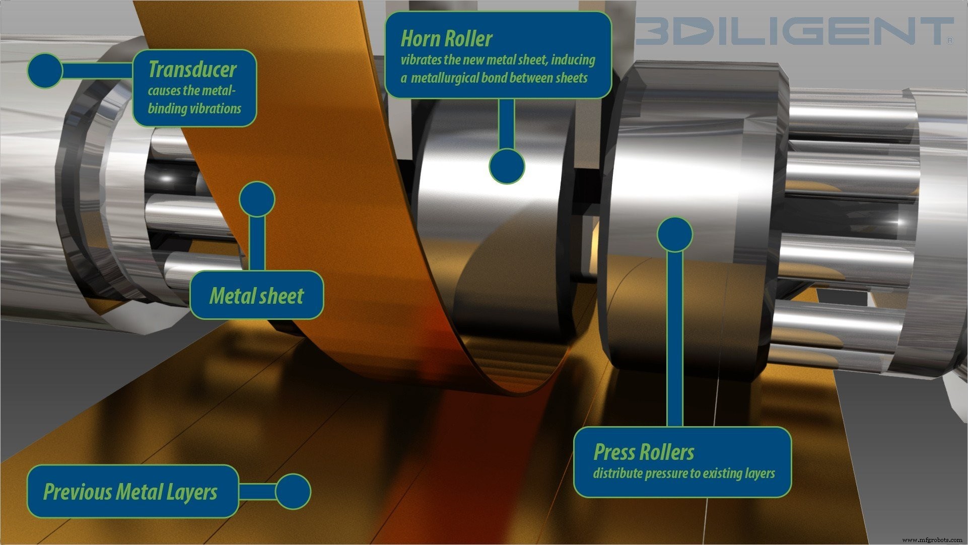
超音波シートラミネートは、低温ハイブリッド金属積層造形プロセスです。
この技術は、圧力下で超音波振動と一緒に薄い金属箔を溶接することによって機能します。印刷プロセスが完了すると、CNCフライス盤が適用され、余分な材料がすべて除去され、パーツが仕上げられます。
低温プロセスであるため、超音波シートラミネーションは金属材料を溶かしません。このプロセスでは、異なる種類の金属を融合させることもできます。
この技術の主な利点は、その低コスト、高速印刷速度、およびさまざまな金属から埋め込まれた電子機器とセンサーを備えた部品を作成できることです。
新しい金属3D印刷プロセス
金属3D印刷の急速な進化に伴い、ハードウェアメーカーは絶えず新しいプロセスの開発を模索しています。以下に、速度とコストの両面で金属3D印刷に革命を起こす可能性のある、いくつかの新しく開発された金属3D印刷技術の概要を示します。
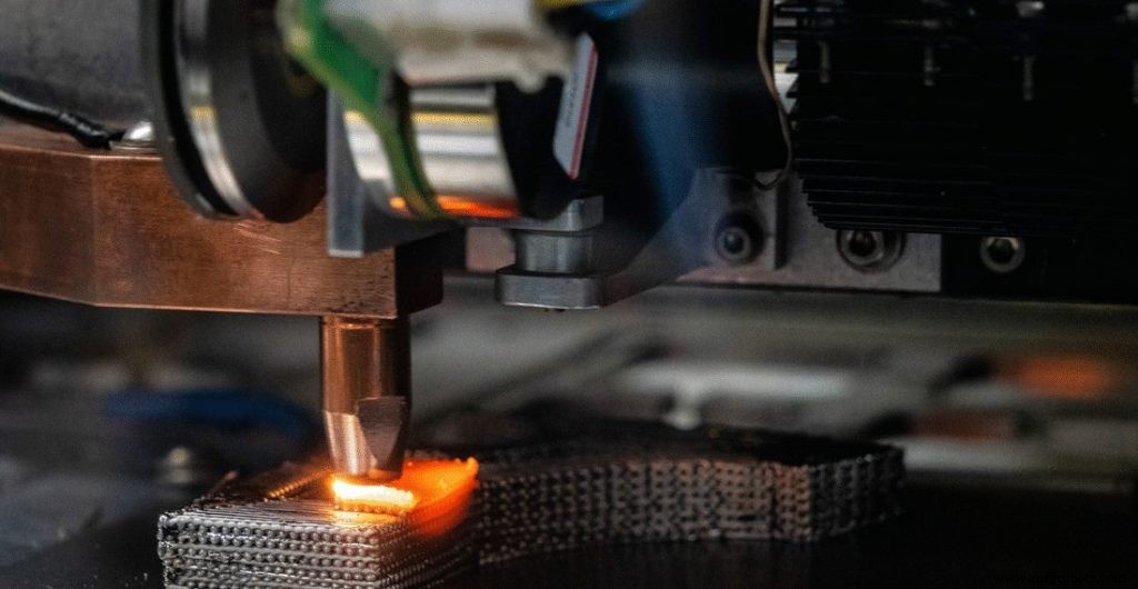
押し出しベースの金属3D印刷
金属フィラメントの押し出しによって部品を追加的に製造することは、比較的新しいアプローチです。
この分野で活動している2つの最も著名な企業は、MarkforgedとDesktopMetalです。両社は、2017年に最初に自社の金属3D印刷システム(MarkforgedのMetalXおよびDesktopMetalのStudioSystem)を発表しました。
押し出しベースの金属3D印刷は、熱溶解積層法(FDM)と同様に機能します。この場合、フィラメントが加熱され、ノズルから押し出されて、層ごとにパーツが作成されます。
ただし、FDMで使用されるプラスチックフィラメントとは異なり、金属押出成形では、プラスチックバインダーに包まれた金属粉末またはペレットで作られたフィラメントが使用されます。
パーツが印刷されると、それは「グリーン状態」のままであり、追加の後処理ステップを実行する必要があります。残りのプラスチックを焼き尽くすための脱バインダーと、金属粒子を融合させるための焼結です。
押し出しベースの金属3D印刷は、最も手頃な金属添加剤製造プロセスの1つです。これは、一部には、粉末床プロセスで使用される金属粉末よりも大幅に安価な金属射出成形(MIM)材料を使用しているためです。
マテリアルジェット
マテリアルジェッティングはインクジェット印刷プロセスであり、プリントヘッドを使用して、液体の形で光反応性材料をビルドプラットフォームにレイヤーごとに堆積します。
マテリアルジェッティングは通常、高精度のフルカラープラモデルを作成するためのプロトタイピングテクノロジーとして使用されてきました。
しかし、ある会社は金属3D印刷の技術の可能性を認識しています。イスラエルの会社、XJetは、高レベルのディテールと仕上げを実現できる金属用の新しいインクジェット技術を開発しました。
XJetのNanoParticleJetting™(NPJ)テクノロジーは、プリントヘッドを使用して、液体製剤に懸濁した金属インクを堆積させます。このプロセスは、加熱されたチャンバー内で行われます。
金属インクが堆積すると、それらは高温のビルディングトレイに堆積し、液体製剤を蒸発させて金属粒子のみを残します。粒子には結合剤の小さなコーティングが施されているため、3つの軸すべてで粒子を互いに結合させることができます。
印刷が完了すると、部品はオーブンに移され、そこで焼結プロセスが行われます。この技術は、機能的なプロトタイピングと中小規模の金属部品のオンデマンド製造の両方に使用できます。
メタルジェット(HP)
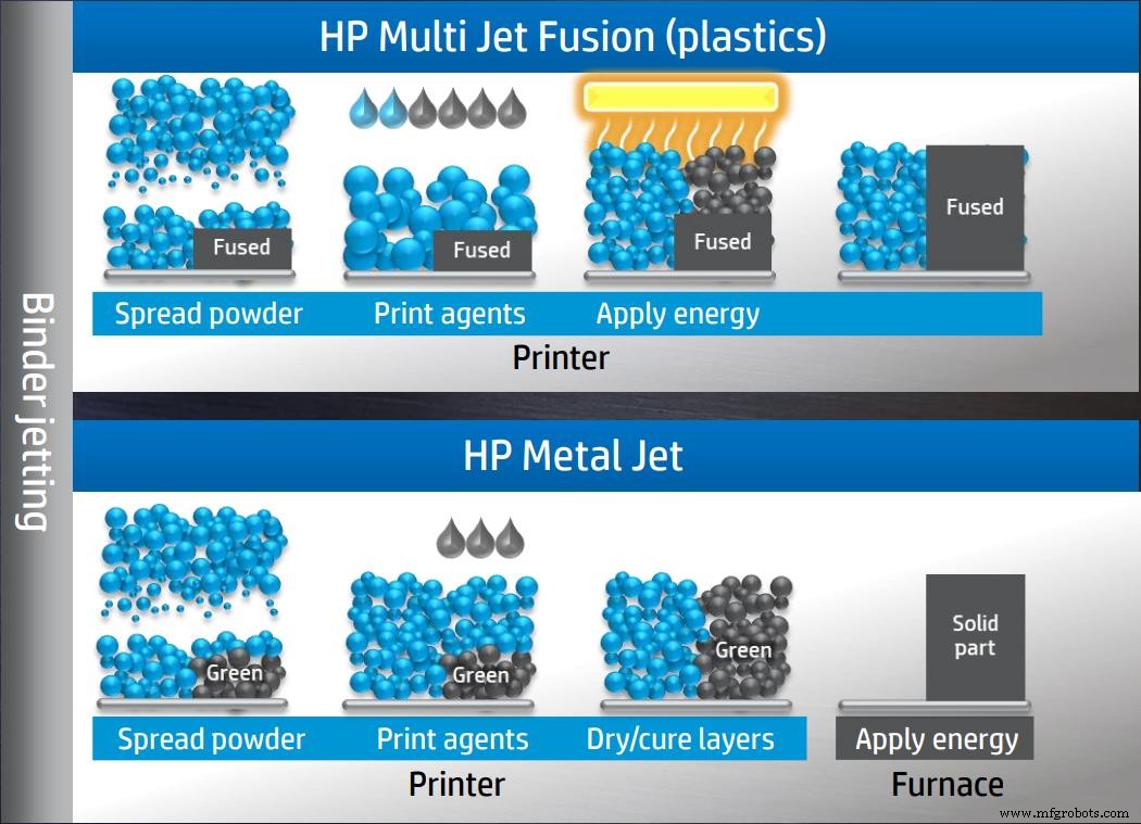
HPは、ポリマーマルチジェットフュージョンシステムの発売により、2016年に3D印刷市場に参入することで最初に波を起こしました。 2018年、同社は新しい金属3D印刷システムであるMetal Jetを発表することで、バインダー噴射技術をさらに一歩進めました。
Metal Jetシステムは、HPのバインダー噴射プロセスに基づいており、より高速で安価な印刷を可能にするために拡張されています。
他のバインダー噴射機と同様に機能しますが、このシステムは、HPのラテックスインクテクノロジーを利用して開発された独自のバインダーを使用しています。この新しいバインダー配合により、部品の焼結がより速く、より低コストになり、はるかに簡単になると言われています。
さらに、Metal Jetは金属射出成形(MIM)粉末を使用しており、ASTM規格に適合する等方性部品を製造できます。
この技術の重要な特徴の1つは、プリントヘッドの量の増加です。これにより、Metal Jetは、現在市場に出回っている同等のバインダーおよびレーザー焼結機よりも最大50倍生産性が高いと言われています。
ジュール印刷(デジタル合金)
商用リリースは2020年までではありませんが、DigitalAlloysの特許取得済みのジュール印刷技術はここで言及する価値のあるもう1つの金属3D印刷プロセスです。
ジュール印刷は、粉末ではなく金属線を使用する高速技術です。
金属ワイヤーは、精密ワイヤーフィードを備えた精密モーションシステムに供給されます。ワイヤが配置されると、電流がワイヤを通過し、続いてプリントベッドと部品自体に流れます。プリントヘッドが動くと、金属線が電流によって溶け、金属の液滴が融合して最終部品を形成します。
ジュール印刷技術は、ニアネットシェイプ部品の製造を可能にすると言われており、自動車、航空宇宙、消費財業界の工具やその他の用途に使用できます。
MELD(MELD Manufacturing)
MELD Manufacturing Corporationは、金属部品を製造するための新しい固体金属3D印刷プロセスを開発しました。ソリッドステートであるということは、印刷プロセス中に金属材料を溶かす必要がないことを意味します。
代わりに、このプロセスでは、金属材料を中空の回転ツールに通します。そこでは、極度の圧力と摩擦によって、追加される材料と、すでに堆積されている材料が変形します。
このプロセスにより、製造された部品の強度と耐食性などの機械的特性が保証されます。
MELDテクノロジーで印刷された部品は完全に緻密であり、その後の熱処理は必要ありません。さらに、このテクノロジーは部品の作成だけでなく、既存のコンポーネントのコーティングや修理にも適しています。
金属3D印刷のビジネスケースを作成する
金属3D印刷は、従来の製造プロセスでは不可能なレベルの複雑さとカスタマイズを提供することにより、部品の製造方法を変革する可能性を秘めています。
金属3D印刷に投資するかどうかを決定するときは、会社がこのテクノロジーから利益を得ることができるかどうかを評価することが重要です。以下に、金属3D印刷の主な利点のいくつかを概説します。
時間の節約とコストの削減
まず、3D印刷により、高価な工具や金型が不要になり、メーカーは高価で時間のかかるセットアップコストを削減できます。第二に、設計から製造に移行する機能により、リードタイムを数週間または数か月から数日に大幅に短縮できます。
最後に、パーツアセンブリを3D印刷で統合する機能は、労力とコストを大幅に節約するのに役立ちます。
無駄の少ない材料
従来のサブトラクティブ製造方法では、大量の材料の無駄が発生します。ある調査によると、CNCフライス盤を使用して金属ブロックから材料を切断すると、95%もの材料の無駄が発生する可能性があります。
それに比べて、金属3D印刷プロセスでは、必要な場合にのみ材料が焼結または溶融されるため、廃棄物の発生がはるかに少なくなります。場合によっては、未焼結の金属粉末を再利用することもできます。
その結果、3D印刷での材料の使用は非常に効率的であり、材料のスクラップ率は通常5%未満です。
より優れた設計革新を実現する
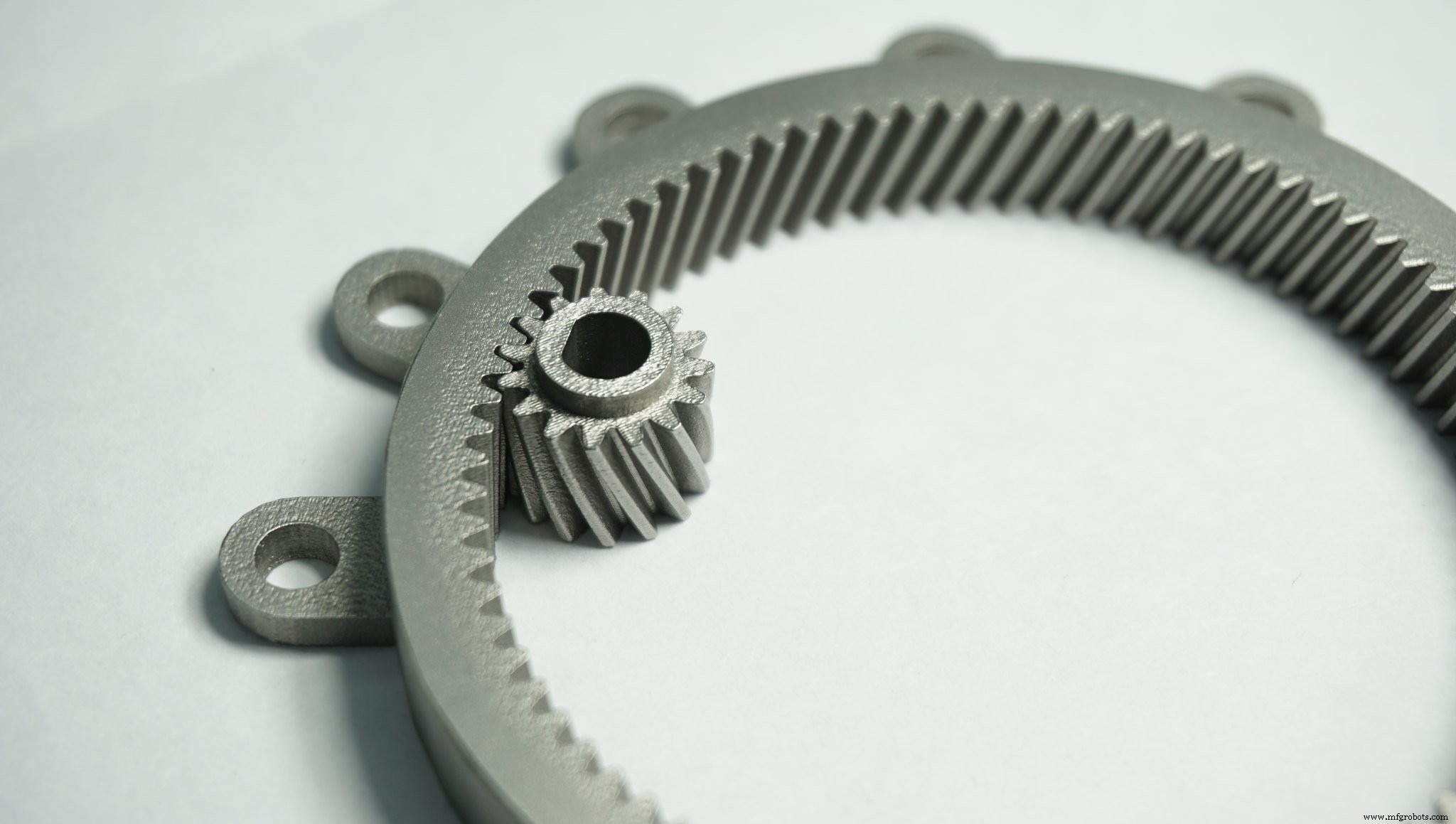
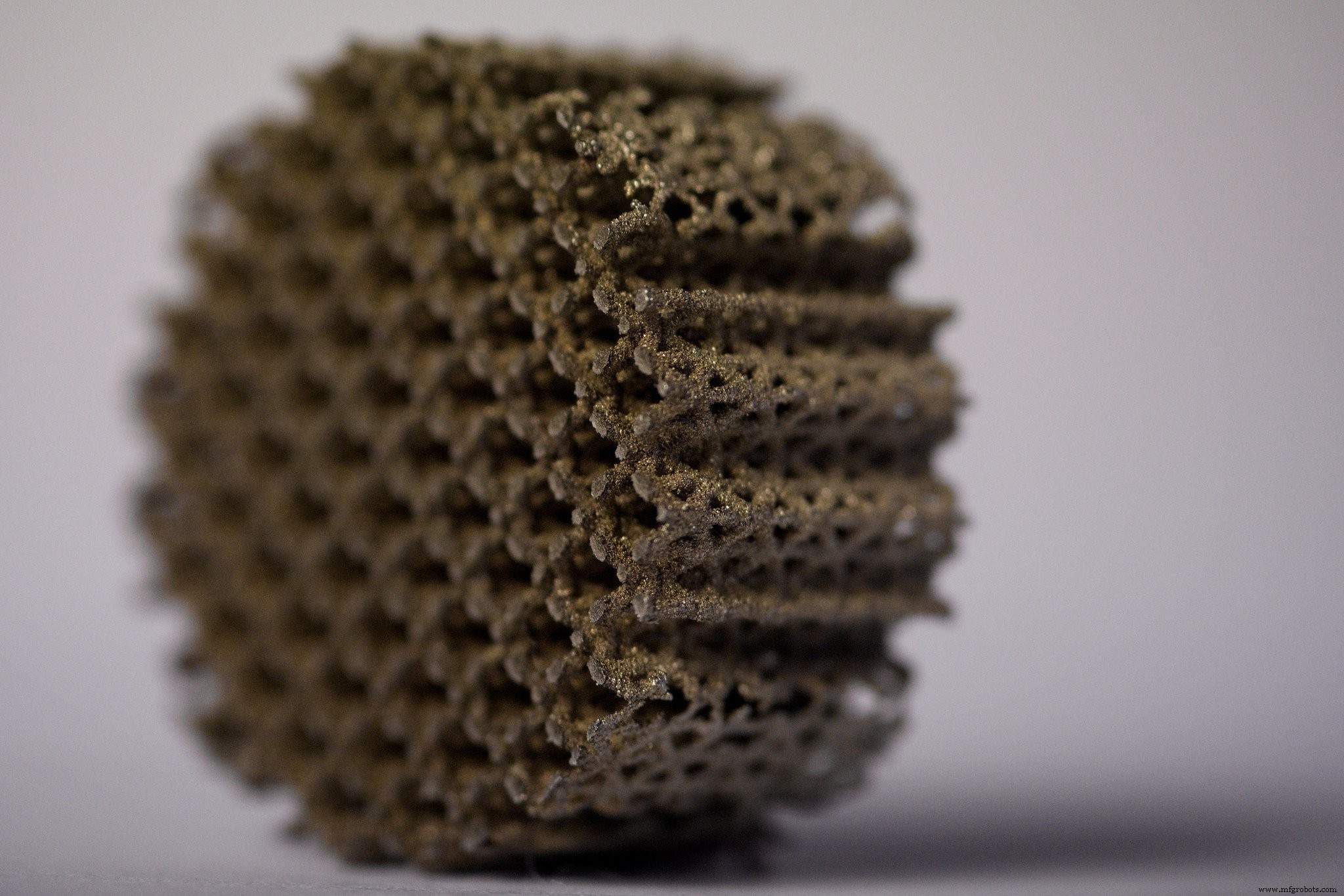
金属3D印刷は、複雑な形状を作成するために使用でき、製造で可能なことの限界を押し広げます。これらの複雑な設計は、従来のプロセスよりもコスト効率よく製造できます。
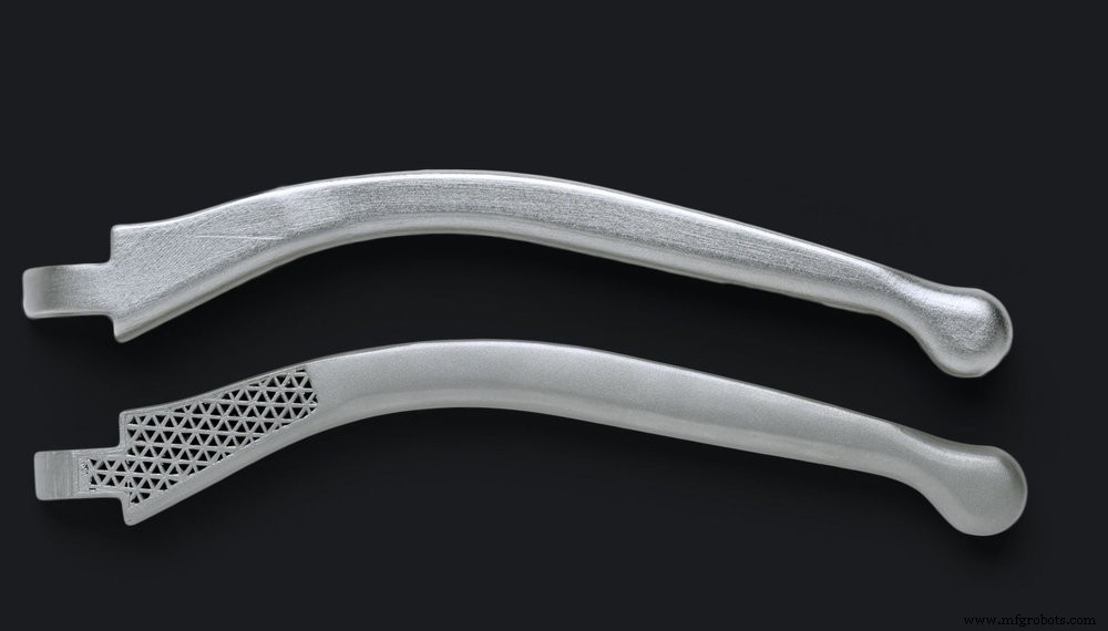
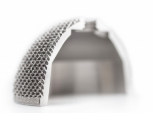
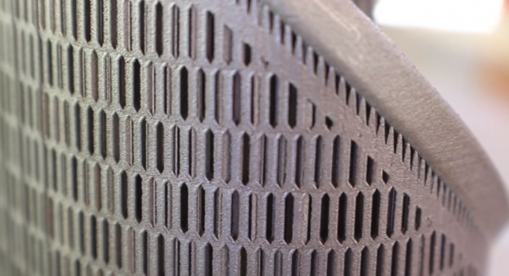
トポロジー最適化やジェネレーティブデザインなどの設計ツールと組み合わせることで、3D印刷を使用して、機能性と機械的特性が強化された軽量の金属部品を作成できます。
したがって、これらのソフトウェア設計ツールは、無数の新しい革新的な設計の可能性を解き放つのに役立ちます。たとえば、格子構造を設計に組み込んで、金属部品の重量を減らし、車両や航空機の性能を向上させることができます。
費用効果の高い少量生産
3D印刷により、少量生産が経済的に実行可能になります。
工具費が高いため、従来の製造方法は、部品を少量生産するために実装するのに非常に費用がかかる可能性があります。
対照的に、3D印刷は工具を必要としないため、少量生産の場合はより費用効果の高いオプションです。この重要な例の1つは、カスタマイズされた部品の場合です。この場合、製品は1回限りまたは少量のバッチの一部として製造する必要があります。
3D印刷を使用して、オンデマンドで部品を作成することもできます。たとえば、企業は必要に応じて社内で3D印刷ツールとスペアパーツを使用できます。これにより、実地棚卸に部品を備蓄する必要性が減り、ロジスティクスとサプライチェーン全体が簡素化されます。
金属3D印刷の課題
金属3D印刷の利点は明らかですが、このテクノロジーをうまく実装するには課題があります。以下では、金属3D印刷市場が現在直面している主要な課題のいくつかについて説明します。
高コスト
3Dプリンターの価格は、過去10年間で大幅に下落しましたが、金属AMシステムのコストは、このテクノロジーへの投資を検討している企業にとって依然として主要な課題の1つです。
現在、金属製の3Dプリンターは、数十万ドル、さらには100万ドル以上の費用がかかる可能性があります。
同時に、市場で入手可能な現在の金属材料は一般に非常に限られており、コストは従来の金属製造で使用される金属よりも大幅に高くなっています。
とはいえ、今後数年間で、金属材料科学の進歩により、3D印刷可能な金属の選択肢が広がり、コストが削減されると期待しています。
より複雑な
金属3D印刷には複数の変数が関係しているため、ポリマー3D印刷よりもはるかに複雑なプロセスになります。現在、多くの企業は、社内で金属3Dプリンターを正常に運用するために必要な専門知識を欠いています。
このテクノロジーを開始するための1つの可能な方法は、金属3D印刷サービスプロバイダーとのコラボレーションです。サービスビューローは、適切な金属AM技術と材料を選択するための専門知識を提供できます。
AMテクノロジーを社内に持ち込もうとしている企業にとって、AM戦略の開発と実装は、この旅の重要な最初のステップになります。
部品品質の確保
部品の品質とプロセスの再現性は、メーカーにとって重要な懸念事項です。金属3D印刷に関しては、部品の品質に影響を与える可能性のあるさまざまな変数があります。これらの変数は、設計からビルドの準備、後処理まで、AMワークフロー全体に及びます。
ただし、これらの変数を制御して、再現性のある高品質の金属部品を実現することは、依然として課題です。
資料
金属は、2012年以来3D印刷材料市場で最も急成長しているセグメントです。
金属3D印刷プロセスでは、高品質の金属材料を使用します。それらは通常、粉末の形で製造され、粒子の形状やサイズ、粉末の密度などの特定の特性を満たす必要があります。
従来の製造プロセスと比較して、利用可能な3D印刷可能な金属の範囲は限られたままです。
これは、金属3D印刷技術に適合または製造された特殊な材料の開発には、何年もかかる可能性があるためです。
ただし、DEDのような一部のプロセスでは、元々従来のプロセス用に開発された金属を、たとえばワイヤーの形で使用できます。
現在、金属3D印刷で最も一般的に使用されている材料には、アルミニウム、チタン、ステンレス鋼などの軽量金属が含まれます。
ただし、高融点金属およびコバルトクロム合金の使用も拡大しており、主に航空宇宙および石油およびガス産業での用途に牽引されています。
以下の表では、より一般的な金属3D印刷材料とその一般的な用途を示しています。
(AlSi10Mg、AlSi12、AlSi12Mg合金、Scalmalloy)
主な用途:アルミニウムは、軽量で幾何学的に複雑な部品の製造に使用でき、特に自動車および航空宇宙産業で使用されます。 チタン
商業的に純粋(グレード1および2)
チタン合金Ti6Al4V(グレード5)
チタン合金Ti6AL-4V ELI(グレード23)
主な用途:チタンは、モータースポーツ、航空、医療/歯科用途に最適です。 ステンレス鋼
(17-4PHおよび316L合金)
主な用途:ステンレス鋼は、航空宇宙、石油およびガス、食品加工、および医療業界で特にそのマークを見つけました。 コバルトクロム合金(CoCrMo)
主な用途:医療(膝関節や股関節を含む人工関節としての外科用インプラント)および歯科。この金属は、ガスタービンや風力タービンの部品、およびエンジンコンポーネントの製造にも使用されています。 ニッケル合金(インコネル625、インコネル713、インコネル718、インコネル738、ハステロイX)
主な用途:ニッケル合金は、航空宇宙、化学プロセス、電力業界、およびジェットエンジンのガスタービンブレード内の高温用途に最適です。 銅ベースの合金
主なアプリケーション:熱管理アプリケーション(マイクロ熱交換器など)、電気工学、工具インサートマルエージング鋼(工具鋼)
主な用途:工具(ダイカストおよび射出成形ツールのコアとインサート)、機能的なプロトタイプ高融点金属(タンタル、ニオブ、タングステン)
主な用途:この金属グループは、ミサイルやロケットスラスターのノズル、バルブ、マニホールドなどの高応力用途に役立ちます。インプラント(タンタル)貴金属(金、銀、プラチナ)
主な用途:貴金属は、アクセサリー(宝飾品や時計)、歯科(クラウン、インレー、アンレー)などのニッチな用途に使用されます
機械
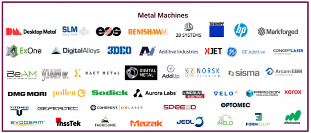
金属3D印刷の増加に伴い、市場で入手可能な金属3Dプリンターの数は拡大しています。
2018 Wohlers Reportによると、2017年の金属AMシステムの売上は80%増加し、市場に参入する金属AMシステムメーカーの数が増加しました。
ダウンロード可能な表に、粉末床技術、DED、バインダージェット、および押出成形ベースの金属3D印刷を使用した、金属3Dプリンターの主なメーカーをまとめました。網羅的なリストではありませんが、市場に出回っている主要な機械メーカーの概要を示しています。
LaserForm CoCr(B)または(C)DMLS&SLM3D SystemsProX DMP 200140 x 140 x 100 mmLaserForm Ni625(B)
LaserForm 17-4PH(B)
LaserForm Maraging Steel(B)
LaserForm 316L(B)
LaserForm CoCr(B)または(C)
LaserForm AlSi12(B)DMLS& SLM3D SystemsProX DMP 300250 x 250 x 300 mmLaserForm 17-4PH(B)、
LaserForm Maraging Steel(B)、
LaserForm CoCr(B)
LaserForm AlSi12(B)
(コバルトクロム合金、ステンレス鋼、マレージ鋼、アルミニウム合金(AlSi12))DMLS&SLM3D SystemsProX DMP 320275 x 275 x 380 mmLaserFormマレージング鋼(A)
LaserForm 17-4PH(A)
LaserForm Ni625( A)
LaserForm AlSi10Mg(A)
LaserForm CoCrF75(A)
LaserForm Ti Gr5(A)
LaserForm Ti Gr23(A)
LaserForm Ti Gr1(A)
LaserForm 316L(A)
LaserForm Ni718(A)
(チタン合金、アルミニウム、ニッケル合金、ステンレス鋼、コバルトクロム、マレージ鋼)DMLS&SLM3D SystemsDMP Factory 500 Solution500 x 500 x 500mm DMLS&SLMEOSEOS M 100100 mm x 95mmステンレス鋼316L
ステンレス鋼316L
チタンTi64DMLS&SLMEOSEOS M 290250 x 250 x 325mmアルミニウム
コバルトクロム
マルエージング鋼
ステンレス鋼合金
ステンレス鋼合金DMLS&SLMEOSEOS M 400400 x 400 x 400 mmアルミニウム、マルエージング鋼、ニッケル合金、チタン合金DMLS&SLMEOSEOS M 400-4400 mm x 400 mm x 400 mmアルミニウム、ニッケル合金、マルエージング鋼、ステンレス鋼、チタンTi64、チタングレード2 DMLS&SLMEOSEOSINT M 280250 mm x 250 mm x 325 mmEOS MaragingSteel MS1
EOS CobaltChrome MP1
EOSステンレス鋼GP1
EOSステンレス鋼PH1
EOSステンレス鋼316L
EOSステンレス鋼Ti64
EOSステンレス鋼Ti64ELI
EOSアルミニウムAlSi10Mg
EOSニッケル合金IN718
EOSニッケル合金IN625
EOS NickelAlloy HX DMLS&SLMEOSPRECIOUS M 08080 x 80 x 95 mm金、銀、プラチナ、パラジウム合金DMLS&SLMRenishawRenAM250250 mm x 250 m m x 300 mmTi6Al4V ELI
AlSi10Mg
ステンレス鋼316L
工具鋼
ニッケル合金
コバルトクロム合金。 DMLS&SLMRenishawRenAM400250mm×250mm×300mmTi6Al4V ELI
AlSi10Mg
ステンレス鋼316L
工具鋼
ニッケル合金
コバルトクロム合金。 DMLS&SLMRenishawRenAM 500M250mm×250mm×350mmTi6Al4V ELI
AlSi10Mg
ステンレス鋼316L
工具鋼
ニッケル合金
コバルトクロム合金。 DMLS&SLMRenishawRenAM 500Q250 mm x 250 mm x 350 mmTi6Al4V ELI
AlSi10Mg
ステンレス鋼316L
工具鋼
ニッケル合金
コバルトクロム合金。 DMLS&SLMSLMソリューションSLM 125125 x 125 x75ステンレス鋼
ツールスチール
コバルト-クロム
インコネル
アルミニウム
チタンDMLS&SLMSLMソリューションSLM 280 2.0280 x 280 x350ステンレス鋼
br />ツールスチール、
コバルト-クロム
スーパーアロイ
アルミニウム
チタンDMLSおよびSLMSLMソリューションSLM500500 x 280 x325アルミニウム合金
ステンレス合金
ツールスチール
チタン
インコネル
コバルト-クロムDMLS&SLMコンセプトレーザー(GE添加剤)Mlab cusing50 x 50 x 80mmステンレススチール
ブロンズ
ゴールド
シルバー合金
コバルト-クロム合金DMLSおよびSLMコンセプトレーザー(GE添加剤)Mlab cusing R50 x 50 x 80mmステンレス鋼
ブロンズ
ゴールド
銀合金
コバルト-クロム合金
チタンおよびチタン合金DMLSおよびSLMコンセプトレーザー(GE添加剤)Mlab cusing 200R100 x 100 x 100mmステンレス鋼
アルミニウム
チタン合金
商業的に純粋なチタングレード2
マージング鋼
ブロンズ
ステンレス鋼、
ニッケル基合金
コバルト-クロム合金DMLSおよびSLMConceptレーザー(GE添加剤)M1 cusing250 x 250 x 250 mmステンレス鋼
マージング工具鋼、
ステンレス工具鋼
ニッケル基合金
コバルト-クロム合金DMLSおよびSLMコンセプトレーザー(GE添加剤)M2 cusing250 x 250 x 350mmステンレス鋼
アルミニウム合金
チタン合金
純粋なチタングレード2
マレージング鋼
耐食性析出硬化鋼
析出硬化ステンレス鋼
ニッケル基合金
コバルト-クロム合金DMLSおよびSLMコンセプトレーザー(GE添加剤)M2カッシングマルチレーザー250 x 250 x 350mmステンレス鋼
アルミニウム合金
チタン合金
純粋なチタン
マージング鋼
沈殿硬化鋼
ニッケル基合金
コバルトクロム合金DMLSおよびSLMコンセプトレーザー(GE添加剤)MLINE FACTORY500 x 500x最大400mmアルミニウム合金
チタン合金
ニッケル基合金
コバルト-クロム合金DMLSおよびSLMコンセプトレーザー(GE添加剤) )X LINE 2000R800 x 400 x 500 mmアルミニウム(AlSi10Mg)
チタン合金(TiAl6V4)
ニッケル基合金EBMArcam(GE添加剤)Arcam EBM A2X200x200x380 mmTiAl、
ニッケル合金718EBMArcam(GE添加剤) )Arcam EBM Q10plus200 x 200 x 180mmTitanium Ti6Al4V
Cobalt-Chrome EBMArcam(GE Additive)Arcam EBM Q20plus350 x 380mmTitanium Ti6Al4V
Cobalt-Chrome EBMArcam(GE Additive)Arcam EBM Spectra H250 x 250 x 430mmTitanium a )
Alloy 718. DMLS&SLMSismamysint100100 mm x h100 mmCobalt Chrome
貴金属
ブロンズ
鋼合金
ニッケル合金
純銅
銅合金
チタン
アルミニウム合金DMLSおよびSLMSismamysint300300x 400mm貴金属
ブロンズ
コバルトクロム
ステンレス鋼
マージング鋼
ニッケル合金
アルミニウム合金
チタンDMLSおよびSLMDMGMoriLASERTEC 30SLM第2世代300x 300 x300mmアルミニウム
チタン
工具鋼
コバルトクロム
インコネルDMLSおよびSLMXactMetalXM200C127x 127 x 127 mmステンレス鋼、
スーパーアロイ、
コバルトクローム、
Hastelloy®X、
Tooling Steels DMLS&SLMXact MetalXM200S127 x 127 x 127 mmアルミニウムSi10Mg、
ブロンズ、
ステンレス鋼、
スーパーアロイ、
コバルトクローム、
Hastelloy®X、
チタンTi64、
ツーリング鋼DMLSおよびSLMXactMetalXM300C254 x 330 x 330 mmステンレス鋼、
スーパーアロイ、
コバルトクローム、
Hastelloy®X、
ツーリング鋼、
ブロンズDMLS&SLMAddUpFormUp™350350 x 350 x 350mmステンレス鋼、
マレージング鋼、
ニッケル合金、
チタン合金、
アルミニウム合金DMLS&SLMTRUMPFTruPrint 1000100 mm x 100 mm高さステンレス鋼、
工具鋼、
アルミニウム、
ニッケルベース、
コバルトクロム、
銅、
チタン、
貴金属合金DMLS&SLMTRUMPFTruPrint 3000300 mm x 400 mm高さステンレス鋼、
工具鋼、
アルミニウム、
ニッケルベース、
コバルトクロム、
銅、
チタン、
プレ貴金属合金
ブロンズDMLSおよびSLMTRUMPFTruPrint5000300 mm x 400 mm高さステンレス鋼、
工具鋼、
アルミニウム、
ニッケルベース、
コバルトクロム、
銅、
チタン、
貴金属合金DMLS&SLMVELO3DSapphire315mm直径x400 mmInconel 718、チタン(6Al4V)DEDSciakyEBAM®68711x635 x 1600mmチタン
チタン合金
Inconel 718、625、
タンタル、
タングステン、
ニオブ、
ステンレス鋼(300シリーズ)、
アルミニウム、
鋼ジルカロイ、
Copper Nickel,
Nickel Copper DEDSciakyEBAM® 881219 x 89 x 1600 mmTitanium
Titanium alloys
Inconel 718, 625,
Tantalum,
Tungsten,
Niobium,
Stainless Steels (300 series),
Aluminum,
Steel Zircalloy,
Copper Nickel,
Nickel Copper DEDSciakyEBAM® 1101778 x 1194 x 1600 mmTitanium
Titanium alloys
Inconel 718, 625,
Tantalum,
Tungsten,
Niobium,
Stainless Steels (300 series),
Al uminum,
Steel Zircalloy,
Copper Nickel,
Nickel Copper DEDSciakyEBAM®1502794 x 1575 x 1575 mmTitanium, Titanium alloys, Inconel 718, 625, Tantalum, Tungsten, Niobium, Stainless Steels (300 series),
Aluminum, Steel Zircalloy, Copper Nickel, Nickel Copper DEDSciakyEBAM® 3005791 x 1219 mm x 1219 mmTitanium, Titanium alloys, Inconel 718, 625, Tantalum, Tungsten, Niobium, Stainless Steels (300 series),
Aluminum, Steel Zircalloy, Copper Nickel, Nickel Copper DEDOptomecLENS 450100 x 100 x 100 mmTitanium, Nickel, Tool Steel, Stainless Steel, Refractories, Composites, Cobalt, Aluminium, Copper DEDOptomecLENS MR-7300 x 300 x 300 mmTitanium, Nickel, Tool Steel, Stainless Steel, Refractories, Composites, Cobalt, Aluminium, Copper DEDOptomecLENS 850-R900 x 1500 x 900 mmTitanium, Nickel, Tool Steel, Stainless Steel, Refractories, Composites, Cobalt, Aluminium, Copper DEDOptomecLENS 860 Hybrid860 x 600 x 610 mmTitanium, Stainless Steel, Tool Steel, Inconel DEDOptomecLENS C S 600600 x 400 x 400 mmInconel Alloys, Stainless Steels, Titanium Alloys DEDOptomecLENS CS 800800 x 600 x 600 mmInconel Alloys, Stainless Steels, Titanium Alloys DEDBeAMModulo 250400 x 250 x 300Titanium Alloys, Steels, Nickel Alloys, Cobalt Alloys, and more DEDBeAMModulo 400650 x 400 x 400Titanium Alloys, Steels, Nickel Alloys, Cobalt Alloys, and more DEDBeAMMagic 8001200 x 800 x 800Titanium Alloys, Steels, Nickel Alloys, Cobalt Alloys, and more DEDInnsTekMX-600450 x 600 x 350 mmInconel, Steel DEDInnsTekMX-10001,000 x 800 x 650 mmInconel, Steel DEDInnsTekMX-Grande4,000 X 1,000 X 1,000 mmInconel, Steel DEDDMG MoriLASERTEC 65 3D735 x 650 x 560 mm Metal Binder JettingExOneM-Flex400 x 250 x 250 mmStainless steel, bronze, tungsten Metal Binder JettingExOneM-Print800 x 500 x 400 mmStainless steel (420 and 316) Metal Binder JettingExOneInnovent+160 x 65 x 65 mmStainless steel Metal Binder JettingExOneX1 25 PRO400 x 250 x 250 mmSteel (136L, 304 L and 17-4PH), Stainless steels, Inconel 718 and 625, M2 and H11 tool steels, Cobalt chrome, Copper, Tungsten carbide cobalt Metal Binder JettingDigital MetalDM P2500203 x 180 x 69 mmStainless steel (316L, 17-4PH), Titanium Ti6Al4V Metal Binder JettingHPMetal Jet430 x 320 x 200 mmStainless steel powders (developed for metal injection molding) Metal Binder JettingDesktop MetalProduction System337 x 337 x 330 mmAluminium, titanium, high-performance alloys Material ExtrusionDesktop MetalStudio System300 x 200 x 200 mmAlloy steel, Aluminium Carbide, Copper, Heavy alloy, High performance steel, Magnetics, Stainless steel, Super alloy, Titanium, Tool steel Material ExtrusionMarkforgedMetal X300 x 220 x 180 mmStainless Steel, Aluminum, Tool Steel, Inconel, Titanium
Industrial Applications
Metal 3D printing has found its niche in a number of industries, with players in the aerospace, automotive and medical industries at the forefront of driving innovation with the technology.
In this section, we take a look at the most common applications for the technology, as well as key use cases that have unlocked the benefits of metal 3D printing.
Industry Common applications Aerospace Fuel injectors, blades, combustor liners, rocket engine manifolds, brackets, functional prototypes Automotive Air ducts, brackets, uprights, knuckles, turbochargers, suspension assemblies, transmission plates, brake calipers, manifolds Medical and dental Custom-fit dental restorations, such as stages, crowns, and bridges; customised orthopaedic implants (hip, knee, and spinal), surgical tools Industrial goods Tool inserts with conformal cooling channels, industrial pump components, bearings, stators, heat exchangers, impellers, tooling repair
Aerospace
The aerospace industry has been a huge pioneer of metal 3D printing. By using the technology, aerospace companies hope to produce more efficient, lightweight aircraft parts to improve aircraft performance.
Within the aerospace industry, metal 3D printing is used in a range of applications, from functional prototypes to tooling, replacement parts and structural aircraft components.
General Electric
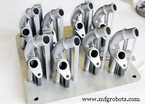
A great example is General Electric (GE), which is extensively using metal 3D printing to make and develop new products. GE’s subsidiary, GE Aviation, is producing fuel nozzles for the LEAP family of jet engines, with an aim to manufacture 100,000 fuel nozzles by 2020.
Having achieved the milestone of 30,000 3D-printed fuel nozzles in October 2018, GE looks like it’s well on its way to fulfilling this goal.
Using advanced design tools and Electron Beam Melting technology, GE’s engineers were able to create a fuel nozzle 25% lighter and 15% more fuel efficient than its traditionally produced counterpart.
The breakthrough in this case is that the fuel nozzle was printed as a single unit, whereas previous models incorporated 20 separate parts which needed to be subsequently assembled.
But GE has not stopped here. The company is also building its GE Catalyst, an advanced turboprop engine that has more than a third of its components 3D printed in various metals.
Similar to its fuel nozzles, the engineers behind the turboprop have achieved considerable part consolidation, reducing the number of parts produced from 855 to just 12. A redesign will also help to reduce the fuel burn of an engine by as much as 20%.
Automotive
Automakers have been using 3D printing since the technology’s early days — Ford Motor Company, for example, notably bought the third 3D printer ever made.
For many years, metal 3D printing has proved to be a cost-effective tool for prototyping and producing jigs and fixtures. However, advancements with the technology mean that more opportunities are opening up for end-part production.
Automotive companies can use metal 3D printing to create lightweight metal parts, leading to enhanced vehicle performance and lower fuel consumption. This is particularly beneficial for the motorsports industry, where 3D-printed car parts can offer racing teams significant performance advantages.
Another area of interest for the industry is also using 3D printing to produce spare parts that are typically produced in low volumes. 3D printing spare parts on demand enables automakers to receive parts at the point of need, reducing inventory costs and increasing agility.
BMW
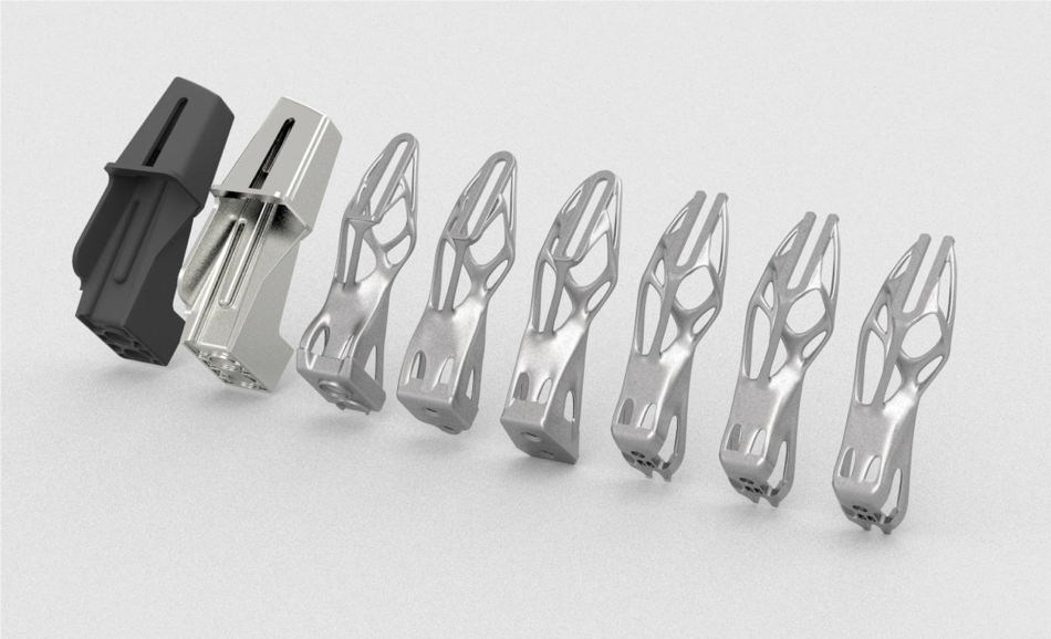
BMW is another company using 3D printing extensively. Most notably, the company has recently moved into the series production of a 3D-printed metal component for its 2018 BMW i8 Roadster vehicle.
Using topology optimisation, designers were able to optimise the vehicle’s roof bracket — a fixture for the folding/unfolding mechanism of the vehicle’s soft top. 3D printed in aluminium alloy powder (AlSi10Mg), the new roof bracket is 44% lighter than its conventionally made counterpart.
Furthermore, engineers optimised the design of the bracket to eliminate support structures. By doing so, the team was able to increase throughput from 51 to 238 of these parts per platform. This makes BMW’s roof bracket the first automotive component to be mass-produced with the help of metal 3D printing.
Bugatti
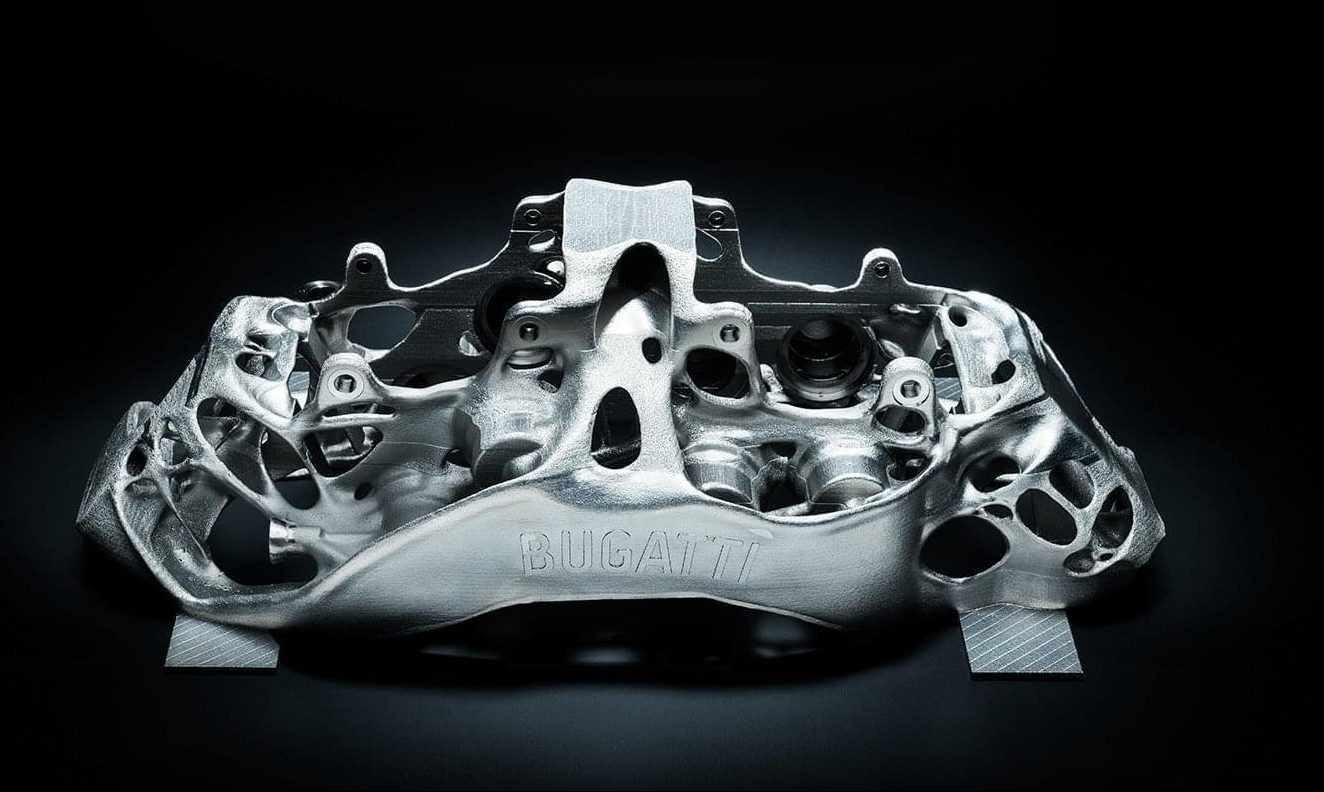
An exciting application of metal 3D printing comes from luxury car manufacturer, Bugatti. The French automaker has developed a 3D-printed brake caliper to be used on its Bugatti Chiron supercar.
An essential part of the braking system, the brake caliper has been made lighter and stronger thanks to 3D printing. Measuring 41 x 21 x 13.6 cm, the part took 45 hours to print using SLM technology and titanium powders.
By using 3D printing, Bugatti also achieved a 40% weight reduction for the caliper, when compared to machined aluminium alternative.
In 2018, the company successfully tested the brake caliper, proving that it can meet extreme strength, stiffness and temperature requirements.
Audi
Audi presents a different business case for metal 3D printing. In this case, the German automaker is using the technology to produce spare parts that are in low demand.
Metal 3D printing allows Audi to produce these parts on demand, producing and supplying spare parts as they are needed. This in turn greatly simplifies logistics and warehousing.
Audi identified that smaller, complex components would be most suited for metal 3D printing. A good example of a component is water adapters, which Audi is already producing for the Audi W12 engine. The company says that the load capacity of the components is comparable to that of parts manufactured using traditional methods.
Medical
In the medical field, metal 3D printing allows highly customised medical devices, like orthopedic implants, to be created.
It’s far from unusual for off-the-shelf orthopaedic implants to be used for replacement surgeries. However, prefabricated implants can sometimes cause problems after the surgery as they don’t always fit properly.
To avoid this, 3D printing is increasingly being used to create customised, patient-specific implants with improved functionality.
For example, implants can be designed with improved porosity and surface texture, facilitating the growth of the tissue around the implant. This level of complexity can only be achieved with 3D printing. SmarTech Publishing predicts that more than 2 million implants will be 3D printed in metal by 2025.
Additionally, metal 3D printing can be used to create hip and knee joint replacements, cranial reconstruction implants and spinal implants.
Lima Corporate
Italian medical device manufacturer Lima Corporate has been bringing additively manufactured hip implants to market for 10 years, using Electron Beam Melting (EBM) technology.
The company developed a technology for 3D printing biocompatible titanium in cellular solid structures that resemble natural bone. Such structures are used to coat an implant, allowing it to be better integrated with human tissue.
The technology is said to have helped almost 100,000 patients, enabling better implant performance and outcomes.
Industrial Goods
When it comes to the design and manufacture of tooling equipment, 3D printing can empower engineers to overcome traditional limitations. This can mean being able to create a mould or core in a matter of days instead of months, significantly reducing lead times.
Within the injection moulding industry, moulds are typically CNC-machined. Here, production costs can range from from $20,000 to hundreds of thousands of dollars. Lead times can last between 2 to 4 months. Additionally, moulds can often require multiple design iterations to achieve the final design, a costly and time-intensive process.
However, metal 3D printing can overcome these inefficiencies in several ways. First, the technology enables rapid design iterations, enabling changes to be made with relative ease.
Second, the performance of tooling aids and components can be enhanced with additive manufacturing.
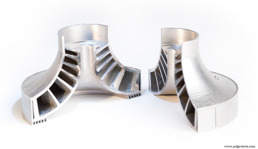
For example, conformal cooling channels, lattice structures, and complex core/cavity shapes, which are too expensive or impossible to manufacture traditionally, can be factored into a mould design and 3D printed.
Conformal cooling channels are particularly beneficial as they help to achieve more homogenous heat transfer within the mould, compared to traditionally drilled straight-line cooling channels, resulting in greater cooling characteristics.
GW Plastics 3D prints moulds with conformal cooling
GW Plastics, US-based mould maker, has invested in hybrid metal 3D printing with the goal of building injection moulds with conformal cooling. One of the key reasons for this investment is faster cycles and better part quality enabled by 3D-printed moulds.
In fact, the company says 3D-printed moulds can save up to 30% of the cycle time by reducing cooling time. Furthermore, metal 3D printing allows GW Plastics to print a mould as a single piece, thus eliminating the need to assemble multiple components.
Post-processing
Post-processing is an unavoidable step when 3D printing metal parts. Post-processing helps to improve the mechanical properties, geometrical accuracy and aesthetics of a part, ensuring that a part meets the required design specifications.
Before printing your part, it’s important to understand the various post-processing methods that can be used to finish a metal part.
In this section, we’ll be looking at some of the main post-processing steps that can help to achieve the necessary finish for metal 3D-printed parts.
Stress relief
High temperatures and subsequent cooling are a common occurrence during the metal 3D printing process. However, when a metal part is subjected to such extreme temperature changes, this can lead to residual stress.
To avoid deformations that can occur as a result of a build-up of residual stress, parts produced with powder bed processes must undergo a stress relieving cycle. The number of stress relief cycles depends on the metal or alloy used to produce a part.
In order to protect the surface of a part from oxidation, the stress relieving heat treatment takes place in an inert (typically argon) atmosphere. Parts are typically heat treated while still attached to the build platform.
During the stress relieving cycle, the whole platform is placed in a furnace, where the part is heated to a temperature range between 550-675°C for 1 to 2 hours and then cooled down slowly. Stress corrosion cracking can also be reduced through this stress relief process.
Hot Isostatic Pressing (HIP)
Secondary heat treatment like Hot Isostatic Pressing (HIP) helps to improve the microstructure and mechanical properties of a metal part.
With HIP, high temperatures (up to 2200ºC) and isostatic inert gas pressure (from 100 to 3100 bar) are applied to a part to achieve the highest possible density, reduce porosity and eliminate internal voids.
The HIP treatment of metal parts results in optimum mechanical properties that can be compared with wrought and cast alloys.
Important to note is that the natural cooling in an HIP system can take between 8 and 12 hours. However, HIP systems powered by uniform rapid cooling technologies have been developed, allowing for the parts to be cooled from 1,260 to 300°C in less than 30 minutes.
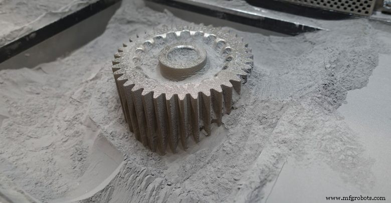
Powder removal
With powder bed processes, a printed part is encapsulated in the unused powder which needs to be removed once the printing process is complete. The excess powder can be removed manually or automatically with the help of specialised equipment, and then recycled for later use.
The removal of any unmelted powder trapped inside a part should also be taken into consideration. For this reason, at least two escape holes should be factored into the design to help easily remove powder after printing.
Part removal
Once a part has been printed, it will need to be removed from the build platform. Build plates are then machined separately to remove excess material and return them to a usable state.
Wire Electrical Discharge Machining (WEDM) is the process of choice for cutting metal parts away from their build plates. WEDM involves creating electrical dischargers, releasing sparks which rapidly cut away material. Although the process is comparatively slow and used only with electrically conductive metals , it leaves a clean, smooth surface.
Cutting parts away with a bandsaw is another, considerably faster method. However, the process lacks the precision of wire EDM. However, if a part is going to be CNC machined afterwards, this precision can be sacrificed in favour of a faster post-processing time.
Support removal
Support structures are often considered a necessary evil when it comes to 3D printing, and this is particularly the case with metals.
Powder bed fusion technologies, like SLM and DMLS, will always require supports to ensure that they are anchored to the base plate and to mitigate the effects caused by residual stresses.
These supports are typically made from the same material as the part itself and help to minimise defects such as warping or cracking resulting from the high processing temperatures.
Supports are typically removed with the help of CNC machining. However, it’s a good practice to design as few supports as possible. In the Designing for Metal 3D printing section, we look at some of the ways to reduce the amount of support structures.
Surface finishing
As we’ve seen, a metal part that has just been printed won’t have the necessary properties required of the finished part. To achieve a smooth finish for a metal part, there are a number of common surface finishing techniques, including machining, sand blasting, media blasting and polishing.
For example, metal polishing can be used to achieve a ‘mirror-like’ finish for your part. Typically, polishing will be required before other surface treatments are conducted, in order to prevent corrosion and improve the appearance of the part. Applications are typically in the aerospace and automotive industries, as well as medical.
Abrasive blasting methods, such as sandblasting, bead blasting and media blasting, involves an abrasive material being forcibly sprayed onto a part to achieve a smooth surface.
Designing for Metal 3D Printing

Key Considerations
Metal additive manufacturing gives us the freedom and flexibility to produce parts with complex shapes and intricate features. However, as with any technology, it does have its own set of capabilities and limitations. Understanding the basics of design for metal 3D printing is therefore crucial to obtain a successful print.
Below are some of the key considerations to keep in mind when designing for metal 3D printing.
1。 Wall Thickness
Choosing the right wall thickness can make the difference between a successful and a failed print.
As a general rule of thumb, it’s recommended to design walls with a minimum wall thickness of 0.4mm.
It’s also important to ensure that the wall thickness of your parts are not too thin or thick, as this can result in deformation during the printing process or cause damage after removal from the build plate.
In the case of thick walls, the mass can be minimised by applying lattice or honeycomb structures, making the overall printing process cheaper and faster.
2。 Support structures
While it’s ideal to design a part with the minimum amount of supports necessary, support structures will virtually always be required with metal 3D printing technologies (except for DED).
Supports play two main roles:first, they are used to anchor a metal part to the base plate to draw away heat, which could otherwise cause residual stresses and build failures.
Second, supports are required to successfully print complex features such as holes, angles and overhangs. For these features, angle measures should be noted:overhangs with an angle less than 45° will require supports.
For features located inside a part, such as horizontal holes along the X or Y axis, it’s generally recommended to design angled support structures.
Angled supports can help maintain a solid connection with the printing bed while minimising the amount of contact the supports have with your part’s surface area. This will make post-processing much easier.
Finally, make sure to check that all support structures will be accessible after printing. Any supports that are difficult to reach will be hard to remove cleanly.
3。 Overhangs and Self-Supporting Angles
Overhangs are unsupported downward-facing surfaces, and will need to be carefully considered when designing a part.
Large overhangs (typically over 1mm) will require support structures to prevent them from collapsing during the printing process. The maximum length of an unsupported horizontal overhang is typically 0.5mm, and it is important to keep your overhangs below this length.
If your design requires overhangs, you can also design fillets and chamfers under the downfacing surfaces to make the overhang self-supporting.
Angled features can be designed self-supporting. For this, the angle of a feature should not be less than 45°.
4. Part Orientation
Part orientation is another critical consideration with metal 3D printing. Experimenting with the orientation of your part is the best way to minimise the amount of support structures needed.
For example, if you want to make a metal part with hollow tubular features, a horizontal orientation will take up more space, while a vertical or angled orientation will save space and reduce the amount of supports needed.
Part orientation is also important in determining the accuracy and surface roughness of a part. When selecting your part orientation, keep in mind that downward and upward facing surfaces will have different surface roughness (so-called down-skins tend to have inferior surface finish). If you want to produce detailed features with the best accuracy, make sure to orientate these on the upward facing surface of the part.
5。 Channels and Holes
Metal additive manufacturing is notable for its ability to produce parts with internal complex channels for improved fluid flow and holes. A general rule of thumb is to not design such features under 0.4mm in powder-bed processes and under 0.2mm in Metal Binder Jetting. Holes and tubes larger than 10mm in diameter will require support structures.
Keep in mind that perfectly round horizontal holes are still a challenge to 3D print. Consider redesigning such shapes into a self-supporting teardrop or diamond shape.
Additionally, if you are designing a hollow part, you need to factor in the design escape holes to ensure the removal of the unmelted powder. A recommended diameter for escape holes is 2-5mm.
Conclusion
Metal 3D printing:a viable manufacturing technology
Metal 3D printing is emerging as a viable manufacturing technology, as advancements across the spectrum of hardware, materials and software continue to be made.
The technology could help to drive new business models and product development strategies by enabling economic low-volume and on-demand production, innovative design possibilities and, of course, mass customisation.
Of course, it will take some time for companies to become fully confident with the technology. However, an increase in knowledge sharing and education will not only help to further the potential of metal 3D printing, but will also spur a wider adoption of the technology across industries.
Discover More Metal 3D Printing Resources:
Expert Interviews
Digital Alloys CEO Duncan McCallum on Joule Printing and the Future of Metal 3D Printing
HP’s Global Head of Metals on the Impact of HP Metal Jet
ANSYS’ Chief Technologist on Achieving Metal 3D Printing Success with Simulation
Sintavia President Doug Hedges on Achieving Serial Production with Metal 3D Printing
APWORKS CEO Joachim Zettler on Finding the Right Business Case for Metal 3D Printing
SmarTech Analysis’ Scott Dunham on the Future of Metal 3D Printing, Service Bureaus and the AM Materials Market [Part Two]
MELD Manufacturing CEO Nanci Hardwick on Fulfilling the Potential of Metal Additive Manufacturing
3DEO’s President Matt Sand on Taking Metal 3D Printing Into High-Volume Production
VELO3D’s VP of Technology Partnerships on Expanding the Capabilities of Metal 3D Printing
Metal 3D Printing Technologies
Metal 3D Printing:Where are We Today?
All You Need to Know About Metal Binder Jetting
Metal 3D Printing:What is Direct Energy Deposition?
An Introduction to Electron Beam Melting
An Introduction to Wire Arc Additive Manufacturing
Your Guide to the Top DMLS Machines [2018]
Designing for Metal 3D Printing
6 Important Design Considerations for Metal 3D Printing
Making Metal Parts Lighter with Metal 3D Printing
Metal 3D printing Materials
Why Materials are the Key to Metal 3D Printing Success:Expert Interview with voestalpine’s Armin Wiedenegger
3D Printing Precious Metals – a New Approach?
Scalmalloy:The Latest High-Performance Material for Metal 3D Printing
A Quick Guide to 3D Printing Metals
A Guide to 3D Printing With Titanium
Metal 3D Printing Challenges
5 Common Problems Faced with Metal 3D printing – and How You Can Fix Them
Quality Assurance for Metal 3D Printing:Solving 3 Common Challenges
Metal 3D Printing Applications
5 Innovative Use Cases for Metal 3D Printing
How Can 3D Printing Benefit Metal Casting? Here Are 3 Ways
3Dプリント