


バインダーフリー電極とそのリチウムイオン電池への応用
要約
エネルギー供給および貯蔵システムとしてのリチウムイオン電池(LIB)は、電子機器、電気自動車、およびユーティリティグリッドで広く使用されています。しかし、LIBのエネルギー密度を高めるための需要が高まっています。そのため、エネルギー密度の高い新しい電極材料の開発が重要になります。多くの新しい材料が発見されていますが、問題は(1)バインダーと活物質(金属酸化物、Si、Li、Sなど)の間の弱い相互作用と界面の問題、(2)大きな体積変化、(3)として残っています。 )低イオン/電子伝導性、および(4)充電および放電プロセス中の活物質の自己凝集。現在、バインダーフリー電極は、上記の問題に対処するための有望な候補として機能します。第一に、結合剤と活物質との界面の問題は、活物質を導電性基板に直接固定することによって解決することができる。第二に、活物質の大容量膨張は、バインダーフリー電極の多孔性によって対応することができます。第三に、イオンおよび電子の導電性は、導電性基板と活物質との間の密接な接触によって向上させることができる。したがって、バインダーフリー電極は一般に優れた電気化学的性能を示します。従来の製造プロセスには、電気化学的に不活性なバインダーと導電性材料が含まれているため、活物質の比容量とエネルギー密度が低下します。バインダーと導電性材料を排除することで、電池のエネルギー密度を大幅に向上させることができます。このレビューでは、バインダーフリー電極の準備、アプリケーション、および展望について説明します。最初に、活物質の担体として機能するさまざまな導電性基板が導入されます。続いて、化学、物理、電気の観点から、バインダーフリーの電極製造法を採用しています。続いて、フレキシブル電池の分野におけるバインダーフリー電極の適用が提示される。最後に、これらの処理方法とアプリケーションに関する見通しを示します。
はじめに
エネルギー危機と環境問題は、再生可能エネルギーと新しい環境に優しいエネルギー貯蔵システムの開発を推進してきました。風力エネルギー、水エネルギー、太陽エネルギーなどの再生可能エネルギー源の断続的な問題のため、バッテリーは重要なエネルギー貯蔵システムであると考えられています[1,2,3]。信頼性が高く効率的なエネルギー貯蔵装置に対する需要が高まっています。リチウムイオン電池(LIB)は、エネルギーと電力密度が高く、セル電圧が高く、動作温度範囲が広く、サイクル寿命が長いため、大きな注目を集めています[4]。今日、電池製造の従来のプロセスでは、ポリフッ化ビニリデン(PVDF)をバインダーとして使用して、コーティング法によって導電剤と活物質を集電体に固定しています[5、6]。より高い容量とより小さなサイズのLIBの需要に伴い、高い比容量を備えた活物質の開発とセル内の不活性物質の削減の両方が重要です。不活性物質を減らす方法は以下の通りです。第一に、従来の結合剤は、導電性結合剤、例えば、ピレンベースのポリマーおよびポリフルオレン共役ポリマーによって置き換えることができる。これらのポリマーは自然に導電性であり、それらの側鎖またはバックボーンは接着力を高めるために修飾されています[7、8、9、10]。導電性バインダーは導電剤として機能します。したがって、セル内の不活性炭素の使用を減らすことができます。ただし、これらのバインダー(PVDFと新しく開発されたバインダーの両方)と活物質(金属酸化物、Si、Sn、Li、Sなど)の間の弱い界面相互作用により、粒子が自己凝集するか、集電体から分離されます。したがって、これらの大容量の新素材は、バッテリー性能の低下を示します[11、12、13、14、15]。次に、カーボンクロス、グラフェン、Niフォームなどの高度な導電性基板が調査され、基板の特殊な接着サイトに活物質を固定することができます。活物質と基板の間の接着は、電極の完全性を大幅に改善する強力な化学的および/または物理的結合によって達成されます。さらに、このプロセスでは、バインダーと導電性炭素添加剤の両方が除去される可能性があります。したがって、エネルギー密度を大幅に向上させることができます[16、17](図1)。
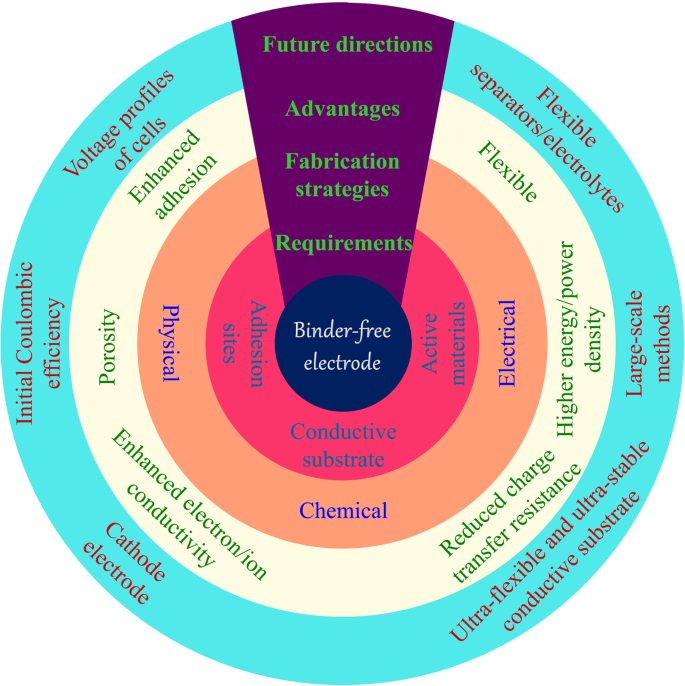
バインダーフリー電極の要件、製造方法、利点、および将来の開発
多くの研究により、バインダーフリー電極の多くの利点が実証されています[18、19、20、21]。対応する電子伝導性基板上に活物質を固定化することにより、活物質表面に有機結合剤が覆われていないため、結合剤と活物質の界面の問題を解決することができます[22、23]。導電性基板に活物質がしっかりと付着し、電子伝導性を大幅に向上させます。多孔質構造などの支持材料の特性は、電解質の浸透とイオンの拡散を促進します[24]。その上、大きな表面積は、活物質の完全な使用とリチウムイオンの輸送に利点があります。さらに、活物質は一般に導電性基板上に均一に固定されており、これによりナノ粒子の凝集を効果的に防止し、繰り返されるサイクリングプロセス中の体積膨張を低減することができます。バインダーフリー電極は一般的に高いLi + を示します そして電子伝導性、まともな電解質の湿潤性と大きな体積膨張空間、そして強い結合強度。したがって、バインダーフリーの電極は、PVDF /活物質/カーボンブラックシステムよりも優れた容量、サイクリング、およびレート性能を示します。具体的には、新しいナノ材料のサイクル寿命が数十サイクルから数百サイクルに延長され、約10 A g -1 の高電流密度が実現しました。 。
活物質の担体としての導電性基板は、バインダーフリー電極の基礎です。導電性マトリックスは、活物質を成長させるのに適した場所を持っている必要があり、その機械的特性は、その用途において決定的な役割を果たします。ウェアラブルでフレキシブルな電子デバイスに電極を適用するには、導電性基板を複数回曲げたり、折りたたんだりできる必要があります。これは、スラリープロセスによって製造された従来の電極では達成するのが困難です。主な理由は、曲げプロセス中に活物質が集電体から分離され、その結果、バッテリーが非アクティブ化されるためです。柔軟なネットワーク上で活物質を直接成長させると、強い相互作用がもたらされ、高いエネルギー密度を維持する堅牢な電極が得られます。これらの柔軟な基板には、主に発泡金属、炭素布、および炭素材料の自立型フィルムが含まれます[25]。
このレビューは、LIB用のバインダーフリー電極の準備、アプリケーション、および展望の概要を提供することを目的としています。私たちの目標は、バインダーフリー電極の最近の開発と改善を強調することです[26]。 LIBの分野で間違いなく重要なドクターブレードの鋳造と浸透の方法は含まれません。まず、主に活物質のキャリアとなるさまざまな導電性基板を紹介します。続いて、化学、物理、電気の観点から、バインダーを使用しない電極の製造方法について説明します。続いて、フレキシブル電池の分野におけるバインダーフリー電極の適用が提示される。最後に、これらの準備方法とその応用に関する重要な問題が予想されます。
導電性基板
導電性基板は、電子伝導性に優れた集電体です。したがって、材料は一般的に金属または炭素材料で構成されています。製造上の制限により、金属集電体は通常、フィルム、メッシュ[27]、およびフォーム[28]に製造されます。金属製品は一般に剛性があり、変形後に簡単に回収することはできません。したがって、これらは、スラリーベースのバッテリーと同じ構成の高エネルギー密度バッテリーにのみ適しています。銅とアルミニウムは、耐酸化性が異なるため、それぞれ負と正の集電体として使用されます[29]。発泡金属には、軽量、大面積、立体構造などの利点があり、バインダーフリー電極によく使用されます[30]。
炭素材料はさまざまな供給源に由来し、その調製において非常に柔軟性があります[31]。これらの材料は、自然界の多種多様な生物学的材料、および化学的に調製されたカーボンナノチューブ、グラフェン、および有機材料からの多孔質炭素構造に由来する可能性があります[17、32]。金属に比べて、炭素材料の種類によっては、軽量で柔軟性に優れているものがあります(柔軟性、折りたたみ性など)。カーボンクロスは、その優れた導電性と柔軟性により、エネルギー貯蔵にますます適用されています[33]。
化学的方法
熱処理
熱処理は、バインダーフリー電極を準備する一般的な方法の1つです。この方法は、加熱および冷却プロセスによって材料の物理的および化学的特性を変更することです。熱処理後、無機塩は対応する金属酸化物に変換され、ポリマーは脱水して炭素伝導性構造を形成します(図2)。バインダーフリー電極の調製では、一般に、活物質を固定化するため、または自立型バックボーンを構築するために熱処理が使用されます。
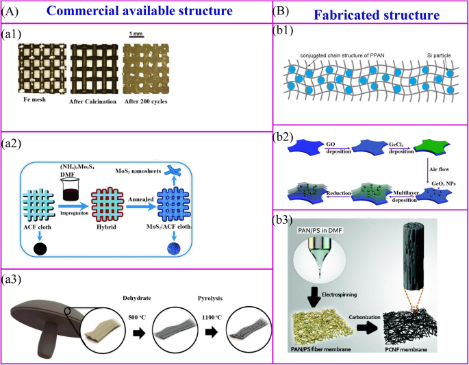
市販の構造物の熱処理( a )および製造された構造( b )。 a1 金属酸化物ナノ粒子は、単純な熱酸化の進行によって金属構造の表面で得ることができます[34]。 a2 活物質は、熱処理によって導電性構造の表面に合成することができます[35]。 a3 バイオマスは炭素化されて炭素構造を実現することができます[32]。 b1 ポリマーと活物質の混合物を炭化して、バインダーフリーの電極を実現することができます[36]。 b2 階層構造は、複数のプロセスによって取得できます[37]。 b3 バインダーフリー電極は、エレクトロスピニング膜を熱処理することで得られます[38]
市販の構造物は、活物質を固定化するための支持骨格として利用されています。これらの材料は、金属メッシュ、炭素繊維、市販のスポンジ、生物学的誘導体、市販のスポンジ[39]などで構成されています(図2a)。金属酸化物ナノ粒子は、単純な熱酸化の進行によって金属集電体の表面で合成できます[34](図2a1)。さらに処理することなく、これらの集電体をバインダーフリーLIBのサポート材料として直接使用できます。鉄メッシュでサポートされたFe 2 O 3 は、1050 mAh g -1 という非常に高い放電容量を示しています。 200サイクル後。活物質の前駆体溶液による導電性膜の熱処理は、バインダーフリー電極を製造するために広く開発された方法です(図2a2)。代表的な例は、極薄のMoS 2 活性炭繊維(ACF)布の表面にコーティングされたナノシートは、(NH 4 ) 2 MoS 4 溶液に続いてアニーリング。電気化学的性能は、971 mAh g -1 の放電容量が実証されています。 100 mA g -1 の電流密度で達成されます [35]。バイオマス材料の熱処理は、バインダーフリー電極を調製するための簡単な方法です。 Ozkanらは、ポートベローマッシュルームをバインダーフリーのLIBアノードとして炭化しました(図2a3)[32]。高温では、バイオマス材料の構造を維持でき、自然に存在するヘテロ原子と金属イオンが炭素材料にドープされるため、電子伝導性や容量などの電気化学的性能が向上します。
ポリマーは、バインダーフリー電極の自立骨格を構築するための主要な材料であり、骨格構造は、ポリマーとその調製方法によって決定されます(図2b)[40]。まず、一般的なポリマーの場合、550°Cでのポリマー活性材料複合フィルムの熱分解により、バインダーフリーの電極を作成できます(図2b1)[36]。 Si / SiO x / PAN複合電極はこの方法で作成されます[41、42]。アニーリング後、ポリアクリロニトリル(PAN)をNドープ導電性構造に変換できます。カーボンネットワークは、SEIを安定させ、体積変化に対応するだけでなく、電極に優れた柔軟性と機械的強度を提供します。同様に、Si / rGO電極は、Si、還元型酸化グラフェン(rGO)、およびポリビニルピロリドン(PVP)懸濁液をニッケルフォームにキャストした後、アニーリングプロセスを行うことで得られます[43]。第二に、レイヤーバイレイヤー(LBL)プロセスは、複雑な構造やナノ材料を作るための魅力的な方法です。多層の電極は、Ti箔をポリ(ジアリルジメチルアンモニウムクロリド)(PDDA)溶液、酸化グラフェン(GO)懸濁液、PDDA溶液、およびH 3 水溶液に浸すことによって製造できます。 PMo 12 O 40 特定のサイクルで、その後500°Cで熱処理を行います[44]。このようなLBL法は、バインダーフリー電極を大規模に調製するために適用することができる。この種の方法は、メソポーラスアナターゼTiO 2 の作成に適しています。 /ニッケルフォーム[45]、MoS 2 ナノシート/ ACF、および多層GeO 2 / rGO(図2b2)[37、46]。最後に、バインダーフリーの電極は、活物質をポリマーにカプセル化してから、新しいナノ構造に製造することで製造できます(図2b3)。柔軟な階層型ナノファイバーマットは、エレクトロスピニングとそれに続く熱処理によって合成できます。
市販されて製造された構造には多くのメリットがあります。活物質は市販の構造物の表面にコーティングされ、製造された構造物は活物質をカプセル化するための容器として機能します。活物質のカプセル化とは対照的に、表面コーティングは活物質と電解質のより多くの接触を作ります。したがって、レートパフォーマンスは向上しますが、初期クーロン効率が低下し、サイクリングパフォーマンスが低下します。
熱水処理
水熱法は、過去数十年の間にさまざまな分野で広く使用されています。現在、この技術は、メカニズムの解釈と材料の製造に関して多大な努力を払ってきました。水熱プロセスでは、金属イオンが溶液に溶解し、その後、高温高圧で過飽和溶液を形成します。このプロセスの間、結晶成長は基板の核形成点で起こります。熱処理によって調製された凝集粒子と比較して、水熱法は、穏やかな条件下で、高純度で、均一で、単分散で、制御可能なナノスケール材料を生成することができます。微細なナノ構造の熱水プロセスは、エネルギー貯蔵材料で広く注目されています。
水熱法を使用してバインダーフリー電極を調製するための全体的な合成プロセスは、図3aで説明した手順と同様です。補助材料が最初に入手されます。支持材料が滑らかで核形成点が限られている場合、それらの表面への活物質の堆積は禁止されます。一般的に、カーボンクロスは親水性を高めるために酸性または熱処理が必要です。さらに、適切な沈殿剤を添加して溶液のpHを調整し、基板の表面での前駆体の成長を促進する必要があります。得られた材料を熱処理して、ナノ構造を維持しながら所望の複合材料を得る。 Hu、Zhang、および同僚は、Zn x を準備するためのスケーラブルな方法を報告しました Co 3-x O 4 ナノキューブ/ CNF(カーボンナノファイバー、CNF)。立方体のサイズは、水熱プロセスで適用されるpHによって調整できます[47]。
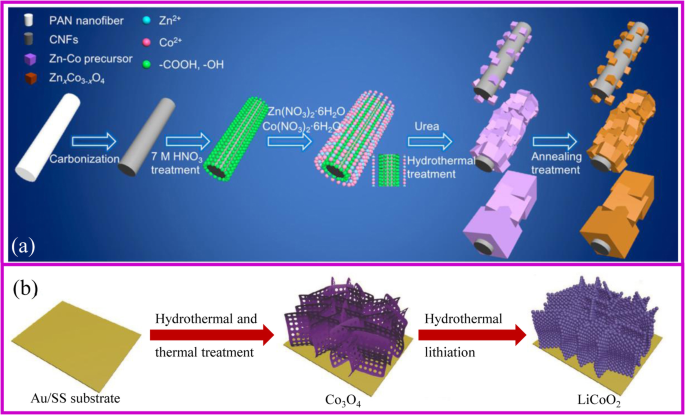
a ZnCoO x のスキーム / CNF複合材料の製造[47]。 b 水熱法を用いた陰極電極の製造[48]
水熱法は、単一および複数の成分を製造することができます[49]。 TiO 2 など、バインダーフリー電極の多くの形態が開発されています。 カーボンナノチューブ(CNT)足場上のナノロッド[50]、Fe 3 O 4 ナノ粒子、NiOナノコーン、Ni(OH) 2 ナノシートとFe 3 O 4 Niフォーム上に成長した/ Ni / Cナノプレート[51,52,53,54]、MnO 2 グラフェンフォーム上のナノフレーク[55]、およびFeF 3 ・0.33H 2 O炭素繊維上の花のような配列[56]。 Liと同僚はNiCo 2 を成長させました S 4 NiCo 2 が存在する独自の3D構造を示すナノチューブアレイ S 4 ナノチューブは、長さが5 nm、幅が100nmを示します[57]。多孔質NiCo 2 O 4 3Dグラフェンネットワーク上で成長したナノニードルは、NiCl 2 を使用して取得できます。 ・6H 2 OとCoCl 2 ・6H 2 前駆体としてのO [58]。これらのナノ構造は、導電性基板上に均一に分布しています。したがって、これらの複合材料は、電子移動を促進し、放電/充電プロセス中の活物質の体積変化に対応するだけでなく、LIBの高容量、高レート機能、およびサイクル安定性を備えた電気化学的特性を改善します。具体的には、Fe 3 O 4 nanoparticle @ Niフォームは、543 mAh g -1 の可逆容量を示しました。 2000サイクル以上後の電流密度10℃で[51]。 NiOアレイ@Niフォームは969mAh g -1 の容量を提供できます 0.5 Cの電流密度で、約605.9 mAh g -1 のままです。 10°Cで[52]。
水熱法は、カソード材料の金属酸化物のリチウム化を達成するための優れた戦略であることは注目に値します。従来のリチウム化では、前駆体とLi塩を均一に混合する必要がありますが、これは、目的のバインダーフリー電極を得るのが非常に困難です。水熱リチウム化は、前駆体の処理を必要としない解決方法であるため、バインダーフリーのカソード電極を製造するための魅力的な方法の1つです。 2018年、Xia etal。多孔質LiCoO 2 を準備しました Co 3 の熱水リチウム化による基板としてAuコーティングされたステンレス鋼を備えたバインダーフリーのカソード O 4 前駆体(図3b)[48]。この電極は、104.6 mA h g -1 の容量で優れたレートおよびサイクリング性能を示します。 10°Cの速度で、1000サイクル後の容量保持率は81.8%です。
ケミカルバスデポジション
化学浴堆積(CBD)は、化学反応によって基板上に活物質をその場で成長させるプロセスです。水熱合成法と比較して、この合成法はスケールアップが容易であり、特別な装置を使用せずにナノ材料を低温および周囲圧力で成長させることができます。さらに、CBDと水熱法は同様のメカニズムで基板の表面に材料を成長させるため、基板の要件は非常に似ています。図4aに示した手順と同じように、活物質の前駆体は、反応のpHと温度を調整することによって核形成して成長します。たとえば、3Dグラフェン/ MnO 2 ハイブリッドは、酸性KMnO 4 に3Dグラフェンエアロゲルが存在することによって調製されます。 ソリューション[59]。
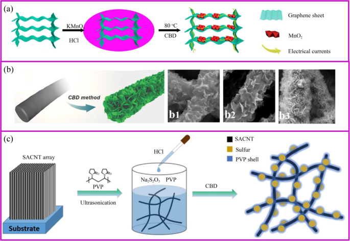
a 3Dグラフェン/ MnO 2 の調製の概略図 ハイブリッド、および3Dグラフェン/ MnO 2 での電子移動の図 ハイブリッド[59]。 b CNF @ Ni(OH) 2 の製造のためのCBD法 [60]。 b1–3 Ni(NO 3 の濃度の増加に伴うさまざまなハイブリッド膜 ) 2 解決。 c PVP @ S-SACNTコンポジットの合成手順の概略図[61]
活物質の形態は、支持物質、反応時間、および前駆体濃度の影響を受けます(図4b)。基質が最初の核形成部位を決定します。たとえば、MnO 2 の形態 は、グラフェンとCNTの基板上のナノシートとナノ粒子です[62、63]。さらに、支持材料上の活物質の形態は、前駆体濃度によって影響を受ける。たとえば、薄いNi(OH) 2 ナノシートは、低Ni(NO 3 )でナノファイバーの表面に垂直に形成および成長し始めます ) 2 濃度(図4b)[60]。ただし、Ni塩濃度の増加に伴い、Ni(OH) 2 の厚い層が発生します。 ナノシートは徐々に形成されますが、これはNi(OH) 2 の迅速で均一な核形成に起因する可能性があります。 。したがって、支持材料上の活物質の形態は、粒子[64]、シース、ナノシート[65]、およびナノワイヤー[66、67]など、さまざまである可能性があります。水熱法で作成された電極と同様に、ナノスケールの材料を使用した多孔質で導電性のアーキテクチャは、リチウムイオンの迅速な拡散と高速のリチウム化/脱離のための電子の効率的な輸送のための連続チャネルを提供できます。
非常に有望な陰極材料である硫黄は、穏やかな条件下でCBDによって合成することができます。硫黄材料は、Na 2 間の単純な反応に基づいています S 2 O 3 室温で水溶液中の酸。プロセスはシンプルで環境に優しいです。適切なテンプレートまたは界面活性剤を適用すると、特殊なナノ硫黄構造を得ることができます[68]。導電性材料がS 2 を吸収できる場合 O 3 2- 、中間相で大量の硫黄が生成されます。フェニルスルホン化官能基で修飾されたグラフェンは、その場でのレドックス反応を介して硫黄を均一に堆積させることができます[69]。バインダーフリーのPVPカプセル化硫黄電極は、硫黄ナノ粒子を導電性ネットワークにその場で固定化することによって調製されます(図4c)。 PVPは、疎水性のアルキル鎖と親水性のアミド基を持つ両親媒性ポリマーであり、分散剤として使用できます。溶液に酸を加えた後に硫黄が形成され始めると、PVPの疎水性により、硫黄がS表面に優先的にコーティングされ、多硫化物の溶解を保護するための緻密な層が形成されます[61]。
化学蒸着
化学蒸着(CVD)は、高温の基板の表面にガス状の物質が堆積する化学反応です。この方法は、触媒の助けを借りて、三次元構造とナノワイヤ上に均一な膜を生成することができます。 CVDプロセスは、(1)高温基板の表面での反応ガスの拡散と吸収、(2)活性部位でのガスの反応によるコーティング材料の形成、(3)排気発生ガス。温度、圧力、ガス比、種類を制御することで、目的のコーティング材を得ることができます。
CVD法は活物質を直接成長させることができます。 CVDプロセスに対応する印象的な例がTayと同僚によって報告されました[70]。 3Dニッケルフォーム/ CNT複合材料は、ニッケルフォームを基板として、エタノールを前駆体と炭素源の両方として合成されます。得られたCNTは、NiOナノシート成長の堆積のための基板として機能する。アモルファスFeVO 4 ナノシートアレイは、VCl 3 を使用して柔軟なステンレス鋼基板上で直接成長させることができます。 前駆体として。 601 mAh g -1 の可逆容量を提供できます および453mAh g -1 それぞれ8Cと15Cの高電流密度で[71]。
CVDによって作成された表面層は、電極と電解質の間の保護インターフェースとしても機能します。ヤンらは、CVDプロセスを通じて活物質をコーティングするための炭素前駆体としてエチレンを使用しました。これにより、構造の安定性が向上するだけでなく、優れた電子伝導ネットワークが形成されます。カーボンコーティング層を備えたSiナノワイヤは、良好なレート性能を示します[72、73]。 2016年、Cui etal。は、CVD法によって調製された親油性材料の薄層を備えた多孔質材料が、Liイオンの均一な堆積を促進する足場として機能できることを示しました[74]。この材料は、3 mA / cm 2 の大電流密度でも、小さな過電圧で安定したサイクリング性能を示します。 充電および放電プロセス中。
CVD法は、高度なSi材料を製造するための主要な戦略の1つです。シリコンは、4200 mAh g -1 という最高の比容量により、次世代LIBにとって最も有望なアノード材料です。 動作電圧が低い[75]。ただし、シリコンは大きな体積変化に悩まされており、固体電解質界面(SEI)の連続的な形成、粉砕、およびサイクリングプロセス中の容量低下につながります[76]。一般に、高度なシリコン材料は、シリコン粒子の後処理または二酸化ケイ素の還元によって調製することができます。 CVDは、高純度のシランまたはシラン代替物を還元または熱分解することにより、薄膜またはナノワイヤシリコンを調製するための望ましい方法です。 2008年、Cui etal。 CVD法を使用して、触媒としてAuナノ粒子を使用してステンレス鋼上にシリコンナノワイヤー(Si NW)を合成し、LIBのアノードとして適用することに成功しました[77]。直径約89nmのシリコンナノワイヤーは、割れることなく400%の体積変化に対応できます。さらに、ナノワイヤは集電体上で直接成長し、すべてのナノワイヤが容量に積極的に貢献します。ナノ構造により、多孔質電極全体の比表面積が非常に大きく、イオン伝導性に優れています。ナノワイヤシリコン材料は、ほぼ4200 mAh g -1 の理論容量を達成できます。 C / 20レートで初めて。ナノワイヤの直径は、サイクリングプロセス後に89nmから141nmに増加しましたが、全体的な構造は損なわれていませんでした。 Siの成長は触媒によって制御されます。ステンレス鋼は、Si膜形成の触媒としても機能します。ただし、集電体上にSi層が形成されると、Si層と集電体の間に大きな応力が発生する可能性があります。 Siの成長は、アクティブなシードを制御することにより、特定のステップで妨害される可能性があります。たとえば、AuまたはSnナノ粒子を含む化学的に安定したグラフェンまたは金属Ge表面は、Si NW成長のシードとして機能します[78、79]。
原子層堆積
原子層堆積(ALD)法は、気相、自己制限、および層ごとの堆積であり、CVDと同様です。この方法は、原子の層ごとの堆積でナノスケールで制御可能な薄膜を生成することができます。したがって、プロセスは、互いに反応する可能性のある少なくとも2つの異なる前駆体ガスで構成する必要があります[80]。 ALDプロセス中に、最初のガスがパイプ炉に導入され、基板と反応して、活性基を含むコーティング層を形成します。最初のガスが完全に放出された後、2番目のガスが導入されて最初の層と反応します(図5a)[81]。このプロセスを繰り返すことにより、異なるコーティング層を実現することができます。 ALDによるコーティング膜は、主に基板、ガス前駆体、温度などの影響を受けます。従来の薄膜堆積法と比較して、ALDは化学反応によって基板全体のコーティング厚を正確に制御でき、コーティング層はピンホールだけではありません。 -複雑な3D構造に堆積した場合でも、自由で密度が高く、均一ですが、コンフォーマルでもあります。 ALDのこれらの機能は、ナノテクノロジーと材料に最適な選択肢です。
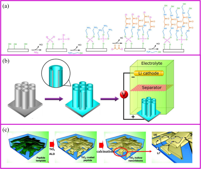
a ALD技術メカニズム[81]、および b の2つの例 表面コーティング[82]および c 活物質の製造[83]
ALDで調製された電極は、一般に優れた電気化学的特性を備えています。 TiO 2 最も研究されている電極材料です(図5b、c)[84]。最近、SnO 2 [85]、MoS 2 [86]などが準備され、LIBの活物質として首尾よく使用されています(図5c)[87、88]。 ALDは気相合成法であるため、材料の表面または細孔内に制御可能な厚さの均一な層をコーティングできます。 Kangと共同研究者[83]は、電極の活物質としてのナノリボンにより、電解質を材料の内部に浸すことができ、それによってリチウムイオンの拡散速度が大幅に向上することを実証しました。テンプレートの助けを借りて、ナノリボンの中空空間は、幅がほぼ100〜200 nm、高さが20〜50nmのトンネルサイズのALDによって合成できます。電解液が中空空間を簡単に濡らすことができます。 TiO 2 のレートパフォーマンス ナノスケールネットワークは、100 nm-TiO 2 のネットワークと比較して、5Cで少なくとも5倍に増加しています。 ナノパウダー。 Biener etal。 TiO 2 でコーティングされた多孔質電極 レイヤー。コーティング層が薄い材料ほど、レート性能が優れていることがわかります。 TiO 2 の場合 layer thickness increased from 2 to 7 and 20 nm, the capacity decreases from 227 to 214 and 157 mAh g −1 , respectively [89].
The most general application of ALD in electrochemical storage is to protect the surface stability of electrodes to enhance the electrochemical performance [90]. The uniform Al2 O 3 coating on TiO2 nanotubes for LIBs is the most representative example of surface protection (Fig. 5a) [82]. The coating thickness of the Al2 O 3 layer onto the TiO2 nanotube can be controlled by ALD from 0.2, 1 to 10 nm according to the repeated cycles. The 1 nm coating Al2 O 3 layer can suppress the SEI formation and undesirable side reactions, which greatly improves the capacity. In addition, Al2 O 3 as an artificial layer can participate in the formation of SEI with Li–Al–O groups, which are great ionic conductor. Therefore, the Li-ion conductivity in improved and great rate performance can be achieved. Noked et al. demonstrated the 14 nm Al2 O 3 layer can effectively improve the stability of lithium metal interface by avoiding the reactions with electrolyte, cathode shuttles, etc. [91]. Comparing with the bare lithium metal anode, the ALD-protected anode can significantly improve cycling performance.
Electrical Methods
Electroplating
Electroplating is a versatile technique that functions to improve the surface properties of materials or to prepare nanoscale structures. The deposition mechanism is that in the case of an applied electric field, the ions move to the positive electrode and are reduced on the surface of the substrate to form a film. The thickness of film is controlled by the current density and time. Through post-treatment, the metal film can be oxidized to the corresponding metal oxide.
Template synthesis is the most popular method for preparing nanostructures of various materials using electroplating in LIBs. Chen, Xia, and coworkers obtained porous CoO semisphere arrays using the polystyrene as the template [92]. Yan, Tong, and coworkers demonstrated that CoO can coat on the surface of ZnO nanorod arrays by electroplating method. The ZnO template can be removed by treating the obtained electrode at KOH solution [93].
Electroplated surface layers also serves as a protective interfaces between the electrode and the electrolyte. Cu/TiO2 NT/Ti electrode can be prepared via electroplating Cu on TiO2 NT/Ti film. The prepared materials display a much higher discharge capacity, cycle stability, and Li + diffusion coefficient than bare TiO2 NT/Ti electrode [94]. Mulder et al. designed a 3D Ni honeycomb current collector for stable Li metal anode [95]. By controlling the porosity of Ni material with polyethylene glycol as an additive, the Li plating/stripping performance can prolong to 300 and 200 cycles at 0.5 mAh cm −2 and 1.0 mAh cm −2 , respectively, at 1.0 mA cm −2 。
Anodization
Anodization is a well-established technique for modifying a layer on the metal surface. Generally, the metal surface can be thermal treated to form the corresponding oxide protective layer. However, this heating process often carries out at a high temperature, which changes the material structure and properties. Therefore, it is necessary to develop a low temperature method. Anodization refers to a technique in which a metal material is oxidized and precipitated in the electrolyte solution by applying an anode current at room temperature. Anodization is popular because of its controllable structure, economical, and large-area preparation.
Li etal。 firstly reported the porous Fe3 O 4 thin film as anode material cycled about 100 cycles at the 0.1 C [96]. Subsequently, TiO2 [97], NiO [98], WO3 [99], CuCl nanoparticles [100], etc. were prepared and showed decent cyclic stability, good ion and electron conductivity, and enhanced capacity. The NiO@Ni foam can deliver a reversible capacity up to 705.5 mAh g −1 and 548.1 mAh g −1 at a current density of 1 A g −1 and 2 A g −1 それぞれ。
Electrophoretic Deposition
Electrophoretic deposition (EPD) has been widely used as a surface coating and film preparation method. The deposition mechanism is that during the process, the charged particles with small sizes (need to disperse into the solution) in a suitable suspension migrate towards an electrode under an applied electric field (Fig. 6a, b). The morphology of the achieved film is significantly influenced by the electrolyte solution [104]. EPD has the advantages of low cost, simplicity, green, and controllable operation [105].

a Schematic of process for fabrication of binder-free, carbon-free film electrodes [101]. b Schematic fabrication process for the Fe3 O 4 /CNTs/rGO composite electrode [102]. c Schematic illustration of the synthesis route for rGO/active materials/Ni foam [103]
An electrode made by EPD shows better electrochemical performances than slurry-coated electrode. Robinson and coworkers proved that the Co3 O 4 nanoparticle films formed by EPD showed better adhesion and cycle performance than the electrode prepared by conventional methods (Fig. 6a). The EPD can provide a more effective mixed state between active materials and conductive additives [101]. It is worth noting that carbon nanotubes, graphene, and other carbon materials together with active materials can be deposited onto the current collector, which significantly improves the electron conductivity [106, 107]. Besides, the porous structure formed during the EPD process is crucial to accommodate the volume change during lithium-ion insertion and extraction. Zhao and coworkers demonstrated that the Si nanoparticle electrode prepared through EPD shows better electrochemical performance (Fig. 6b) [102, 108].
EPD is able to deposit surface layers composed of either active or inert materials. These layers serve as protective interfaces between the electrode and the electrolyte. For example, the reduced graphene oxide thin film deposited onto the surface of the electrode to improve the electrical conductivity and to buffer the volume changes during charge/discharge processes (Fig. 6c) [103].
Physical Methods
Electrospinning
Electrospinning is a simple and popular technique to synthesize 1D nanostructures with fiber diameters ranged from tens of nanometers up to micrometers [109]. This preparation is difficult to achieve by the approaches mentioned above. This technique can produce polymers, organic, and inorganic composites with dense, hollow, or porous structures [110], from polymer solutions based on electrostatic forces [111]. An electrospinning unit generally consists of a syringe and a needle, a grounded collector, and a high-voltage supply, as shown in Fig. 7a, b [117]. During the electrospinning process, polymer solutions are loaded in the syringe and move into the needle to form a droplet. When a high voltage is applied between the needle and the collector, the electrostatic force at the surface of droplet would drive it to elongate to form a fiber. Finally, the solid polymer fibers would deposit onto the collector.

The schemes of a single axial and b coaxial electrospinning [111, 112]. c Inorganic fibers [113]. d Inorganic particles encapsulated carbon fibers [114]. e The modification of carbon fibers [115]. f Carbon fiber membrane with nanoparticles [38]. g Highly flexible carbon fiber membrane [116]
The polymer solutions and needle are the key points for the success of fiber fabrication. Polymer solution should reach the minimum viscosity for the formation of homogeneous fiber structure. The solvent of polymer should have a lower evaporation rate, which allows the polymer solidification after leaving the needle. The needle should be designed with coaxial structure to achieve hollow or core-shell fiber structure (Fig. 7b). For the coaxial electrospinning, the core and shell solutions should be adjusted to be immiscible or non-precipitable. Besides, during the electrospinning process, solution flow rates, voltage, temperature, distance from needle to the collector, and diameter of the needle have a huge influence on the fiber structure.
The obtained electrospun membrane needs further treatment to be a binder-free electrode. Carbon, ceramic, or metal nanofibers can be synthesized from the carbonization of electrospun fibers that contain polymer, metal salts, or metal atoms, respectively. Their composites such as metal/C and ceramic/C can be also obtained from their corresponding mixed precursors followed by a one-step or multi-step heat treatment. A wide range of electrospun materials have been investigated for LIBs including metal oxides (e.g., TiO2 、Fe 2 O 3 , ZnO, NiO, CuO, LiCoO3 , Li4 Ti 5 O 12 , and LiMn2 O 4 ) [118, 119], hybrids [120] (e.g., SnOx /C, SiOx /C, Co3 O 4 /C, SnOx /C, TiO2 /C) [113, 121,122,123,124,125,126,127,128,129,130], and polymers (e.g., polyvinyl alcohol (PVA), PAN and PVP, poly(vinylidene fluoride-co-hexafluoropropylene) (PVDF-HFP), and polyethylene oxide (PEO)) [131].
Conventional electrospinning generally disperses metal salts and nanoparticles inside the fibers. However, the nanoparticles can adhere to the outside of the fibers as well (Fig. 7c). Lan, Yang, and coworker prepared 3D free-standing spider-web-like membranes with high mass loading of bismuth (Bi) nanoparticle clusters followed by carbonization in nitrogen gas [132]. The 3D Bi/C membrane provides good mechanical properties and stabilizes the Bi nanoparticles up to 200 cycles.
The architecture of fibers can be optimized to accommodate large volume changes and instability of the electrode materials during cycling process. The adjustment of the fiber structure can be started from either inside or outside of the fiber. The internal fiber can be regulated by the polymer solution and post-treatment, while the external fiber structure is controlled by post-treatment. When the polymer solution contains etchable materials, a porous fiber structure can be prepared after carbonization and template etching (Fig. 7d). This porous materials is capable of accommodating higher sulfur and suppressing the polysulfides shuttle effects [114]. The polymer can individually form an active material at the expense of flexibility self-standing property. This disadvantage can be addressed by additives. Liu etal。 showed the PAN fibers with an appropriate amount of CNTs can still be self-standing after sulfurization [115]. The sulfur only exists in the form of Li2 S 2 およびLi 2 S 3 rather than polysulfides in the sulfurized PAN. Therefore, it shows ultra-stable cycling performance up to 1000 cycles (Fig. 7e).
Alternatively, the post-treatment of the surface of electrospun fibers is another way to prepare the high-performance binder-free electrode (Fig. 7f) 。 After carbonization, the three-dimensional conductive network is formed to provide good electronic conductivity. The fiber surface also provides a large number of sites for the growth of active materials with easy access to electrolyte [38]. Another post-treatment is to coat the nanofibers with a protective surface layer. Generally, the nanoparticles spinning out with the polymer solution is inevitably exposed at the surface of the fiber. This part of the material may fall off from fibers during the cycling process, so the surface coating is equivalent to the protection of the fiber [133].
In addition to polymer solution, the needle is also of importance to the fibers design. The core-shell composite nanofiber can be prepared by a dual nozzle coaxial electrospinning setup (Fig. 7g) [116]. This needle can achieve a great core-shell fiber structure. Besides, hollow fibers can be prepared by designing the inner and outer solutions. When the hollow fiber is filled with the active material, there is sufficient space to allow the volume to expand [112].
Vacuum Filtration
The vacuum filtration method is a rapid manufacturing process to assemble different kinds of nanoscale materials into the macroscopic film for various applications. This process is low-cost, rapid, and efficient, which demonstrates a promising strategy for various functional films. 2D materials can be easily assembled into flexible self-standing paper-like materials, which can be directly used as flexible binder-free electrodes in energy storage devices [134, 135]. In general, the active materials are randomly dispersed between the supporting materials. Therefore, high mechanical strength and flexibility are preserved for the papers (Fig. 8) [136, 137].

The scheme of vacuum filtration process [136]
The vacuum filtration features as the following strengths. Firstly, active materials can adhere on the conductive substrate, leading to the improvement of electron conductivity. For example, the electron conductivity of MoS2 can be largely improved; therefore, better rate performance can be obtained [138, 139]. Secondly, the large surface area is in favor of the contact between active materials and lithium ions, which facilitates the transportation of Li-ion. When the active material is added into the 2D material, the interlayer spacing becomes large; thus, the electrolyte can be immersed. The lithium ions are more accessible to the material; thereby, the interface impedance of material is reduced [140]. Thirdly, the effective material utilization is also facilitated by hindering the aggregation of 2D materials [141,142,143]. Lastly, the material agglomerations and electrode instabilities result from the huge volume change of active materials during Li insertion/extraction [144, 145]. Supporting sheets can absorb stress induced by volume expansion, similar to the role of elastic buffer [146, 147].
Different types of nanostructures can be assembled into 2D materials. For example, the nanoparticles, nanotubes, nanosheets, nanorods, etc. can fabricate into the graphene sheets [148]. When CNTs as additive are assembled into the nanosheets, the restacking of the nanosheets can be prevented, and the conductivity of ion and electron can be greatly increased [149]. The electrode chemical properties can be enhanced by coating or mixing active materials on other conductive materials and then assembling into 3D functional materials [150,151,152]. It is mainly attributed to the synergistic effects that 3D structure not only serves as a flexible scaffold for strains/stresses release and volume expansion, but also offers a three-dimensional conductive architecture with open channels for electron transfer and Li-ion diffusion. Besides, pre-protection of active materials is a way to improve material stability. The surface modified anode materials in graphene exhibit high capacities, long cycle-life, and excellent rate performance [153]. The Mn2 P2 O 7 -carbon in graphene electrode delivers a capacity of 585 mA h g −1 at a current density of 1000 mA g −1 。 When increasing the current density to 5000 mA g −1 , a high capacity of 400 mA h g −1 can be remained even after 2000 cycles [153].
Physical Vapor Deposition
At certain temperature and airflow rate, the elemental vapor can be easily deposited onto the porous supporting materials [154,155,156]. Solid sulfur and red P nanoparticles are the typical materials, which can be deposited into porous carbon materials. The commercialization of sulfur as cathode materials is blocked by several intrinsic problems, including low electronic/ionic conductivity, large volumetric expansion, and shuttle effect of intermediate polysulfides (Li2 S x (4 ≤ x ≤ 8)). Particularly, the shuttle effect of polysulfides results in transport of sulfur from cathode to anode and the reaction with Li metal, which leads to significant capacity loss and safety issues. So far, the design of porous structure is the basic strategy to suppress the polysulfides shuttle effect, and sulfur vapor deposition is an effective way for the fabrication of S/C composite. It is an environmentally friendly, solvent-free method in which the sulfur powder undergoes a physical deposition process with no changes of chemical properties [157]. With proper absorbent in the structure, the shuttle effect of polysulfides can also be fixed. Recently, Yang, Zhang, and coworkers reported Ti3 C 2 Tx paper is a good host for sulfur deposition (Fig. 9a). This Ti3 C 2 Tx paper shows no cracks after 25 convexly and concavely bending cycles (Fig. 9b, c) [158]. Yu and coworkers [159] demonstrated porous carbon fibers encapsulated with red P shows high capacity of 2030 mAh g −1 at 0.1 C rate after 100 cycles. It is worth noting that physical vapor deposition (PVD) is only one of the procedures of immobilizing S or P onto carbon materials. Therefore, the most important research direction is how to design a porous conductive matrix.

a The scheme of fabrication of robust, freestanding, and conductive Ti3 C 2 Tx /S paper. Photographs of freestanding Ti3 C 2 Tx /S paper when bending b convexly and c concavely, showing good mechanical flexibility similar to that of the pure Ti3 C 2 Tx paper [158]
Application in Flexible Batteries
Flexible devices, such as wearable displays, sensors, sportswear, mobile communication devices, rollup displays, and so on, are one of the important directions for intelligent and smart world [160]. The development of these new devices requires the power of a flexible battery system [161,162,163]. However, current advanced pouch and 18,650 cells cannot be used on flexible devices due to the rigid material properties. Each component of the flexible battery, such as electrodes, separator, and solid electrolyte, must be flexible (Fig. 10a) [164]. The conventional electrode is generally adhered to the metal foil by a coating method to physically bond the active material and the conductive agent. During repeated bending and folding, the active material separates from the current collector, ending up with deactivation. For example, the Li4 Ti 5 O 12 (LTO)-based electrode folded about 100 cycles would present the detachment of LTO from Al foil. The impedance of the electrode increases from the first fold, and the higher the active material loading, the faster the impedance increases (Fig. 10b). At the same time, the pouch cell bending 30° results in serious capacity fade (Fig. 10c).

a Assembly and bending tests of flexible batteries with flexible electrodes [164]. b Electrical resistance change with folding cycles [165]. c Capacity retention of folded cells at different angles at 1 C [165]
There are many strategies to fabricate flexible electrodes. Song etal。 reported that coating LTO particles and Ag nano wires onto the polyethylene terephthalate (PET) web can greatly improve the electrode flexibility and stability. The electrical resistance of Ag@LTO@PET electrode does not change during 1000 folding cycles (Fig. 10b). Pouch-type Ag@LTO@PET-based half cells showed great cycling performance with little capacity decay when the electrode was bent at any angle (Fig. 11c) [165]. The most mature method is to fix the active material on a flexible substrate. As described in the “Introduction” section, the direct growth of the active material on the conductive substrate can improve battery energy density and rate performance. Herein, we take the carbon cloth and carbon materials as the example to show the application of binder-free electrodes in flexible devices.

a Schematic illustration for the structural features of the flexible SnO2 nanosheets on flexible carbon cloth electrode during the folding (I), the rolling (II), and twisting (III) tests. b Current-time curves of the composite samples at various bending angles of the 1st and 200th cycles, and the inset images show the corresponding bending angles for measurement and photographs [166]
Most carbon materials cannot be used in flexible electronics. For example, a binder-free electrode based on graphite paper can only maintain 25 cycles in a bent state [167]. Comparing with other carbon materials, carbon cloth with excellent flexibility and electrical conductivity is one of the most promising materials for the flexible battery application. Even after the surface modification of inorganic materials, carbon cloth still shows excellent flexibility. As shown in Fig. 11a, there are no apparent changes of the electrode after bending, rolling, twisting, folding, and crumpling tests. After the mechanical test, the active materials on the carbon cloth can maintain structural integrity. Also, after 200 bending cycles, the current value slightly decreases from 17.3 to 16.8 mA, which demonstrates great stability (Fig. 11b) [166].
It is particularly difficult to synthesize flexible carbon materials. For example, the PAN film becomes much more brittle and fracture after carbonization, which is difficult to use in flexible batteries. The ideal carbon material, like the clothes we wear, bending and folding many times can still remain intact. The flexibility of the material can be greatly improved through reasonable design such as the addition of functional additives.王ら。 reported that the carbonized PAN film with SiO2 filler can fully recover to its original state after repeated rolling or folding process [114]. When assembled into the pouch cell, it can withstand at different bending angles up to 180°. Yu etal。 demonstrated that Zn(CH3 COO) 2 assists the uniform carbonization of PAN, which relieved the stress concentration [130]. The film obtained by this method can return to the initial state after folding four times (Fig. 12a). When assembled into the pouch cell, it can light the LED at any folding angle. When the pouch cell is disassembled, the binder-free electrode remains intact while the slurry-based electrode is completely destroyed (Fig. 12b–e).

a Digital photographs of Zn(CH3 COO) 2 -PAN film, which can be folded four times. LED lighting tests of a full battery when b flat, c folded once, and d folded twice;および e digital photographs of the electrode after the LED lighting test [130]
結論
In conclusion, recent research progress on the preparation of binder-free electrodes for LIBs has been summarized. The fabrication methods focus on the chemical, physical, and electrical treatment, such as thermal treatment, hydrothermal treatment, CBD, ALD, CVD; vacuum filtration, electrospinning; and electrophoretic deposition, anodization, electrodeposition. Thermal treatment is the most commonly used chemical method to carbonize polymer for free-standing structure or decompose of the precursor of metallic oxide. The hydrothermal and CBD methods are very attractive due to accurate control of the size and morphology of nanomaterials. CBD and hydrothermal methods present in situ growth of active materials on the substrate through a chemical reaction. CVD is defined as the deposition of a gas carrier on a heated surface by a chemical reaction, while the ALD technique is a vapor phase chemical deposition process that is capable of producing high-quality nanoscale thin films in an atomic layer-by-layer manner. The vacuum filtration and electrospinning are the representative physical methods. The former is a physical manufacturing process to assemble different materials like nanoplatelets and nanoparticles into the macroscopic film. The latter can produce 1D nanoscale materials with fiber diameters ranged from tens of nanometers up to micrometers. The electrical method is a widely used technique to make coatings and thin films. However, it is not often used to prepare binder-free electrode. Among these methods, CVD and CBD are excellent ways to prepare silicon-based and sulfur-based materials, respectively.
The binder-free electrode shows better electrochemical performances than the traditional slurry system. The binder-free electrode can improve ionic and electronic transportation, cycling performance, and energy density of the electrodes. In addition, nanoscale materials are uniformly anchored on the supporting materials, which can effectively prevent the agglomeration of nanoparticles and mitigate the volumetric expansion during the repeated cycling process.
The conductive matrix plays a crucial role in the electrochemical properties and performances of the binder-free electrode. The ultra-flexible film has great potential to make a big breakthrough in the field of wearable and flexible devices. However, existing substrates are still unable to meet the requirements. The flexible device requires the binder-free electrode to bend and fold for numerous times with no damage and no separation from the substrate. According to current research process, ultra-flexible and ultra-stable carbon materials become the most promising candidate for next-generation flexible binder-free electrode.
Despite the difficulties, the future is expected. The uniform and large-scale growth of the active material on the conductive substrate is one of the necessary conditions for practical application. Fortunately, it is now possible to achieve. Practical applications need to consider the basic properties of the electrode in the battery, such as the initial Coulombic efficiency and voltage profiles. Therefore, the active materials for both anodes and cathodes should be carefully selected. For example, Si, Sn, or carbon materials serve as promising candidates for anode materials while the cathode materials may be selected from S matching with Li metal, or the existing Li metal oxides. In addition, flexible batteries can be achieved with all of flexible components, such as electrodes, separators, and electrolytes. Although these aspects have been studied for a long time, breakthrough is needed to facilitate the research progress.
データと資料の可用性
すべてのデータは制限なしで完全に利用可能です。
略語
- LIB:
-
リチウムイオン電池
- PVDF:
-
ポリフッ化ビニリデン
- ACF:
-
Active carbon fiber
- PAN:
-
ポリアクリロニトリル
- rGO:
-
還元型酸化グラフェン
- PVP:
-
ポリビニルピロリドン
- LBL:
-
Layer-by-layer
- GO:
-
酸化グラフェン
- PDDA:
-
Poly (diallyldimethylammonium chloride)
- CNT:
-
カーボンナノチューブ
- CBD:
-
化学浴堆積
- CVD:
-
化学蒸着
- SEI:
-
固体電解質界面
- Si NWs:
-
シリコンナノワイヤー
- ALD:
-
原子層堆積
- EPD:
-
Electrophoretic deposition
- PVA:
-
ポリビニルアルコール
- PVDF-HFP:
-
Poly(vinylidene fluoride-co-hexafluoropropylene)
- PEO:
-
Polyethylene oxide
- Bi:
-
Bismuth
- PVD:
-
Physical vapor deposition
- LTO:
-
Li 4 Ti 5 O 12
- PET:
-
ポリエチレンテレフタレート
ナノマテリアル
- エネルギー材料へのチタンの応用
- 13種類の耐火材料とその用途
- 材料:自動車用ガラスおよび炭素繊維強化PP
- 再吸収抑制タイプII /タイプIZnSe / CdS / ZnSコア/シェル量子ドットの合成と免疫吸着アッセイへのそれらの応用
- リチウムイオン電池用の高性能アノード材料としてMWNTに固定されたSiO2 @ Cナノ粒子の容易な合成
- リチウムイオン電池用のCr3 +およびF-複合ドーピングを用いたLiNi0.5Mn1.5O4カソード材料の合成と電気化学的性質
- PPy被覆MnO2ハイブリッドマイクロ材料の調製とリチウムイオン電池のアノードとしてのそれらの改善されたサイクル性能
- スーパーキャパシター用途の電極としてのグラフェン/ WO3およびグラフェン/ CeOx構造の評価
- PCB材料と高電圧用の設計
- 各種エネルギーとその例
- 用途に合わせた抵抗溶接電極