


人間の頭からロボットの頭へ
コンポーネントと消耗品
>  |
| × | 1 | |||
| × | 3 | ||||
 |
| × | 1 | |||
| × | 1 |
必要なツールとマシン
>  |
|
アプリとオンラインサービス
|
このプロジェクトについて
何か新しいことをすることを計画しますが、それほど費用はかかりません。私はロボット工学がとても好きです。でもサーボなどの部品が必要なので作りたくないです。今私は4つのサーボモーターを持っていますわずか13ドルです。すでにLinkit1ボードとArduinoボードを持っています。
だから、すべての軸で私たちの頭のように動くが安価なロボットの頭を作ることを計画してください。 さまざまなセンサーと方法を研究しますが、最終的にはすべてのアイテムを手にした方法を見つけます。このプロジェクトで勉強することはたくさんあります。さあ、私が勉強していることを説明します。 私が学んだことを太字で示します。
スマートモバイルチルトセンサーを使用して頭を制御します
ステップ1:必要な材料 <図>
 <図>
<図> 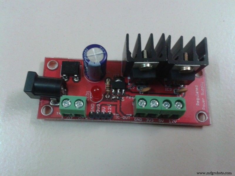 <図>
<図> 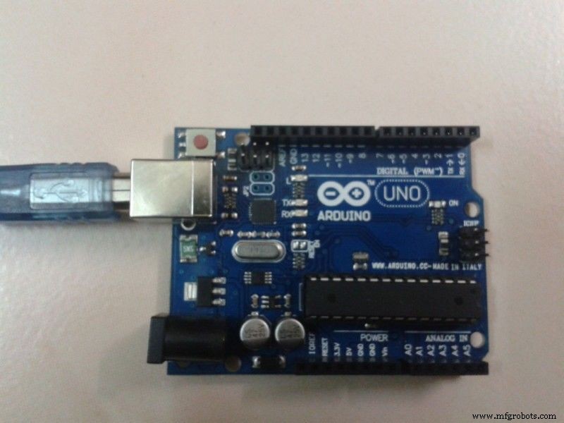 <図>
<図> 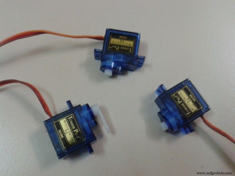 <図>
<図> 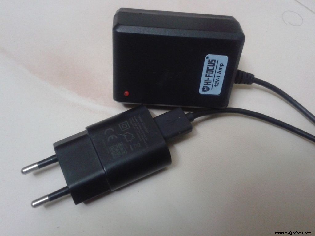 <図>
<図> 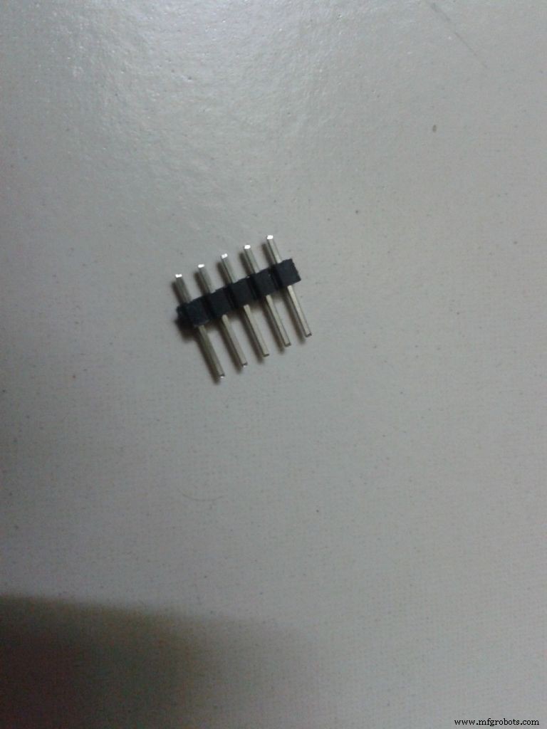 <図>
<図> 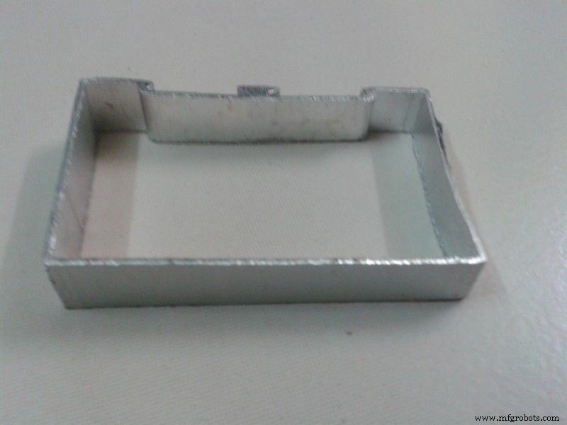
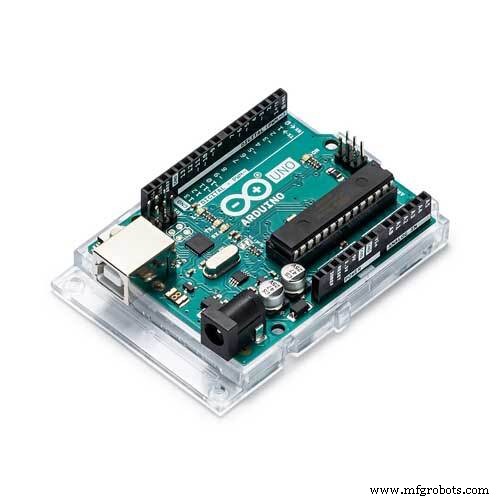
使用した材料
1)Arduinouno。
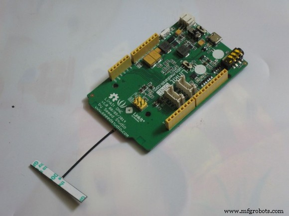
2)1つのボードをリンクします。
3)3つのサーボモーター。
4)SensoDuinoの無料Androidアプリはこちらからダウンロードしてください。
5)安定化電源ボード(12V、5V、3.3V)。
6)プレーンPCB。
7)PCBオスコネクタ
8)廃アルミニウム供給カットピース。
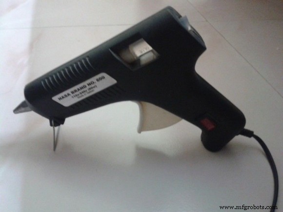
9)ホットグルーガン。
10)12Vおよび5Vアダプター。
11)飾るアイテムがいくつかあります。
Linkit1ボードとArduinounoを選ぶ理由
UにLinkit1ボードと3Vサーボモーターがある場合、5Vサーボは正常に機能しないため、ArduinoUNOは必要ありません 1つのボードをリンクします。
UにArduinounoとBlueトゥースモジュールがある場合は、は必要ありません。 1つのボードをリンクします。
ブルートゥースシールドがないので、Linkit1ボードとArduinounoを使用します。
ステップ2:サーボシールドを所有する <図>
 <図>
<図> 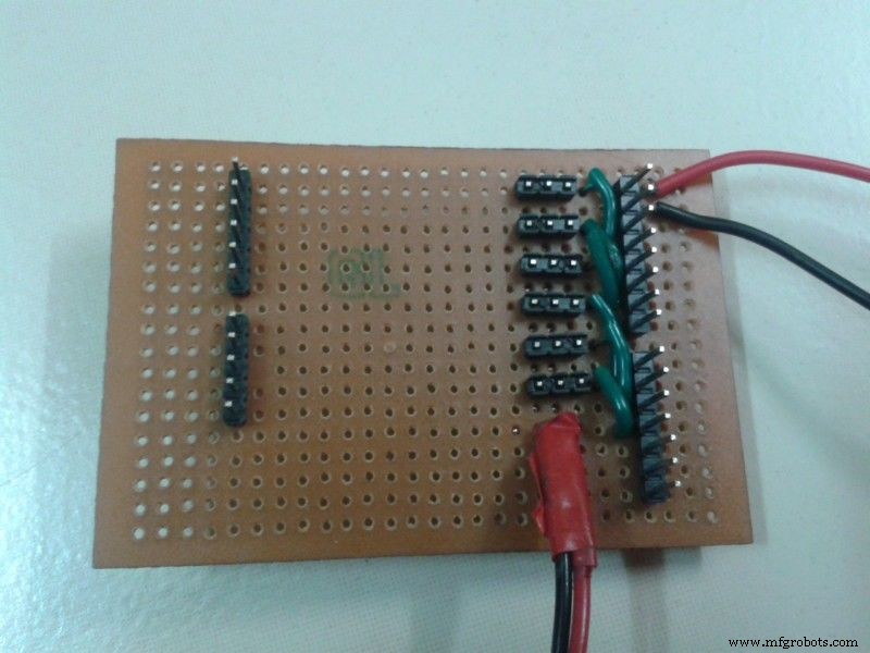 <図>
<図> 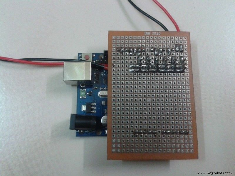
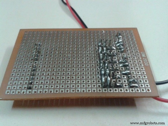
1)Arduino用のサーボモーターシールドを作成します(3vサーボを使用する場合でも注意してください。Linkit1にはPWMピンが2つしかない)
2)サーボモーター用にPCBのようなシールドを作ります。
3)このボードを使用して、arduinoピン(3、5、6、9、10、11)から6つのサーボモーターを制御できます。
4)ここでは3線式サーボを使用しています。ここで、電源は外部の5Vレギュレータ電源ボードから供給されます。
5)制御サーボはArduinoボード用のアダプター供給を使用します。 PCのUSB電源は振動の原因になります。これにより、サーボモーターが過熱し、損傷します サーボモーター 。 (私のサーボダメージの1つ)
ステップ3:Linkitを1つの接続にする <図>
1)Linkitは、サーボを制御するためにarduinoと話したいです。
2)そのためには、Linkitの1つのボードのTxをArduinoボードのRxに接続し、両方のGndを接続します。
3)受信したデータは、Arduinoに送信されます。
注:-
Arduino Bluetoothシールドを使用している場合は、1つのボードを使用してセットアップ全体を制御します。
ステップ4:サーボ位置 <図>
 <図>
<図> 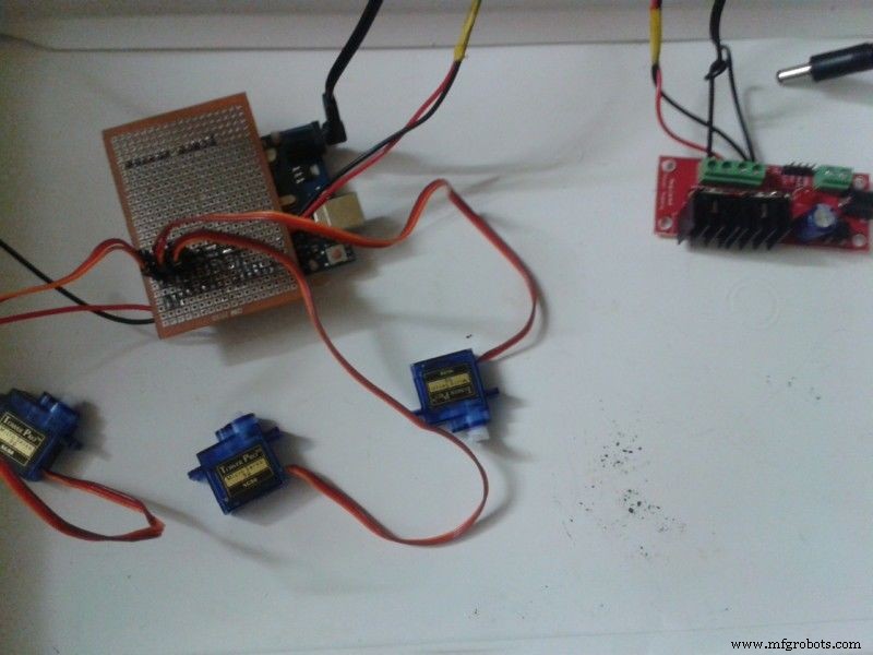
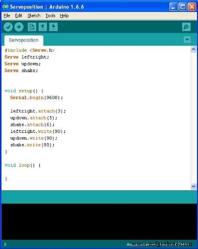
1)すべてのサーボモーターを90度に設定します。そのためには、上記のプログラムをarduinoにアップロードしてください。
2)サーボ電源とarduino電源を5Vピンと12Vピンでレギュレータ電源ボードに接続します。
3)Arduinoデジタルピン3、5、6で作成したPCBの場合は、サーボメスコネクタをオスコネクタに接続します。
3)12Vアダプターをレギュレーターの電源ボードに接続します。
4)アダプターのスイッチを入れます。
5)これで、すべてのモーターがプログラムに従って90度回転します。
次に、ローターを乱さずにモーターを切り離して結合します。
位置ArduinoIDEコードはServoposition.inoとして提供されます
ステップ5:計画 <図>
 <図>
<図> 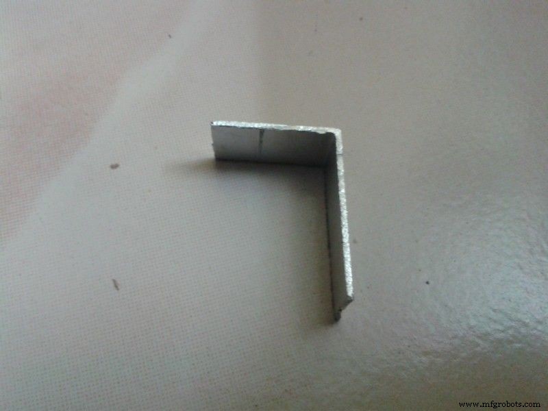 <図>
<図> 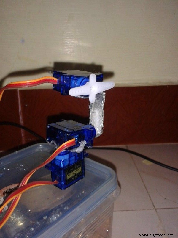
1)頭を3軸x、y、zで回転させます。
2)ローテーションは
a)ヨー-左右を参照してください。
b)ピッチ-上下を見る
c)横方向にロールシェイクします。
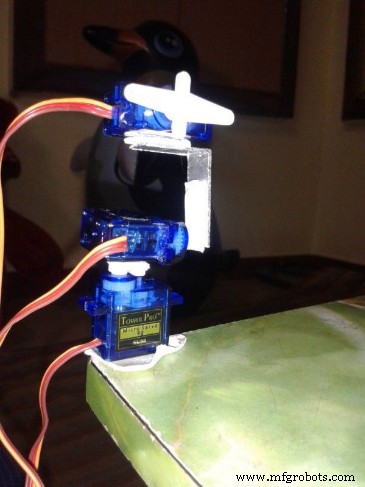
3)最初に両面テープを使用してサーボを計画します。
4)アルミ製の仕切り片をL字型にカットし、上部のサーボを2番目のサーボに固定します。
5)計画に従って、または写真に示すように、サーボモーターホーンを接続します
6)90度の場合、すべてのサーボの中心は真っ直ぐでなければなりません。
7)両面テープを使用してすべてのサーボとアルミニウムLピースを貼り付け、他のサーボを妨害しない動きを確認します。
ステップ6:構築 <図>
 <図>
<図> 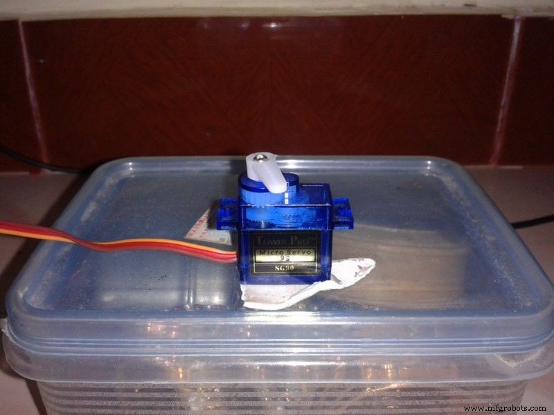 <図>
<図> 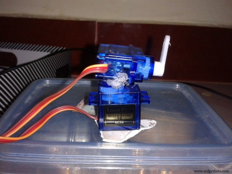 <図>
<図> 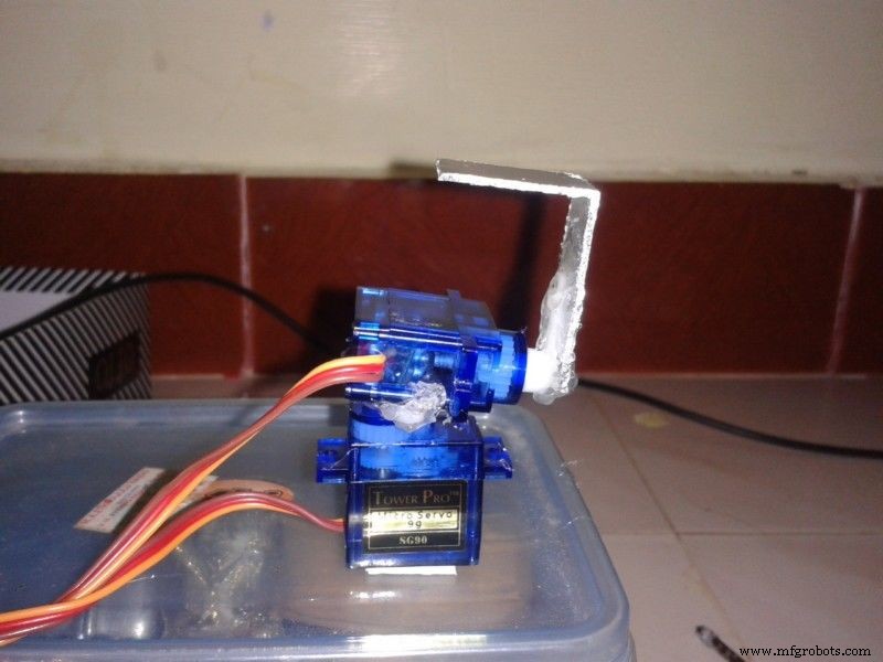 <図>
<図> 1)それを恒久的に修正する時が来ました。
2)両面ステッカーを1枚ずつ取り外し、ホットグルーガンを使用して恒久的に固定します。
3)サーボを損傷しないように注意してください。
4)再度サーボコネクタをarduinoボードに接続し、電源をオンにします
5)最後の画像のようにすべてのスタンドをまっすぐに適合させます。
ステップ7:Androidアプリの詳細 <図>
 <図>
<図> 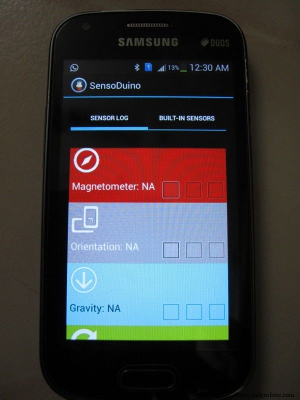 <図>
<図> 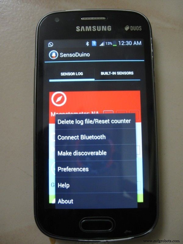 <図>
<図>  <図>
<図> 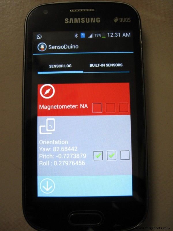 <図>
<図> 1)Android携帯でSensoDuinoを開きます。すべてのモバイルセンサーの読み取り値を表示し、Bluetooth経由で送信できるオプションがあります。
2)すべての最新のセンサーが一覧表示され、電話で使用できるセンサーのみを選択できます。
3)メニューに移動し、[Bluetoothの接続]を選択します。
4)リストには利用可能なBluetoothデバイスが表示されます。
5)Linkit1つのBluetoothを選択します。
6)私たちのプロジェクトでは、方向センサーを使用します。最初のボックスをオンにし、2番目のボックスをオンにしてBluetooth経由でデータを送信します。
7)メニューのパフォーマンスオプションを選択して、各センサーのパフォーマンスも設定します。各読み取りの時間間隔を変更します。
ステップ8:コーディング
1)Linkit1用に2つのコーディングがあります。
ブルートゥースを使用して、モバイルからデータを取得し、シリアルポートを使用してArduinoに送信します
2)Arduinoポグロム
シリアルポートでデータを受信すると、文字を文字列として連結します。そして、indexofとsubstringを使用して、1つのフルセットの結果を分割します。そのセットで、indexofとsubstringを使用して各位置を取得します。それから、arduinoのマップを使用してサーボを0度から180度に制御します。 Bluetoothシールドを使用している場合は、requiremnetに従ってプログラムを変更してください。
プログラムの仕組み
1)方向センサーを使用して、ロボットは私たちのように頭を回転させます。
a)ヨーは、磁気位置に応じて0〜360度の回転です。そのために、90〜270度を使用します。ここで、180はサーボの90度です。ですから、キャップをかぶるときは紐として180度向きにしたいのです。
b)ピッチは表側が上下になっています。センサーの読み取り値は-180〜 + 180です。-90〜 +90を使用します。
c)ロールは横に振られます。0から90から0から-90から0です。-90から90を使用します。
Linkit1コードはLinkitonehead.inoで提供されています
ArduinoコードはArduinohead.inoに記載されています
ステップ9:ボードを注文する
<図>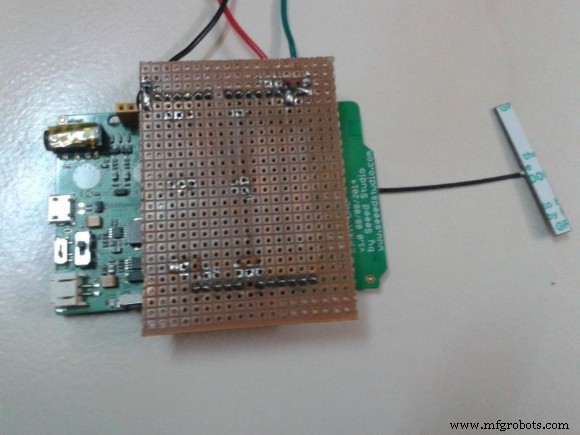 <図>
<図>  <図>
<図> 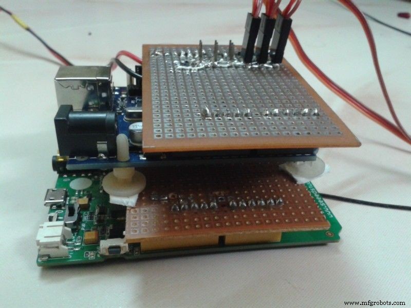
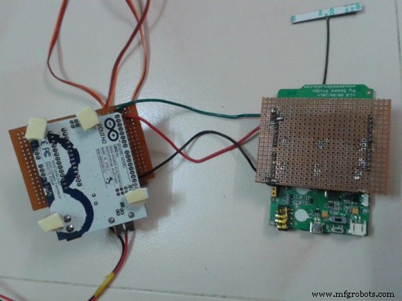
1)両方のシールドボードを両方のマイクロコントローラーの上部に接続します。
2)両面ステッカーを重ねて貼り付けます。
3)端末を撃たないように注意してください。
ステップ10:手でトレイルする
次に、すべての電源をオンにして、携帯電話を手元で使用します。ヨーに180度向きを向けて座り、モバイルを使用して3つのサーボモーターすべてを制御します。
ステップ11:顔を修正する <図>
 <図>
<図> 
1)そのx-masの時間は、店でたくさんのサンタクロース人形を見つけました。
2)人形を1つ購入し、ダブルサイドタップを使用して上部サーボアームにヘッドを固定します。
ステップ12:コントロールハットを準備する <図>
 <図>
<図>  <図>
<図>  <図>
<図>  <図>
<図>  <図>
<図> 
1)普通の帽子をかぶってください。
2)図のようにキャップの前面に両面ステッカーを貼り付けます。
3)携帯電話を両面テープに貼り付けます。
ステップ13:ビデオのテスト
低パフォーマンスのテスト は、250ミリ秒ごとのセンサーのリフレッシュレートを意味します。
ステップ14:最終的なビデオ
100ミリ秒あたり1回の読み取りというセンサー読み取り速度でのアクションを確認してください
コード
- Servoposition.ino
- Linkitonehead.ino
- Arduinohead.ino
Servoposition.ino Arduino
#includeServo leftright; Servo updown; Servo shake; void setup(){Serial.begin(9600); leftright.attach(3); updown.attach(5); shake.attach(6); leftright.write(90); updown.write(90); shake.write(90); } void loop(){}
Linkitonehead.ino Arduino
#include#include int readval; String inputString =""; String outputString =""; int firstpoint =0; int secondpoint =0; void setup(){if(! LBTServer.begin((uint8_t *) "Sivam_LIO")){return; } // Serial.begin(9600); Serial1.begin(9600); } void loop(){uint8_t buf [64]; int bytesRead; if(LBTServer.connected()){while(true){bytesRead =LBTServer.readBytes(buf、32); if(!bytesRead)break; inputString =""; for(int j =0; j <32; j ++){char inChar =char(buf [j]); // inputStringに追加します:inputString + =inChar; } // Serial.println(inputString); Serial1.println(inputString); // firstpoint =inputString.indexOf( '>'); // Serial.println(inputString); // Serial.println(firstpoint); // if(firstpoint> 0)// {/ / secondpoint =inputString.indexOf( '>'、firstpoint + 1); // if(secondpoint> 0)// {// outputString =inputString.substring(firstpoint、secondpoint); // inputString =inputString.substring(secondpoint); // Serial.println(outputString); //} //}} delay(100); } else {LBTServer.accept(5); }}
Arduinohead.ino Arduino
#includeServo leftright; Servo updown; Servo shake; String inputString =""; boolean stringComplete =false; String teststr2; String Sensorid; String Sensorrecid; String Sensorval1; String Sensorval2; String Sensorval3; int S1; int S2; int S3; int startchr =0; int endchr =0; int rot1; int rot2; int rot3; void setup(){Serial.begin(9600); // inputString.reserve(200); leftright.attach(3); updown.attach(5); shake.attach(6);} void loop(){} void serialEvent(){while(Serial.available()){char inChar =(char)Serial.read(); if(inChar!='\ n'){inputString + =inChar; }} startchr =inputString.indexOf( '>'); if(startchr> =0){endchr =inputString.indexOf( '>'、startchr + 1); if(endchr> 0){teststr2 =inputString.substring(startchr、endchr); inputString =inputString.substring(endchr); startchr =teststr2.indexOf( '、'); Sensorid =teststr2.substring(1、startchr); endchr =teststr2.indexOf( '、'、startchr + 1); Sensorrecid =teststr2.substring(startchr + 1、endchr); startchr =endchr; endchr =teststr2.indexOf( '、'、startchr + 1); Sensorval1 =teststr2.substring(startchr + 1、endchr); startchr =endchr; endchr =teststr2.indexOf( '、'、startchr + 1); Sensorval2 =teststr2.substring(startchr + 1、endchr); startchr =endchr; Sensorval3 =teststr2.substring(startchr + 1); S1 =Sensorval1.toInt(); S2 =Sensorval2.toInt(); S3 =Sensorval3.toInt(); rot1 =map(S1、90、270、180、0); if(rot1 <0)rot1 =0; else if(rot1> 180)rot1 =180; rot2 =map(S2、-90、90、0、180); if(rot2 <0)rot2 =0; else if(rot2> 180)rot2 =180; rot3 =map(S3、90、-90、0、180); if(rot3 <0)rot3 =0; else if(rot3> 180)rot3 =180; if(rot1!=0&rot1!=180){leftright.write(rot1); } if(rot1!=0&rot1!=180){updown.write(rot2); } if(rot1!=0&rot1!=180){shake.write(rot3); } delay(15); // Serial.print( "Sensor-"); // Serial.println(sensorid); // Serial.print( "Sensor Val1-"); // Serial.println(rot1); // Serial.print( "センサーVal2- "); // Serial.println(rot2); // Serial.print( "Sensor Val3-"); // Serial.println(rot3); }}}
製造プロセス