


高炉製鉄の進化
高炉製鉄の進化
鉄の最初の製錬の起源は、記録されていない人類の文明の歴史に隠されています。古代に使用されていた鉄の道具の最初の証拠は、実際には、ピラミッドの2つの石の間の接合部で鉄の道具が見つかったエジプトから来ています。多くの先史時代の鉄の道具の起源はおそらく隕石でした。流星の鉄には5%から26%のニッケル(Ni)が含まれていますが、製錬された鉄には微量のNiしか含まれていないため、流星から作られた鉄のアーティファクトは製錬された鉄の物体と区別できます。
4,000年以上前、人々は隕石を発見しました。しかし、採掘された鉄鉱石からの鉄の生産が始まるまでには、さらに2、000年かかりました。インドで最初に発見された製錬鉄は、西暦前1800年(西暦前)にさかのぼります。鉄の製錬は、紀元前1500年頃に、ヒッタイト帝国の主題であるアルメニアのカリュベの間で行われたと言われています。彼らの帝国が紀元前1200年頃に崩壊したとき、さまざまな部族が彼らと一緒に製鉄の知識を取り入れ、それをヨーロッパとアジアに広めました。ヨーロッパと西アジアのすべてにおける製鉄の知識は、最終的にはこの情報源にまでさかのぼります。鉄器時代は、鉄の製錬の発見から始まりました。
製錬の始まり
硫化銅鉱石の還元と同様に、酸化鉄の最初の還元はおそらく偶然でした。これらの古代の冶金学者(当時の鉱夫、化学者、技術者)は、酸化鉱石の直接炭素(C)還元によって鉄を単純な炉で製造できることに気づいたのは、観察の力でした。製錬プロセスの最初の記録された描写は、紀元前1500年頃のエジプトの墓の壁で発見されました。 (図1)このプロセスは、鉱石と未知の燃料を使用した単純なピットであり、足で操作するベローズを使用して火を強めました。次の3000年間、鉄の製造技術は、酸化物のC還元によって製造された鉄スポンジと、スポンジを叩いて製造された鉄製品で大きな変化はありませんでした。
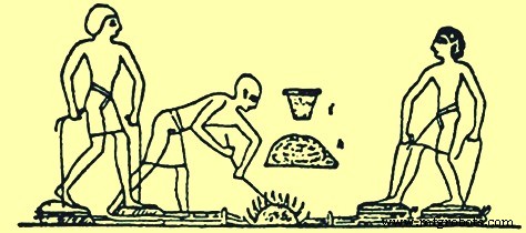
図1エジプトの墓に描かれた鉄の製錬プロセス
酸化鉄鉱石は地球の多くの地域に存在します。したがって、エジプトで鉄鉱石の還元が行われていたのとほぼ同時に、他の地域でも行われていました。インド、中国、アフリカ、マラヤは、この製鉄慣行の初期開発の拠点として機能しました。これらの国で開発された炉がすべて非常に類似していたことはおそらく重要です。形状とサイズに違いがありましたが、炉は機能的に同一でした。 。鉄への化学的還元は溶けずに起こり、得られた金属は比較的純粋で柔らかく、鍛造鉄と呼ばれていました。有用な形に打ち込むことができました。槍、矢先、短剣、その他の道具や武器はこれから製造できました。鍛造鉄。
約2000年の間、最初の千年紀(西暦)の終わり頃まで、鉄は「塊鉄炉」プロセスによって小さな地元の炉床で生産されていました。これらの構造物のサイズは考古学的調査では入手できませんが、塊鉄炉の最新の再建では、内径が300mmでした。 x高さ1000mm。塊鉄炉のプロセスでは、炉床が建設され、その中に、マウンドが生成されるまで、木炭と鉄鉱石の多層が配置されました。このマウンドの周りには、粘土とレンガのケーシングが建てられ、上部に排気ガス用の穴があり、下部にベローズの操作によって生成される空気の吹き付け用の穴があります。その後、木炭に火がつけられ、木炭がなくなるまでベローズが作動しました。その後、ケーシングが壊れて開き、プロセスがうまく進んだ場合は、海綿状の鉄の山とスラグの水たまりがありました。熱い海綿状の鉄をハンマーで叩いて鉄ビレットまたは鉄製品を製造した。ここでは、塊鉄炉プロセスでの製錬中に発生する反応について説明します。木炭の火は一酸化炭素(CO)を生成し、熱はボグ鉱石から水を追い出し、ヘマタイトを生成しました。 COは、ヘマタイトを酸化第一鉄、ウスタイトに還元しました。次に、COはウスタイトを元素鉄に還元します。反応は完全には進みませんでした。それは平衡位置に進んだので、結果として生じるガスはCOと二酸化炭素(CO2)の混合物でした。ただし、ウスタイトは砂と反応して、生成されるスラグの主成分である鉄かんらん石(ファヤライト)を生成する可能性もあります。このファヤライトは、炉の条件下では元素鉄に還元できなかったため、製錬プロセスに関する限り行き止まりでした。製造された鉄の融点は約1%でした。スラグの融点は約1,100℃であったのに対し、1,540℃でした。到達した温度は、スラグを溶かすのに十分な高さでしたが、鉄を溶かすのに十分な高さではありませんでした。このプロセスは十分に機能しましたが、残りのスラグにはまだ多くの鉄が含まれており、多くの場合、最大60%以上のFeO(酸化鉄)が含まれていました。スラグは2種類あり、一部はボグ鉱石ドロスの開いた多孔質であり、一部は赤鉄鉱石から得られたように、コンパクトで硬く、非常に注入しにくいものでした。
製鉄プロセスの開発
この最初の製鉄プロセスの改善は、製錬所の穴を石と泥で覆い、木と革で作られたベローズを使用することによって行われました(図2)。中国では、鉄の使用は紀元前600年頃に現れ、紀元前403年から紀元前222年の間に広く広がりました。中国人は優れた製鉄技術を開発し、鋳鉄器具の発見に基づいて、早くも紀元前200年に溶鉄が製造されました。中国とインドの両方の古代の書物は、鉄の製錬に言及しています。その他のアーティファクトには、剣、斧、鎌、くわなどがあります。 CE 310までに、インドのデリーとダールの有名な鉄柱の建設を可能にするのに十分な量の鉄を生産することができました。デリーの錬鉄柱は、高さ18 m、直径410 mm、重さ17トンです。日本では、「タタラ」として知られる伝統的な製鉄プロセスは、17世紀まで完全には開発されていませんでした。北アメリカ、南アメリカ、オーストラリアでは、鉄の製錬は古代の住民には知られていませんでした。製鉄技術はヨーロッパ人によってこれらの国にもたらされました。
地中海周辺で開発された製鉄プロセスは、ヨーロッパを北上して広がっていました。フェニキア人、ケルト人、ローマ人は製鉄技術の普及に貢献しました。ローマ人がイギリスまで北に広めた製鉄技術の1つは、初期のボウルまたはシャフト炉でした。この炉は、丘の側面に組み込まれた高さ2mの椀型の容器または円筒形のシャフトで構成されていました。炉内の火を扇動するために使用される空気は、卓越風に面したボウルの底の近くに建てられた開口部によって提供されました。炉は上部の開口部から木炭と鉄鉱石の層で満たされ、下部の開口部から点火されました。
製錬がどのように行われたかについては2つの理論があります。1つはプロセスを加熱する空気を提供する下部開口部から風が吹き込み、もう1つは風が開放上部を吹き飛ばして前壁の内側に低圧領域を作成するというものです。下部の開口部から空気を吸い込みました(図2)。どちらの場合も、プロセスは風に依存しており、年間を通じて信頼性がありませんでした。製品は再びスポンジ鉄の塊であり、下部の開口部から取り出され、ハンマーで叩いて最終的な形になりました。
初期の製錬所のもう1つのタイプは、蜂の巣炉でした(図2)。この炉は、木炭と鉄鉱石を交互に積み重ねることにより、平らな地面に建設されました。マウンドは厚い粘土の層で覆われ、ベローズに接続されたブローパイプが下側の側壁から挿入されました。木炭の下層に点火し、ベローズから加圧空気を供給しました。このバッチタイプのワカサギの終わりに、粘土のドームは崩壊しました。製造されたスポンジ鉄は、破壊された蜂の巣炉からハンマーで掘り出されました。これらの炉での生産は小さな鉄の塊であり、製錬炉は各生産実行後に解体して再構築する必要がありました。
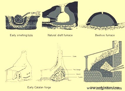
図2製鉄の初期プロセス
これらのタイプの製鉄プロセスは、現代に至るまで数百年にわたってあまり改善されることなく使用されていました。その後、およそ8世紀の間に、スペイン北東部のカタルーニャの山々で操業している小さな鍛冶場は、製鉄における初期の重要な冶金学的進歩の1つを表しています。初期のカタロニアの鍛造品(図2)には、炉床と呼ばれる石造りのカップがあり、高さ約910 mm、直径760mmでした。ベースの正面から少し離れたところに小さな開口部があり、羽口と呼ばれるノズルを取り付けることができました。羽口ノズルは、空気を供給するためにベローズに接続されていました。炉床は木炭の塊で羽口の高さまで満たされていました。次に、鉄鉱石を羽口の上に置き、鉱石の上にさらに木炭を重ねました。木炭に火がつけられ、ベローズからの空気が熱いCOを鉱石に押し付け、鉄鉱石を熱くてゴツゴツした鉄の塊に減らしました。ブルームと呼ばれる鉄の塊は、最大160 kgの重さがあり、石の構造を破壊することなく、トングで鍛造の炉床から取り除くことができました。この量の鉄は5時間で生成できましたが、以前の技術では5時間で約23kgしか生成できませんでした。カタロニアの鍛造品は、次の200年間でサイズが大きくなり、その使用はフランス、ベルギー、イギリス、ドイツに広がりました。炉床のサイズは1m四方に拡大し、長方形の石のブロックで作られました。 「トロンプ」と呼ばれる空気吸引器を使用することで、羽口から供給される空気の量も増加しました。水がトロンプカラムを通って落ちると、空気がチューブに引き込まれ、ボックスの下部から排出されます。この装置がカタロニアフォージに組み込まれたとき、羽口を通る爆風の圧力は0.10から0.14 kg / sq cmであり、これは手または足のベローズが生成できるよりもはるかに大きかった。この追加の爆風圧力により、製錬プロセスが加速され、生産量が増加しました。
10世紀から14世紀にかけて、カタロニアの鍛造品はさらに進化しました。手または足で操作するベローズが水車で操作するベローズに置き換えられ、これによりエアブラストの量と圧力が増加しました。次に、スタックの高さを上げ、鉄鉱石と木炭をスタックの上部から投入して鉱石を予熱できるようにすることにより、鍛造のスタックからの廃熱を取り込む試みがありました。これらの炉には、高さ1.8mから4.8mの石積みで作られた煙突がありました。煙突の高さ、およびそれが原因で原料装入物の高さが増加する可能性があるのは、水車で作動するベローズからこれらの煙突を押し上げる可能性のある爆風の圧力が高いためでした。
最も高いStuckofen炉(図3)は、高さ4.8 mのスタックだけでなく、スタックの形状にも変化がありました。炉は、最も広い直径で接続された2つの円錐台の形をしていました。水車が2つのベローズを駆動し、そのうちの1つが常に圧縮されて爆風を発生させたため、2つの羽口が標準になりました。炉の底にはスラグを取り除くための開口部がありましたが、石細工を取り除いて最終製品を抽出する必要がありました。最終製品はまだ約318kgの鉄が咲いていました。 Stuckofen炉は、カタロニアの鍛造の生産能力を超えて、年間100〜150トンを生産することができました。この炉の副産物の1つは溶鉄でした。鉄鉱石は化学反応を起こし、より高い温度にさらされるために炉内での滞留時間が長いため、鉄はより多くのCを吸収し、融点を下げることができました。ブルームが炉から取り除かれると、この溶鉄も取り除かれました。ハンマーで作業するには脆すぎるため、最初は有害であると考えられていました。場合によっては、それは炉に再充填されたり、廃棄物として捨てられたりしました。 Stuckofen炉は、最新の高炉(BF)の先駆けと見なされています。さらに、製鉄業者の裁量で溶銑または鍛造グレードのスポンジ鉄を製造できる「Blauofen」(ブローオーブン)に改造されました。この目的の製品の変更は、燃料の充填量を10%から15%に変更し、羽口の位置を500 mm下げて、炉の奥深くに押し込むことによって達成されました。 16世紀には、これらの炉の高さは6.7 mで、1日あたり約1.8トンの鉄を生産でき、燃料は100kgの鉄あたり約250kgの木炭でした。これらの炉の平均寿命は約45日でした。
常に溶鉄を製造するための炉設計の次のステップは、「Flussofen」(フローオーブン)でした。フルッソフェンまたは最初のBFの開発は、14世紀にライン川渓谷と、フランス、ベルギー、ドイツの隣接地域で行われました。しかし、戦争や製鉄の技術の変化に伴い、スポンジ鉄からの刀の鍛造ではなく、溶銑からの大砲の鋳造が支配的な産業になりました。早くも1300CEで、製鉄所は銃を鋳造するための溶鉄の生産を積極的に模索していました。既知のBFの最初の信頼できる文書は、ベルギーのマルシュレダムに炉が建設された1340CEにあります。 FlussofenまたはBFの拡散は比較的遅かった。ヨーロッパの大陸諸国は、カタロニアの鍛造で鉄の花を生産する原始的な方法からBFを完全に開発したという功績を認められています。現代のBFは、StuckofenとFlussofenから徐々に進化したシャフト炉です。
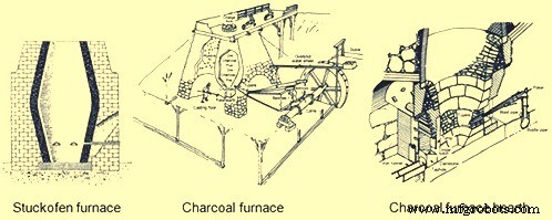
図3Stuckofen炉と木炭炉
木炭高炉の進化
大陸ヨーロッパで開発された木炭BF(図3)は、製鉄技術の次の進化が起こったイギリスにすぐに広がりました。 1565年にイギリスのモンマスシャーに建設されたBFは、主要な製鉄センターとなったディーンの森に建設された最初の炉でした。このBFは、高さ4.6 m、ボッシュで1.8 mで、2つの円錐台が出会う炉内で最も広いポイントでした。 1615 CEまでに、炉ごとに1日あたり平均約2トンの300のBFがありました。成長速度が非常に速かったため、木炭生産のための土地が完全に森林破壊されました。 1600年代には、残りの森林を保護するために法定の制限が課され、多くのBFが閉鎖されました。
北米で最初に建設されたBFは、1622年にバージニア州フォーリングクリークにありました。すべてのプラント労働者が殺害され、製鉄所がネイティブアメリカンによって破壊されたため、この炉は稼働しませんでした。北米で最初に成功した木炭BFは、1645年に始まったマサチューセッツ州ソーガスでした。このBFは、高さ6.4 mの煙突を持ち、外壁は上昇するにつれて内側に傾斜し、底部は7.9m四方でした。炉は花崗岩と他の地元の石を粘土モルタルで接着して作られました。それは、大きなベローズホイールを駆動する水がそれを特別に影響を受けやすくする湿気を防ぐために地下排水システムが切り込まれた平らな地面に置かれました。 BFは、ほぼ卵形の内部を持ち、ボッシュの上部として知られている最大直径が1.8mのスタックを持っていました。下向きに傾斜するボッシュは、鉱石、フラックス、木炭の装入を支えました。炉床と呼ばれる四角い坩堝がボッシュの底の下にあり、砂岩で裏打ちされていました(図3)。内側の裏地と外側の石積みの間に砂、粘土、瓦礫のある内壁があり、加熱と冷却のサイクル中に膨張と収縮のクッションとして機能しました。 2つの外壁には大きくて深いアーチがありました。小さい方のアーチを通り抜けて、2つの5.5mベローズと2つの羽口のノズルが通過しました。大きなアーチの下には、炉床と鋳造床の作業エリアがありました。るつぼまたは炉床は、溶鉄の貯蔵庫として機能しました。炉床は基部が460mm四方でしたが、全高1.1mに達すると530mmに広がりました。前炉床と呼ばれるその下部の突起は、2つの壁と1つのフォアストンまたはダムで構成されていました。上にあり、ダムから後退したところに、「ティンプ」と呼ばれる石のカーテンウォールがあり、その下端はダムの上部よりも低くなっています。ティンプとダムの間の開口部を通して、オペレーターは型鋳造のために鉄をはがし、リンガーと呼ばれる鉄の棒で壁に付着したり羽口の鼻の周りに堆積したスラグをこじ開けました。このような作業の損耗から保護するために、ティンプとダムの両方が鉄板で覆われていました。スラグの除去は、燃えがらのノッチと呼ばれる場所でダム石の上に液体材料をかき集めることによって達成されました。ただし、鉄を叩くには、前壁の側壁の1つとダムの一方の端の間のタップ穴と呼ばれる狭いスペースに挿入された粘土プラグを破る必要がありました。
この複雑な組積造作業に加えて、BFの建設には木材と皮革の作業が含まれていました。 BFトップと隣接するブラフの間には、チャージングブリッジと呼ばれる重い木材構造がありました。原材料は、ブラフの備蓄から手押し車で、充電ブリッジを越えてBFの上部まで運ばれました。 BFトップの3つの側面には木製のウィンドスクリーンがあり、煙、火花、時には炎を放出する充填穴に原材料を充填するオペレーターに安全な避難所を提供するために設置されました。地上レベルのBFスタックは、鋳造所と呼ばれる木製の片流れの屋根構造によって両側が包まれていました。この構造は、ベローズだけでなく、トレンチとモールドキャスティングエリアのカバーを提供しました。 2つのベローズは、オーバーシュート水車に接続されたカムシャフトによって往復運動で駆動されました。ベローズは主軸のカムによって収縮され、石で満たされた木箱からなるカウンターウェイトによって膨らまされ、それらを収容するために開けられた穴を通して鋳造所の屋根を越えて伸びる可動梁に取り付けられました。 BFは、生産された鉄1トンあたり3トンの鉄鉱石、2トンのフラックスストーン、および2.6トンの木炭を消費しました。タップ穴は1日2回開かれ、各鋳造中に約450kgの溶鉄が除去されました。溶鉄は単一の溝に引き込まれたり、砂型に入れられたりして、鍋、フライパン、ストーブプレートなどの国産品が製造されました。
上記の炭鉄の製造は、次の100年から1700年代にかけてわずかに変化しました。 BFスタックのサイズが大きくなり、ブロー装置が改良されました。 1700年代の典型的な木炭BFは、高さが9.1 m、ボッシュの直径が2.4mに拡大されました。 BFサイズの増加は、より高い爆風圧をもたらす風力供給装置の改善によってのみ可能でした。ブラストシステムの最初の改良点は、正方形または円形の木製のブローイングタブの発明であり、外部のスチールフープで一緒に保持された木製のバレルに似ていました。水車の偏心クランクには、両側に往復ピストンロッドとブローイングタブがありました。浴槽内のピストンには革を取り付けてシールを形成しました。一方のピストンが上昇して一方のタブ内の空気を圧縮しているとき、もう一方のピストンはもう一方のタブ内で下降していました。各タブの上部には、常に圧力がかかっている共通のミキシングボックスに接続された出口パイプがありました。ミキシングボックスは、圧縮空気をエアダクトまたはブラストメインに供給し、炉の羽口に導きました。典型的なブローイングタブは、直径1.8 m、高さ1.8 mで、0.14 kg /sqcmの爆風圧を発生しました。木製のブローイングタブの概念は、1760年にイギリスのジョンスミートンによってさらに一歩進められました。彼は木製の桶を最初に水車で駆動され、次に1769年に蒸気機関で駆動される鋳鉄製の桶に変換しました。蒸気駆動の送風エンジンを使用する最初のBFは、1769年にスコットランドで建設されました。蒸気駆動の送風エンジンの発明により、より高い爆風圧力がもたらされ、鉱物燃料(コークスと石炭)のさらなる使用が可能になりました。これらの1700年代の改善により、BFの生産量は1600年代のBFの1トン/日から1700年代後半までに3〜5トン/日に増加しました。これに加えて、鉱物燃料の使用により、ヨーロッパでは木炭炉の数が急速に減少しましたが、北米では、木材が大量に入手できる西部に人口が移動するにつれて、木炭鉄の生産能力が増加しました。
1800年代に、木炭鉄の生産はピークに達し、その後減少しました。 1800年代半ば、ペンシルベニア州と原生林が密集したミシガン州のアッパー半島で高品質の鉄鉱石が発見されました。この地域に建設された木炭BFは、最大かつ最高の設備を備えていました。これらのBFのスタックの高さは13.7m、ボッシュの直径は2.9mでした。羽口の数は2つから3つに増え、それぞれが炉の3つの側面にあり、タップ穴は4番目の側面にありました。ブロー装置は通常、最大直径1270 mm、ストローク1.5mの水平ブローシリンダーでした。エレベータタイプのプラットフォームホイストが充電ブリッジに取って代わり、すべての鉄鉱石とフラックスが標準充電の一部として計量されました。木炭はまだ大きな手押し車のボリュームによって充電されていました。鉄のシェルプレートが石積みの石積みをゆっくりと置き換え、天然石の裏地がアルミナレンガにアップグレードされました。
これらの木炭炉に設置された主要な技術的改善の1つは、装入装置でした。もともと、原材料はトンネルヘッドを介して口の開いたスタックに投棄されていました。 BFオペレーターは、オープントップ炉には2つの欠点があることに気づきました。1つは煙突から出る可燃性ガスをボイラーに回収できないこと、もう1つは原料の分配が炉の運転効率を低下させることです。ガスを捕獲するためのドイツでの1832年の最初の取り組みは、原料が手押し車から投棄されたときにのみ開かれた充電穴の上にヒンジ付きの蓋を設置することをもたらしました(図4)。上部スタックにある炉の側面にも開口部が配置されました。この開口部には、高炉ガスを地上に運び、補助装置で燃焼させるダウンカマーと呼ばれるパイプが取り付けられていました。
原材料の充填によるBFの非効率性の問題には、より複雑な解決策が必要であり、それはいくつかのステップで発展しました。高い燃料率によって説明されるこの非効率の原因は、BFの中央にある充填穴から微細な材料がダンプされ、粗い粒子が炉壁に転がり落ちる間、ヒープの中央に留まったためでした。これにより、BF周辺の透過性が高くなり、ガスと熱の大部分が壁を上って移動しました。これは、BFの中心にある材料が溶融の準備ができていないボッシュ領域に到達し、同時に壁での過剰なガスの流れがライニングの摩耗を促進したため、BFの操作に悪影響を及ぼしました。この負荷分散の問題を解決する最初の試みは、充電装置「カップアンドコーン」の導入でした(図4)。それは、装入穴に供給する炉の上部に固定された逆円錐形の鋳鉄漏斗で構成されていました。この円錐は喉の直径の約50%でした。コーンの中には、カウンターウェイトの反対側の支点ビームに吊るされた鋳鉄製のカップがありました。カウンターウェイトに接続されたウインチを使用して、カップを手動で持ち上げました。この装置はガスを捕らえることに成功しましたが、それでも大量の粗い材料が壁に転がりました。カップアンドコーン装置の次の変更は、鋳鉄製の円錐台を炉内に吊るすことでした(図4)。これにより、原材料のピークが壁の近くに移動し、粗い粒子も炉の中心に転がり、中心の透過性とガスの流れが改善されました。
カップとコーンを完全に排除した充電の次の進化のステップは、下向きに開いた逆コーンを炉に吊るすことでした(図4)。これは最初のベルタイプのBFトップでした。このベルは壁の頂上を押すことに成功し、周辺のガスの流れを減らし、中央のガスの流れを増やしましたが、ベルを下げるたびにBFガスが煙突から逃げました。これに対する解決策は、充電穴用のベルと蓋を用意することでした。手押し車から材料が排出されたとき、蓋は上がっていたが、ガスをBFに保持したままベルを閉じた。次に、蓋を閉め、ベルをダンプしました。これにより、ガスもBFに保持され、同時に適切な負荷分散が得られました。これらの改善の結果、BF内の物理的および化学的反応効率が向上し、燃料要件が削減され、生産性が向上し、耐火物のライニングの摩耗が減少しました。
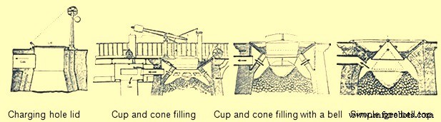
図4BFトップ機器の進化
多くの設計改善によりBFの生産量が増加したため、液体製品(鉄とスラグ)の除去が問題になりました。木炭BFの生産量は、1日あたり1トンから25トンに増加しました。この高いトン数は、タップ穴の前にある1つのトレンチを介して1日2回のキャストでは処理できませんでした。キャストハウスの建物のサイズは、幅約12 m、長さ21mに拡大しました。鋳造所には、鋳鉄とスラグ除去のための別々の領域が含まれていました。鉄の除去のための側面は、炉の正面から砂で満たされた鋳造所の床に向かって下向きに傾斜したトラフと呼ばれる大きな溝で構成されていました。その後、2つのランナーシステムに流出しました。各システムのメインランナーは、キャストハウスの長さと平行に走っていました。このランナーが下り坂を傾斜するにつれて、一連のダムが定期的に作られました。各ダムの前に直角に、「雌豚」と呼ばれる小さなランナーが砂の中に形成されました。次に、この雌豚から「豚」と呼ばれる多数の虫歯がありました。これらの名前は、このシステムが母親を授乳している子豚の列のように見えたために適用されました(図5)。キャストハウスの床の湿った砂にD字型の木型を押し込んで作られた雌豚と豚が平行に並んでいました。キャスト中、各雌豚とその豚が溶鉄で満たされると、メインランナーの砂ダムが棒でノックアウトされ、溶融金属が次の雌豚と豚のベッドに向かって下り坂を走りました。 BFをより頻繁にキャストできるようにする2つの完全なシステムがありました。片面が溶鉄で満たされているので、もう片面は豚を取り除き、ベッドを改造しました。
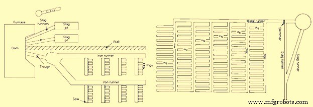
図5キャストハウスの豚舎
キャストハウスの反対側はスラグ除去に使用されました。スラグは常にダムの正面を越えてスラグランナーを下り、スラグピットに流れ込んでいました。 BFの前部にあるスラグダムは2つの半分に分割され、各半分は別々のスラグランナーとスラグピットに供給されていました。スラグピットは砂の大きな窪みで、底に尾根がありました。これらの尾根は、固化したスラグを除去するときに破壊点として機能しました。一部のキャストハウスでは、大きなスラグを持ち上げるためにジブタイプの木製クレーンが使用されていました。キャストハウスのオペレーターは、スラグ層が厚くなりすぎることに気付いた場合、通常、液体スラグの中央にバーを配置しました。次に、スラグがバーの周りで冷やされると、ロープまたはチェーンがその周りに巻き付けられ、スラグの大きな断片がクレーンによって持ち上げられました。スラグ除去のために、2つの完全なスラグシステムもあり、1つは使用中に、もう1つは洗浄して準備することができました。
「鋳造」という言葉の由来は、溶鉄が炉から「鋳造」されたという認識に由来すると理解されています。鋳造作業は2つの部分で構成されています。最初の部分では、液体スラグがBFで形成されている間、液体スラグは、タイプとダムの間をスラグランナーとピットに流れるのに十分な高さに達するまで、溶鉄の上に浮かんでいました。鋳造の2番目の部分は、炉の炉床からの溶鉄除去の除去でした。これは、爆風を遮断し、先のとがったバーをハンマーでタップ穴に打ち込むことから始まりました。溶鉄はトラフを流れて、連続する各雌豚とその豚に流れ込みました。溶鉄の流れが止まったら、砂と耐火粘土または砂と石炭の湿った混合物でタップ穴を手動で塞いだ。その後、爆風は炉に戻されました。
鋳造後、鋳造所のオペレーターは固化した鉄を豚床から取り出しました。豚が十分に冷えたとき、彼らは派遣のために送り出されました。このサイクルは1日6回繰り返され、各鋳造で4〜6トンが生産されました。生産された銑鉄は、さまざまなグレードに分類されました。木炭鉄は硫黄値が低いため、1800年代の拡大する鉄道を支えるために必要なレールや鉄道車両の車輪を製造するために使用される頑丈なねずみ鋳鉄になりました。
木炭BFは、1800年代後半に廃止されました。これは、その生産コストが、鉱物ベースの製鉄慣行から生じる競争に対応できなくなったためです。
鉱物燃料に基づく製鉄
木炭の製鉄を維持するために必要な原生林の枯渇により、代替燃料源を探すことが必要になりました。この代替燃料は、瀝青炭、無煙炭、コークス、さらには泥炭の形で提供されました。コークスと無煙炭の開発は互いに並行して行われ、1700年代から1800年代にかけて木炭の生産と共存していました。瀝青炭と泥炭の使用は制限されており、主要な製鉄燃料になることはありませんでした。木炭生産による森林破壊が最初に起こったので、製鉄のための鉱物燃料の使用はイギリスから始まりました。
1708年、アブラハムダービーはシュロップシャーで小さな木炭BFをリースし、1709年までにコークスを生産していました。 1709年から1718年まで、この炉でコークスは木炭と混合され、1718年にはBFは100%コークスを使用していました。 1750年まで、定期的にコークスを使用する3つのBFはダービー家に属していました。コークスの使用は1750年から1771年の間に広がり、合計27のBFが鉄の生産にコークスを使用しました。 The use of coke increased the production of iron since it was stronger than charcoal. It could support the weight of more raw materials and thus the size of BF could be increased. Coke also improved permeability in the BF, allowing a larger volume of wind to pass through the furnace. This larger volume of compressed air was provided by the steam engine and blowing cylinders.
The use of coke in continental Europe spread slowly. Coke was used in Le Creussot, France in 1785, Gewitz, Silesia in 1796, Seraing, Belgium in 1826, Mulheim, Germany in 1849, Donete, Russia in 1871 and Bilbao, Spain in 1880. In North America, the first use of 100 % coke as the fuel was in 1835 at Huntington, Pennsylvania. However, since 1797, coke was mixed with other fuels in BFs of US.
The efficient use of coke and anthracite in producing iron was accelerated not only by the use of steam-driven blowing equipment but also by the invention of preheating of the air being blown in the BF. In the beginning of the 19th century, it was believed that use of cold blast improved both the quantity and quality of pig iron since it was observed that the production of the BFs was more in winter months and it was erroneously concluded that the lower blast temperature was the reason. But the BF performance improved during the winter months due to the fact that the air was having lower humidity so that more combustion of fuel was supported by a given volume of air blown into the furnace.
In 1828, James Neilson patented his invention of supplying preheated air blast to the tuyeres. The heating equipment was a simple wrought iron box having dimensions 1.2 m x 0.9 m x 0.6 m. This wrought iron box was externally heated. The maximum blast temperature which could be attained with this box was 93 deg C and one box was needed for each tuyere. In 1832, Neilson improved his invention by constructing a larger oven by joined flanges, formed a continuous length of 30 m and provided a heating surface of 22.3 sq m. This oven, which was fired with solid fuel, produced a hot blast temperature of 140 deg C. Since this invention, continuous modification and improvement in the hot blast ovens were made and by 1831, Dixon developed a taller oven with U-shaped pipes that supplied hot blast at 315 deg C. By 1840, about 55 % of pig iron at Great Britain was produced with hot blast.
With the increase in the hot blast temperature, there was decrease in the quantity of fuel needed and increase in the BF production. However the hot blast equipment needed a lot of maintenance. The cast iron pipes supported within a brick oven had different expansion characteristics, which resulted in several cracked pipes. Another issue was that the delivery equipment used for the cold blast, which consisted of solid tuyeres and flexible leather joints between pipes, could not withstand the high temperatures. Another issue with the original hot blast systems was the increased cost of solid fuel to heat the ovens. These issues helped further improvements in hot blast equipment. First, solid fuel used for heating was replaced with BF gas. Initially primitive heat exchanger type hot blast equipment was built on top of the BF and simply used the waste heat to preheat the cold blast running through the cast iron pipes. Then the BF gas from the furnace top was conveyed to the hot blast oven where it was burned to generate heat. This type of hot blast oven became quite complex with numerous rows of vertical pipes. The issue of cracking of the cast iron pipes was tackled by eliminating the pipes and using refractory. For using this method, 2 to 4 stoves were installed for each BF. As one stove was being heated by the burning the BF gas, another was being drained of its heat by heating of the cold blast. In 1854, the Cambria Iron Works was the first plant in the US to use regenerative stoves. The stoves were constructed of iron shells, internally lined with refractory and containing refractories with multiple passages for the blast. A typical stove of this design had 186 to 232 sq m of heating surface. These stoves were representative of those produced by Cowper and Whitwell in 1857. The Whitwell stoves erected in 1875 were 6.7 m in diameter, 9.1 m high and had a total heat surface of 8546 sq m. These were the first stoves to use hexagonal refractory checkers, cast iron checker supports, and a semi elliptical combustion chamber to improve distribution of gas through the checkers. These stoves could supply hot blast to the BF with temperatures of 454 deg C to 566 deg C. This stove design has remained basically the same till date with minor modifications in refractory type, checker shape and stove size.
The other improvement in equipment required by the use of hot blast was the design of the tuyeres and the tuyere stock. The solid cast iron or cast copper tuyeres used on cold blast furnaces were replaced by water cooled tuyeres which were hollow, conical shaped castings which had water circulating through their interior. The pipes from the blowing engines to the tuyeres, which were jointed with leather on cold blast furnaces, were redesigned with metal-to-metal seats. As hot blast temperatures increased the inside of these blast mains and tuyere stocks were lined with refractory, which required an overall increase in size.
The use of hot blast was applied to both coke and anthracite furnaces. As blast pressure increased with new blowing engines, it was found that anthracite could be charged with charcoal to improve the BF productivity. During 1986 the first attempt was made to use anthracite in a cold blast furnace in eastern France. This attempt failed since the ignited anthracite broke up into small pieces and blocked the blast from entering the BF. The evolution of coke iron making and anthracite iron making paralleled each other in the US during the 1800s. In 1826, a small BF was erected in Pennsylvania to operate exclusively on anthracite coal. This practice was unsuccessful both there as well as at other places in the US. During 1833, Dr. Frederick Geissenhainer successfully used hot blast in experiments to smelt iron with anthracite coal. In 1836 the Valley furnace in Pennsylvania used 100 % anthracite and in 1837, George Crane produced 36 tons of anthracite iron per week from one of his BFs at South Wales. David Thomas was the most successful iron maker in using the anthracite in the BF. In 1838 he came to the US and built the Catasauqua BF in 1840 (Fig 6). The furnace was 10.7 m square at the base with 3.6 m bosh and a height of 13.7 m. The hot blast stoves, fired with coal, were capable of heating the blast to 315 deg C. Since this BF successfully produced 50 tons of good foundry iron per week, the furnace was used as a model for the construction of blast furnaces built for using anthracite as a fuel. By 1856 there were 121 anthracite furnaces in operation in the US.
Other fuels were also tried for iron making in the BF. These were peat and bituminous coal. Peat BFs were similar to charcoal furnaces and typically were no higher than 6.7 m. Because the peat was physically weak, the use of these furnaces was located near to the peat deposits and they never played a major role in iron making evolution. Bituminous coal had been used to supplement charcoal prior to the introduction of hot blast. In the 1830s, splint coal was used in Scottish hot blast furnaces. In 1856, there were 6 BFs in Pennsylvania and 13 BFs in Ohio using bituminous coal. The bituminous coal era of iron making was essentially finished by 1895. This method of iron making never became a major force since the coal broke up into small pieces as the BFs were made larger and used higher blast pressure. With coke being the strongest and most available fuel, the evolution of 100 % coke furnaces continued. However there were initial setbacks probably due to low strength coke. By the 1840s coke quality had improved through the use of beehive ovens. In 1867, the ‘Monster’ blast furnace was built at Norton, England. This coke furnace was 25.9 m high, 7.6 m across the bosh and had a working volume of 735 cum. An example of a large coke furnace in the US in 1884 was the Etna furnace located near Pittsburgh. This furnace was 21.3 m high, 6.1 m in diameter at the bosh, 3.4 m in diameter at the hearth and had seven 7 inch (178 mm) tuyeres, three Whitwell stoves and three blowing cylinders that were 2.1 m in diameter. This BF produced 115 tons/day in 1881, 161 tons/day in 1882 and 182 tons/day in 1883. The coke furnace design at this time was very similar to the anthracite furnaces of the same era (Fig 6).
Further evolution of coke blast furnace
The evolution of BFs using 100 % coke continued with major improvements being made between 1872 and 1913. Several technological improvements were made which were centered on the hard-driving BF practice of using more powerful blowing engines, higher blast temperatures, bigger furnaces, better charging equipment, improved raw material preparation and production of clean BF gas.
Blowing equipment design and capacity was a major step to higher production in the hard-driving BFs. Blowing cylinders were replaced with large steam reciprocating blowing engines capable of providing a greater volume of blast air at a significantly higher blast pressure. These blowing engines were of the walking beam, steam condensing type. The steam cylinder’s piston rod was connected to a gallows beam and then by a crank to a heavy, large diameter flywheel. The blowing cylinder’s piston rod was connected to the other end of the gallows beam and each stroke of the steam cylinder provided a corresponding stroke of the blowing cylinder. Cold blast pipes were fitted to each end of the vertically positioned blowing cylinder so that air was compressed on both directions of the stroke. The flywheel provided momentum for the return stroke of the steam cylinder. The air that was compressed in this manner left the cold blast pipes and entered the cold blast main which connected to the hot blast stoves. Prior to this type of blowing engine the normal blast volume was 210 cum/min at a blast pressure of 0.28 kg/sq cm. This blowing engine could produce 456 cum/min at a blast pressure of 0.64 kg/sq cm. Then in 1910, the final major step in blowing engine improvement was implemented in the form of a turbo-blower. The first turbo-blower was installed for the BF of the Empire Steel Co. in New Jersey and was capable of delivering 636 cum/min of air blast. This turbo- blower was the direct ancestor of the modern turbo-blower which can deliver up to 7500 cum/min of blast volume at 4.00 kg/sq cm of blast pressure.
Another major improvement in high productivity BFs was to increase the charging capacity. In the 1870s the BFs were equipped with water driven elevators. In 1883, the first skip hoists were installed. Skips have become larger and faster into the 20th century and existed as both buckets and cars mounted on wheels. In the early 1960s some skip charging systems were replaced with large conveyor belts.
The improvements in furnace charging capacity also included automatic coke charging systems, scale cars in the stock house, two bell tops and the rotating distributor (Fig 6). Automatic stock line measurement was invented in 1901 by David Baker. In 1903, JE Johnson also began to measure top gas temperature and its analysis.
By 1850 as the furnace size increased, the furnace top could be closed. A single bell and hopper arrangement could be used for charging the furnace that kept the top of the furnace closed and sealed. The single bell and hopper system permitted large quantity of gas to escape every time the bell was opened. Soon a second bell and hopper was added above the first so that a gas tight space could be provided between the two bells to prevent the blast furnace gas escaping when the small bell was opened. The upper bell and hopper did not have to be as large as the lower one because several charges could be deposited through it on the lower bell and the upper bell could be closed before the lower bell was opened for dumping the charges in the furnace
Attempts to improve burden distribution occurred in the early 1990s with the McKee rotating top. After each skip of material was charged onto the small bell, the small bell hopper was rotated 60 deg, 180 deg, 240 deg, 300 deg, or 0 deg. This prevented a peak of raw material directly below the skip bridge which had resulted in uneven gas distribution and uneven lining wear. The next attempt to improve burden distribution was done in Germany in the late 1960s. This was accomplished by installing movable panels at the throat of the BF that could be set at different angles for ore or coke. This movable armour has been installed on large numbers of BFs.
The two bell system continued to be the only charging system for the blast furnaces around the world till S.A. Paul Wurth in Luxembourg, developed bell less top (BLT) charging system and the first successful industrial application of BLT charging system was in 1972. This equipment used air tight material hoppers that fed a rotating raw material delivery chute which could be set at numerous angles during the hopper discharge into the furnace. The result was the almost unlimited placement of each material anywhere on the burden surface which allowed the operator to achieve maximum fuel efficiency.
The BLT charging system took over from two bell charging system since it provided a number of advantages to BF operators. During 2003, Siemens VAI introduced Gimbal concept of charging.
Another attempt in the direction of the continuous improvement of the BFs for increasing the production was towards improvements in the cleaning of BF gas. As blast volume and pressure increased at the tuyeres, the velocity and volume of gas leaving the BF top also increased. More flue dust was then carried by this waste gas and if it was not removed, it began to plug up stove checkers which subsequently restricted blast volumes to the furnace. The first step in gas cleaning was the introduction of the dust catcher in the 1880s. With the introduction of the soft iron ores in 1892, the dry-type dust catcher was not sufficient. In 1909, Ambrose N. Diehl introduced a wet gas cleaning system. It consisted of a series of nine high-pressure spray towers and a set of four rotary washers. From 1914 to 1924, several types of tower washers equipped with multiple banks of sprays and baffles were tried at various furnaces. Gas disintegrators which contained high speed rotary drums were also tested in 1907. In 1929 electrostatic precipitators were used successfully at South Works of U.S. Steel. Today, combinations of tower-type gas washers, Venturi scrubbers and mist eliminators are the most common types of gas cleaning equipment.
The newest wet gas cleaning equipment is an annular gap scrubber which cleans the gas as well as controls top pressure. The final result of all these gas cleaning improvements was a decrease in stove checker brick hole diameter with an increase in stove size because plugging with dirt had been virtually eliminated. The resulting increase in stove heating surfaces has ultimately allowed modern stoves to deliver up to 1270 deg C hot blast temperature. The associated top pressure control allowed by modern gas cleaning equipment has resulted in furnace top pressures up to 2.3 kg/sq cm. This higher top pressure in turn increases the density of gases, decreases gas velocity and increases gas retention time in the furnace, yielding better gas-solid reactions, improved reducing gas utilization and lower fuel rates.
Recently, on the newly built and reconstructed BFs, particularly in China, dry cleaning of BF gas by bag filters has found the wide application. Dry cleaning of gas has several advantages over wet gas cleaning using scrubbers and Venturi tubes.
The quest for higher production rates in the late 1870s and onwards forced changes in the size of the furnace size and its configurations. In the 1870s, the furnaces were 22.9 m high. In 1880, the BF size increased to 24.7 m high, 6.1 m bosh diameter and 3.4 m hearth diameter. It produced 120 tons/day with a 1574 kg/ton coke rate. Just ten years later, in 1890, BF was constructed with a stack 28.0 m high and with 6.7 m bosh. It produced 325 tons/day. Then in another 10 years, in 1901, BF was started with similar stack and bosh dimensions as earlier furnace but the hearth diameter was increased to 4.4 m. This furnace produced 463 tons/day at 1113 kg/ton coke rate. The other subtle change with these size increases was the lowering of the bosh/stack bend line and the steepening of the bosh angle. This change was detrimental as the furnaces saw poor burden descent and slipping with these bosh angles. To eliminate these problems, the hearth diameter of these size furnaces was increased up to 6.7 m in 1927. This bigger hearth furnace produced 880 tons/day at a coke rate of 922 kg/ton. The first 1000 ton/day furnace was commissioned in 1929. This furnace was equipped with a hearth diameter of 7.6 m. In 1955, Great Lakes’ A furnace was the largest in the world with a 9.2 m hearth and 24 tuyeres. The next leap in blast furnace size increase occurred during the 1960s as Japan rebuilt their outdated steel plants. Today, furnaces with 15 m hearth diameter, 40 tuyeres and four to five tap holes, are common in Europe and Asia.
Along with the larger furnaces, higher blast temperatures and increasing driving rates, came the need for better BF refractory lining and cooling systems. In the 1880s a high duty fireclay brick with around 40 % alumina and 46 % silica was typical. However, C refractories were used in German BFs since 1886.
While refractory technology was relatively unknown at this time, methods to cool the lining seemed to be the answer to the wear problem. Beginning about 1880, there were simultaneous developments in efforts to maintain furnace linings by means of pipe coils around the bosh or by cooling plates embedded in the brick. One of the first uses of a bronze bosh plate is believed to be an installation made by Julian Kennedy at one of about 1890. An early reference to the use of water-cooled hearth jackets is on the furnace was in 1882. At this time, cooling of the hearth sidewalls and bosh was the concern and stack cooling was not felt to be necessary.
Fritz W Lurman, a well-known blast furnace man of the time opined in 1892 that ‘irrespective of the use of so called refractory materials, the best means of maintaining the walls of the blast furnace is with cooling water’. Coolers with water circulating in them are installed between the shell of the blast furnace and the refractory lining in the upper part of the furnace to protect these components from heat radiation. In addition to having its own coolers, the part of the shell adjacent to the hearth and the bottom of the furnace is also cooled in some furnaces on the outside by water sprays.
Function of blast furnace cooling system is to cool the furnace shell and prevent from the overheating and subsequent burn through. Cooling system removes the excess heat generated in the blast furnace which is otherwise loaded on the shell. Cooling system thus prevent the increase of the shell and lining temperature. Various methods exist for cooling of the shell for the blast furnace. In earlier times, cooling boxes of different size, number and design were used for transferring heat of the furnace to a cooling medium in conjunction with external cooling (spray cooling, double shell). Blast furnaces with cast iron cooling staves are operating since mid-1900s. Cast iron stave cooling was originally a Soviet discovery from where it travelled initially to India and Japan. By 1970s, cast iron cooling staves have attained world-wide acceptance. Since the introduction of these cast iron stave coolers, the development work of blast furnace cooling got accelerated and today a wide variety of coolers are available for the internal cooling of the furnace shell to suit extreme condition of stress in a modern large high performance blast furnace.
The higher charging rates were also wearing out the throat of the furnace faster. In 1872, iron or steel armour was built into the brickwork of the furnace throat at a furnace. Since that time, various types of armour have been used in the stock line area.
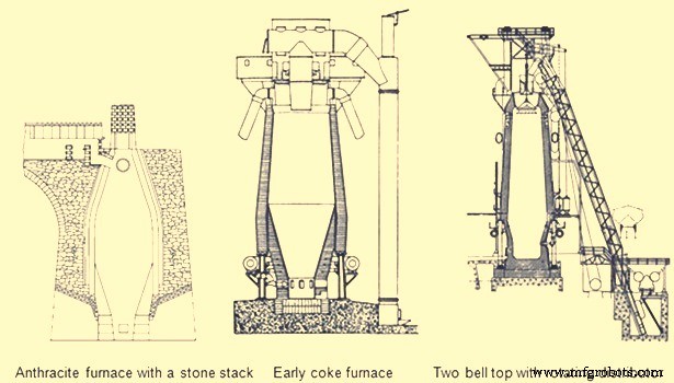
Fig 6 Early blast furnaces
The first important developments in brick making technology did not occur until the 1900s. In 1917, the first machine-made brick was introduced with its resulting increase in density and strength. In 1935, vacuum pressed bricks further improved brick quality. In 1939, super-duty alumina brick containing up to 60 % alumina was first available. In the 1930s, carbon blocks were used in German furnace hearths. Today many varieties of alumina, carbon, and silicon carbide refractories are available for BF lining. The improvements in furnace cooling and lining have increased typical campaign lengths from two years in the 1880s to more than ten years in the 1990s. Today campaign life of BFs has further increased to 20 years.
Another area of the BF which was forced to change with increased production was the casting operation. The old style tymp and dam open front of the furnace was no longer adequate. In 1867, the Lurman front was patented to eliminate the tymp and dam. It consisted of a cast iron panel which was water cooled and had separate openings for iron removal (still known as a tap hole) and for slag removal (known as the slag or cinder notch). This design was changed by the 1880s by rotating the slag notch 90 deg from the tap hole. Both the tap hole panel and slag notch panel were water cooled. By separating these two liquid tapping points, more room was available to set up the furnace for the increasing number of casts required at higher production rates. The area in front of the tap hole was completely available for pig beds while the slag pits were moved around to the side of the furnace (Fig 5). During normal operation, the slag notch was opened with a bar as the liquid slag level approached the tuyeres. The slag was flushed into pits or special slag cars. When the slag notch blew wind out of the opening, it was closed with a manual stopper. By tapping the slag off between iron taps, a greater volume of the hearth was available for liquid iron which resulted in larger cast tonnages. The iron casting process in the 1880s did not change much from previous operations but pig beds were bigger and in 1909 a slag skimmer was installed to skim the floating slag off of the iron as it flowed down the trough.
In 1896, the installation of a pig casting machine invented by EA Uehling finally brought about the complete elimination of the pig bed in the cast house. Next the open-top brick lined ladles were introduced. These ladles carried about 10 tons to 100 tons of hot metal and required the furnace and cast house to be elevated above ground level so the ladles could be placed under the cast house floor. Though the pig beds have got eliminated but troughs and runners remained and spouts going into the ladles were added to the cast house. In 1915, there was first use of the torpedo type ladles. These railroad mounted ladles carried 90 tons but were increased to 150 tons by 1925. Today, the iron ladle design is similar but capacities up to 400 tons are available. Open-type ladles mounted on rail cars are still used today.
Prior to 1890, the tap hole was opened with a bar and sledge hammer. Then in 1890 the first pneumatic rock drill was used. The tap hole was manually stopped with wind off the furnace until 1914 when HA Berg developed the remote controlled mud gun which pushed a clay plug into the furnace with a wind on. In 1906, the first oxygen lancing was used to melt skulls in the tap hole. Modern BFs have evolved to include remote controlled tap hole drills, hydraulic mud guns, cast house slag granulation units and iron tilting spouts to feed an unlimited number of iron ladles. BFs may also have from one to four tap holes and two to six slag pits depending on their size. Removing the bottleneck in the cast house allowed the first 1000 ton/day operation in 1929 and led to 1990s production levels of 12,000 ton/day.
A parallel line of improvement activities which rapidly evolved starting in the late 1800s was iron ore preparation. Iron ore used in iron making consists of many geological forms such as red hematite, specular hematite, magnetite, limonite, fossil ores, bog ores and carbonates. The metallic iron content of these ores ranges from approximately 30 % in the bog ores to 72 % in some hematites. All iron ores are mixed with other compounds in the earth which are undesirable in the smelting process. Beginning in the 1700s, iron ore was roasted with charcoal in open pits or enclosed kilns. The object of roasting or calcining was to liberate all volatile constituents, such as water, carbonic acid or bituminous substances, and to soften and crack the ores, making them more permeable to reducing gases. In the 1800s, iron ore screening was introduced to more closely size the ore for improved gas permeability inside the furnace. At first, hand screening equipment was used but, by the 1870s, steam-driven ore washers consisted of one or two drums that were perforated with holes or slots for the fine material to exit with the wash water while the final sized and washed ore exited the inside of the drum into a wheelbarrow or stockpile.
As iron production increased, the purest iron ores were depleted in many areas so lower grade ores had to be mined. These ores had undesirable impurities and methods to concentrate these ores to higher iron percentages were required. In 1880, Thomas A. Edison obtained a patent for an electromagnetic separator. A demonstration plant was built in Michigan and produced 893 tons of magnetic concentrate in 1889.
Pilot plants to pelletize taconite concentrates were built in 1948. By 1956, two commercial-scale taconite mining and processing operations were producing pellets. The first straight grate pellet machine was made in 1956 and the first grate-kiln pellet machine was put into operation in 1960. Pelletizing technology spread throughout the world from the US. The newest development in pelletizing was the introduction of raw limestone, dolomite or olivine into the pellet to improve its metallurgical properties which, in turn, improved BF productivity and fuel rates.
Iron ore agglomeration also took a separate route from pelletizing earlier in the 1900s. Sintering process originated in the nonferrous industry as a batch process in the late 19th century. Up to the 1950s, most sinter had a basicity ratio of less than 1.0. However, over the next fifteen years, it was realized that a basic sinter with a basicity ratio of more than 1.0 brought a pre-calcined flux source into the BF which resulted in a fuel rate savings.
One of the final technological improvements in iron making over the last 100 years has been tuyere level injectants. The first recorded use of injectant was in 1871 when there was a chilled hearth on the Morgan charcoal furnace. Because blast could not enter the tuyeres due to chilled material, a hole was punched through the furnace wall above the salamander and a large tuyere was installed. Coal oil was then forced under pressure into the tuyere from a pipe running from the top of the furnace. Six days and seven barrels of oil later the salamander had been melted and the furnace was running smoothly. In the first decade of the 1900s early tests with oxygen injection were made in the small BF in Belgium. The first large scale oxygen enriched blast was used in 1951. The benefits of pure oxygen injection are increased BF production due to increased fuel burning capacity and an ability to use more hydrocarbon tuyere injectants. The evolution of hydrocarbon injectant occurred in the 1940s and 1950s. In 1944, William L. Pogue submitted a patent for the use of coal injection. Then in 1953, natural gas injection was implemented. In the early 1960s, injection of oil and tar through lances was developed at numerous steel companies after substantial coke savings were proven by testing in an experimental BF in 1959. By 1967, a large number of the BFs were using some form of fuel (mostly pulverized coal) injection. Today, many BFs use fuel injectants 40 % to 45 % of the fuel rate. The final tuyere injectant, which evolved concurrently with fuel injection, was moisture injection. Historically, hot blast temperatures were limited as excessively high temperature combustion zones resulted in poor burden descent. The injection of moisture consumed coke more rapidly than air alone and produced a gas that was both richer in carbon monoxide and hydrogen and was less dense. These factors improved the rate of heat transfer between gases and solids and the rate of reduction of the burden in the furnace stack, which resulted in a smooth running furnace.
The combination of moisture injection, fuel injection and oxygen injection permitted the increase of hot blast temperature and the use of all of these tuyere level variables further improved productivity and reduced fuel rates in modern BFs.
Evolution of BF iron making as a science
Historically, iron making was more an art than a science. Early iron producers learned their trade through years of training from the previous generation. Many improvements in iron making practice were based on instinct or pure luck. However, by the mid-nineteenth century, science was creeping into the developments in iron smelting.
Charles Schinz of Germany, one of the earliest researchers of chemical and physical phenomena occurring inside a BF, attempted to make quantitative mass and energy balances of BF operation but he was severely limited by the lack of accurate thermodynamic data. He conducted laboratory experiments to determine heat capacity and heats of formation and was apparently the first to determine the reducibility of iron ore. He defined different zones of the BF and the major chemical reactions taking place in each zone. The results of his work were published in 1868.
Several principles which are recognized today were postulated by Sir Lothian Bell, during the late 1800s. He published a book in 1872 which is recognized as the first text book on BF iron making. In 1884, he was seemingly the first to document the function of the different slag components and their effect on melting temperature. He also observed that BF slags are complex structures and there is a range of slag compositions which results in its good fluid properties and desulfurizing capability. His most important contribution was his understanding of chemical reactions. He recognized the importance of CO and CO2, and was the first to start defining equilibrium in the Fe-O-C system. Further, Bell discussed preheating and pre-reduction of iron ores and the importance of the furnace stack where these reactions occurred. He also made carbon, oxygen and nitrogen balances of the BF operations and showed that some of the charged carbon was consumed in the stack by CO2 in the ‘solution loss’ reaction.
A contemporary of Bell was ML Gruner, a professor of metallurgy in France, further expanded Bell’s methods of determining BF heat balances by comparing many different furnace operations. He also believed that the minimum fuel rate for BFs would be achieved when solution loss was eliminated.
JE Johnson, Jr. was the first American scientist to explore the BF process and published two books on BF design and operation in the early 1900s. He applied the first and second laws of thermodynamics to iron making and explained how fuel rate was impacted by blast temperature. He postulated that there was a critical furnace temperature above which a minimum amount of heat is required. This minimum amount of heat he called ‘hearth heat’. In his book, published in 1913, Johnson produced a diagram showing chemical reactions and isotherms in the BF. The application of the critical temperature and hearth heat concepts further convinced furnace operators that the BF process was rational and predictable.
During the period from 1920 to 1930, the flow of solids and gases in the BF was studied extensively by a group of workers named PH Royster, SP Kinney, CC Furnas, and TL Joseph. This group was interested in physical and chemical phenomena occurring in BFs and in order to understand these phenomena they felt it was necessary to sample and probe operating furnaces. Their work started with a small experimental BF and spread to commercial furnaces. The results of their studies showed that the flow of gases and solids was not uniform across any horizontal plane in the BF and that improving gas-solid contact in the stack of the furnace could significantly increase the efficiency of the iron making process. Furnas and Joseph continued this work and determined that raw material size and reducibility was critical in gas-solid reactions. This important work led to the understanding of burden distribution and the optimization of iron ore sizing as it impacts both reducibility and permeability.
In 1962, R. Stephenson explained the role of solution loss. Previously, it had been thought the production of CO by reacting with CO2 and carbon was a waste of fuel. Stephenson pointed out that iron oxide reduction is a combination of indirect reduction and direct reduction and that indirect reduction followed by solution loss is direct reduction. Using these considerations to determine carbon rates for all combinations of these two reduction routes as a function of solution loss, results can be plotted on the ‘carbon-direct reduction diagram’. In the 1960s and early 1970s, the best applications of these BF theories were put into practice in Japan. Currently, the Japanese improvements have spread in the form of large, highly automated BFs to other places.
The theory and practice of iron smelting technology have come a long way in the last 4000 years. The transition from sponge iron produced in forges to liquid iron produced in BFs in the 1300s was the first major step in advancing iron making technology. Then came the change from cold blast, charcoal furnaces to hot blast, coke furnaces in the mid-1800s which brought iron making into the modern era. The better understanding of iron making reactions and improved equipment evolved into the hard-driving furnace operation centered in the 1880s to 1900s. Finally, the revolution in scientific applications to iron smelting, the installation of more sophisticated equipment, and the advent of electronically controlled systems has accelerated BF iron making into the current state as demonstrated by the operation of around 12,000 tons/day BFs with fuel rates less than 460 kg/ton.
製造プロセス