


引張試験中の鉄鋼材料の挙動
引張試験中の鉄鋼材料の挙動
鉄鋼の機械的特性は、引張試験によって評価されることがよくあります。テスト手法は十分に標準化されており、最小限の機器で経済的に実施できます。鉄鋼材料は構造用途で使用されているため、関連するコードおよび規格の要件を満たす引張特性を備えている必要があります。コードと規格のこれらの要件は、最小強度と延性レベルです。このため、引張試験で得られる情報は十分に活用されていないことがよくあります。ただし、引張試験の結果に影響を与える冶金学的相互作用の多くを直接調べることで、試験データの有用性を大幅に向上させることができます。これらの相互作用の調査、および熱処理、表面仕上げ、試験環境、応力状態、予想される熱機械的暴露などの冶金/材料/アプリケーション変数との相関関係により、の利用の効率と品質の両方が大幅に向上する可能性があります。エンジニアリングアプリケーションにおける鉄鋼材料。
鉄鋼材料の引張試験は多くの理由で行われます。引張特性は通常、品質を確保するために材料仕様に含まれ、一軸引張以外のさまざまな形態の荷重中のこれらの材料の挙動を予測するためによく使用されます。引張試験の結果は、通常、エンジニアリング用途のこれらの材料の選択に使用されます。これは、エンジニアリングアプリケーションでこれらの材料を選択、認定、および利用するための機械的特性データを開発するための比較的簡単で安価な手法を提供します。このデータは通常、特定の用途に対するこれらの材料の適合性を確立するため、および/または他の代替材料との比較の基礎を提供するために使用されます。
鉄鋼材料の弾性率は、試験サンプルが伸びる速度(ひずみ速度)に依存します。指定された量の塑性ひずみが発生する降伏強度(YS)または応力も、試験ひずみ速度に依存します。材料組成、結晶粒径、事前の変形、試験温度、および熱処理も、測定されたYSに影響を与える可能性があります。通常、YSを増加させる要因は、塑性変形も妨げるため、引張延性を低下させます。ただし、この傾向の注目すべき例外は、結晶粒径が小さくなるとYSの増加に伴う延性の増加です。
いくつかの構造材料は、引張試験中にひずみが発生すると、延性プロセスによって破壊されます。破面は、マイクロボイドの合体または組み合わせによって形成されます。これらのマイクロボイドは通常、塑性変形プロセス中に核形成し、塑性変形プロセスが高度に局所化された後に合体が始まります。ひずみ速度、試験温度、および微細構造は合体プロセスに影響を与え、選択された条件下(温度の低下など)では、破壊は延性から脆性プロセスに移行する可能性があります。このような遷移は、強度測定からは気付かない可能性のあるこれらの材料の有用性を制限する可能性があります。
鉄鋼材料の弾性挙動
鉄鋼構造物は通常、建設に使用される材料が通常の使用条件で弾性荷重を受けるように設計されています。これらの荷重により、材料に弾性または可逆的なひずみが生じます。強風時の高層鉄骨造建物の揺れは、弾性ひずみが目立ちやすい一例です。自動車の車軸の曲がりや車両の通過に伴う橋の伸びは、目立たない弾性ひずみの例です。ひずみの大きさは、荷重を支える材料の弾性係数に依存します。弾性率は一般に引張試験では決定されませんが、引張挙動を使用して、鉄鋼材料の選択と使用における弾性特性の重要性を示すことができます。
鉄(Fe)(207 GPa)のヤング率は銅(Cu)(117 GPa)の約2倍、アルミニウム(Al)(69 GPa)の約3倍です。ヤング率の値が高いため、Feで作られたコンポーネントは、コンポーネントに同等の負荷がかかったときに、CuまたはAlで作られた同様のコンポーネントよりもたわみが少なくなります。例として、引張試験中、455 kgに負荷されたFe、Cu、およびAlの直径12.8 mmの引張ロッドの弾性引張ひずみは、Feで0.00016 mm / mm、Cuで0.00029 mm / mm、および0.0005 mm/mmです。アル。鋼が弾性変形に耐える能力は、その「剛性」の特性によるものであり、ヤング率(E)はこの特性の1つの尺度です。非常に剛性の高い構造を必要とするエンジニアリング建設は、非常に重いコンポーネントから、または弾性率の値が高い材料を使用して行う必要があります。 Feの弾性率は他の多くの材料よりも高いため、高い剛性が必要な用途には鉄鋼材料がよく使用されます。
ヤング率(E)を定義する方程式、「S =Ee」は、引張ひずみ(e)が加えられた応力(S)に線形に比例するという観察に基づいています。この線形関係は、ほとんどの実際の状況下での鉄鋼材料の挙動の良い説明を提供します。ただし、これらの材料が周期的または振動的な荷重を受けると、真の線形弾性挙動からのわずかな逸脱でさえ重要になる可能性があります。線形弾性からの逸脱の1つの尺度は、材料の非弾性応答です。
非弾性
非弾性は、時間に依存する完全に可逆的な変形プロセスです。時間依存性は、荷重を加えている間、原子がすぐに動かないためです。不純物原子の拡散運動を含む、時間依存の変形プロセスには多くのメカニズムがあります。この拡散運動は、負荷がかかるために原子が近くの格子サイトにジャンプすることで有利になります。
Fe-C(炭素)合金である鉄鋼材料の引張荷重は、材料に弾性ひずみを生成し、その体心立方(bcc)構造は歪んで、体心正方晶(bct)になります。固溶体のCは、Fe格子に同様の歪みを生じます。引張荷重によって生じる歪みと炭素の溶解によって生じる歪みには、基本的な違いが1つあります。引張試験中の材料格子の平均歪みは異方性です。つまり、構造の各ユニットセルは引張荷重の方向に伸び、ポアソン比のために材料も横方向に収縮します。対照的に、個々のC原子が局所的な異方性歪みを生成する場合でも、Cの解から生じる平均格子歪みは等方性です。
図1に模式的に示すように、Feの固溶体中の炭素原子は格子間サイトに位置しています。溶解したC原子は格子間サイトには大きすぎるため、サイトXのC原子はFe原子AとBを押し離します。ユニットセルをx方向に伸長させます。同様に、サイトYのC原子はFe原子BとCを押し離して、y方向に伸長させ、サイトZのC原子はz方向に伸長させます。任意のストレスのないFeまたはアルファ粒子内で、C原子はX、Y、およびZサイトにランダムに分布しています。したがって、各ユニットセルは特定の方向に歪んでいますが、応力がかかっていない粒子の全体的な歪みは基本的に等方性であるか、すべての方向で等しくなります。
引張応力を加えると、特定の間質性の好ましい部位が生じます。引張応力がx方向に平行である場合、タイプXサイトは拡張され、C原子の優先サイトになります。応力がy方向の場合はタイプYサイトが優先され、応力がz方向の場合はタイプZサイトが優先されます。引張試験中、C原子は引張荷重の適用によって有利になったサイトに移動または拡散します。この移動は時間と温度に依存し、非弾性変形の原因となる可能性があります。引張荷重が突然かかると、材料の格子が非常に高速で弾性的に歪む可能性があるため、荷重が加えられたときに、優先サイトへのCの移動が発生しなくなります。
ただし、材料に負荷がかかったままの場合、時間に依存して優先サイトに移動すると、侵入型CがFe原子を加えられた応力の方向に押す傾向があるため、追加の格子ひずみが発生します。この追加のひずみは、材料の非弾性ひずみです。同様に、荷重が突然解放されると、弾性ひずみはすぐに回復しますが、非弾性ひずみの回復には、格子間原子が以前の好ましいサイトから再配置されて材料格子に均一な分布を形成するため、時間がかかります。弾性ひずみと非弾性ひずみの時間依存性を図1に模式的に示します。
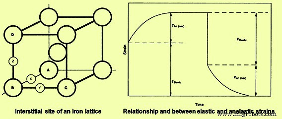
図1鉄格子と弾性および非弾性ひずみの時間依存性
弾性ひずみと非弾性ひずみの組み合わせにより、引張試験中に決定されたヤング率は、荷重速度(またはひずみ速度)に依存し、周期的または振動荷重を受ける材料に減衰または内部摩擦を生じさせる可能性があります。非弾性ひずみは、試験サンプルが固定変位でロードおよび保持されている場合の引張試験中の応力緩和の原因の1つです。この応力緩和は「弾性後遺症」と呼ばれることが多く、原子が優先サイトに移動して非弾性変形が発生すると、固定変位を維持するために必要な荷重が減少するため、時間依存の荷重降下が原因で発生します。この弾力性のある後遺症は、テスト結果に対する時間または負荷率の重要性を示しています。
試験サンプルへの引張荷重の適用に伴う総可逆ひずみは、弾性ひずみと非弾性ひずみの合計です。荷重を急速に加えると、非弾性ひずみがゼロに近づきます(非弾性ひずみにはテスト時間が十分ではありません)。したがって、荷重中の総ひずみは真の弾性ひずみに等しくなります。同じ荷重を非常にゆっくりと加えると、非弾性ひずみが荷重プロセスに伴うことができるため、このテストでの総可逆ひずみは、急速荷重中の可逆ひずみを超えます。低ひずみ速度試験でのヤング率の測定値は、高ひずみ速度試験で測定された値よりも低いため、測定された弾性係数はひずみ速度に依存します。ヤング率の低い値は「緩和弾性率」と呼ばれ、高いひずみ速度で測定された弾性率は「非緩和弾性率」と呼ばれます。
減衰能力
引張試験および繰り返し荷重は、完全に弛緩した挙動に必要なものと完全に弛緩していない挙動に必要なものの中間のひずみまたは荷重速度で行われることがよくあります。したがって、荷重または除荷のいずれかで、応力-ひずみ曲線の初期または短時間の部分は緩和されていない動作を生成しますが、曲線のその後のより長い時間の部分はより緩和された動作を生成します。緩和されていない動作から緩和された動作への移行により、応力-ひずみ曲線に荷重-除荷ヒステリシスが生成されます。このヒステリシスは、ロード-アンロードサイクル中のエネルギー損失を表します。エネルギー損失の量は、ヒステリシスの大きさに比例します。材料格子内の非弾性効果に起因する可能性のあるこのようなエネルギー損失は、「内部摩擦」と呼ばれます。内部摩擦は、鉄鋼材料が振動エネルギーを吸収する能力において重要な役割を果たします。このような吸収により、ロード/アンロードサイクル中に材料の温度が上昇する可能性があります。内部摩擦に対する材料の感受性の1つの測定値は、減衰能力です。
非弾性と内部摩擦は時間と温度に依存するため、材料の減衰能力は温度とひずみ速度の両方に依存します。内部摩擦と減衰は、振動に対する材料の応答において重要な役割を果たします。積み降ろしサイクル中に大きな内部摩擦を引き起こす条件下でテストされた鉄鋼材料は、大きなエネルギー損失を受け、高い減衰能力を持っていると言われています。これらの材料は、振動の吸収に役立ちます。例としては、非常に高い減衰能力を持ち、地域の振動から隔離される機器や機器のベースに定期的に使用されているねずみ鋳鉄があります。ミルスタンド、旋盤、プレスなどは通常、床や周辺への機械の振動の伝達を減らすために鋳鉄ベースを使用しています。ただし、高い減衰能力が必ずしも有用な材料品質であるとは限りません。
鉄鋼材料の非弾性、減衰、応力緩和、および弾性率も、材料の微細構造と試験条件に依存します。これらの特性は通常、引張試験技術では決定されません。ただし、これらのプロパティとマシンパラメータは、応力-ひずみ曲線の形状に影響を与えます。
比例制限
引張応力-ひずみ関係で曲率の開始を生成するために必要な見かけの応力は、比例限界(PL)です。 PLは、ひずみが応力に方向的に比例したままになる最大応力として定義されます。比例からの逸脱は、非弾性および/または塑性変形の開始に起因する可能性があります。引張試験中にこれらの現象の発生を検出する能力は、応力とひずみが測定される精度に依存します。 PLの測定値は、測定精度が高くなるにつれて低下します。 PLの測定値は試験精度に依存するため、PLは一般に材料の引張特性として報告されません。また、PLの価値は、エンジニアリングアプリケーションの材料の選択、認定、および使用においてほとんどまたはまったく有用ではありません。はるかに再現性が高く実用的なストレスは、材料のYSです。
材料の降伏と可塑性の開始
鉄鋼材料のYSは、材料が応力とひずみの比例関係から特定の偏差を示す応力として定義できます。比例からの非常に小さな逸脱は、非弾性効果によって引き起こされる可能性がありますが、この線形動作からの逸脱は完全に可逆的であり、重大な塑性(不可逆)変形または降伏の開始を表すものではありません。 YSの理論値は、式YS =E / 2pから計算されます。ここで、Eは弾性係数、pはPi(3.14159)の値です。理論的には、加えられた応力が弾性係数のかなりの部分でない限り、降伏は起こりません。降伏のこの推定値は、鉄鋼材料の場合、測定されたYSを少なくとも150倍予測します。理論上のYSと実際のYSの不一致は、転位の動きによるものです。転位は結晶格子の欠陥であり、これらの欠陥の動きは塑性変形の主要なメカニズムです。材料のYSを変更する手法は、転位の動きのしやすさを変更するための欠陥の相互作用に依存しています。
転位の移動度は、合金の含有量、冷間加工の程度、介在物と第2相粒子のサイズ、形状、分布、および材料の結晶粒径に依存します。合金(または不純物)原子が転位と相互作用し、その後の運動を妨げるため、合金含有量が増加するにつれて強度が増加します。したがって、このタイプの強化は、点欠陥と線欠陥の相互作用に起因します。
冷間加工は、鉄鋼材料の強度を高めるための効果的な手法です。この強化メカニズムは、冷間加工の割合が増加するにつれて材料の転位の数が増加するため、効果的です。これらの追加の転位は、他の転位の継続的な動きを制限します。冷間加工は、結晶格子内の他の線欠陥と相互作用する線欠陥による強化の例です。必要な冷間加工を提供するために、圧延、スタンピング、鍛造、絞り、スエージング、さらには押し出しを使用できます。
粒子と相境界も転位運動をブロックします。したがって、粒界の数が増加するにつれて、および/または構造の第2相のパーセンテージが増加するにつれて、YSは増加する。結晶粒径が小さくなると、単位体積あたりの粒界の数が増えるため、材料格子の面密度が増加します。領域欠陥と線欠陥の間の相互作用が転位の移動度を制限するため、結晶粒径が小さくなり、第2相粒子の数が増えるとYSが増加します。
鉄鋼材料は、強化メカニズムが異なるため、幅広いYSを示します。 YSの範囲は、粒子サイズ、冷間加工の割合、第2相粒子の分布、およびその他の比較的簡単に定量化できる微細構造パラメーターに依存します。微細構造パラメータの値は、材料の熱機械的履歴に依存します。したがって、重要な冶金学的変数の知識は、YSデータのインテリジェントな解釈、およびこれらの材料から作られた構造とコンポーネントの設計と利用のためにほとんど必要です。
YSの最も一般的な定義は、0.002 mm/mmの塑性ひずみを引き起こすのに必要な応力です。このひずみは、比例からの容易に測定可能な偏差を表し、この偏差を生成するために必要な応力は、0.2%オフセットYSです。線形挙動から0.2%の偏差に達するには、かなりの量の転位運動が必要です。したがって、標準的な引張試験では、0.2%のオフセット降伏強度は、試験機の変数、グリップ効果、および非弾性などの可逆的な非線形ひずみとはほとんど無関係です。この独立性により、0.2%のオフセット降伏強度は、鉄鋼材料の機械的特性の説明に使用される再現可能な特性です。それでも、YSの大きさ、またはその他の引張特性は、テストする材料の欠陥構造に依存することを知っておくことが重要です。したがって、YSを意味のある設計パラメータとして使用する場合は、材料の熱機械的履歴を知る必要があります。
降伏点
一部の鉄鋼材料、主に室温でテストされた低C鋼の転位運動の開始は、比較的緩やかなプロセスではなく、突然です。この突然の降伏の発生は、0.2%オフセット法による降伏の表現を非現実的にします。突然の降伏により、軟鋼の応力-ひずみ曲線には降伏点(YP)があり、軟鋼のYSはより低い降伏応力で表されます。 YPは、溶質(溶解)原子と溶媒(ホスト)格子内の転位の相互作用により発生します。軟鋼における溶質-転位相互作用には、転位へのCの移動と転位との相互作用が含まれます。相互作用により転位付近の溶質濃度が高くなるため、転位へのCの偏析によりYP点が発達すると言われています。
転位の周りの間質サイトの多くは拡大されており、したがって、溶質原子による占有のための低エネルギーまたは好ましいサイトです。これらの拡大されたサイトが占有されると、高濃度または溶質の雰囲気が転位に関連します。軟鋼では、溶質の偏析により、転位にCが豊富な雰囲気が生じます。転位の運動は、C雰囲気から転位を分離する必要があるため、制限されます。分離が起こるとすぐに、継続的な転位運動に必要な応力が減少し、引張試験では、より低いYSに到達します。この降伏プロセスには、試験サンプルの局所領域での転位運動が含まれます。転位運動は塑性変形であるため、転位が移動した領域は、材料の変形領域またはバンドを表します。これらの局所化された変形したバンドは、Lu¨dersバンドと呼ばれます。開始されると、追加のひずみにより、Lu¨dersバンドがテストサンプルのゲージ長全体に伝播します。
この伝播は、鋼の低いYSである一定の応力で発生します。ゲージセクション全体が降伏すると、転位と他の転位との相互作用のために応力-ひずみ曲線が上昇し始め、ひずみ硬化が始まります。 YPとLu¨dersバンドの存在は、処理技術に対する突然の軟化と局所的なひずみの影響のために重要です。一例として、突然の局所的な降伏は、材料のぎくしゃくした流れを引き起こします。延伸装置の負荷が急速に変化し、処理装置によって吸収されるエネルギーの大量放出を引き起こすため、延伸操作においてぎくしゃくした物質の流れは望ましくない。また、ローカライズされたLu¨ders株は、スタンピングプロセス中に材料にストレッチマークを生成します。これらのストレッチマークは「ストレッチャーひずみ」と呼ばれ、刻印された表面にすぐに現れます。これにより、表面の外観が劣化し、コンポーネントの有用性が低下します。 YPを含まない材料にスタンプを付けると、ひずみ硬化プロセスによって変形が材料全体に均一に広がるため、滑らかな表面が形成されます。
歩留まりに対する粒径の影響
構造用途で使用される鉄鋼材料は多結晶です。これらの材料には通常、多数の微細な結晶または粒子が含まれています。粒子の3次元形状は非常に複雑であるため、粒子のサイズを正確に定義することは困難です。粒子が球形であると想定される場合、粒子の直径(d)を使用してサイズを指定できます。粒子サイズをより正確に指定するために、通常、平均粒子切片(I)、および結晶粒界表面と粒子体積の比率(Sv)が含まれます。これらの2つのパラメータは、定量的金属組織学的手法によって確立できます。
ただし、歴史的な理由から、パラメータdは、鉄鋼材料のYSに対する結晶粒径の影響を説明するために使用される最も一般的な尺度です。この影響は、多くの場合、ホールペッチ関係によって定量化されます。これにより、YSは実験式によって粒子サイズに関連付けられます。
粒界は転位運動に対する障壁として機能し、転位が境界の後ろに堆積する原因となります。この転位のパイルアップは、パイルアップの先端に応力を集中させ、応力が十分である場合、追加の転位が隣接する粒子に核形成される可能性があります。転位パイルアップの先端の応力の大きさは、パイルアップ内の転位の数に依存します。パイルアップに含まれる転位の数は、粒子の体積が大きいため、粒子サイズが大きくなるにつれて増加します。パイルアップ内の転位の数のこの違いは、同等の純度の細粒材料よりも大きな粒子材料で新しい転位の核形成を容易にし、転位核形成の容易さのこの違いは、YSの違いに直接外挿します。 。
冷間加工とひずみ硬化の効果
再結晶温度より高い温度での鉄鋼材料の塑性変形は熱間加工であり、再結晶温度より低い温度でのこれらの材料の塑性変形は冷間加工である。再結晶温度を超える引張試験中のこれらの材料は、有意なひずみ硬化を示さず、引張YSは、材料が効果的にサポートできる最大応力になります。これらの材料の応力-ひずみ曲線は、引張ひずみが増加するにつれて、継続的な塑性変形を引き起こすために必要な応力が増加することを示しています。
継続的な変形に必要な応力は、特定の引張ひずみでの流動応力として指定されることがよくあります。ひずみの増加に伴う流動応力の増加は、冷間加工によって材料の強度を高めるための基礎です。材料の強度に対する結晶粒径の影響は、冷間加工プロセス全体を通して保持されます。強度の結晶粒度依存性がひずみ硬化プロセス全体で保持されるという事実は、これらの材料のさまざまな強化メカニズム間の相互作用の可能性を確立します。一例として、冷間加工は点欠陥と転位の相互作用により強度を増加させ、これらの効果は合金化の効果に追加されます。
また、冷間加工プロセスの影響を受ける引張特性は強度だけではありません。冷間加工の増加に伴い延性が低下し、冷間加工が広すぎると、冷間加工中に棒鋼にひび割れや破損が生じる可能性があります。強度と延性に対する冷間加工の全体的な効果は、強度の増加と延性の減少により、応力-ひずみ曲線の下の領域が減少することです。この領域は棒鋼を破壊するために必要な仕事またはエネルギーを表すため、これは重要です。引張試験の結果は、冷間加工の割合が増えるにつれてこのエネルギーが減少することを示しています。
冷間加工は、圧延、絞り、スタンピング、鍛造のいずれによっても、微細構造を変化させます。結果として生じる粒子形状は、処理中の金属の流れの方向によって決まります。冷間圧延したサンプルの結晶粒は細長く平らになっているため、半球形の結晶粒からパンケーキ型の結晶粒に変化します。ロッドドローイングプロセスは、針状の粒子を生成します。結晶粒の形状の変化に加えて、冷間加工操作によって結晶粒の内部が歪んでいます。転位密度の高い帯(変形帯)が発達し、双晶界が曲がり、粒界が粗く歪む。微細構造の変形による変化は異方性であるため、鍛鋼材料の引張特性は異方性であることがよくあります。冷間加工から生じるひずみ硬化微細構造および付随する機械的特性は、焼きなましによって大幅に変更することができます。より高い温度に加熱することによって導入される微細構造の変化は、アニーリングの時間と温度の両方に依存します。この温度依存性は、アニーリングを効果的にするために原子の動きが必要なために生じます。
引張強度
ひずみ硬化する能力は、鉄鋼材料を他のエンジニアリング材料から分離する機械的挙動の通常の特性の1つです。すべての金属材料がこの特性を示すわけではありません。一例として、クロム(Cr)は非常に脆く、引張試験で破壊しますが、ひずみ硬化の形跡はありません。脆性材料の応力-ひずみ曲線は、セラミック材料の応力-ひずみ曲線と似ています。破壊は、大きな塑性変形が発生する前に発生します。このような脆性材料には実際のYSがなく、破壊応力は材料がサポートできる最大応力です。ただし、鉄鋼材料は破壊前に塑性変形し、材料がサポートできる最大応力はYSよりもかなり高くなります。この最大応力(元の寸法に基づく)は、材料の極限強度または引張強度(TS)です。
YSとTSの間のマージンは、構造物の鉄鋼材料の操作上の安全率を提供します。この安全マージンを除けば、TSの実際の値はほとんど実用的ではありません。複雑なサービス負荷に耐える構造の能力は、TSとはほとんど関係がなく、構造設計は降伏に基づく必要があります。 TSは測定が簡単で、応力-ひずみ曲線の最大応力であるため、頻繁に報告されます。エンジニアリングコードでは、材料が特定のTS要件を満たすように指定されている場合があります。
歴史的に、TSは、歩留まりを回避するために経験に基づいた削減を行い、設計計算に使用されていました。応力-ひずみ曲線の測定精度が向上するにつれて、TSの使用率が低下し、1940年代までに、いくつかの設計コードは降伏に基づいていました。 TSを硬度、疲労強度(FS)、応力破壊、および機械的特性と相関させる大規模な経験的データベースがあります。これらの相関関係、過去のコード要件、および脆性材料を組み込んだ構造設計がTSに基づくという事実は、設計基準としてTSを継続的に利用するための技術的基盤を提供します。
鉄鋼材料の冷間加工およびその他の強化メカニズムは、YSを増加させるほど急速にTSを増加させません。したがって、強化プロセスには、塑性ひずみを受ける能力の低下が伴うことがよくあります。この減少は、破壊前にエネルギーを吸収する材料の能力を低下させ、多くの場合、これらの材料の利用を成功させるために重要です。これらの材料の引張挙動の分析は、材料のエネルギー吸収能力への洞察を提供することができます。
タフネス
破壊することなくエネルギーを吸収する能力は、材料の靭性によるものです。ほとんどの場合、鉄鋼材料の破壊は既存の欠陥から始まります。これらの欠陥は、微細構造の要素となるのに十分小さい場合があり、わずかに大きい場合は、材料の巨視的な亀裂、または極端な場合には、構造の視覚的に観察可能な不連続性である可能性があります。強靭な鋼材は、降伏や塑性変形などのプロセスによる欠陥の伝播に抵抗します。この変形の最大値は、欠陥の先端近くで発生します。破壊には引張応力と塑性変形またはひずみの両方が含まれるため、応力-ひずみ曲線を使用して材料の靭性を推定できます。ただし、材料の靭性を測定するために設計された特定のテストがあります。これらのテストの大部分は、事前に亀裂が入ったサンプルを使用して実施され、衝撃力学と破壊力学の両方が含まれています。引張挙動に基づく靭性の計算は推定値であり、設計には使用されません。
応力-ひずみ曲線の下の面積は、引張試験中に材料によって吸収されるエネルギーの尺度です。この領域は、材料の靭性の概算です。 Since the plastic strain associated with tensile deformation of iron and steel materials is typically several orders of magnitude greater than the accompanying elastic strain, plasticity or dislocation motion is very important to the development of toughness. This is demonstrated by the stress-strain curves for a brittle, a semi-brittle, and a ductile material. Brittle fracture takes place with little or no plastic strain, and thus the area (A) under the stress-strain curve is given by the equation A =0.5 Se. Estimation of the fracture energy from the typical tensile properties of mild steel test sample with a YS of 205 MPa, TS of 415 MPa, and strain to fracture value of 0.3, gives 1.12 J/ cu mm of gauge section of the test sample.
The ratio of the energy for ductile fracture to the energy for brittle fracture is 900. This ratio increases with increasing strain to fracture and with increasing strain hardening. The area and energy relationship is only approximate. The utility of such toughness estimates is the ease with which testing can be done and the insight that the estimates provide into the importance of plasticity to the prevention of fracture. Further, a plastic strain of only 0.01 % can have a remarkable effect on the ability of the material to absorb energy without fracturing.
Toughness is a very important property for many structural applications. Crane arms, ship hulls, axles, gears, and couplings are all required to absorb energy during service. The ability to withstand earthquake loadings, system overpressures, and even minor accidents also need material toughness. Increasing the strength of iron and steel materials usually reduces ductility and, in many cases, reduces toughness. Thus, increasing the strength of the material can increase the likelihood of service-induced failure when material toughness is important for satisfactory service.
This is seen by comparing the areas under the two stress-strain curves in Fig 2. The cross-hatched areas in Fig 2 show another tensile property which is the modulus of resilience. Modulus of resilience can be measured from tensile stress-strain curves. The ability of iron and steel materials to absorb energy through elastic process is the resilience of the material. The modulus of resilience is defined as the area under the elastic portion of the stress-strain curve. Increasing the YS and/or decreasing Young’s modulus increase the modulus of resilience and improve the ability of these materials to absorb energy without undergoing permanent deformation.
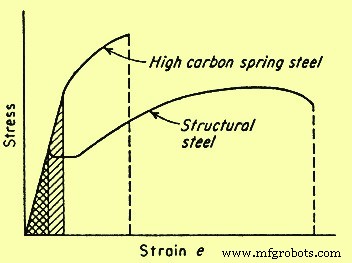
Fig 2 Comparison of the stress-strain curves for high and low toughness steels
Material ductility
Material ductility during tensile testing is generally established by measuring either the elongation to fracture or the reduction in area (RA) at fracture. In general, measurement of ductility is of interest in three ways namely (i) to indicate the extent to which a steel can be deformed without fracture in metalworking operations such as rolling, forming, or extrusion, (ii) to indicate to the designer, in a general way, the ability of the steel to flow plastically before fracture, and (iii) to serve as an indicator of changes in impurity level or processing conditions. Ductility measurement is to be specified to assess material quality even though no direct relationship exists between the ductility measurement and the performance.
Tensile ductility is a very useful measure during the assessment of material quality. Many codes and standards specify minimum values for tensile ductility. One reason for these specifications is the assurance of adequate toughness without the necessity of requiring a more costly toughness specification. Most changes in material composition and/or processing conditions produce changes in tensile ductility. Further, the metal-working features of iron and steel materials are better correlated with the ability to strain harden than with the ductility of the material. The strain-hardening abilities of many iron and steel materials used for engineering service have been quantified through the analysis of true stress-strain behaviour.
True stress-strain relationship
Conversion of engineering stress-strain behaviour to true stress-strain relationship shows that the maximum in the engineering stress-strain curve results from tensile instability, not from a decrease in the strength of the material. The drop in the engineering stress-strain curve is artificial and occurs only because stress calculation is based on the original cross-sectional area. Both testing and analysis show that, for most iron and steel materials, the tensile instability corresponds to the onset of necking in the test specimen. Necking results from strain localization. Hence, once necking is initiated, true strain cannot be calculated from sample elongation. Due to these and other analytical limitations of engineering stress-strain data, if tensile data is used to understand and predict metallurgical response during the deformation associated with fabrication processes, then true stress-true strain relationship is favoured.
The deformation which can be accommodated without fracture in a deep drawing operation varies with the material. As an example, austenitic stainless steel can be successfully drawn to 50 % RA whereas ferritic steel may fail after around 20 % to 30 % RA in similar drawing operations. Both types of steels undergo in excess of 50 % RA during tensile testing. This difference in drawability correlates with the strain-hardening exponent (n) and therefore is apparent from the slope of the true stress-strain curves for the two steels.
The n values for ferritic and austenitic steels are typically 0.25 and 0.5 respectively. A perfectly plastic material has a n value of zero and a completely elastic solid has a n value of one. Most iron and steel materials have n values between 0.1 and 0.5. Strain-hardening exponents correlate with the ability of dislocations to move around or over dislocations and other obstacles in their path. Such movement is termed ‘cross slip’. When cross slip is easy, dislocations do not pile up behind each other and n value is low. Mild steel is the example which undergoes cross slip easily. The n value increases as cross slip becomes more difficult. Cross slip is very difficult in austenitic stainless steel and the n value for this steel is around 0.5.
Tensile samples, sheets, plates, wires, rods, and other metallic sections have spot-to-spot variations in section size, YS, and other microstructural and structural in-homogeneities. Plastic deformation of these materials initiates at the locally weak regions. In the absence of strain hardening, this initial plastic strain reduces the net section size and focuses continued deformation in the weak areas. However, strain hardening causes the flow stress in the deformed region to increase. This increase in flow stress increases the load necessary for continued plastic deformation in the area and causes the deformation to spread throughout the section. The higher the n value, the greater is the increase in low stress and the greater is the tendency for plastic deformation to become uniform. This tendency has a major impact on the fabricability of the iron and steel materials.
As an example, the maximum RA which can be accommodated in a drawing operation is equal to the n value as determined from the true stress-strain behaviour of the material. Because of such correlation, the effect of process variables such as strain rate and temperature can be evaluated through tensile testing. This provides a basis to estimate the effect of process variables without direct, in-process assessment of the variables.
Temperature and strain rate effects
The YS of most iron and steel materials increases as the strain rate increases and decreases as the temperature increases. This dependence results from a combination of several metallurgical factors. As an example, dislocations are actually displacements and hence cannot move faster than the speed of sound. Also, as dislocation velocities approach the speed of sound, cross slip becomes increasingly difficult and the n value increases. This increase in the n value increases the flow stress at any given strain, thus increasing the YS of the material. A decrease in ductility and even a transition from ductile to brittle fracture can also be associated with strain rate induced increases in the YS.
In many respects, decreasing the temperature is similar to increasing the strain rate. The mobility of dislocations decreases as the temperature decreases, and hence for most of the iron and steel materials, the strength increases and the ductility decreases as the temperatures are lowered. If the reduction in dislocation mobility is adequate, the ductility can be reduced to the point of brittle fracture. Iron and steel materials which show a transition from ductile to brittle fracture when the temperature is lowered are not to be used for structural application at temperature which is below this transition temperature.
Dislocation motion is inhibited by interaction between dislocation and by the alloying or impurity (alien) atom. The effect of this interaction is both time and temperature dependent. The interaction acts to increase the YS and limit ductility. The process is most effective when there is enough time for alien atom to segregate to the dislocation and when dislocation velocity is almost equal to the diffusion velocity of the alien atom. Hence, at any given temperature, dislocation- alien atom interaction is at a maximum at some intermediate strain rate. At low strain rate, the alien atom can diffuse as rapidly as the dislocation moves and there is little or no tendency for the deformation process to force a separation of dislocation from its solute atmosphere. At high strain rates, once separation has been achieved, there is no adequate time available for the atmosphere to be re-established during the testing period. Atom movement increases with increasing temperature, thus the strain rate which allows dislocation-alien atom interaction to occur is temperature dependent. Since this interaction limits ductility, the elongation in tensile testing can show a minimum at intermediate test temperature where such interaction is very effective.
The effect of time dependent dislocation-alien atom interaction on the stress-strain curve of iron and steel materials is termed as ‘strain aging’ and ‘dynamic strain aging’. Strain aging is usually apparent when tensile testing of the material which shows a sharp YP, is interrupted. If the testing sample is unloaded after being strained past the YP, through the Lu¨ders strain region and into the strain-hardening portion of the stress-strain curve, either of two behaviours are observed when the tensile test is resumed.
If the sample is reloaded in a short period of time, the elastic portion of the reloading curve is parallel to the original elastic loading curve and plastic deformation resumes at the stress level which was reached just before the testing was interrupted. However, if the time between unloading and reloading is enough for segregation of alien atom to the dislocation, the YP reappears and plastic strain is not reinitiated when the unloading stress level is reached. This reappearance of the YP is strain aging, and the strength of the strain aging peak is dependent on both time and temperature since solute-atom diffusion and segregation to dislocation is needed for the peak to develop. If tensile strain rate is in a range where solute segregation can occur during the testing, dynamic strain aging is observed. Segregation pins the previously mobile dislocation and increases the flow stress, and when the new, higher flow stress is reached the dislocation is separated from the solute atmosphere and the flow stress decreases. This alternate increase and decrease in flow stress causes the stress-strain curve to be serrated.
Serrated flow is usual in mild steel since it contains mobile, alloy or impurity element. This effect has been initially studied in detail by Portevin and LeChatelier and is often called the Portevin-LeChatelier effect. Processing condition is to be selected to avoid strain aging effect. This selection essentially involves the control of processing strain rate and temperature.
Special testing methods
The tensile test provides basic information concerning the response of iron and steel materials to mechanical loading. Testing temperature and strain rate (or loading rate) normally is controlled due to the effects of these variables on the metallurgical response of the sample. The tensile testing usually measures strength and ductility. These parameters are frequently sensitive to the sample configuration, testing environment, and the manner in which the testing is conducted. Special tensile testing methods have been developed to measure the effect of testing/sample conditions on the strength and ductility of iron and steel materials. These testing methods include the notch tensile test and the slow-strain-rate tensile test.
Notch tensile testing
Iron and steel materials used in engineering applications is often required to withstand multi-axial loading and high stress concentration because of component configuration. Standard tensile testing measures material performance in a smooth bar sample exposed to uniaxial load. This difference between application and testing sample can reduce the ability of the standard tensile testing to predict material response under anticipated condition of application. Also, the reduction in ductility usually induced by multi-axial loading and stress concentration may not be visible in the testing result. The notched tensile testing therefore has been developed to minimize this weakness in the standard tensile testing and to examine the behaviour of material in the presence of flaws, notches, and stress concentrations.
The notched tensile sample usually contains a 60 deg notch which has a root radius of less than 0.025 mm. The stress state just below the notch tip approaches tri-axial tension, and for ductile steels this stress state normally increases the YS and decreases the ductility. This increase in YS results from the effect of stress state on dislocation dynamics. Shear stress is needed for the dislocation motion. Pure tri-axial loading does not produce any shear stress. Hence, dislocation motion at the notch tip is limited and the YS value is increased. This constraint in dislocation motion also reduces the ductility of the notched sample. For low ductility steels, the notch-induced reduction in ductility can be so severe that failure takes place before the 0.2 % offset YS is reached.
The sensitivity of iron and steel materials to notch effect is termed as the ‘notch sensitivity’. This sensitivity is quantified through the ratio of notch strength to smooth bar TS. Material which is notch sensitive has ratio less than one. Smooth bar tensile data for these materials does not satisfactory predicts the material behaviour under service conditions. Tough ductile material often is notch-strengthened and has notch sensitivity ratio greater than one, thus the standard tensile testing is a conservative predictor of performance for this material.
Slow strain rate testing
Testing environments can also have adverse effects on the tensile behaviour of iron and steel materials. The characterization of environmental effect on material response can be accomplished by conducting the tensile testing in the environment of interest. Since the severity of environmental attack usually increases with increasing time, tensile testing designed to determine environmental effects often is conducted at very low strain rate. The low strain rate increases the testing time and maximizes exposure to the testing environment. This type of testing is termed either ‘slow strain rate testing’ (SSRT) or ‘constant extension rate testing’ (CERT). Exposure to the aggressive environment can reduce the strength and/or ductility of the testing sample. This reduction can be accompanied by the onset of surface cracking and/or a change in the fracture mode. SSRT or CERT study which displays harmful effects on the tensile behaviour, establishes that the test material is susceptible to environmental degradation.
This susceptibility can cause concern over the utilization of the material in that environment. Conversely, the test can show that the tensile behaviour of the material is not influenced by the environment and is therefore suitable for application in that environment. SSRT or CERT can be used to screen materials for potential service exposures and/or examine the effects of anticipated operational changes on the materials used in process systems. In either case, the intent is to avoid materials utilization under conditions which may degrade the strength and ductility and cause premature failure. In addition to the tensile data, evidence of adverse environmental effect can also be found through examination of the fracture morphology of the testing samples of CERT and SSRT.
Fracture characteristics
Tensile fracture of ductile iron and steel materials generally initiates internally in the necked portion of the tensile bar. Particles such as inclusion, dispersed second phase, and/or precipitate can serve as the nucleation sites. The fracture process begins by the development of small hole, or micro-void, at the particle-matrix interface. Continued deformation enlarges the micro-void until, at some point in the testing process, the micro-void contacts other micro-void and coalesces. This process is termed ‘micro-void coalescence’ and gives rise to the dimpled fracture surface topography characteristic of the ductile failure processes.
The surface topography of a brittle fracture differs significantly from that of micro-void coalescence. Brittle fracture generally initiates at imperfections on the external surface of the material and propagates either by trans-granular cleavage like process or by separation along grain boundary. The resultant surface topography is either faceted, perhaps with the river like pattern typical of cleavage, or inter- granular, producing a ‘rock candy’ like appearance. The testing material can be inherently brittle or brittleness can be introduced by heat treatment, lowering of the testing temperature, the presence of an aggressive environment, and/or the presence of a sharp notch on the testing sample.
The temperature, strain rate, test environment, and other conditions, including sample surface finish for tensile testing, are generally well established. An understanding of the effects of such testing parameters on the fracture characteristics of the test sample can be very useful in the determination of the susceptibility of iron and steel materials for degradation during the fabrication or during the application. Typically, any heat treatment or testing condition which causes the fracture process to change from micro-void coalescence to a more brittle fracture mode reduces the ductility and toughness of the material and can promote early fracture under selected service conditions. Since the fracture process is very sensitive to both the metallurgical condition of the sample and the conditions of the tensile testing, characterization of the fracture surface is an important component of many tensile-testing programs.
製造プロセス