


炭素鋼と低合金鋼の溶接および水素誘起割れ
炭素鋼と低合金鋼の溶接および水素誘起割れ
アーク溶接は、鋼が合体して接合されるプロセスです。通常、このプロセスでは互換性のあるフィラー材料を使用します。良好に接合された接合部を作成する前に、溶接金属と完全に融合するために、接合部の表面を溶融温度以上に加熱する必要があります。溶融、凝固、および固体変態を伴う冶金反応は珍しいことではありませんが、観察される温度と冷却速度は厳しいものです。
活性ガスも存在し、溶鋼に溶解する可能性があります。フラックスは、溶接金属と合金化して保護するために導入されます。一般に、ジョイントは剛性があり、収縮とソリッドステート変換によって引き起こされる寸法変化を抑制し、降伏強度(YS)の大きさの残留応力を生成します。冶金学的変化は平衡状態では発生せず、応力が高いため、反応の多くは溶接金属と鋼の熱影響部(HAZ)のいずれかまたは両方で発生し、欠陥を生成してそれらを弱める可能性があります。健全性。
溶接プロセスには大きなばらつきがあるため、関連する正確なメカニズムや実行可能な修正について詳細を提供することは困難です。さらに、ほとんどの欠陥が説明されると、多くの修正措置が明らかになります。水素(H2)に関連する1つの問題は、単純ではありません。この問題は、より高強度、低合金(HSLA)の鋼が溶接されるにつれてより関連性が高くなるため、水素誘起割れ(HIC)の問題は非常に重要です。
炭素鋼(C)と低合金鋼は、幅広い用途と優れた溶接性を備えているため、溶接されます。この有用性は、主に鉄(Fe)ベースシステムの冶金学的特性によるものです。この特性には、多数の元素と容易に合金化できる能力に加えて、マルテンサイトおよびベイナイト変態または析出メカニズムによって硬化および強化の機会を可能にする同素体(微細構造)変態を起こす能力が含まれます。 C鋼および低合金鋼の溶接性は、一般に(i)製造溶接性と(ii)サービス溶接性に分類できます。
製造溶接性は、有害な不連続性を導入することなく、溶接によってC鋼と低合金鋼を接合できるためです。これらの不連続性の許容範囲は、特定の溶接部の適用条件によって異なります。鋼の製造溶接性は、重要ではない用途に適している可能性があります。ただし、同じ鋼が重要な用途に推奨されない場合や、溶接時に予熱などの特別な予防措置が必要になる場合があります。製造溶接性は、主にH2支援多孔性、ラメラ引き裂き、コールドクラッキング、ホットクラッキング、再熱クラッキングなどの不連続性を扱います。
C鋼および低合金鋼の使用溶接性は、完成した溶接物が目的の機能を果たすのに十分な特性を備えているという事実によるものです。サービス溶接性の重要な特徴は、HAZ特性と影響を受けていないベース鋼の特性との比較です。サービス溶接性の許容性は、計画されているアプリケーションにも依存します。特定の鋼の使用溶接性は、腐食が非常に重要であるが靭性が二次的に重要である用途では許容できる場合があります。ただし、同じ鋼は、靭性が非常に重要な用途には受け入れられません。サービス溶接性には、HAZの特性に対する溶接熱サイクルの影響が含まれます。使用溶接性は、特定の鋼に許容される入熱の範囲を決定することがよくあります。低入熱は、望ましくない低靭性の微細構造、およびコールドクラックに関連する製造溶接性の問題を引き起こす可能性があります。高入熱は、低靭性と低強度の両方を備えた粗い微細構造を導入する可能性があります。入熱だけでは、結果として生じる微細構造とHAZ特性は制御されませんが、誘導される熱サイクルは微細構造と特性を制御します。したがって、入熱と鋼の厚さの両方が重要です。
鋼の分類
C鋼と低合金鋼は、さまざまな組成と特性をカバーしています。鋼は、Cおよび/または合金元素の含有量に従って分類されることがよくあります。プレーンC鋼、C-Mn(マンガン)鋼、中C鋼、低合金鋼、高強度低合金(HSLA)鋼、マイクロアロイド鋼など、さまざまな名称でさまざまな分類が利用できます。最近、鋼の新しい分類により、分類要素として鋼加工法が導入されました。さまざまな呼称で知られているこれらの鋼は、熱機械制御処理(TMCP)鋼と呼ばれることがよくあります。上記のすべての分類間の境界は、しばしば拡散し、しばしば重複し、時には主観的です。
低C鋼には、最大約0.30%のCと最大約1.65%のMnが含まれています。溶接用途に使用される圧延鋼のほとんどは、低C鋼で構成されています。このグループには、溶接性に大きなばらつきがある鋼が含まれます。一例として、すべての溶接プロセスで0.15%C未満の低C鋼を溶接することが可能です。 0.15%から0.30%Cを含む低C鋼(通常は軟鋼として知られています)を最大25mmの厚さで溶接することも可能です。ただし、軟鋼の厚い部分では、溶接を成功させるために追加のアクションが必要になる場合があります。
HSLA鋼は、従来のC鋼よりも優れた機械的特性を提供するように設計されています。この鋼は通常、YSが290〜550 N / sq mmで、C-Mnタイプであり、結晶粒の微細化と析出硬化を確実にするために、ニオブ(Nb)とバナジウム(V)が非常に少量添加されています。 HSLA鋼は通常、マイクロアロイド鋼として識別されます。この鋼は通常、圧延時または正規化された状態で溶接されます。 HSLA鋼の溶接性は、軟鋼の溶接性と同様です。
最近、低C、銅(Cu)を含む老化硬化性のHSLA鋼の新しいファミリーが開発されました。 Cu、Ni(ニッケル)、およびCr(クロム)の総含有量は通常1%に近いため、これらの鋼は真に低合金ではありません。これらの鋼の溶接性は、主にC含有量が低い(0.06%未満)ため、非常に良好です。これらの鋼は、一般的に焼入れおよび時効状態で使用されています。これらの2つの条件のために、これらの鋼はTMCP鋼としても特徴付けられることがあります。焼入れ焼戻し(Q&T)鋼は、YSが350〜1030 N /sqmmになるように熱処理されています。これらの鋼の他の例には、Ni-Cr-Mo(モリブデン)鋼が含まれます。これらの鋼の溶接部は、いくつかの特別な用途での溶接後熱処理(応力緩和)を除いて、一般にそれ以上の熱処理を必要としません。選択された急冷および焼き戻し鋼に対するこれらのHSLA鋼の利点は、Cuの時効硬化に必要な溶接予熱が少ないことです。ただし、これらのHSLA鋼は軟鋼のように溶接されません。
熱処理可能な低合金(HTLA)鋼は通常、再オーステナイト化され、溶接後に焼入れおよび焼き戻しされます。この鋼は比較的焼入れ鋼であり、焼入れ焼入れ状態で960 N /sqmmより高いYSを発生します。溶接金属は通常、溶接されたままの状態または応力が緩和された状態では、このレベルで強度と靭性の許容可能な組み合わせを開発することはできません。したがって、再オーステナイト化してから、溶接後に溶接部全体を急冷および焼き戻しする必要があります。
TMCP鋼は一般に、制御された圧延とそれに続く加速冷却またはインライン直接焼入れの組み合わせで製造されます。この加工により、良好な溶接性を維持しながら、高強度と高靭性の組み合わせを開発することができます。これらの鋼の合金元素の含有量は非常に低く保つことができ、C含有量は通常0.06%未満であるため、溶接性は良好です。これらの鋼では、700 N /sqmm以上のYSレベルが可能です。これらの鋼は通常、予熱なしで溶接できます。ただし、高強度レベルでは、溶接金属の亀裂を防ぐために予熱が必要になる場合があります。
Cr-Mo鋼は高温用途に広く使用されています。これらの鋼のCr含有量は0.5%から9%まで変化し、Mo含有量は0.5%から1.0%まで変化します。これらの鋼は通常、「正規化および焼き戻し」または「焼き入れおよび焼き戻し」状態で出荷されます。これらの鋼は適度な焼入れ性を備えているため、H2アシストコールドクラッキング(HACC)を回避するために適切な予防措置が必要です。サービスアプリケーションでは、これらの鋼の溶接に追加の要件が課されることがよくあります。一例として、一部の業界では、これらの鋼は耐クリープ性のために必要であり、溶接金属とHAZの両方が適切なクリープ特性を提供する必要があります。一部の業界の腐食雰囲気では、腐食割れを防ぐために最大HAZ硬度を制限する必要があります。
HACCに対する鋼の相対的な感受性
Gravilleは、HACCに対する感受性は、C等価物(CE)を計算し、Graville図(図1)に示すようにC含有量と比較することで評価できることを示唆しています。ゾーンIの下の鋼は、Cが低く、焼入れ性が低く、割れの影響をあまり受けません。ゾーンIIIの鋼は、高いCと高い焼入れ性の両方を備えており、すべての溶接条件で亀裂に敏感な微細構造が生成されます。したがって、ゾーンIIIの鋼でHACCを回避するには、予熱および溶接後の熱処理を含む低H2対策を使用する必要があります。ゾーンIIの鋼は、Cレベルが高く、焼入れ性が低くなります。したがって、HAZの冷却速度を制限することにより、亀裂に敏感な微細構造を回避することができます。これは、入熱を制御することで達成できますが、少しは予熱することで達成できます。
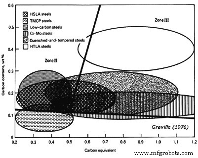 図1C含有量およびCEと比較したHACCに対する鋼の感受性を示すグラビル図
グラビル図で考慮されるCEは、CE =%C +(%Mn +%Si)/ 6 +(%Ni +%Cu)/ 15 +(%Cr +%Mo +%V)/5です。鋼がゾーンIからゾーンII、およびゾーンIIIに移動するにつれて、コールドクラックに対する感受性は徐々に増加します。グラビル図は、主にゾーンIIIにある熱処理可能な合金鋼が、溶接に関して特別な考慮を必要とすることも示しています。一部のHSLA鋼で必要とされるように、Cr-MoおよびQ&T鋼にも注意が必要です。低C鋼は、いくつかの予防措置が必要な厚い部分を除いて、容易に溶接されます。 TMCP鋼はゾーンIに位置するように特別に開発されており、そのため溶接性に優れています。図1は、溶接性の1つの側面のみを示しており、他にも多くの懸念事項があります。HACCに関して望ましいのは、組成カバーをグラビル図の左下隅に向かって押す鋼を使用することです。
アーク溶接に関連する通常の欠陥
多孔性は、ガス、特にH2とN2(窒素)の小さなポケットの閉じ込めによって引き起こされます。これらは通常、固体の鉄(Fe)よりも液体への溶解度が高くなります。凝固中、ガスは溶接金属から出ようとします。ただし、凝固速度が速いため、一部のガスが閉じ込められる可能性があります。この閉じ込めは、ガス溶解速度と溶接金属の凝固速度の両方に依存します。溶解速度が速い場合、鋼が固化する前に気泡が発生して逃げる可能性があります。速度が遅い場合、ガスは溶液中に残ります。これにより、多孔性は回避されますが、H2誘起割れ(HIC)や靭性の低下などの他の問題が発生します。中程度の速度では、ガスは核形成する可能性があり、溶接金属に溶解するガスの量と溶接凝固速度に応じて、気泡が発生し、閉じ込められます。ワームホールと呼ばれる非常に深刻な形態の多孔性は、ガスの発生と凝固の速度が同じである場合に発生し、本質的に球形の気泡の代わりに細長いガスポケットが発生します。
H2の考えられる原因には、フラックス中の水分、ワイヤ引き抜き潤滑剤中の炭化水素、または溶接される接合部の表面汚染物質、および「ガスメタルアーク溶接」(GMAW)装置での水漏れがあります。 N2は、アークのシールドが不十分な結果としてアーク領域に入る空気から収集されます。 GMAWの場合、これは、ガス流量が低すぎてクロスドラフトがシールドを変位させるか、高すぎて周囲の大気がシールドガスに吸引される場合に発生する可能性があります。 「被覆アーク溶接」(SMAW)プロセスでは、これは、溶接工が十分なスキルを持っていないか、アーク長が長すぎる原因となる不適切な方法を使用している場合に発生する可能性があります。
不完全な癒合は、不十分な関節貫通、根の癒合の欠如、または側壁の癒合の欠如など、いくつかの形態をとることがあります。これらの欠陥は、(i)溶接への不十分なエネルギー入力、主に不十分な電流、(ii)溶接金属がアークの前を流れることを可能にする過度の移動速度、または(iii)不適切な電極角度または作業位置によって引き起こされる可能性があります。
ジョイントの溶け込みとルートの融合の問題は、通常、使用されている溶接プロセスに適さないジョイントデザインの使用、またはアークの適切な溶け込みを提供するために必要な対策の無視が原因です。ほとんどの場合、これは溶接電流が低すぎることを意味します。ただし、ガスシールド溶接プロセスの場合、間違ったシールドガスが使用されている可能性があります。例として、アルゴン(Ar)が豊富なガス混合物の場合、かなり深い中央の「指」を除いて、浸透パターンは比較的浅いです。残念ながら、この指は通常中央に配置されていないため、信頼できません。ただし、ヘリウム(He)または二酸化炭素(CO2)が豊富なシールドガス混合物は、より均一でより深い有用な浸透パターンが可能です。片側からの溶接時に発生するルートフュージョンが不十分な場合は、溶け込みを良くするためにジョイントデザインを変更するか、鋼片の両側から溶接を変更する必要があります。
ほとんどの場合、溶接金属と接合部の間の側壁の融合の欠如は、適切な対策または制御技術が溶接工によって使用されていない場合に発生します。 GMAWプロセスでは、重いセクションを溶接するときに、短絡転送などの不適切なバリエーションを使用していることが原因である可能性があります。短絡伝達は低エネルギーレベルでのみ有効であるため、あらゆる位置で鋼板または薄板を溶接するのに非常に適しています。これは、プロセスがほとんど浸透せず、溶接金属をすばやく凍結するように設計されているためです。そのため、熱が急速に放出される接合部、つまり6mmより厚い接合部の側壁には溶接金属が溶着しません。 Arを使用したスプレーアークとCO2シールドデポジット溶接を使用した埋め込みアークの両方が、垂直または頭上位置でサポートするには大きすぎて流体です。ただし、これらのプロセスは、フラットまたは水平位置で溶接を行う場合に非常に効果的です。一方、Arリッチシールドによるパルスアーク変動は、すべての位置で非常に効果的であり、十分な溶け込みと溶融池の制御の両方を提供して、不十分な側壁溶融によって引き起こされる欠陥を防ぎます。
ホットクラックは、中心線または凝固亀裂とも呼ばれ、拘束された溶接の中心線に沿った低融点成分の排除によって引き起こされます。それらは、溶接が完了した直後、そして時には溶接が行われている間に発生します。溶接部が壊れてこれらの亀裂が露出した場合、それらは青くなっているか、熱着色されていることがわかります。これらの亀裂は、硫黄(S)とリン(P)によって引き起こされることが多く、高C合金鋼で発生する可能性が高くなります。ほとんどの場合、ベース鋼板がそのソースです。溶接組成に基づく亀裂の影響を受けやすさは、UCS =230 X%C + 190 X%S + 75 X%P + 45 X%Nb – 12.3 X%Si – 5.4 X%Mnなどの実験式と比較されています。 – 1.この場合、UCS値が10未満の場合、亀裂の影響を受けやすくなります。一方、30を超える値はこの影響を受けやすいことを意味し、10〜30の値は溶接技術を制御する必要があることを意味します。
溶接ビードのホットクラックやクレータークラックなどの欠陥は、高希釈(つまり、深い溶け込み)を生成する溶接プロセスまたは技術で発生する可能性が高くなります。中心線の亀裂に寄与する別の要因は、溶接クレーターの鋭いティアドロッププロファイルです。これは、高い溶接速度の特徴です。このような状況では、溶接クレーターはクレータークラックと呼ばれる収縮クラックを発生させることがよくあります。ティアドロップクレーターとディープペネトレーションはどちらも、「サブマージアーク溶接」(SAW)プロセスとCO2シールドを使用したGMAWプロセスで生成されます。この問題は、非常に凹状のすみ肉溶接でも発生する可能性があります。これは、溶接の収縮による横方向の応力に耐えるのに断面が十分でない可能性があるためです。
ほとんどの場合、SレベルとPレベルの合計を0.06%未満に保つことで、問題を防ぐことができます。ただし、高張力鋼を使用して高度に拘束された接合部を溶接する場合は、通常、0.03%未満の合計レベルが必要です。溶接する鋼に過剰な量のSまたはPが含まれている場合、(i)深く浸透しない溶接方法または技術を使用し、(ii)裂け目の形成を防ぐのに十分遅い移動速度を選択することにより、高温亀裂を回避できます。クレーターをドロップし、(iii)凸状のビードプロファイルを提供し、(iv)各ビードの端でクレーターを埋めます。
層状の裂け目は、ベース鋼板の厚さ全体に応力がかかると発生し、通常はHAZのすぐ下に見られます。これは、鋼板表面の下にある介在物の薄層を含む帯状鋼に関連しています。汚れた鋼を使用する場合は、接合部の設計を変更して、溶接部の鋼板の厚さによるひずみを最小限に抑えることで、問題を防ぐことができます。
アンダーカットは、通常、水平フィレット溶接の上部つま先に見られる不規則なガウジです。溶接のその部分の鋼製ベースプレートはアークによって溶けますが、溶接金属によって再充填されません。ほとんどの場合、この欠陥は、電極角度、移動速度、溶接電流などの不適切に選択された溶接条件が原因で発生します。長さが8mmを超える脚ですみ肉溶接を行おうとすると発生する可能性が高くなります。 GMAWプロセスでは、2%未満の酸素(O2)を含むArシールドを使用した場合にも発生する可能性があります。アンダーカットは、垂直位置で行われた溶接にも見られます。これは、通常、過度の織りに起因します。
ロールオーバーとも呼ばれるオーバーラップは、通常、すみ肉溶接に関連しており、溶接電流が低すぎてベース鋼板を適切に溶着できない場合、または移動速度が低すぎて溶着量を受け入れることができない場合に発生します。 SMAWプロセス中の電極の不適切な取り扱いも要因となる可能性があります。
介在物は、溶接パスの間に閉じ込められたスラグによって生成されます。それらは、接合部に閉じ込められる可能性のある未溶融フラックスの断片として、またはアークの前を流れて溶接によって覆われるスラグとして、または溶接パス間で除去されていない固化したスラグとして発生します。溶接前に接合部から除去されていない重いミルスケールとして。この問題は、SMAWプロセスで最も一般的です。これは、溶接機側の不十分な制御技術によって問題が悪化する可能性があるためです。介在物の存在は、高クラウン溶接または粗い溶接で溶接する場合に予想されます。これは、パス間でエッジをクリーニングしたり、溶接中に貫通したりすることが難しいためです。防止は、(i)正確なフラットプロファイルを持つ溶接を溶着するように溶接工をトレーニングすること、(ii)より高いエネルギーとより多くの流体を溶着できるように溶接を配置すること、(iii)パス間の錆の発生を防ぐこと、および(iv)によって可能です。クリーニングまたは研削のいずれかによって、パス間で溶接が適切に調整されていることを確認します。
水素によるクラッキング
水素誘起割れ(HIC)は、主に低合金鋼の溶接に関連する現象です。 HICに寄与する要因は、(i)H2の存在、(ii)高い引張応力、(iii)影響を受けやすい微細構造、(iv)約200℃から-100℃の間の温度、および(v)時間です。より低い強度レベル(約490 N / sq mm)では、HICは通常、ベース鋼のHAZの縦方向の亀裂として観察され、しばしばアンダービード亀裂と呼ばれます。より高い強度レベル(約830 N / sq mm以上)では、溶接金属にも横方向の亀裂が発生する可能性があります。
よく使用される「H2脆化」という表現は、H2が溶接部の靭性を損なうことを示唆していますが、この用語は誤った名称です。亀裂の間の領域から除去された材料の衝撃試験は、材料がH2の非存在下で行われた溶接、そしてもちろん亀裂と同等のレベルの靭性を示すことを示しました。ただし、引張試験の進行中にHICが発生し、試験サンプルの断面積が減少するため、引張延性が低下する可能性があります。破断面に生じる欠陥は「フィッシュアイ」と呼ばれます。コールドクラックは、これらのクラックを、溶接金属に見られ、凝固中に分離する低融点成分によって生成されるホットクラックと区別するために使用されてきた別の表現です。遅延クラッキングは、使用されている別の用語です。 HICは数日または数週間発生しない可能性があるため、説明的です。 HICが予想される場合、亀裂を発生させるために、溶接部は1週間以上X線撮影されないことがよくあります。
メカニズム
水素は、すべてのアーク溶接プロセスで普遍的な不純物です。それは、フラックス、フィラーワイヤの表面の有機潤滑剤、溶接接合部に集まる破片、およびアークストリームに吸引される可能性のある空気中の水分で避けられない水中に存在します。 H2は固体Feよりも液体Feへの溶解度が高く、固体Feでも温度とともに溶解度が低下します。 FeへのH2の溶解度は、温度の関数です。
1500℃での液相線上の溶解度は、重量で約30 ppm(parts per million)ですが、固体状態では約8ppmです。 400℃では、溶解度は1ppm未満に低下します。溶接金属の凝固速度は非常に速く、その結果、溶融した溶接金属に溶解したH2が保持されます。ガスとして逃げるH2は、小さな気泡や溶接金属の多孔性の形で閉じ込められることがよくありますが、過飽和H2として固化した溶接金属にはかなりの量が残ります。残留物はわずかに見えるかもしれませんが、わずか1ppmのH2が高張力鋼に亀裂の問題を引き起こす可能性があることを認識しておく必要があります。
冷却期間中、原子H2は急速に拡散し、一部は溶接HAZに入り、一部は空気中に逃げ、残りは溶接金属内に残ります。適切な条件が与えられると、これらの移動性の高い原子は、金属格子の裂け目や不連続性を探し、それらの点に集中します。凝固および固体変態によって引き起こされる外部拘束および体積変化に起因する格子内の残留応力と協調して、H2は不連続性を拡大してマイクロクラックを形成します。原子が亀裂を貫通して分子としてトラップされると、局所的な応力が突然緩和されます。結果として生じる鋭い先端を持つ微小亀裂は、追加の原子が集まる高い応力集中とも関連しています。これらのストレスは、亀裂が広がるにつれてそれらも緩和されるまで蓄積されます。この応力の蓄積と亀裂による緩和のプロセスは、(i)断面積が十分に減少して故障を引き起こすまで、(ii)H2が十分な量で逃げて、亀裂が進行するのに必要なレベルよりも濃度が低くなるまで続きます。 (iii)ビード亀裂の下で、溶接部の残留応力が亀裂の進行に必要なレベルよりも低くなっています。
HICは自発的には発生しませんが、個別のステップとして発生します。段階的な進行を音響的に観察することができます。小さな標本では、抵抗の変化を測定することでその進行を監視することもできます。モニタリングは、HICのプロセスが開始された後に発生する抵抗の変化と、HICが障害が発生するまで一度に1ステップずつ進行する方法を示しています。モニタリングは、外部ストレスのレベルに対するHICの感度も示しています。 H2の有無にかかわらず、試験片にかかる応力が引張強度(TS)を超えると、すぐに破損が発生します。ただし、十分なH2が存在する場合、HICによって引き起こされる損傷は、TSよりかなり低い応力で開始される可能性があります。十分なH2と時間があれば、HICは障害を引き起こす可能性があります。通常、応力が減少すると、亀裂が発生して破損に至るまでに必要な時間が長くなります。
HICは臨界応力以下では発生しないことを知っておくことが重要です。加えられた応力に加えて、鋼に溶解したH2の量も重要な役割を果たします。 H2を増やすと、HICを開始するために必要なストレスが少なくなり、開始に必要な時間も短縮されます。これらの2つの変数、応力とH2の相互作用は、HICを開始する時間と、それを下回ると破損が発生しない臨界応力の両方が、鋼に存在するH2の量に反比例することを示しています。
HICに影響を与える3番目の変数は、鋼の微細構造(溶接金属またはHAZのいずれか)です。より高いC含有量(約0.3%C以上)の鋼で発生する双晶マルテンサイトは、通常、非常に困難ですが、ベイナイトを含むすべての針状微細構造で問題が発生する可能性があります。針状の微細構造は高張力鋼に関連する典型的なものであり、より高い応力自体がHICの悪化要因であるため、この仮定には欠陥がある可能性があります。ただし、比較的耐性のある微細構造を持つ鋼は、敏感な微細構造を持つより強い鋼よりも高い臨界応力を示す可能性があります。通常、より強い鋼は、HICの開始時間の早さと臨界応力の低下の両方に関して、H2に対してより敏感です。このような挙動の違いは、高強度のマルテンサイト鋼と弱いベイナイト鋼の間で観察されています。
包含も重要です。 HSLA鋼の靭性は、特に介在物の形である場合、不純物によって損なわれます。ただし、介在物はH2原子のシンクとして機能する可能性があるため、有益な効果もあります。このため、一部の非常に高純度の鋼は、驚くほどHICに敏感であることが示されています。 HICを開発するために、溶接部に外部応力を加える必要があると結論付けるべきではありません。融接に関連する収縮差は、常に溶接部に残留応力を生成します。まれな例外を除いて、これらの応力は、接合部の最も弱いコンポーネントのYSと少なくとも同等です。ほとんどの溶接金属は母材よりも強いため、残留応力は母材のYSに近くなります。多くの場合、残留応力を可能な限り低く保つために、より弱い、またはマッチングが不十分な溶接金属を選択することにより、重要な構造でのHICの発生を最小限に抑えることができます。疲労を伴うアプリケーションなど、一部のアプリケーションでは、HICを含むものよりも、弱いが健全な構造の方が適している場合があります。ただし、敏感な微細構造と十分なH2があれば、臨界応力は非常に低くなる可能性があり、これは通常の残留応力よりも大幅に低くなります。したがって、HICが問題になる場合、ほとんどの場合、溶接構造が製造領域を離れる前にHICが発生します。
もう1つの重要な観察は、HICのメカニズムが温度の影響を受けるということです。温度が約200℃を超えると、HICの可能性は最小限に抑えられます。高温では、H2の拡散速度が非常に高くなり、原子が格子欠陥や溶接部の他の鋭い不連続部に集中できるようになります。 H2の移動度は基本的にゼロであるため、-130℃未満に冷却された溶接部でHICが発生する可能性はほとんどありません。
HICの管理
HICの冶金学的要件を考慮すると、HICの発生を回避するために多くのアプローチを採用できることは明らかです。これらの要件には、溶接部に関連する残留応力の低減が含まれます。これらは、(i)溶接金属およびHAZの針状微細構造の回避、または少なくともマルテンサイトではなくベイナイトである微細構造の選択、(ii)溶接操作中に溶接金属に溶解するH2の量の削減、または( iii)損傷を引き起こす前にH2を逃がす。これらのアプローチの中で最も適切なものは、溶接するコンポーネントのサイズ、必要な機械的特性、予測されるサービス、使用する溶接プロセス、およびコスト制限によって異なります。ほとんどの場合、妥協する必要があり、これらのアプローチの組み合わせがおそらく最も費用効果が高いです。
先に述べたように、溶接部の残留応力は通常、接合部の最も弱い材料のYSに相当します。高い三軸応力を導入するジョイント構成では、残留応力がYSよりも大幅に高くなる可能性があります。設計者が残留応力を減らすためだけに弱い材料を使用することはめったにありませんが、HICは構造物の疲労寿命に大きな影響を与える可能性があることを認識しておく必要があります。より弱い鋼に対応するために、より受け入れられる妥協案は、より厚いセクションを組み込むように溶接部を再設計することです。ただし、HICを発生させることなく、低合金鋼で利用可能な強度を最大限に活用するために、他のアプローチを採用することもできます。
溶接金属またはHAZの微細構造の変更はほとんどあり得ないため、別の鋼を選択するオプションがない限り、HICに最も耐性のある鋼材料を選択する必要があります。溶接部の残留応力を低減する別の方法は、臨界温度よりも低い温度で溶接後の熱処理を使用することです。鋼は高温で弱くなるため、溶接部を塑性降伏が発生する可能性のある温度に加熱することにより、残留応力を大幅に低減することができます。焼戻しマルテンサイト構造の鋼の場合、この熱処理に最適な選択は、元の焼戻し温度(通常は620℃に近い)またはそのすぐ下です。この処理は、応力除去焼鈍(SRA)と呼ばれます。 For this treatment to be effective, the weldment is to be kept in a suitably large furnace before its temperature drops below 200 deg C and then, to prevent difficulties related with distortion, heated and cooled slowly. Considering the temperature and time required for the SRA treatment, it is obvious that all of the diffusible H2 in the weld will escape. However, unless the stresses in a weld are to be relieved for reasons other than the avoidance of HIC, SRA can prove to be a very costly option. Post-heating also has a place in the scheme of preventing HIC. It is not necessary to reheat weldment to temperatures which are much higher than 200 deg C in order to accelerate the escape of H2 and still avoid the temperature range within which HIC is likely to occur. Such thermal treatments are good for welded components which are small enough to be preheated in a furnace prior to welding and returned to the furnace immediately after welding for a period of time which allows all of the H2 to escape. This approach is mainly important for very high strength alloy steel, which is very sensitive to cracking problem connected with H2.
Similar result is possible by slowing the rate at which weld is allowed to cool after welding. This provides more time for H2 to escape before temperatures drops below 200 deg C. Retarding the cooling rate also allows the transformation of austenite to softer microstructures that are less sensitive to HIC.
The cooling rate of arc welds is affected mainly by three factors namely (i) the temperature of the joint before welding begins, (ii) the arc energy input during welding, and (iii) the joint thickness. The initial temperature can be the ambient temperature of the area where the steel has been stored, or the temperature to which the weldment has been heated as the result of a previous weld by external methods (the inter-pass temperature), or the temperature to which the joint had been heated (the preheat temperature). As preheat temperature is increased, the cooling rate decreases. The arc energy input is defined by the electrical energy dissipated by the arc and the speed at which the arc is moved along the joint. Higher arc energy input retards the cooling rate.
The joint thickness also affects cooling rate since most of the heat entering the joint is extracted by conduction into the body of the weldment. Conduction is at a maximum with three-dimensional cooling. This occurs when the joint is thicker than around 25 mm. Conduction is less effective in thinner sections, which means that the weld cooling rate is inversely proportional to the thickness. Though the cooling rate of thin section is also influenced by radiation and convection, the effect is much less pronounced than that of conduction.
The variables described above can be incorporated into a single equation which allows calculations to be made of the rate at which weld cools at a specific temperature. CRt =K [(T-To)2 /E] where CRt is the cooling rate at temperature T, K is a constant of proportionality (including an adjustment for the steel thickness, if it is thinner than 25 mm), To is the preheat or inter-pass temperature, and E is the arc energy input, which is calculated as E=VI/S where V is the arc voltage, I is the welding current, and S is the arc travel speed. By combining the above two equations, a general expression for cooling rate is obtained which is CRt=K [(T-To)2*S/VI]. This equation has been developed for the purpose of predicting weld and HAZ microstructure in conjunction with continuous-cooling transformation diagram. This diagram allows the determination of the cooling rates above which strong martensite or bainite are ensured or below which they can be avoided. The same equation can be used to calculate the cooling rate at temperature critical to the evolution of H2 and the avoidance of HIC.
The adjustment of welding procedures is accomplished by varying the current or the travel speed. Voltage is a strongly dependent variable which is determined by (i) the welding process, (ii) the characteristics of the electrodes, fluxes, or shielding gases, and (iii) the current. It is not to be viewed as a variable with which to control weld cooling rate.
The other method of retarding cooling rate, which is possibly the most common method, is to control the preheat temperature or inter-pass temperature of the joint prior to welding. Relatively small changes in these temperatures can exert strong effect on cooling rate at temperature around 200 deg C, which is critical with regard to the onset of HIC. As an example, by increasing the preheat temperature from 20 deg C to 100 deg C, the cooling rate at 200 deg C is reduced by around one third. By preheating to 150 deg C, the cooling rate is reduced by a factor of around ten, which is a very significant amount when fabricating high strength steel which has little tolerance to HIC.
Preheating is rather costly. It can affect the weld microstructure and can make working conditions intolerable for the welder. However, preheating is vital for reducing HIC. Preheat affects the lower critical stress in the HAZ of high strength steel when welded with a covered electrode. The ultimate TS of this high strength steel is around 750 N/sq mm. Yet, with a 25 deg C preheat which is the room temperature; failure is caused by HIC in less than 10 min at a stress level of around 490 N/sq mm. The lower critical stress below which failure does not occur is around 415 N/sq mm. By preheating to a temperature of 120 deg C, the critical stress is increased to 620 N/sq mm, which is around the YS of the high strength steel, but still considered unsafe. To avoid HIC entirely, under the conditions used to produce the weld, the preheat temperature need to be higher than 150 deg C.
A number of approaches have been used to select the most appropriate temperature for preheating steel for the avoidance of HIC. Some approaches rely on empirically derived tables which list the steels and recommended welding measures, including those for preheat and post-heat. Another relates cracking tendencies quantitatively to the hardenability of the steel, calculating it on the basis of the CE. One such formula for CE is given by the equation CE =C + Mn/6 + Si/24 + Ni/40 + Cr/5 + Mo/4.
For application which involves weld to be made with covered electrode, the recommended preheat temperature for steels having different CEs although show a considerable scatter, yet the overall trend demonstrates a linear relationship between the CE and the preheat temperature. For a quick approximation of the required preheat, the relationship To =200 CE can be used, where To is in deg C. For including the scatter band which incorporates all of the data points, a more-precise interaction between the CE and the preheat temperature can be shown by relationship To =210 CE (+15 to -45). The scatter band of 60 deg C is quite large, which suggests that the upper portion be used for selecting suitable preheat temperatures with which to avoid potential problems. However, if metallurgical softening needs to be avoided, then the most appropriate course of action is to rely on laboratory trials for determining the minimum effective level of preheat. Of course, such a determination needs that the energy input, the thickness of the joint, and the welding process is also to be considered.
Measurement of H2
Direct measurement of H2 in weld metal is difficult. Unless good care is taken to stop its escape from a weld before an analysis can be made, the amount measured is not generally the representative of that which might have caused a crack to develop. This means that sample is to be planned to be analyzed quickly or super-cooled in liquid nitrogen (N2) to stop the diffusion of H2 while awaiting analysis. The technique recommended by the American Welding Society (AWS) measures the volume of H2 gas which escapes from a test weld which is around 75 mm long. It is collected in either a eudiometer tube (in a mercury or glycerine bath) or in the isolation chamber of a gas chromatograph.
Indirect methods also have been used by measuring the sources of the H2. For wires used in the GMAW and SAW processes, this can be done by measuring the hydrocarbons on their surface. Mass spectrometry can be used for the analysis. For the SMAW and SAW processes, the moisture adsorbed in the fluxes can be determined. Often, this is done by measuring weight loss after drying at high temperatures of around 400 deg C to 425 deg C. The issue related with indirect measurements is that the efficiency of transfer of the H2 to the weld from the wires or fluxes is difficult to predict. It is normally dependent on the welding technique. Hence, empirical results are used to relate the amount of H2 present in the welding materials to the HIC in the weldment. For this reason, a comparison among processes becomes very difficult. However, even the measurements of gas evolution can be faulted, since only the diffusible H2 is measured. Some remains in solution and some are trapped within weld defects or inclusions.
Importance of welding process
The arc welding process needs a source of filler material and methods for protecting and controlling the arc and the deposited metal. In most of the cases, the filler material is provided in the form of rods, continuous wires, or continuous tubes. The surface of all of these materials is contaminated with residue of H2 rich drawing lubricant. In the GMAW process, a shield gas is used for protection. For cored wire, a combination of shield gases and fluxes are used. The submerged arc and covered electrode techniques involve only fluxes. All of the fluxes are sources of chemically combined or adsorbed water. The quantity of H2 dissolved in weld metal can vary, not only between but within processes.
Of all of the arc welding processes using consumable electrode, the GMAW process is associated with the lowest H2 levels, the primary source being residual drawing lubricant on the wire surface. Totally dry wire is unacceptable, because it is difficult to feed. The amount of residual lubricant generally is not a problem with steel having YS less than 520 N/sq mm. However, as the YS approaches 620 N/sq mm, the residual lubricant becomes a potentially important factor if HIC is to be avoided, unless relatively high preheat temperature can be used. When the YS exceeds 830 N/sq mm, the residual lubricant is to be kept as low as possible.
The importance of the residues is reflected by the effects of H2 on HIC in welds which have YS of 930 N/sq mm and which need to be minimized by controlling the cooling rate. In this case, the cooling rate is determined at 540 deg C, a temperature close to that at which the weld metal transforms from austenite to martensite. At the relatively rapid cooling rate of around 30 deg C/second, 4 ppm of H2 on the wire surface is shown to have caused HIC. To be securely free of HIC, the H2 is to be maintained at level below 3 ppm. By adjusting the welding technique, preheat temperature, or both, in order to retard the cooling rate at 540 deg C to less than 20 deg C/second, the tolerance for H2 on the wire can be increased to 5 ppm.
As stated under H2 measurements, it is difficult to predict the amount of H2 which gets transferred to a weld from surface contaminants that are decomposed in the arc (or before reaching the arc), mainly when the level is measured in single digit ppm. This level is so low as to prevent the use of gas evolution technique for the measurement of the H2. The higher tolerance for wire surface contaminants at lower cooling rate can be due as much to the softer microstructure as it is to the escape of H2. To retain high strength, the higher cooling rate is necessary. Usually there is a very sudden drop in strength as the cooling rate drops below 10 deg C/second. Obviously, to obtain the strongest possible weld without encountering HIC, it is necessary to minimize the presence of any contaminants that contain H2.
The achievement of very low level of H2 is not possible with any of the other arc welding processes, because they need fluxes instead of shield gases for protection. Fluxes can absorb water. There is the importance of moisture in a submerged arc flux on the cracking sensitivity of a weld metal which has YS of 830 N/sq mm. It shows that diffusible H2 level as low as 7 milli-litres/100 grams can drop the critical strength to 105 N/sq mm (H2 content of 1 ppm is equivalent to 1.11 milli- litres/100 grams). Even baking the flux to reduce the weld-diffusible H2 below 2 milli-litres/100 grams does not eliminate HIC. The critical stress remains below 415 N/sq mm. It is obvious that the welding conditions used for the submerged arc weld are not acceptable. Either the steel is unusually sensitive to H2 or the flux used is not capable of being dried sufficiently to reduce H2 contamination.
Similar HIC problem is encountered in the SMAW process when weld strength exceeds 480 N/sq mm. For this reason, low H2 electrode has been developed specifically to minimize, if not prevent, the problem. Low H2 electrode coating is formulated without any organic material. This low H2 coating is baked at temperature exceeding 430 deg C to reduce residual moisture to a level of around 0.1 %. This is nearly the lowest practicable level, since the absence of moisture in a coating tends to make it brittle. The effect of baking on the residual moisture during initial manufacture shows that even with careful control of formulation and baking, the moisture level of covered electrode coating cannot be reduced to levels sufficiently low to prevent HIC in steel having YS higher than 830 N/sq mm.
The moisture in low H2 electrodes usually is specified as 0.2 % max. This moisture level is what is expected to be found in coatings of commercial low H2 electrodes, immediately after being removed from hermetically sealed containers. However, if exposed to humid, warm air, thee electrode coating reabsorbs moisture. The rate of moisture pickup depends on the constituents in the coating. In some cases, reabsorbed moisture can reach levels exceeding 1 %. For this reason, electrodes are to be stored in heated ovens on hot and humid days and exposed to shop atmospheres only for short times.
Moisture-resistant coating has been developed to counter the reabsorption problem. Although the coating is quite safe when exposed to the relatively cool and moderately humid atmosphere indicated, extra precaution is necessary when welding in tropical conditions. It is possible to salvage electrodes which have become ‘wet’ by re-baking them at temperatures which approach those used during their manufacture. Drying time of around 1 hour is typically needed to recondition electrodes at around 400 deg C to 425 deg C. Although re-baking can salvage electrodes which are inadvertently exposed to moist conditions, the process is not to be repeated since the covered electrodes are alloyed with metal powders which can be oxidized during re-baking operations. Hence, the resulting alloys are leaner and weaker.
Re-baking causes a loss in both Mn and Si content of the weld metal, resulting in a drop in the weld YS. This happens with very controlled re-baking. Unfortunately, the same care is not always taken in shop atmospheres. Significantly greater losses in the Mn and Si contents, as well as mechanical properties, can be expected.
製造プロセス