


高炉および関連する補助装置の設計の重要な側面
高炉および関連する付属機器の設計の重要な側面
高炉(BF)の適切な設計と、それに関連する補助装置(図1)は、高炉のすぐ上流と下流で、BFを効率的に稼働させるために重要です。炉本体に加えて、直接関連する機器には、(i)ストックハウス、(ii)チャージング機器、(iii)ファーネストップ、(iv)冷却システム、および(v)キャストハウスエリア機器が含まれます。
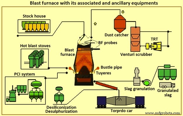
図1高炉とそれに関連する補助装置
BF製鉄は、調和して機能するいくつかのコンポーネントで構成されるシステムで構成されています。製鉄プロセスをサポートするには、これらのコンポーネントの適切な適用と操作が必要です。特定のコンポーネントの選択は、既存の条件、物理的な制約、生産要件、コスト、スケジュール、信頼性、保守性などの要因に依存します。コンポーネントの相互依存性は、個々の機能と同様に、システムの正常な動作にとって重要です。各領域またはコンポーネントには、主要な要件と「通常の」慣行があります。固有の長所と短所を持つ市販の代替技術もいくつかあります。
BFは鉄含有鉱石負荷を溶鉄(溶銑)に変換します。 BFに関連するのは、石炭をコークスに変換するコークス炉バッテリーと、BF用の鉄鉱石を準備する焼結およびペレットプラントです。 BFはこれらの準備された原材料をより価値の高い製品に変換します。一部のBF事業からの溶銑は、鋳鉄の製造のために鋳造所で使用されています。他の操作では、より低いシリコンの溶銑が製造され、これが製鋼工場で鋼に変換されます。溶銑の一部は、豚鋳造機で銑鉄に変換されます。 BFの副産物は、スラグ、BFトップガス、煙道ガス、フィルターケーキです。これらの副産物は、地域での利用の可能性に応じて、プラスまたはマイナスの経済的影響を与える可能性があります。
BFの設計または再設計のすべての考慮事項に影響を与えるいくつかの側面のいくつかは、(i)利益、(ii)従業員の健康と安全、(iii)環境保護、(iv)法定規制、(v)市場および下流の処理、(vi)利用可能な人的、建設、および保守のリソース、(vii)技術および機器の陳腐化の変化、(viii)利用可能な原材料、ユーティリティ、およびその他の材料、および(ix)など。これらの側面のいずれかに深刻な制約があると、BFユニット(または鉄鋼プラント)の実行可能性が危険にさらされたり、新しいBFの建設が妨げられたり必要になったりする可能性があります。
BFは通常、サイズごとにグループ化されます。ミニBFは1日あたり1,500トン未満の溶銑(tHM /日)を生成し、小型BFは約2,500tHM/日から5,000tHM/日の範囲で生成し、中型BFは約6,000tHM/日から8,000の範囲で生成します。 tHM /日、および大規模なBFは、約9,000tHM/日から12,000tHM/日を生成します。統合された鉄鋼プラントでは、鉄鋼の生産に必要な溶銑を提供するために、BFの数とサイズが必要です。 BFの数が多い統合製鉄所は、BFのリライニング修理が行われた場合、または炉の制御に問題がある場合の影響が少なくなります。小さいBFは、大きいBFよりもリライニングの修理が短く、操作が簡単であると考えられています。ただし、小さなBFからの溶銑のコストは高くなります。統合された鉄鋼プラントは、最小数の費用効果の高い炉を運転する必要があります。場合によっては、稼働中の炉の数を減らすためにアップグレードが行われます。
BFは、キャンペーンの終了後(リライニング修理間の時間)に定期的にリライニングされます。過去には、これには主炉の内部レンガライニングの交換が含まれていました。最近では、大規模なコンポーネントの再構築、交換、および予防保守が同時に実行されています。この方法では、大きなBFが少ないより効率的な鉄鋼プラントは、小さな炉の数が多いプラントよりも、BFリライニング修理中に生産量の高い割合を失います。 BFリライニング中の運用コストを低く抑え、干渉を最小限に抑えるために、業界はBFのキャンペーンを最大化し、リライニング修理の期間を短縮するように取り組んできました。統合製鉄所の現在の明確な傾向は、稼働する大型炉の数を減らし、BFキャンペーンを無期限に延長する技術と設計を利用することです。
同時に、製品のばらつきを減らすことがより重要になっているため、プロセスの監視と制御を改善する自動化への投資が行われています。 BFオペレーター、保守担当者、設計者、および研究担当者は、プロセスをより適切に監視および制御するために、最新のテクノロジーと分析手法をBFプロセスに適用しています。その結果、溶銑品質の標準偏差が減少しました。改善されたデータ収集システムはまた、サプライヤーとメーカーに増加した情報を提供します。これにより、材料の選択とBFおよび関連機器の設計が改善されました。キャンペーン期間は、以前は5年から10年に約20年に延長されました。
BF製鉄は430年以上前の技術です。それでも、BF溶銑の使用は、鉄鋼生産のための統合製鉄所で使用される最も一般的な方法です。現在の統合された鉄鋼プラントプロセスは、BFに依存して、一貫した品質の予測可能な量の溶銑をスケジュールどおりに提供しています。溶銑の供給のいずれかの側面の変動は、残りの鉄鋼生産プロセスに深刻な影響を及ぼします。したがって、BFは、現代の統合製鉄所の重要なプロセスであり続けています。
BFプロセス技術はその耐用年数の終わりにあると言われることがあります。これはそうではありません。中型BFの典型的なペアからの23年間(1970年から1993年)の運用データの研究は、年間3%の生産性の平均増加があることを示しました(図2a)。同時に、燃料率の平均低下は年間1%でした(図2b)。また、BFリライニング(キャンペーン)までの生産時間は、設備、材料、デザインの改善により延長されました。その結果、インフレを補正した溶銑製造の全体的なコストは、運転データが示すよりもさらに改善されました。したがって、BFプロセス技術は430年以上前の技術ですが、死んではいません。それはまだかなりの速度ですべての分野で進んでいます。 BFは今日でも、絶えず改善されているテクノロジーに支えられたダイナミックな科学です。
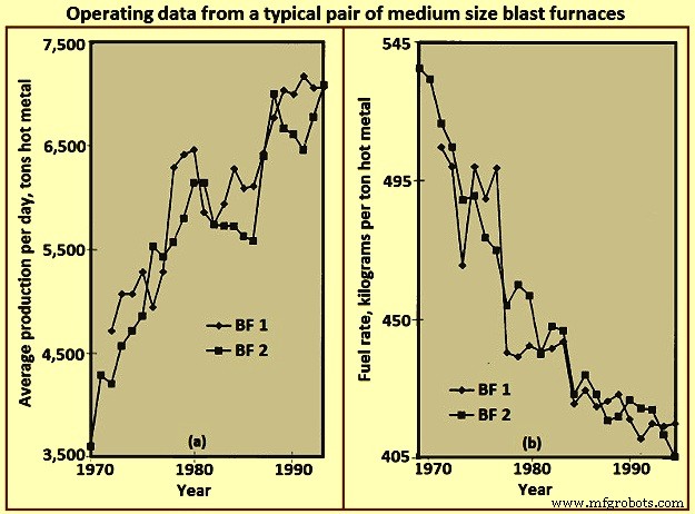
図2中型高炉の典型的なペアからの運転データ
BFのレイアウト
BFのレイアウトは、基本的に、溶銑とその結果生じる製品および副産物を製造するために必要なさまざまな材料を処理するために必要な機器を統合するための演習です。最も効率的な設計はプロセス全体に適切に対応し、その有効性は初期設備投資と継続的な運用コストの両方の観点から判断されます。 BFショップのレイアウトは、(i)敷地の地形、(ii)気候条件、(iii)原材料の配送方法、(iv)工場内の原材料の処理システムと場所、(v)下流の処理システム、場所、(vi)溶銑の量/流量要件、(vii)溶銑配送船団のタイプとサイズ、および(viii)など。図3は、BFプラントの簡略化されたレイアウトを示しています。
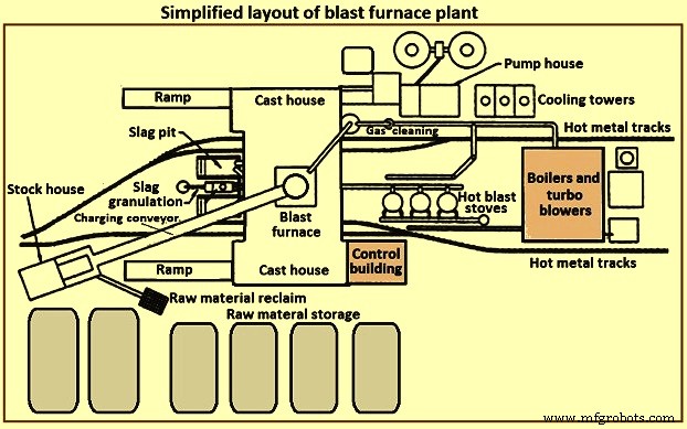
図3高炉プラントの簡略化されたレイアウト
BFプラントは通常、いくつかのセクションで構成されます。これらのセクションは、(i)原材料の保管、取り扱い、および再生利用、(ii)ストックハウス、(iii)チャージングシステム、(iv)炉本体、(v)キャストハウス、(vi)スラグの処理および取り扱い、(vii)です。溶銑の取り扱い、(viii)熱風ストーブと熱風システム、(ix)ガス洗浄プラント、(x)ユーティリティ、(xi)自動化および制御システム、(xii)保守施設、および(xiii)人員支援施設。
原材料の保管と取り扱い
鉄鉱石、石灰華、ペレット、フラックス、石炭、コークスなどの原材料は、外部ソースから受け取るか、統合された鉄鋼プラント内で生産されます。これらの原材料は、BF操作をサポートするために十分に管理された保管が必要です。予測可能な配信の中断または予測できない中断が発生した場合に備えて、ストレージ容量が必要です。特定の原材料の供給元が変更される可能性がある場合は、追加の保管容量が必要になることがあります。同様の材料では物理的または化学的特性が異なるため、別々の保管場所が必要です。同様の材料を混合すると、プロセス制御/冶金学的問題が発生する可能性があります。異なる材料の混合を防ぐために、保管パイルを分離する必要があります。原料再生装置のオペレーターがプライム材とトランプ材を区別できるように、杭は準備されたベッドに配置されます。材料の劣化を最小限に抑え、微粉の風による拾い上げを防ぐために、杭が配置されています。水噴霧と繭剤を使用して、風によるほこりの拾い上げ/持ち去りを最小限に抑えることができます。
原材料の敷設と回収には、いくつかの異なる手法が利用できます。レイダウン技術には、ワゴン転倒、鉱石橋、スタッキングコンベヤー、スクレーパーなどが含まれます。回収技術には、バケットホイールリクレーマ、ベンダーリクレーマ、フロントエンドローダー、スクレーパー、ビンまたはパイルの底から直接などが含まれます。システムは、BFプラントに必要なスループットを確保するようにサイズ設定する必要があります。
ストックハウス
ストックハウスは、炉に荷物を直接供給するためのBFオペレーターの保管ユニットです。 BFの負担材ごとに収納棚が用意されています。個々のビンは、異なる冶金学的特性を持つ同様の材料(つまり、焼結物、ペレット)用に提供されます。ストックハウスは、原材料保管エリアからの供給が短期的に中断した場合に備えて、さまざまな負担材料に十分な容量を提供します。原材料供給が失われた場合の一般的なストックハウスの処理能力は、(i)コークス– 2時間から8時間、(ii)鉄含有材料(鉱石、焼結体、ペレット)– 4時間から16時間、およびフラックスおよびその他のその他の材料–8時間から24時間。これらの容量は定格炉生産に基づいており、在庫またはサプライヤーからの交換の信頼性とアクセス時間によって異なります。
負担のある材料は、気候条件や繰り返しの取り扱いにより劣化する傾向があります。材料の処理回数(備蓄、再生、投棄、コンベヤーシュート、鉱石橋バケツなど)が高いほど、負担の罰金の割合が高くなります。 BFプロセスには、制御された透過性、したがって制御された負担が必要です。過剰な微粉の充填は、通常は充填全体を通して、または特定の短い充填期間に集中して、BFプロセスを混乱させ、炉設備に損傷を与える可能性があります。ストックハウスは、炉に投入する前に罰金を取り除くための最後の合理的な機会を提供します。可能な限り、コークス、鉱石、焼結鉱、ペレットの貯蔵ビンの後に振動スクリーンを設置して、微粉の大部分を排除します。除去された罰金はリサイクルのために回収されます。一部のBFオペレーターは、炉内の特定の領域に罰金を課して、局所的な炉の透過性を調整し、炉壁の熱負荷を制御します。
炉に充填された実際の水量を監視するために、ストックハウスには水分計が頻繁に設置されています。この情報により、充電量を調整して、さまざまな周囲条件(つまり、雨の期間中のより高いコークス水分)を補正することができます。
BFの連続運転をサポートするには、さまざまなタイプとさまざまな量の装入物が必要であるため、装入物は特定の順序で提供する必要があります(さまざまな炉の運転パラメータをサポートするために、それ自体を頻繁に変更できます)。したがって、ストックハウスには、特定のスケジュールを満たすために、正確な量の特定の負担材料を抽出して供給するための信頼性の高い機器が提供されます。図4は、ストックハウス内の簡略化された機器の配置を示しています。
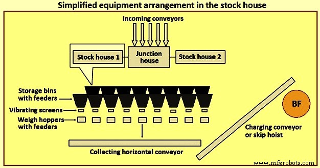
図4ストックハウス内の簡略化された機器の配置
以前、最も一般的なタイプのストックハウスはハイラインタイプでした。このタイプのストックハウスは、炉のすぐ隣にあります。鉄道車両またはブリッジクレーンは収納ビンに供給し、収納ビンは走行スケールカーに直接供給します。スケールカーのオペレーターは、ビン排出ゲートを手動で制御して、スケールカーにあるスケールを備えたホッパーに特定の量の材料を供給します。適切な種類と量の材料を収集した後、オペレーターはスケールカーを「スキップピット」の上の位置に移動し、シュートを介して待機中のスキップカーに荷物を降ろします。その後、スキップカーは炉の上部に持ち上げられます。
ハイラインタイプのストックハウスは、スケールカーと組み合わせて、鉄鉱石(鉱石、焼結鉱、ペレット)のスクリーニングを提供するためのいくつかのオプションを提示しました。 BFプロセスの知識が増えるにつれ、負担に対するより厳しい要件が生まれました。 「工学的負担」の概念は、今日、業界でよく認識されています。この要件をサポートするためのハイラインストックハウスの柔軟性と適応性には限界があると通常は認められています。そのため、ハイラインタイプのストックヤードは、BFにチャージ材料を供給するための自動コンベヤーストックハウスに置き換えられました。
自動ストックハウスは通常、2つの異なるタイプです。最初のタイプは、原材料ビンの下のスケールカーをフィーダーとコンベヤーベルトシステムに置き換えることです。貯蔵ビンの列が取り付けられている原材料(コークス、鉄含有材料、フラックス材料および添加剤など)ごとに個別のコンベヤーが用意されており、振動フィーダーが貯蔵ビンからコンベヤーに負担物を排出します。コークスと鉄を含む材料の場合、振動スクリーンが各コンベヤーの排出口に配置され、材料をふるいにかけ、ふるいにかけられた材料を計量ホッパーに供給します。このタイプのシステムは、スキップカーの前に計量ホッパーに供給し続けます。
自動ストックハウスの2番目のタイプは、完全に地上に建てられ、BFからかなり離れた場所に建てられた大きな構造の貯蔵庫です。これは通常、スキップカーの代わりにベルトコンベヤーを使用して装入物を炉の上部に運ぶBFに対して行われます。貯蔵ビンを充填する方法は、通常、コンベヤーベルトシステムによるものです。原材料は、振動フィーダーとベルトコンベヤーによって貯蔵ビンから計量ホッパーに引き込まれます。次に、計量ホッパーは、収集コンベヤーを使用して材料をメインコンベヤーに排出します。計量ホッパーは、炉の上部にあるメインコンベヤーベルトに正しい順序で原材料を計量するようにプログラムされています。
自動化されたストックハウスを提供することで、ストックハウスへの原材料のより効率的な供給と、炉への負担のより効率的な選択、スクリーニング、計量、および配送を提供できます。自動スタックハウスは、炉の供給スキップカーに直接隣接して配置することも、コンベヤーベルトを介して充填するために炉から離れた場所に配置することもできます。
ストックハウスの自動化により、生産能力が大幅に向上し、運用効率が向上し、オペレーターや機器に起因する運用上の差異がなくなりました。ただし、実際には、最新の自動化されたストックハウスは非常に複雑になる可能性があります。ストックハウス自体はコンベヤーによって供給され、コンベヤーはトリッピングコンベヤーに排出されて材料をさまざまなビンに分配します。ストックハウス内のコンベヤーと機器のレイアウトは、さまざまな方法で配置できます。炉に隣接してストックハウスを配置すると、レイアウトが混雑し、将来の変更に対する柔軟性が制限されることがよくあります。
吊り上げシステム
積載物は通常、スキップカーまたはコンベヤーベルトを使用してBFトップに吊り上げられます。
車の巻き上げをスキップ – BFでのスキップカーの使用は、鉱業から発展しました。 BFスキップカーは、炉のスループットに合わせたサイズになっています。明らかに、ホイスト容量、スキップブリッジの設計などのいくつかの要因は、スキップサイズに独自の影響または制約を持っています。
通常、2つのスキップは、共通のホイストで(必要な巻き上げ力を減らすために)反対の方法で動作します。スキップは、通常、水平から60度から80度の傾斜で設置される、スキップブリッジのレール上を移動します。フルスキップは、スキップピットを離れるときにゆっくりと加速し、リフトの大部分で最大速度に到達して移動するときにできるだけ速く加速します。ホイストは、スキップブリッジの上部に近づくにつれて、スキップダウンを遅くします。スキップがファーネストップチャージング装置に転倒すると、スキップのホイールはダンピングレールとホーンレールによってガイドされます。巻き上げスキップが最後のダンプ位置に到達して停止すると、空のスキップ(同じ速度で下降)がスキップピットへの移動の最下部に到達し、充填を待機します。スキップチャージングシステムは、炉の上部に負担をかけるための信頼性が高く効果的な技術です。ただし、スキップは特定の量の材料しか保持できない(過負荷は過充填または過剰なホイスト負荷をもたらす)、または少量の特定の負荷が必要な場合は非効率になるという点で、オペレーターにとって柔軟性に欠けます。図5は、スキップカーの巻き上げの概略図を示しています。
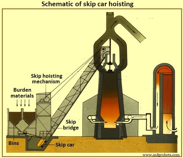
図5スキップカーの巻き上げの概略図
炉装入コンベヤー –ストックハウスのコンベヤー化に伴い、巻き上げシステムのコンベヤー化が行われました。現在、ストックハウスは炉から離れた場所に配置されるのが一般的であり、1つの大きなコンベヤーベルトが炉の上部に負担をかけます。炉の上部が約60メートルの高さで、水平位置に対して8度の傾斜でコンベヤーベルトが設置されている場合、ストックハウスは炉から少なくとも427メートルの位置に配置する必要があります。材料のロールバックを最小限に抑えるために、通常、ベルトの傾斜が急になることは避けられます。炉の上部に到達するまで鉄系材料を所定の位置に保持するために、コンベヤーベルトでの鉄系装入の終了直後に、その他の材料を直接装入するのが通常です。
炉上部の充電システム
炉自体は正の高い上部圧力で操作されます。一酸化炭素、二酸化炭素、窒素で部分的に構成される高炉ガスは、大量の同伴ダストとともに高炉ガスプロセスによって生成されます。 BFオペレーターは、プロセスの利点のために最高圧力を維持し、ガスとほこりを封じ込める必要があります(燃料価値と環境制御の両方の目的で)。ただし、オペレーターは、炉の上部圧力を失うことなく、内部プロセスを補充するために、炉の上部に定期的に装入物を配置する必要があります。
ベルタイプトップ –数年の間、最も一般的なタイプのファーネストップは2ベルトップでした(図6)。負荷が(スキップまたはコンベヤーによって)炉の上部に到達すると、それは受け入れホッパーと小さなベルホッパーに落下します。小さなベル(直径約2.6メートル、高さ1.4メートル、1日あたり5,000 tHM BFの円錐形の鋳鋼)が下がり、大きなベルホッパーに負担がかかるようになります。小さなベルが持ち上げられ、小さなベルホッパーの固定シートに対してシールされます。大きなベルホッパーの容量に応じて、小さなベルによって大きなベルホッパーに追加の負荷が順番に割り当てられます。このプロセスの間、大きなベルは閉じたままで、炉を密閉します。負荷の正しい数の負荷が収集されると、大きなベル(直径約5.5メートル、高さ約3.5メートル、1日あたり5,000 tHM BFの円錐形の鋳鋼)が下がり、負荷をベルに滑り込ませます。適切な炉の上部。荷物が排出された後、大きなベルが持ち上げられ、大きなベルホッパーの下側を密閉します。図6にベルタイプのBFトップチャージングシステムを示します。
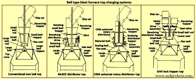
図6ベル型高炉トップチャージングシステム
明らかに、このタイプのトップの炉による負荷分散制御は、大きなベルにどれだけ均等に負荷がかかるか(スキップダンプにより、このタイプのトップに負荷が不均一に配置される)と、大きなベルから滑り落ちて落ちる特定の負担材料(つまり、コークスまたは鉄の負担)。さらに、2つのベルトップは、大小のベルのシーリング、および大ベルロッドと小ベルチューブの間のパッキンのシールが失われる可能性があります。ベルの漏れは、ベルのシール面上を滑る負担材による摩耗に起因します。ロッドパッキンの漏れは、炉内からの微粉による摩耗、または荷が受け入れホッパーにダンプされた後の大きなベルロッドへの収集による摩耗の結果です。
大きなベルシール面の摩耗を最小限に抑えるために、炉内から採取したBFガスをベルの間に導入して、スペースを均等にします(大きなベルシール面全体の圧力差を低減します)。このガスは、小さなベルを開く前に大気に放出され、より多くの負担をかけることができます。 2ベルタイプのトップシステムの制限を改善するために利用できるオプションのいくつかを以下に示します。
McKEEディストリビューター – McKEEディストリビューター(図6)は、2ベルタイプのトップで利用可能な主な負担分散の改善でした。しかし、それはすぐに他の技術に取って代わられています。その設計には、スキップカーの排出中にスモールベルとスモールベルホッパーを一緒に回転させる機能が組み込まれています。負担は小さなベルホッパーに均等に分散されるため、大きなベルへの負担の均等な配置が改善されます。このタイプのトップは、ベルが小さくて大きく摩耗し、その後シール効果が失われる傾向があります。
CRMユニバーサルロータリーディストリビュータートップ – CRM(Centre Recherches Metallurgiques –ベルギー)ユニバーサルロータリーディストリビューター(図6)は、小さなベルシーリング効果の損失を排除するために開発されました。通常の小さなベルの代わりに、2つのベル(シーリングベルとマテリアルベル)が取り付けられています。素材ベルには回転式負担ホッパーが取り付けられています。シーリングベルは素材ベルの下にあり、固定シートに対してシールします。スキップ排出中は、負担ホッパーとクローズマテリアルベルを回転させてホッパーを均等に満たします。充填が完了すると、ホッパーの回転が停止します。大きなベルにダンプするときは、回転ホッパー、材料ベル、シーリングベルを下げます。シーリングベルは固定シートの下に下がります。下降プロセスの途中で、ホッパーの下降が停止し、材料ベルとシーリングベルが停止位置に到達するまで下降を続けます。材料ベルとホッパーの間に隙間が開くと、大きなベルホッパーに負荷が均等に排出されます。負荷が隙間を離れるので、シールバルブの着座面に接触せず、トップシール能力を維持します。このスタイルのトップは、0.2MPaの内圧を維持できます。
CRMトップは、2つのベルトップのシーリング機能と寿命を向上させます。ただし、McKEEディストリビューターに比べて炉の負荷分散が劇的に改善されるわけではなく、大きなベルシール面の脆弱性を排除するものでもありません。
GHHロックホッパートップ – GHHロックホッパートップ(図6)は、2ベルトップを変更したものです。ガスシールを維持するために大きなベルへの依存を減らします。スキップダンプの場所ごとに個別のシールバルブを備えたロックホッパーを追加すると、上部をシールするための追加の容量が提供されます。大きなベルは、そのシール面全体に差圧なしで操作できます(つまり、炉の上部圧力は大きなベルホッパー圧力に等しくなります)。操作は以下のとおりです。
スキップは、受けホッパーと開いたシールバルブを介してロックホッパーに負荷の負荷をダンプします。負担は回転する小さなベルにかかり、小さなベルの上にある回転するディストリビューターホッパーを均一に満たします。回転中は、ロックホッパーと回転するスモールベルホッパーの間のシールが開いています。スキップからの負荷排出が終了すると、シールバルブとロックホッパーとスモールベルホッパーの間のシールが閉じられます。イコライジングガスが導入され、ロックホッパーが炉の最高圧力まで加圧されます。次に、小さなベルを下げて、大きなベルホッパーに負担をかけます。小さなベルが閉じ、ロックホッパーからの圧力が大気に解放されます。反対側(つまり、もう一方のスキップダンプ位置)のシールバルブが開きます。ロックホッパーとスモールベルホッパーの間のシールが開きます。小さなベルとホッパーの回転が始まります。トップは、他のスキップからの負担を受け入れることができるようになりました。
このタイプのトップは、2つのベルトップのシーリング能力と寿命を向上させます。ただし、ロックホッパートップは、McKEEまたはCRMトップよりも劇的な炉負荷分散の改善を提供しません。シーリング機能を実行するために大きなベルは不要になりましたが、小さなベルのシーリング効果の寿命は依然として重要です。
可動装甲 –ベルタイプのトップの負担分散を改善するために取られた主要なステップは、可動装甲の開発でした(図7)。調整可能なデフレクターが炉のスロート領域に取り付けられており、大きなベルから滑り落ちた後の負荷をそらすことができます。可動装甲は、排出される特定の装甲材料と、オペレーターが炉内のどこに装甲を配置したいかに応じて調整されます。
いくつかのメーカーは、さまざまな種類の可動装甲を提供しています。個々の装甲セグメントは、炉内で均一に(同時にそして等しく)移動して、負荷を環状パターンに配置することができます。非円形の分布パターンを実現するために、装甲板を個別に制御するために、他のタイプの可動装甲が利用可能です。
可動装甲に関連するいくつかの欠点は、(i)機械部品と摩耗部品の大部分が炉の上部コーンの過酷な環境にあること、(ii)可動装甲と設計ストックラインの間にクリアランスを提供するために内部作業量の損失が必要であることです。レベル(ただし、炉のこの領域は、炉の作業量を考慮するための大まかな生産性ゾーンとして分類することはできませんが、(iii)特にストックラインレベルがすでに高い場合は、負荷を炉の中心にそらす能力が制限されます。ペレットの特性は、可動装甲の限られた変位をしばしば打ち消します。
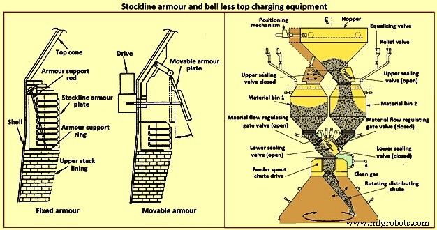
図7ストックラインアーマーとベルレストップチャージング機器
ベルレストップ充電システム – 1970年代初頭、ルクセンブルクのPaul Wurth S.A.は、ベルレストップ(BLT)充電システムを開発しました(図7)。このタイプのファーネストップは、ベルタイプのトップとは一線を画しています。負荷は、炉のオペレーターが必要とする任意のパターンで炉内に配置できます。環状リング、スパイラル、セグメント、およびポイントの配置は、炉の上部コーンに配置された負荷分散シュートの同期または独立した傾斜と回転によって達成可能な一般的なパターンです。
炉の上部シーリングは、炉のキャンペーン全体を通して維持されます。メンテナンス作業は簡単で短時間です。通常、BLTは、受け取りシュートまたはホッパー(スキップまたはコンベヤーベルトからの負荷を受け取る)、上下のシールバルブを備えたロックホッパー、マテリアルフロー制御ゲート、メインシュートドライブギアボックス(水またはガス)で構成されます。 -シュートの回転と傾斜に使用される冷却ユニット)、および負荷分散シュート。 BLTには、主に(i)パラレルホッパー、(ii)セントラルフィード、(iii)コンパクトタイプの3つのタイプがあります。
通常、パラレルタイプには2つのロックホッパーが組み込まれています(ホッパーはスループットとバックアップの目的で一部の炉に取り付けられています。1つの「エキセントリック」ホッパータイプは、クリアランスが制限されているアプリケーション用に取り付けられています)。 1980年代初頭以来、いくつかのBFは、負荷の分離と負荷の分散制御を改善し、炉の操作を改善するために、「中央供給」シングルロックホッパータイプを選択しました。
「コンパクト」タイプのBLTトップは、中小規模の炉用に開発されており、コストや物理的制約のために他の大型タイプのBLTを使用できない炉にBLT(およびその利点)を導入できます。セントラルフィードタイプのBLT操作の手順は、(i)負荷がスキップまたはコンベヤーベルトから受け取りシュートまたはホッパーを介して開いたシールバルブを通過してロックホッパーに排出される、(ii)負荷がロックで受け取られた後です。ホッパーでは、上部シールバルブが閉じられ、均等化ガスが導入されてロックホッパーが炉圧に加圧されます。(iii)下部シールバルブが開きます。(iv)材料ゲートが排出される特定の負荷材料に合わせて事前に選択された開口部、(v)フィーダーがメイントランスミッションギアボックスを備えた噴出口から垂直に落下し、負荷分散シュートに落下する、(vi)負荷分散シュートが負荷を必要なものに向けるpoint(s) within the furnace, (vii) when the lock hopper is fully discharged (monitored by load cells and / or acoustic monitoring), the lower seal valve is closed, (viii) a relief valve is opened to exhaust the lock hopper to atmosphe re (or through an energy recovery unit), and (ix) the upper seal valve opens and the sequence is repeated.
The advantages of BLT over other top charging systems include higher top pressure capability (i.e. 0.25 MPa), fuel savings, increased production, more stable operation, reduced maintenance in terms of cost and time, increased furnace campaign life, and improved furnace operational control when employing high coal injection rates at the tuyeres.
Gimbal system of charging – The purpose of the Gimbal system of charging is to facilitate controlled distribution of charge material into the BF via a Gimbal type oscillating chute through a holding hopper and variable material gate opening such that the pressurized charging system above can operate independently of the distribution system. It utilizes a conical distribution chute, supported by rings in a Gimbal arrangement, producing independent and combined tilting of the chute axis. The Gimbal distributor, as part of the overall BF top charging system, offers a fully integrated charging solution, generating considerable improvement in BF operation and maintenance cost. The Gimbal system utilizes a conical distribution chute, supported by rings in a Gimbal arrangement, producing independent, and combined tilting of the chute axis.
The Gimbal top incorporates a full complimentary range of furnace top distribution equipment including distribution rockers, upper seal valves, hoppers, lower seal valves, material flow gates and goggle valve assemblies, all discharging through hydraulically driven distribution chutes. The tilting chute is driven by two hydraulic cylinders, mounted 90 degree apart. This type of suspension and drive arrangement results not in a rotation of the tilting chute, but in a circular path by superposition of both tilting motions. Independent or combined operation of the cylinders allows the chute axis to be directed to any angle, or even along any path. Motion is supplied by two hydraulic cylinders, each operating through a shaft, connecting rod, and universal joint in order to drive the Gimbal rings. Through the movement of the hydraulic cylinders, the distribution chute allows precise material distribution with potential for an infinite number of charging patterns at varying speeds. These include ring, spiral, centre, spot, segment or sector charging, providing complete control of material charging into the furnace.
The whole distributor assembly is enclosed in a gas tight housing, which is mounted directly onto the top flange of the BF top cone. The housing contains a fixed inlet chute and a tilting distribution chute supported by rings in a Gimbal arrangement allowing independent and combined tilting of the chute axis. The assembly is made from a combination of stainless and carbon steel material with the fixed inlet chute and tilting chute body lined with ceramic material to give superior wear protection. A closed-circuit water cooling system supplies cooling water through the main shafts, Gimbal bearings, and universal joint bearings in order to cool the moving elements of the Gimbal distribution system.
The key features of the Gimbal design are (i) simple, rugged design, using levers driven by the hydraulic cylinders, (ii) drive cylinders are mounted outside pressure envelope, hence not subject to hot and dusty service conditions, (iii) Gimbal ring arrangement gives simple tilting motion in two planes, which when superimposed gives 360 degrees distribution, and (iv) wear on the tilting chute is equalized around its circumference giving a long extended operational life.
The BF Gimbal top is an automated, computer-controlled pressurized charging system designed to (i) receive charges of ore, coke, and miscellaneous materials in the holding hopper, independently of the distribution system below, (ii) release those discharges, as needed, to a dynamic distribution chute located below the holding hopper, and (iii) distribute material in prescribed patterns to the furnace stock-line in accordance with a predetermined charging matrix. Control of the Gimbal distribution chute is fully integrated into the overall furnace charging software. The system provides a high level of accuracy and control for the Gimbal movements and hence the positioning of the distribution chute. Gimbal material distributor is shown in Fig 8.
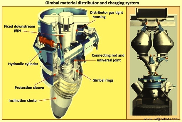
Fig 8 Gimbal material distributor and charging system
Furnace proper
The furnace proper is the main reactor vessel of the BF ironmaking process. Its internal lines are designed to support the internal process. Its external lines are designed to provide the necessary systems to contain, maintain, monitor, support, and adjust the internal process.
The BF process is a counter flow process. The process comprises of (i) burden at ambient conditions is placed in the furnace top onto the column of burden within the furnace, (ii) as the burden descends with the burden column, it is heated, chemically modified, and finally melted, (iii) further chemical modifications occur with the molten material, (iv) the molten products are extracted near the bottom, (v) melting of the burden material and extraction result in the descent of the burden column and the need for replenishment of the burden at the top, (vi) hot blast air is introduced through tuyeres near the bottom, (vii) BF gases are generated in front of the tuyeres and ascend through the burden and chemically modify the descending burden as well as themselves get chemically modified and cooled, (viii) BF gas (and dust) is extracted near the top of the furnace, and (ix) heat is extracted from the vessel in all directions (primarily through the lining cooling system) and along with the BF gas, liquid iron and liquid slag. Fig 9 shows cross section and types of BF.
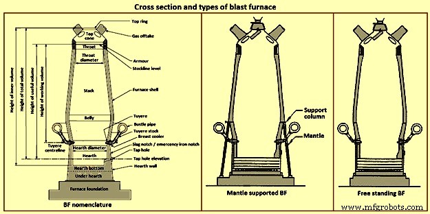
Fig 9 Cross section and types of blast furnace
Furnace type – Furnaces are constructed to be mantle supported or free standing. Mantle supported BFs characteristically have a ring girder (mantle) located at the bottom of the lower stack of the furnace. The mantle is supported in turn by columns which are on the main furnace foundation. The hearth, tuyere breast, and bosh are also supported by the foundation. Furnaces with mantle support column tend to have restricted access and reduced flexibility for improvements in the mantle, bosh, and tuyere breast areas.
Since thermal expansion is a major consideration in furnace shell design, the mantle style of furnace provides an interesting design consideration. The mantle support columns are relatively cool. The mantle tends to maintain a constant height, throughout the furnace campaign with respect to the furnace foundation. Thermal expansion of the stack due to process heat is considered to be based at the ‘fixed’ mantle (i.e. the top of the furnace raises with respect to the mantle). The effective height of the bosh, tuyere breast, and hearth wall shells (supported on the furnace foundation) increases due to the thermal expansion of the shell caused by the process heat. The lower portion of the furnace lifts upwards towards the fixed mantle. Hence, the provision of an expansion joint of some type is needed at the bosh / mantle connection or somewhere appropriately located in the lower portion of the furnace.
Free standing furnaces have been developed to eliminate the column and permit the installation of major equipment and furnace cooling improvements. This furnace type has a thicker shell for structural support. Installation and maintenance of a reliable cooling and lining system is necessary in order to sustain the structural longevity of the shell.
Two variations of the free standing furnace have been used. One type provides for a separate structural support tower to carry the furnace off-gas system and charging / hoisting system load. The other type (while it does employ a separate support tower for shell replacement purposes during relines) uses the furnace proper to support the off-gas system and charging / hoisting system loads. Special consideration to the furnace shell design is to be made regardless of the furnace type. The furnace vessel is subjected to internal pressures from the blast and gas, burden, liquid iron and slag. Dead and live load during all operating, maintenance, and reline stages are to be considered as well.
Furnace zones – The major zones of the furnace proper are (i) top cone, (ii) throat, (iii) stack, (iv) mantle / belly, (v) bosh, (vi) tuyere breast, (vii) hearth walls, (viii) hearth bottom, (ix) foundation.
Top cone – The top cone or dome is the uppermost part of the furnace proper. It supports the furnace top charging equipment, and the BF top gas collection system. Stock rods (stockline recorders or gauges) are normally placed here to monitor the upper level of the burden in the furnace. These devices are the units which provide the permissive or indication signals to charge the next scheduled burden input to the furnace. Typically, they are weights lowered by special winches, or microwave units. Some furnaces incorporate radio-active isotope emitters and detectors mounted in the furnace throat to monitor the burden level. Infrared camera can be installed in the top cone to monitor the BF top gas temperature distribution as it escapes the furnace burden stockline.
The top cone is the coolest zone of the furnace proper but can be exposed to extremely high temperatures if burden ‘slips’ (rapid, uncontrolled burden descent after a period of unusual lack of descent). The newly charged burden falls through this zone and the BF top gas is carried away from this section.
Throat – Steel wear plates or armour are installed in this zone. Here, abrasion of the furnace lining from the charged burden is the prime cause of deterioration. Furnace operators work to maintain the upper level of the burden (the stockline) in this region. Movable armour can be installed in this area in order to deflect the burden falling from a large bell. With the installation of the BLT, wear of the stockline area can be greatly reduced. Some BF users select to eliminate the armour plates and use an abrasion resistant refractory lining instead.
Stack – The stack (sometimes called shaft or the ‘in-wall’) is the zone between the mantle or belly on a free standing furnace and the stockline area. Smooth, uniform lines (the process ‘working surface’) of the stack are essential for uniform and predictable burden descent, BF gas ascent, and stable process control throughout the furnace campaign. Process considerations dictate a larger diameter at the base of the stack than at the top. Typical stack angles are in the range of around 85 degrees from the horizontal.
Mantle / belly – The mantle or belly area provides the transition between the expanded stack and bosh sections. Maintenance of the effectiveness of the cooling / lining system is particularly important for the mantle type furnace in order to protect the mantle structure. Thermal protection is important for the free standing furnace type as well. However, the free standing design is less complicated and more accessible in this area.
Bosh – The bosh area lies between the tuyere breast and the mantle / belly of the furnace. The bosh diameter increases from bottom to top. The inclination of the bosh permits the efficient ascent of the process gases and has been found to be necessary in order to provide the needed zone service life (the process gases are extremely hot and internal chemical attack conditions are severe). Typical bosh angles are in the range of around 80 degrees from the horizontal. Boshes are of two basic types, namely (i) banded and (ii) sealed. They can be cooled by different techniques.
Banded boshes are found in older mantle supported furnaces (they cannot be applied to free standing furnaces). A number of steel bands are placed in incrementally increasing diameters (smallest at the bottom of the bosh and largest at the top) and are tied together with connecting strips. Gap between the bands permits the introduction of copper cooling plates. Ceramic brick lining is to be used as air infiltration results in oxidation of carbon based linings. Gas leakage through the banded bosh can be high. This type is not suitable for BFs with high blast pressure / high top pressure. Banded boshes provide adequate flexibility to eliminate the requirement for a shell expansion joint in the lower portion of the furnace.
Sealed boshes, using continuous steel shell plate instead of separate bands, are employed to permit the use of improved cooling / lining systems, higher furnace operating pressures, and the free standing furnace type. Sealed boshes retain valuable gases with the furnace, hence improving the metallurgical process. As well, the seal bosh, since it precludes air entry into the lining, supports the use of carbon based refractories.
Tuyere breast – Hot blast air is introduced to the furnace through tuyeres (water-cooled copper units) located within the tuyere breast. The number of tuyeres needed depends upon the size (production capacity) of the furnace. The tuyere breast diameter, tuyere spacing, and number of tuyeres are influenced by the expected raceway zone size in front of each tuyere.
Tuyere stocks (Fig 10) convey the hot blast air from the bustle pipe to the tuyeres. The tuyeres are supported by tuyere coolers (water-cooled copper units) which are in turn supported by steel tuyere cooler holders (either welded or bolted to the furnace shell). Special consideration are to be made in the tuyere breast shell and lining design in order to maintain effective sealing of the different components in order to prevent escape and loss of the furnace gases.
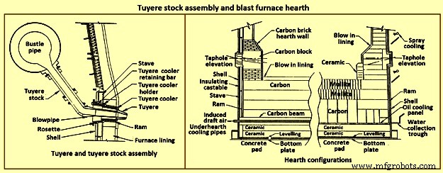
Fig 10 Tuyere stock assembly and blast furnace hearth
Hearth – The hearth (Fig 10) is the crucible of the furnace. Here, hot metal and liquid slag are collected and held until the furnace is tapped. The hearth wall is penetrated by tap holes (frequently called iron notches) for the removal of the collected hot metal and liquid slag. The number of tap holes is dependent upon the size of the furnace, hot metal, and liquid slag handling requirements, physical and capital constraints etc.
Several furnaces are equipped with a slag or cinder notch (normally one per furnace, although some furnaces can have two). The slag notch opening elevation is normally sufficiently higher than the iron notch elevation. In earlier days, when slag volumes were high, the slag was flushed from the slag notch periodically. This simplified the iron / slag separation process in the cast house. More commonly now, however, the slag notch is retained solely for initial furnace set-up procedures or for emergency use in case of iron notch or other furnace operating problems.
Hearth bottom – The hearth bottom supports the hearth walls and is flooded by the iron within the furnace. As the campaign progresses, the hearth bottom lining wears away to a fixed equilibrium point. The remaining refractory contains the process and with sufficient cooling or inherent insulation value protects the furnace pad and foundation.
Cooling system
The application of specific cooling techniques to individual furnace zones is dependent upon several factors such as campaign life expectancy, furnace operational philosophy, burden types, refractories, cost constraints, physical constraints, available cooling media, and preferences etc. Different cooling techniques can be provided for different zones to assist the lining to resist the specific zone deterioration factors. Normally, the provision of adequate cooling capacity is necessary in each of the applicable furnace zones if the lining system located there is to survive. Where the thermal, chemical, and to some extent the abrasive conditions of the process are extreme, sufficient cooling is to be provided to maintain the necessary uniform interior lines of the furnace and to protect the furnace shell.
Typically, the top cone and throat areas of the furnace are not cooled. The hearth bottom can be ‘actively’ cooled by under hearth cooling (air, water, or oil media) or ‘passively’ cooled by heat conduction though the hearth bottom lining to the hearth wall. The basic cooling options for the balance of the furnace are (i) no cooling (typically the upper portion of the stack is not cooled in several furnaces, (ii) shower or spray cooling, (iii) jacket or channel cooling, (iv) plate cooling, and (v) stave cooling.
Shower or spray cooling – Water is directed by sprays or by overflow troughs and descends in a film over the shell plate. Effective spray nozzle design, numbers and positioning are important for proper coverage and to minimize rebound. Proper deflector plate design is necessary to ensure efficient cooling water distribution and to minimize splashing. Shower cooling is frequently employed in the bosh and hearth wall areas. Spray cooling is normally applied for emergency or back-up cooling, primarily in the stack area. Exterior shell plate corrosion and organic fouling are common problems which can disrupt water flow or insulate the shell from the cooling effect of the surface applied cooling. Water treatment is an important consideration to retain effective cooling.
Jacket or channel cooling – Fabricated cooling chambers or indeed structural steel channels or angles are welded directly to the outside of the shell plate. Water flows at low velocity though the cooling elements in order to cool the shell and the lining. Jacket or channel cooling is frequently applied to the hearth walls, tuyere breast, and bosh areas. Scale build-up on the furnace shell and debris collection in the bottoms of the external cooling elements can compromise the cooling effectiveness. Hence periodic cleaning of the cooling elements is necessary.
The critical area of concern in the cooling schemes mentioned so far is the necessity for the shell plate to act as a cooling element. If extreme heat loads are acting upon the inside face of the shell, then there exist an extremely high thermal gradient across the shell. This effect results in high thermally induced shell stresses and eventual cracking. The cracks start from the inside of the furnace and propagate to the outside. The cracks remain invisible (other than a ‘hot spot’) until they fully penetrate the shell plate. Through cracking of the shell plate results in the leak of the BF gas, exposed shell carburization, and disruption of the cooling effect (particularly spray or shower cooling). Shell cracking into a sealed cooling jacket or channel is difficult to locate and can result in long furnace outage time for repair. Entry of water into the furnace (frequently when the furnace is off-line and internal furnace gas pressure cannot prevent entry of cooling water though shell cracks) can have detrimental effect upon the furnace lining. Water in the furnace can be potentially dangerous due to explosion risk (steam or hydrogen). Since shower and jacket cooling rely on the shell plate to conduct the process heat to the cooling media, the plate and stave cooling are configured to isolate the shell from process.
Plate and cigar cooling – Installation of cooling elements though the shell of the furnace (Fig 11) has been a major furnace design improvement resulting in effective cooling of the furnace lining and protection of the shell plate. Cooling is provided along the length of the cooling element penetration into the lining. The inserted elements provide positive mechanical support for the refractory lining. Typical cooling plate manufacture is cast high conductivity copper. Single or multiple passes of cooling water can be incorporated. Cooling boxes with larger vertical section have been produced from cast steel, iron, or copper.
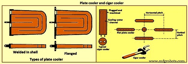
Fig 11 Plate cooler and cigar cooler
Cigar type (cylindrical) coolers (Fig 11) of steel and /or copper have also been successfully used. The philosophy of dense plate cooling (i.e. vertical pitch of 350 mm to 400 mm centre-to- centre, and horizontal pitch of 600 mm (centre-to-centre) has improved the cooling effect and increased lining life.
Copper cooling plates have traditionally been anchored in the shell plate with retainer bars or bolted connections to permit ready replacement if plate leakage occurs. More recently, plates have been designed with steel sections at the rear of the plate for welding directly to the steel shell. While sometimes taking longer to replace, this type provides a positive seal against BF gas leakage. Plate coolers are typically installed in areas above where the liquid iron collects in the furnace. Hence the mid-point of the tuyere breast, right up to the underside of the throat armour is the range of application.
Stave cooling – Cast iron cooling elements (Shannon plates or staves) have been used for several years in the bosh and hearth wall areas. These castings have cored cooling passages of large cross-section. While their service life have been not remarkable in the bosh, multiple campaigns have been normal for the hearth wall. These staves frequently suffered from low flow rates of marginal quality cooling water (scaling and debris deposition / build-up) and sometimes casting porosity. Water leaks into the hearth wall can be a considerable problem.
In the 1950s, the then USSR developed a new type of stave cooler (Fig 12) and ‘natural evaporative stave cooling’. For this design, castings were of gray cast iron containing steel pipes for water passes. The pipes were coated prior to casting to prevent carburization of the cooling pipe and metallurgical contact with the stave body material. The staves were installed in horizontal rows with the furnace and the cooling pipes projected through the shell. Vertical column of staves were formed by the inter-connection of the projecting pipes from one stave up to the corresponding stave in the next row. Staves can be applied to all the walls in the zones below the armour. Staves in the hearth wall and tuyere breast are supplied with smooth faces. Staves in the bosh, mantle / belly and stack normally have rib recesses for the installation of refractory.
Evolution of the stave cooler design has been dramatic. Staves in the higher heat load areas are now typically cast from ductile iron for improved thermal conductivity and crack resistance. While early stave design used castable refractory (installed after stave installation within the furnace), ribs now normally incorporate refractory bricks, either cast in place (with the stave body at the foundry) or slid and mortared in place prior to installation in the furnace. Fig 12 shows stave cooler and generations of stave development.
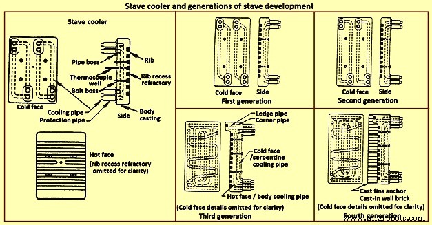
Fig 12 Stave cooler and generations of stave development
Staves are normally expected to retain a refractory lining in front for some time. After loss (expected) of the lining the staves are designed to resist the abrasive effects of descending burden and ascending dirty gas. As well, they are to absorb the expected process heat load and resist thermal load cycling and shock. Four generations of staves (Fig 12) are normally recognized in the industry.
First generation staves are no longer normally used. These staves have four cooling body circuits (with long radius bends which do not effectively cool the stave comers. These staves are made of gray iron castings with castable rib refractory. Second generation staves have four cooling body circuits with short radius bends for improved comer cooling. These staves are made of ductile iron castings with cast-in or glued-in rib bricks. Third generation staves have two-layer body cooling incorporating four or six cooling body circuits (stave hot face) and one or two serpentine cold face circuits (stave cold face) for additional or back-up cooling in the event of hot face circuit loss. These staves have additional edge cooling (top and bottom). The more frequent use of these staves is as cooled ledges to support a refractory lining. These staves have cast-in or mortared-in rib bricks. Fourth generation staves have two-layer cooling (similar to third generation). These staves have cooled ledges and cast-in wall brick lining eliminating the need for a manually placed interior brick lining.
Staves incorporating hot face ledges are more effective in retaining a brick lining than the smoother rib faced bricks. However, once the brick lining disappears, the ledges are very exposed within the furnace. The ledges disrupt burden descent and gas ascent. Exposed ledges tend to fail quickly. They are frequently serviced by cooling water separate from the main stave cooling circuit(s). In this way leaking ledge circuits can be more easily located or isolated. Some stave manufacturers are now providing separate ledge castings so that ledge cracking and loss does not damage the parent staves. As well, there is some present change in philosophy to abandon the application of ledges entirely.
Variations of the basic stave generation types are common. For example, staves of fourth generation type utilizing a refractory castable for the wall ling have been employed successfully. Alternatively, brick linings have been anchored to the stave bodies. Such approaches can be used to substitute for brick support ledges.
A ‘fifth’ generation of staves design has been the developed. It is the copper stave (Fig 13). The development of copper staves was carried out both in Japan and Germany for use in the region of bosh, belly, and lower stack to cope with high heat loads and large fluctuations of temperatures. While Japan has gone for cast copper staves, German copper staves are rolled copper plates having close outer tolerarnces and with drilling done for cooling passages. Drilled and plugged copper staves are typically designed for four water pipes in a straight line at the top and four water pipes in a stright line at the bottom. Materials for internal pipe coils include monel, copper, or steel. Unlike cast iron staves, copper staves are intended to be bonded to the cooling pipe.
The development of the cast-in copper stave has considered the following aspects. As per the first aspect, for the prevention of deformation, appropriate design of the stave length and bolt constrained points is important. The first aspect is that the use of the cast-in steel pipe copper stave with its own design is beneficial for effectively reducing the risk of deformation. Fig 13 shows the constrained points of a rolled copper stave and the cast-in steel pipe copper stave. A rolled copper stave is constrained to the shell by mounting bolts and pins. To prevent the weld at the base of a rising pipe from being damaged by stresses, rising piping is connected to the shell by an expansion joint. Due to this structure, the upper and lower ends of the staves are freely displaced, causing the staves to be easily deformed. The large thermal load which is repeatedly applied to the copper stave in the course of the fluctuation in the BF operations etc., causes plastic strain to be gradually accumulated, and results in large deformation. There are cases in which the deformation at the upper end has reached 50 mm or more and a weld has been broken, under the condition of an overly long stave, an in-appropriate bolt position, or high heat load exceeding the design condition.
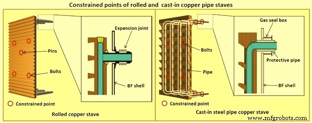
Fig 13 Constrained points of rolled and the cast-in pipe copper stave
Presently, the most popular type of copper stave is the rolled copper stave, the manufacturing process of which involves drilling holes on a copper plate. The water channel ends of these staves are plug-welded. The cast-in steel pipe copper stave, which has been developed, is made by casting bent steel pipes into the copper, a completely different manufacturing process from that of the conventional rolled copper stave. This unique manufacturing method has enabled achieving high energy efficiency and long life of BFs, which cannot be achieved using the rolled copper stave.
Natural evaporative stave cooling (NEVC) is a technique where boiler quality water is introduced into the bottom row of staves and flows by natural mean up the vertical cooling circuits. As the process heat conducts through the stave and cooling pipe into the water, the water in turn heats up. As the water warms, it expands. Since cooler water is being introduced below, the warm water tends to move upwards. At some point in the vertical cooling circuit, the water is at the boiling point. As the water changes its phase to steam, due to the latent heat of vapourization, additional heat is absorbed (driving the phase change). After boiling begins, two-phase flow (water and steam mixture) ascends the cooling pipes to the top of the furnace. Normally located on the furnace top platform are steam separator drums used to extract and vent the steam to atmosphere. Make-up water is introduced to the drum (to replace the discharged steam). The water is piped back by gravity to the furnace bottom and is fed once more to the staves. This cooling technique is very efficient and has low operating costs. There is no pumping equipment. The improvements in this system has been to boost the flow of the cooling water with recirculating pumps (forced evaporative cooling, FEVC) in order to ensure uniform cooling water flow and to cool the recirculating water (forced cold water cooling – FCWC). Both of these approaches have resulted in improved stave and lining life.
Staves provide an excellent protection for the shell plate throughout their service life (which is extended while the interior brick lining remains in place). Stave application has been implemented in all areas of the furnace from hearth wall up to and including the upper stack.
One drawback for conversion of an existing plate cooled furnace to stave cooling can be the cost of a new shell. However, if the existing shell is already in distress and is to be replaced in any event, the conversion cost is not a major factor.
Cast house
The cast house (Fig 14) is the area or areas at the BF where equipment is placed to safely extract the hot metal and liquid slag from the furnace, separate them, and direct them to the appropriate handling equipment or facilities. The hot metal and liquid slag are removed from the furnace through the tap hole. Only infrequently today slag is flushed from the slag notch. The equipment for tap hole is to be reliable and need minimum maintenance. Furnaces typically tap eight times to eleven times per day.
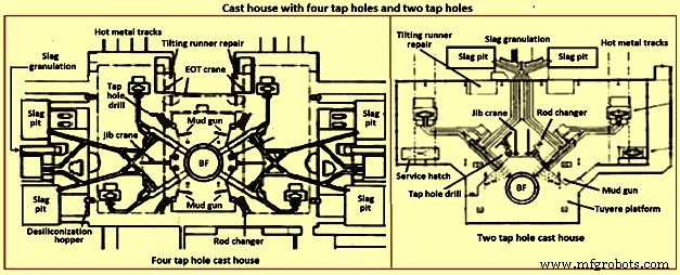
Fig 14 Cast house with four tap holes and two tap holes
Mud gun – The mud gun is used to close the tap hole after tapping is complete. A quantity of the tap hole mass is pushed by the mud gun to fill the worn hole and to maintain a quantity of the tap hole mass (the mushroom) within the hearth. The mud gun is normally held in place on the tap hole until the tap hole mass cures and the tap hole is securely plugged. A hydraulic mud gun uses hydraulic power to swing, hold, and push the tap hole mass. Typical injection pressure of tap hole mass is of the order of 20 MPa to 25 MPa, permitting it to push viscous mass into the furnace operating at high pressures. The hydraulic gun is held against the furnace with the equivalent of 15 tons to 35 tons of force. This type of mud gun can be swung into place in one motion.
An electro-mechanical gun has three separate electric drives for unit swing, barrel positioning, and ramming. Hence several separate motions are needed for accurate positioning of the mud gun at the tap hole. Tap hole mass injection pressure is in the range of only 5 MPa to 8 MPa. The electro-mechanical mud gun is latched to the furnace to keep it in place during plugging.
Tap hole drill – Tap hole drill is used to bore a hole though the tap hole clay into the hearth of the furnace. A drill unit is swung into place hydraulically and held hydraulically in the working position. A pneumatic motor feeds the hammer drill unit (with an attached drill rod and bit) into the hole. Compressed air is fed down the centre of the drill rod and the drill bit to cool the bit and blowout the removed tap hole mass. When the tap hole drill rod has penetrated into the hearth, the drill rod is retracted and the drill swings clear of the hot metal stream.
Soaking bar technique – The application of the soaking bar practice has improved the tapping process. When the tap hole mass is still pliable after plugging, a steel bar is driven into the tap hole by the tap hole drill. While the bar sits in place during the time between casts, it heats up by conduction from the hearth hot metal. This permits curing of the tap hole mass along its entire length (as opposed to curing with the furnace and setting at the outside near the furnace cooling elements). The cured tap hole mass is more resistant to erosion during tapping, hence improving tap flow rate control. Less tap hole mass is needed to replug the hole. When the tap hole is to be opened, a clamping device and a back hammering device on the tap hole drill extract the rod. The timing for tap hole opening can be more easily controlled (predicted) than by conventional drilling. This feature is important for smooth furnace operation and for scheduling of hot metal delivery to downstream facilities.
Same side tap hole equipment – Mud gun and drills have normally been installed on opposite sides of the tap hole. Design development has permitted installation of these equipments on one side of the tap hole. The drill swings over the mud gun or vice versa. This type of installation facilitates improved access for tap hole and trough maintenance and the improved application of trough and tap hole area flue collection.
With the advent of tuyere access platforms to facilitate tuyere and tuyere stock inspection and replacement, the headroom available for the tap hole equipment has diminished. However, same side tap hole equipment installations can be achieved with low headroom (for example 2.2 metres).
Trough and runner system – Typical hot metal and slag tapping rates are in the range of 4 to 6 tons per minute and 3 to 5 tons per minute, respectively. The trough and runner systems are to be designed to properly separate the iron and slag and to convey them away from the furnace for flow rates within the normal flow rate range and for unusual peak flow rates.
The hot metal trough (Fig 15) is a refractory lined tundish located in the cast house floor and designed to collect iron and slag after discharge from the furnace. The hot metal flows down the trough, under a skimmer and over a dam into the hot metal runner system. The hot metal level in the trough is dictated by the dam. Proper dam design submerges the lowest portion of the skimmer in the hot metal pool. The slag, being lighter than the hot metal, floats down the trough on top of the hot metal pool. Since it cannot sink into the hot metal and through the skimmer opening, it pools on top of the hot metal until sufficient volume collects to overflow a slag dam and run down the slag runner. At the end of the tapping, the slag runner dam height is lowered to drain off most of the slag. The residual hot metal is retained in the trough to prevent oxidation and thermal shock of the trough refractory lining.
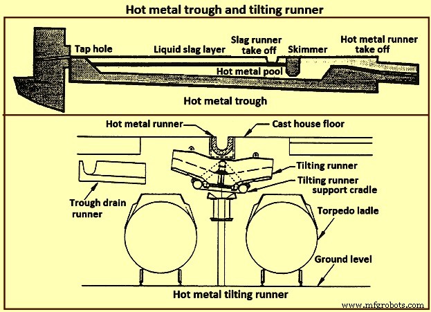
Fig 15 Hot metal trough and tilting runner
When maintenance of the trough lining is needed, the hot metal pool can be dumped by removing the hot metal dam, or by opening a trough drain gate, or by drilling into the side of the trough (at its lowest point) with a drain drill. The trough bottom is normally designed with a 2 % (minimum) slope for effective draining. Trough cross-section and length design are important for effective iron and slag flow pattern, retention, and separation. A good trough design results in hot metal yield improvements. Effective trough lining and cooling techniques are important for lining life, hot metal temperature, and cast house structural steel and concrete heat protection considerations. Troughs traditionally were contained in steel boxes ‘buried in sand’ in the cast house floor system. Improved trough design incorporates forced or natural air convection or water-cooling.
Cast house practice needs the runners to be as short as possible. This minimizes temperature loss of hot metal and reduces runner maintenance and flue generation. Shorter runners can also result in reduced capital expenditure for cast house building installation or modification. Since the runners are to slope away from the furnace, the cast house floor normally follows the same slope as the runners.
Slag runners are normally designed with a 7 % (minimum) slope. Slag can be directed to (i) slag pots for railway or mobile equipment haulage to a remote site for dumping, (ii) slag pits adjacent to the furnace for air cooling and water quenching prior to excavation by mobile equipment, and (iii) granulation facilities adjacent to the furnace for conversion of the liquid slag to granulated slag. Granulation units are provided with systems to eliminate flue emissions associated with environmental issues.
Hot metal runners are normally designed with a 3 % (minimum) slope. Hot metal is normally directed to hot metal transfer ladles (torpedo cars / open top ladles) for movement to the steel melting shop or pig casting machines. While normal practice used is to have one iron runner system with diverter gates directing the hot metal to different pouring positions, each with a ladle. Application of the tilting runner practice has been beneficial. A tilting runner is normally with an electrical motor-driven actuator (with a manual hand wheel back-up), and is tilted at around 5 degrees to divert the hot metal. A pool of hot metal is held in the tilting runner to minimize splashing and refractory wear. When one hot metal ladle has been filled, the runner is tilted to the opposite side to fill the other ladle. If needed, a locomotive removes the filled ladle and spots an empty ladle in its place. This operation can be done without plugging the furnace. When the tapping is finished, the tilting runner is tilted an additional 5 degrees to dump its pool of hot metal into the ladle.
Modern cast house design includes flat floors, where the runner is fully covered and is fitted flush with the floor. This allows safer and easier use of mobile vehicles in the cast house area. The use of radio controlled equipment and other devices have helped to reform cast house work, and these, along with effective emission control systems, have improved working conditions. As the BF hearth diameter is increased, there is a resulting need to increase the size of the cast-house. Large BF are normally designed with four tap holes (Fig 14). With a four top-hole configuration, the cast-house arrangement needs to provide sufficient space for movement around the floor itself. There is no design issues associated with this requirement as long as there is the necessary space provided in the site plan. Increasing the size of the cast-house in terms of floor plan does not represent a radical change in design philosophy which can pose a challenge the furnace designer. An efficient and strictly controlled tapping is necessary for ensuring a stable operation and high productivity of the BF.
Emission control
Fume collection requirements and applications appear to vary considerably around the globe. BFs presently have full, partial, or even no cast house fume collection system. Exhaust fan and bag house capacity of the order of 9,000 cubic meter per minute (cum/min) to 11,500 cum/min (depending upon operation and design practices) is typical for full flue capture of a two tap hole cast house installation (for trough runners and tilting runners).
Proper design and application of flue collection runner covers can facilitate cast house access (i.e. flat floor configuration using steel slabs or plates) for personnel and mobile equipment crossover. Runner covers can also reduce hot metal temperature loss and improve runner refractory longevity.
Some furnaces use flame suppression which eliminates the oxygen in the air directly over the trough and iron runners. Products of combustion prevent oxidation of the hot metal surface reducing visible particulate and flues.
Other aspects of BF design
It is necessary that complete study of every element in the process chain, from raw materials delivery to hot metal consumption is made to ensure that there are no ‘bottle necks’ in the system which can prevent the furnace from meeting the goals of its installation. While designing the BF, thought process is to be used to develop the furnace design and some alternatives are to be considered before freezing the design. During the designing of the furnace, those furnace equipments are to be selected which best meet the needs of the furnace operation.
The furnace design is to ensure (i) the furnace is capable of meeting the operational goals of production, productivity (tons per day per cubic metre of working volume), specific consumptions (kilograms per ton of hot metal), and product quality in cost effective manner, (ii) the furnace has the flexibility to accept and absorb the changes in the quality of the raw materials, and (iii) the furnace is capable of achieving the desired campaign life both with respect to time and the total production.
Financial justification is the over-riding consideration for the design. For this purpose, the economic study is to be very extensive. Further, the furnace design is to include latest technological developments so that the furnace does not become technologically outdated during its entire campaign.
The working volume of the furnace is the internal volume of the furnace calculated between the tuyeres and the stock line. Hearth productivity of the furnace is rated in tons per day per cubic metre of active hearth volume. Active hearth volume is the internal volume of the furnace calculated between the tuyeres and the tap hole. Active hearth volume is a measure of the holding capacity of the furnace for the liquids produced in the working volume (above the tuyeres). Hence, the tons per day per cubic metre of active hearth volume is a measure of the specific capacity (through-put per unit volume) of the hearth of the BF.
The design of the hearth is very important since it has a strong effect on the furnace operation. The furnace operation gets affected since the hearth liquid levels change rapidly which cause variations in gas flow pattern, gas utilization, and blast pressure. Also, because of these rapid changes in liquid level, there can be jamming / burning of the tuyeres which affect the blowing of the furnace.
The furnace hearth volume also determines the controls the operator is to exercise during furnace operation. For a very good hearth liquid level control, the high through-put furnace need around 90 % time spent in tapping. To make this time of tapping possible, cast floor is to be designed properly.
The furnace lining and cooling system needs special attention so that it does not pose any problem during the entire campaign of the BF. The selection of refractories, cooling elements, and internal furnace geometry is very important in this respect. Copper staves in this respect are expensive but they are very economical in comparison to the alternatives. Carbon lining of the hearth is very important for the long life of the hearth. The refractory lining thickness of the stack has implication on the furnace working volume.
The production needed normally determines the size of the BF. However, for the sizing of the BF, the raw materials, the product chemistry, and even operating philosophy are important. While the furnace size has implication on the capital cost, the productivity improvement has implication on the operating cost. The specific productivity of the furnace is to be determined for the determination of the size of the BF needed to produce the required quantity of hot metal. From the wide range of possible operating rates, the working volume of the furnace is to be calculated. Productivity and hence the furnace size is also to be based on the fuel rate. The fuel rate is dependent on the quality of raw materials, hot blast parameters, hot metal quality, and the operating philosophy.
The size is the most important factor for the determination of the BF productivity. However, there are other factors which also influence the BF productivity. The most important of these factors include (i) hot blast temperature and pressure, (ii) high top pressure, (iii) oxygen enrichment of the air blast, (iv) injection of auxiliary fuel at the tuyere, (v) prepared burden (sinter, pellets etc.), (vi) Fe content of the ferrous burden, (vii) ash in coke, (viii) quality of the coke, (ix) moisture content of the burden, (x) direct charging of fluxes (lime stone, dolomite etc.) in the BF, (xi) content of fines in the burden, (xii) quality of hot metal to be produced, (xiii) burden distribution control in the furnace, and (xiv) level of automation and control in the furnace.
The availability of furnace equipment, provision of stand-by equipment, and the maintenance philosophy are important factors which have high influence on the annual production from the BF. Further, incorporation of safe and healthy working practices during the operation of BF in the design of the BF is important which has a high influence on the furnace productions. In this regards, safety interlocks are to be provided at all the places where there exist a chance of unsafe operating practices to take place.
製造プロセス