


高炉負荷の準備と充電
高炉負荷の準備と充電
高炉(BF)は、炉床を除いて、基本的にはBF内を向流方向に移動するガスと負荷粒子の通路です。 BFを安定して運転するための基本的な要件は、炉内であまり変動しない移動層の負荷を維持することです。具体的には、安定したガス流と混合負荷層のない負荷層構造を形成することです。これらは互いに密接に関連しています。ガス流の安定性は、ほぼ完全に、負荷充填構造(粒子サイズ、粒子サイズ分布、微粒子比など)によって決定される負荷透過性と、固体の流れである負荷降下挙動に依存します。
原則として、BF処理は、固体、気体、液体、および粉末で構成される複雑な向流、並流、および/または交差流の4相流システムです。相の相互作用は明確であり、BFのさまざまな領域に局在しています。通常、BFには5つの異なるゾーン(図1)があります。つまり、(i)ゴツゴツゾーン、(ii)凝集ゾーン、(iii)コークスアクティブゾーン、(iv)燃焼ゾーン(レースウェイ)、および(v)デッドマンゾーン(炉床中央部)。 BFの特定の領域での負荷フェーズの違いと独特の相互作用により、BFのボリューム全体に単一の負荷の動きや流れのパターンはありません。
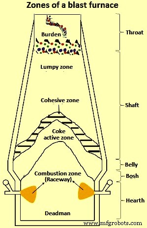
図1高炉のゾーン
BFには一般に4つの異なるタイプの固体流動領域があります。これらは、(i)負荷の均一な速度に関連するプラグフロー領域であり、ストックラインから下降し、凝集ゾーンまたは溶融ゾーンのすぐ上に位置します。(ii)部分的に不連続な塊である停滞フロー領域(デッドマン)炉床の中央部にある反応したコークス粒子、(iii)部分的に反応したコークス粒子の動きが遅いデッドマンに隣接する部分的に停滞した流れ領域、および(iv)周囲にある収束する流れ領域停滞ゾーン-炉壁距離内で粒子速度が大幅に変動するレースウェイ。
鉱石とコークスの反応、溶融、燃焼による鉱石とコークスの消失、鉱石層の上部と炉壁近くでの鉱石粒子の動き、および細粒原料の粗粒層等BFで下降する負荷に影響を与える要因には、原料の状態(粒子サイズ、強度、負荷分布-鉱石/コークス比)、軌道状態(補助燃料注入)、および炉が含まれます。内壁プロファイルなど
BF操作は、プロファイリング、粒子サイズ分布、およびパフォーマンスと生産性に影響を与えるすべての要因に非常に敏感です。 BFの円滑な運用を確保するためには、ストックラインでの固形物(鉄鉱石、コークス、フラックス)の分布を最適化することが不可欠です。ストックラインレベルでの負担配分を適切に制御することにより、BFの内部状態を制御することが重要です。
BFの負担材料は、スムーズなBF操作に必要な特定の要件を満たすことです。それは、機械的、化学的および熱的要件を満たすことです。帯電した材料は、負荷を支え、BFシャフト内の還元ガスの通過を可能にする強力で透過性の構造を形成するためのものです。微粉の形成がシャフト内のガス流の減少を妨げ、それによってプロセス効率を低下させるため、負荷の早期崩壊は回避されるべきである。したがって、BFでの細かい負担の材料の充電は排除されます。
生産性を最大化し、安定した炉の運転を確保するために、ゾーン内の負荷の下方への移動、化学反応、熱プロファイル、および液体の移動を最適化する必要があります。炉内プロセスと、原材料の物理的および化学的特性や粒子分布の徹底的な制御などの周辺操作の両方を最適化することにより、安定した高BF生産性操作の達成を実現できます。炉内プロセス(チャージされた材料の物理的変化と化学反応)と周辺補助操作(負担の備蓄、再生、輸送、保管、排出、運搬、チャージ)の両方が重複する機能であり、処理できないBFプロセスの円滑な機能を実現します。リンクされたプロセスであるため、分離されています。
BFチャージ材料、すなわち鉄鉱石、コークス、およびフラックスは、互いに接触している個別の固体粒子に類似しているため、バルク固体として分類されます。他の粒状材料と同様に、これらの材料は相互作用する粒子でできています。一般的に、これらの材料の内部構造は非常に進化しています。表1に示されているバルク固体材料の分類によれば、BFの帯電材料は、壊れた/不連続な固体としてバルクに分類されます。
| タブ1バルク固体のサイズ分類の定性的用語 | |||
| Sl。No. | サイズ範囲(mm) | 一般的な用語 | |
| 1 | |||
| 2 | |||
| 3 | |||
| 4 | |||
一般に、あらゆる形態のバルク固体の取り扱いには、均質性の維持という点で課題があります。バルク固体の個別の成分と同じ物理的および化学的特性の粒子を考慮すると、バルク固体の混合(意図的または非意図的)は必然的に成分の自然な分配をもたらすことが示されています。この概念は、一般に分離(デミキシング)として知られています。当然のことながら、および/または工業的に、バルク固体の個別の成分間の分離は、製品の意図された機能またはサブユニット操作に応じて、有益(例:物理的分離プロセス)または有害(例:混合プロセス)のいずれかになります。
>負担マテリアルハンドリングの理論的側面
BF負荷材料は、コークス、石灰華、ペレット、校正済み塊鉱石(CLO)、石灰石、ドロマイト、マンガン鉱石、および珪岩で構成されています。プロセスの性質上、BFプロセスは基本的に、負荷材料のサイズ、分布、および強度に敏感です。 BF内の負担物質の分布は、プロセスの化学的性質、プロセスのさまざまなフェーズ間の熱および物質移動だけでなく、ガスフローアップの動きにも影響を与えます。材料が下降するにつれて荷重が増加するため、材料の強度は非常に重要です。負荷の完全性は、高温高圧で発生する後続の化学反応によってさらに損なわれます。この化学反応では、摩耗や破損が一般的です。
BFコークスは、部分的な溶解反応でBFの炉床に降下する唯一の負担材料であるため、BF操作中の支持構造材料として機能します。これは、溶銑(HM)の製造コストの大部分を占めます。近年、コークスを安価な代替炭素源に置き換える動きがあります。通常使用される代替手段は、一般に微粉炭噴射(PCI)として知られているプロセスでのレースウェイへの石炭の直接噴射です。ただし、適切なコークスがないBFは、負荷の透過性が低下するため、交換の範囲には理論上の制限があります。これは、炉の詰まりや吊り下げにつながる位置であり、さらに炉のスリップが発生するシナリオです。
BF負荷の組成は、溶融温度、軟化、およびいくつかの還元パラメータなどの炉内プロセス変数を決定します。これは、負荷分布が最適化されていない場合、生産に悪影響を及ぼします。このような制限と課題があるため、負担の分散を適切に制御する必要があります。 BF負担材料の典型的なサイズ範囲を表2に示します。
| タブ2BF負担材料の一般的なサイズ範囲 | |||
| Sl。No. | 材料コンポーネント | サイズ(mm) | |
| 1 | 25 | 50 | |
| 2 | 10 | 30 | |
| 3 | 5 | 30 | |
| 4 | 8 | 20 | |
| 5 | 10 | 40 | |
| 6 | 10 | 40 | |
| 7 | 10 | 40 | |
| 8 | 10 | 40 | |
| 9 | 10 | 25 | |
BF電荷材料を含む粒状流の物理現象と流れ構造は、最初の考察では単純に見えますが、実際には、理解と予測が難しい複雑な挙動を示します。このようなプロセスの混合および分離パラメータに関する直接的な情報が不足しているため、状況はさらに複雑になっています。しかし、BFチャージ材料の骨材のサイズと材料サイズの分布が大きいため、分離傾向は深刻な運用上の問題であり、可能な限り削減する必要があります。
バルクマテリアルハンドリングと流動挙動
粉末力学の要素が19世紀半ばまでさかのぼって長い間知られているという事実にもかかわらず、バルク材料の挙動と流れの基本的な理解は不十分なままです。これは主に、流れの物理学の独特で複雑な特性に起因します。バルク材料の取り扱いは興味深い振る舞いを示しています。 1つの側面は、個々の粒子の特性により、粒子の巨視的な混合物が分離する能力です。これらの観察結果は、主にこれらの材料がパターンの発達と自己組織化を行う自然な傾向の結果です。この現象は主に、流体のような特性に似たバルク材料の挙動から生じています。
バルク材料が流体のような特性に似ており、それ自体が固体に似ている限り、全体的な動作と特性は、これらの一般的な物質の形態での観察と完全に並行しています。通常、ダイナミクスが常温の影響を受ける他の形態の物質とは異なり、バルク材料のダイナミクスではその影響は無視できます。流体に典型的な混沌とした移流または混合効果の競合が、バルク材料で観察される自己組織化傾向の原因であるのに対し、流れによって引き起こされる分離には流体現象がないことを知っておくと役立ちます。
基本的なプロセスのマクロな振る舞いは、主にミクロの粒子間接触と摩擦力によって支配されます。 5 mmを超えるBF電荷材料のサイズを考慮すると、表面力、つまり静電、ファンデルワールス、および毛細管効果の影響は無視できます。さらに、凝集傾向は粒子サイズが10マイクロメートル未満の超微細または超微細粉末材料に典型的であるため、負担材料の流動挙動は非凝集性固体に対応します。
バルクマテリアルフローの分類
バルク材料の流れは、その成分に従って分類できます。成分は、粒子のサイズ、密度、形状などの同じ物理的特性を持つ粒子のグループとして定義できます。流れの構造は分析が難しいことが多く、粒子間の相互作用、外部励起、境界条件の影響を大きく受けます。結果として、すべてのバルク材料の流れ構造を完全に記述するための包括的で一般的な方法はありません。粒子が接触している時間のセグメントに応じて、いくつかの異なるタイプの区別された流れ構造を確立することができます。
バルクロジスティクスフローの場合、粒状フローはさまざまな数の準安定非定常状態を示します。これらの準安定非定常状態は、振動などの外乱がなければ無期限に持続します。このような状態の維持は、粒子と境界が接触している時間のセグメントに大きく依存します。これは、流体(気体または液体)の総体積に対する固体の体積分率に依存します。結果として、粒状材料の流れは、一般に、固体の体積分率に応じて、希薄または高密度(接触が支配的)に分類されます。接触している時間のセグメントに応じて、高密度の流れは、衝突が支配的または接触が支配的のいずれかにサブカテゴリ化できます。これらの3つの分類では、動作と特性フローは特定の分類に固有です。流体と粒子の相互作用(つまり、揚力と抗力)は、希薄な流れでの粒子の動きを支配しますが、粒子間の衝突または粒子間の衝突、または粒子間の連続的な接触は、高密度の流れを支配します。
希薄流、衝突が支配的な高密度流、および接触が支配的な高密度流の間のバルク材料分類の概略図を図2に示します。図2に示されている希薄バルク材料分類は、サイクロンセパレーター、流動床、およびBF材料ホッパーで観察できます。それぞれ流れます。高密度(衝突および接触が支配的な)フローは、排出、保管、および輸送プロセス中のBFバルク材料に典型的です。
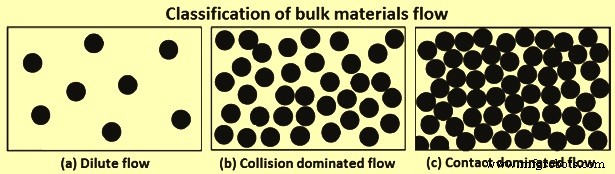
図2バルクマテリアルフローの分類
高密度マテリアルフローの2つの分類
2つの高密度フローレジームに共通する特徴は、長さと時間スケールの関数としての構造的進行です。通常、これは粒子の再配向によるパターン形成につながります。このような材料の配向は、中間規模の構造によって推進されます。マイクロスケールとしてよく知られている個々の粒子スケールは、中間スケールによってマクロまたは連続体スケールから分離されています。粒状フローアセンブリの複雑な粒子の相互作用を理解することは、分離または分離現象を定量化する上で重要です。この点で、マクロ構造(バルク)の動作と基礎となるミクロ構造(ディスクリート)のダイナミクスとの関係を確立する必要があります。
衝突が支配的なフロー –衝突が支配的な流れでは、流れは分散し、散乱し、エネルギッシュになり、粒子は主にほぼ瞬間的な2進衝突によって相互作用します。慣性効果は無視できます。衝突は非弾性であり、エネルギーは粒子間または粒子間相互作用中に散逸します。衝突は散逸的であるため、粒状材料の「流動性」を維持するために、ある程度の作業が必要になります。衝突の散逸性により、クラスター化や密度波などの特徴的な流れの挙動やパターンが観察されます。密度波は、粒子が均一に流れるのではなく、平均速度とは異なる速度の領域に粒子が流れる、粒状温度に関連する現象です。
連絡先が支配的なフロー –接触が支配的な流れでは、粒子間の衝突は強く相関しており、2値でも瞬間でもありませんが、永続的で複数です。この流れは、それを下回ると流れが可能になる臨界せん断応力と、流れが始まるときのせん断速度への複雑な依存性がある2つの興味深い特徴的なシナリオを示しています。このような依存関係の結果として、完全な流れ構造には、接触が支配的な流れに関連する粘塑性の特徴を含める必要があります。
さまざまな処理に基づいて提案されたいくつかの構成法則と、局所回転による自由度の追加、確率論的流れ規則の導入、粘性項、衝突頻度、散逸項などの運動理論輸送係数の変更などのいくつかの考慮事項があります。慣性数と呼ばれるパラメータがロバストな定式化であるように見える最近の定式化は、接触が支配的な流れの広範囲の粘塑性特性を再現することができます。慣性数は、せん断速度に粒子質量の平方根を乗じて圧力で割ったものです。
粉粒体の混合と分離
粒状材料の取り扱いは、特に材料のサイズが大きく異なる場合、分離(分離)する自然な傾向のために均一性と均一性の分布が必要な場合は特に非常に複雑です。混合が均一性を促進する流体プロセスとは異なり、粒状の流れは、長期の混合傾向が分離(分離)を促進する混合および分離の鏡像に似ています。このように、繰り返しの取り扱いプロセスを経るBF負担材料の場合、混合をサイレント機能として扱うと便利です。
粒状材料の自然な秩序は、均一な挙動からの分離または逸脱です。粒状物質がさらされるシステムの状態(充電、保管、排出、輸送)に応じて、分離が発生するメカニズムにはさまざまな形態があります。分離の主な要因は、粒子サイズの違い、密度の違い、および摩擦効果、反発係数、安息角などの微小特性の違いです。これらの要因の中で、粒子サイズは、粒状粒子の分離挙動を決定する最も重要な要因のようです。
粉粒体の分離メカニズム
偏析を最小限に抑えるための研究では、粒状物質の偏析の13のメカニズムが提案されています。ただし、これらのメカニズムのほとんどは、他のメカニズムの特殊なケースまたは重複するケースです。これを考慮し、柔軟性を持たせるために、分類粒状材料の分離は5つの主要なメカニズムに簡略化されています。これらの簡略化された5つのメカニズムでは、流動化と凝集の分離メカニズムはそれぞれ微粒子と凝集性粒子を指し、BFチャージ材料には適用できません。そのため、BFチャージ材料の充電、保管、排出、および輸送に適用できる残りの3つの主要な分離メカニズムを以下に説明します。
パーコレーションまたは動的ふるい分けメカニズム –サイズ分布範囲の粒子を相互作用させると(たとえば、材料貯蔵ビン内で)、小さな粒子が大きな部分の隙間を浸透して下向きにふるいにかけることで、自発的な固結の細流化が発生する可能性があります。当然、粉粒体が流れると粉粒体の隙間が広がり、隙間ができます。小さな粒子は大きな粒子の下の小さな隙間に押し込まれる可能性がありますが、その逆が発生する可能性ははるかに低く、自由表面から離れて、小さな粒子の正味の分離フラックスが下向きになります。このアクションは通常、パーコレーションとして知られています。定常状態では、粒子は多くの微粒子を含む最下層に分離します。パーコレーションメカニズムを図3に示します。粒子径d1とd2のバイナリシステムでは、d2がd1より大きい場合、d1/d2が0.1547以下のときに自発的なふるい分けが発生します。この臨界比の最初の使用は、パーコレーションメカニズムに基づくシュートフローの粒子サイズの違いによる分離の詳細なモデルを導出するために行われました。
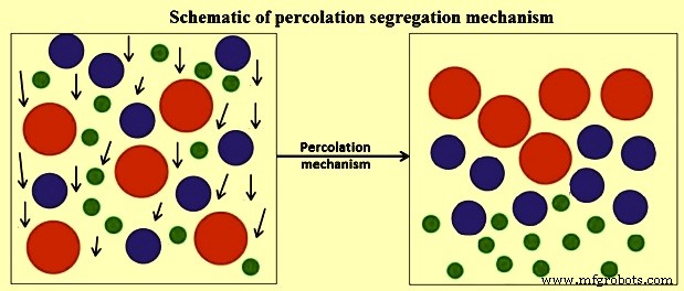
図3パーコレーション分離メカニズムの概略図
パーコレーション分離メカニズムは、大きなサイズで高密度の粒子が上部に移動する振動スクリーンなどの振動運動によるせん断誘導によって強化されます。これは、振動したシステムでの分離には幾何学的な考慮事項のみが必要であることを示唆しています。要するに、パーコレーション分離メカニズムが発生するためには、(i)ふるい分けのための臨界サイズ比、(ii)小さな粒子が隙間を通過するために非凝集性である必要がある、(iii)の3つの条件が主に満たされる必要があります。微粒子が複数の隙間に配向する可能性を高めるのに十分なひずみまたは粒子間運動の存在。
軌道メカニズム –軌道駆動の分離メカニズムは、通常、図4に示すように、主に貯蔵ビンに充填され、貯蔵ホッパーから排出され、コンベヤーベルトの端で排出される装入物移送ポイントで見られます。粒状材料の場合、異なるサイズの材料は、異なる摩擦抵抗のために異なる速度で移動し、材料の分離を引き起こすことが指摘されています。粒子が流体に水平に投射されることを考慮して、軌道分離のメカニズムが数学的に説明されています。ストークスの法則によって支配される直径d、密度Dp、および抗力の小さな粒子を考慮すると、初期投影速度Viで粒子が移動し、粘度Vf、密度Dfの流体に到達する最大距離Xが示されています。式X=Dp.Vi.(Dp)2/18Vfで与えられるとおりです。ただし、BF電荷材料のサイズを考慮し、抗力が無視できると仮定すると、粒子の軌道は無次元の軌道方程式で与えられます。無次元の軌道方程式はy/x =tan A – [g / 2(cos A)2]です。 x / Vi、ここでxとyはそれぞれ水平と垂直の空間座標、Aは傾斜角、gは重力による加速度、Viは自由飛行時の初速度です。方程式から、粒子の軌道はサイズ(質量)に依存せず、個々の粒子に関連する自由落下の開始時のランダムな速度であることがわかります。
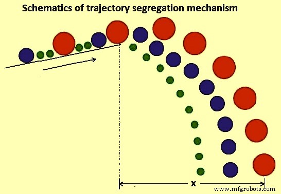
図4軌道分離メカニズムの概略図
マイクロプロパティの違いのメカニズム –このメカニズムでは、(i)摩擦効果、(ii)反発係数効果、(iii)安息角効果の3つの効果があります。
粒状材料に対する摩擦効果の研究は、静的摩擦係数Fが異なる2つの成分を持つ粒状材料が通常は分離することを示しています。研究中、高さhで質量m、すべり摩擦係数Fs、転がり摩擦係数Fr、半径rの球形粒子が、傾斜角Aの斜面で放出される場合を考えました。図5に示すように、エネルギーの保存の原則を考慮して、不安定な平衡状態にある粒子が、方程式m.g.sin A.r =m.g.cosA.Frで与えられる運動量方程式を満たす場合。この式では、粒子の移動距離Xは、式X =(h / Fs)。(Cos A)2。(1-Fs / tan A)およびX =(r.h / Fr)。(cos A)によって取得できます。 2.2。 (1- Fr / r.tan A)。これらの2つの方程式は、それぞれ滑り摩擦係数と転がり摩擦係数を考慮して、導出された粒子の移動距離を示します。これらの式から、転がり摩擦係数を考慮すると、粒子の移動距離は粒子の直径に依存し、これが偏析につながることがわかります。それどころか、滑り摩擦効果は、粒子サイズと質量の両方の独立性を示しています。
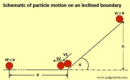
図5傾斜した境界での粒子運動の概略図
反発係数効果のメカニズムは、原則として動的効果です。粒子が衝突したり、粒子がシステムの境界に衝突したりすると、粒子はさまざまな速度で跳ね返り、最終的な位置は界面の弾力性によって決まります。メカニズムの例は、ヒープ上または貯蔵ビンへの粒子の充填です。ヒープの最上部に衝突すると、弾力性がほとんどないパーティクルは跳ね返らず、その位置にトラップされます。逆に、弾力性の高い粒子は跳ね返り、堆積スポットから離れた場所で最終的な位置を見つけ、ヒープの周辺に集中する可能性があります。
安息角効果の場合、粉粒体の積み重ね中に偏析のメカニズムが観察されます。ヒープを構築する場合、傾斜角(安息角)は材料の種類に依存し、粒子の数には依存しないことがわかります。回転ドラムの安息角に対する境界効果に関する研究では、軸方向の偏析は静的または動的な安息角のいずれかによって影響を受けることが指摘されています。原則として、安息角効果は、粒子サイズ、分布、形状、摩擦力などの材料パラメータに依存し、そのため、効果の他の変数が含まれるため、混合メカニズムになります。
粉粒体の分離の分類
粉粒体の分離は、検討中のプロセスで検討されている変数に基づいて分類されます。主に、(i)粒子の物理的特性(つまり、サイズ、密度、または形状の分離)、(ii)エネルギー入力(つまり、振動、重力、またはせん断の分離)、(iii)粒子の移動方向(つまり、水平)に基づいて分類されます。 、または垂直分離)、および(iv)使用される機器(ホッパー、シュート、またはコンベヤーなど)。
ただし、分離が作成されるメカニズムとしてよく知られている自然または確立されたプロセスは、最も一般的な分類アプローチのようです。偏析は表面現象と広く見なされています。そのため、観察されたさまざまなメカニズムは、表面層の下の粒子とは無関係です。原則として、メカニズムは、移動する表面層粒子の挙動を考慮することによってのみ説明することができます。さまざまなタイプの分離では、原則として、ほとんどの場合、全体的な分離メカニズムは、いくつかの相互作用するメカニズムの組み合わせです。たとえば、ふるい分けの分離は、パーコレーションと変位/移動の分離の特殊なケースと見なすことができます。これらは両方とも、大きな粒子に比べて小さな粒子がろ過されるという原理を共有しているためです。
分離の定量化
粉粒体の流れに対する偏析のメカニズムと影響についてはある程度理解されていますが、この現象から生じる問題は適切に制限されるべきですが、発生の回避から偏析の制御にシフトする必要があります。この点で、特に繰り返しの取り扱いプロセスを受けるBF負担物質の場合、影響を完全に理解して制御するには、正確な定性的および定量的分離測定方法が必要です。粒子分布の完全な説明は、そのような状況下での重要な演習です。ただし、炉のストックラインに正確に負担をかけるためには、粒子材料の分布に関する知識と、粒状流における混合と分離の定量化が不可欠です。
分離測定インデックス –原則として、分離は複雑な粒状材料の流れの一部です。さらに、粒状の流れが不透明であるため、分離研究中に有用なデータを物理的に抽出することは不可能ではないにしても、実際には困難です。理論的定式化を数学的モデリングシミュレーションに適切に組み込むことで、そのようなシステムの粒状流の混合と分離をより適切に特徴付けることが容易になります。分離の定量化は、分離を引き起こす要因と粒子の運動方程式との間の相互関係を完全に含めることを含むため、重要なタスクです。しかし、分離の定量的尺度として使用できる粒状混合の品質を測定するための多くの指標が提案されており、それらは一般に統計的用語または無次元数の用語で表されます。使用される一般的な混合および分離メトリックは、単一コンポーネントシステムのみを説明する相対標準偏差(RSD)です。このRSD分離メトリックは、システム全体の混合のマクロ混合状態を提供するため、反射型の産業用アプリケーションメトリックです。
混合および分離測定メトリックは、使用されている多くのインデックスのバックボーンです。混合および/または分離指数を定義するために、塊状のサンプルと特定の分散の測定値が使用されることを理解することが重要です。定量化は非常に有益ですが、そのような特性評価の主な欠点は、未発見のままである粒子間の分布の変動を無視しながら、測定領域全体で平均化することです。さらに、粒状材料の混合と分離について開発された古典的かつ基本的な概念では、粒状分離のプロセスが定義され、表面現象であると結論付けられています。
多くの研究により、さまざまな形状の処理装置、操作モード、および材料特性が、材料の混合および分離挙動に相関している可能性があることが示され、証明されています。まだ残っている主な課題は、混合ダイナミクスを説明するだけでなく、より複雑な分離現象に本質的に取り組む、統一された特性評価方法を使用することです。新しいアプローチは、時間と空間での混合と分離の程度を通知するために、充填システム内の原材料における粒子間の関係の進化を特徴づけることです。この方法の要点は、粒子とその最近傍との関係のいくつかの側面を使用して、進化する粒子ダイナミクスプロセスへの有用な洞察を推測できるという考えに基づいています。
粒状流の機械的分離モデル
分離動力学は、広く一般的に数理統計と確率の枠組みに組み込まれていることがわかっています。 The apparent limitation to this approach is that the absolute reflection of the physical nature of the process is precluded coupled with the failure to prescribe the direction in which segregation is taking place. This limits the possibility of a generalization since the knowledge is quite empirical. In the first pioneering study to develop mechanistic models which incorporate all the physics surrounding the prevalent de-mixing tendencies that occur in real granular flow system, the application of kinetic theories for mixtures of granular materials has been applied to study segregation tendencies based on percolation mechanism. Using a combination of statistical and dimensional analysis, the developed formulations hold for negligible enduring frictional contacts with shear rates sufficiently high so that the dominant contributions to the total stresses are due to particle to -particle and particle to boundary collisions. In this study, it has been observed that in a chute flow with high solids volume fractions, there is a high probability of small voids formation relative to big ones. The resulting effect of such a postulation is that small particles sieves through and collects at the base of the bed. This results in a net segregation flux in a direction normal to the chute surface of the small particles.
In as much as the mechanistic models described above give some intended physical appreciation in segregation description, evaluation of key fundamentals such as dispersion coefficients of such granular flows are not small and cannot be established by the above models. In this direction, one study suggested mixed statistical and mechanical interactions based on the kinetic theory of dense gas systems since they give a general understanding of causes of granular flow segregation.
Clustering occurs as granular flow experiences damping as energy is lost after collisions. The change in velocity and movement is non-uniform hence the clusters are formed. Hence, constitutive equations have been proposed based on a kinetic theory for collisional rapid flows. The utilization of the kinetic theory expressions for the analysis of granular segregation shows that it can be used only for inelastic and different sized particles at low volume fractions. This is a limitation as typical granular flow systems are contact-dominated flows with high solids volume fractions. The application of the theory is more useful in case there are established constitutive equations for inelastic, different sized particles and high solids volume fractions.
It is seen that the granular flow resembles mixing and segregation mirror image in which the prolonged mixing tendency promotes segregation. The concentration gradients results in mixing whereas the individual contributions of pressure and temperature gradients produce segregation in granular flow systems characterized by particles with particle size range distributions and material density differences.
The theoretical aspects of the bulk handling of the materials have given a general but compact back ground on granular flow, free surface segregation, mechanisms and theoretical approaches in granular material processes. BF burden material storage, handling and transportation processes are susceptible to the fate associated with segregation. For example, the BF sinter material is known to have more in-bin size segregation and more out of bin size variation than the BF coke.
BF charging system
The charging system of the BF iron-making process can generally be described as a network of equipment and mechanisms designed to charge materials into the BF in a certain sequence, quantity and at a rate which ensure that the specified furnace productivity and prescribed stock-line level is maintained. The charging system consists of three sub-systems which are essentially responsible for (i) batching (ii) transportation, and (iii) charging into the furnace respectively. Batching is done in the stock-house which receives the bulk solid feed materials from their various sources (stockpiles, sinter plant, and coke ovens), storing each material in individual bins to provide several hours of feed material for usual BF operations. The batching process includes screens, weigh-hoppers, conveyor belts, feeders and control systems to prepare batches of charge materials. Transportation provides the means for the delivery of the materials to the top of the furnace. Normally, this is done with either by the belt conveyor system or the skip hoist arrangement. The third sub-system consists of a network of equipment and mechanisms for the charging and control equipment. The overall charging system is interconnected and controlled by an automated charge programme.
Under some conditions, furnace productivity can be limited due to the capacity of the batching (stock-house) process to deliver charge materials. This occurrence is mainly due to transient charge materials flow, equipment settings and charge requirement (burden ratios). A typical source of transient change in charge composition is caused by changes in materials delivered to the stock-house bins and is usually referred to as ‘stock transitions’. This normally occurs when the reclaimed material is used such as the substitution of fresh coke and sinter with stored coke and stored sinter respectively. Such reclaimed materials are known to alter furnace performance compared with the fresh materials. Hence, there is need and usefulness of knowing the different materials and to have their accurate tracking through the charging system so that burdening and blast parameters can be controlled optimally to maintain furnace operational stability.
One other important feature of the charging system is the mixing and segregation of charge material. For example, accurate weighing of several materials in the same hopper requires sequential delivery of the material. However, when the weigh hopper discharges, the materials inherently intermingle to some extent, yielding a time-varying composition of the delivered stream. It is imperative to have an accuracy of time-varying composition in order to estimate the radial variation in burden chemistry and physical properties of the material delivered to the furnace.
Since the burden materials undergo multi-stage handling, hence the processing of different types of charge materials need greater control for high productivity and stable operation of the BF. Also, charge material batching and transportation phenomena are required to be the key focus area for BF operator. For smooth BF operation, the operator is to be position to accurately track the burden materials upto their delivery to the furnace charging system.
The overall charging system is interconnected and controlled by an automated charge program which is coordinated by discrete event processes. Previously, BFs were generally small compared to the modern-day large capacity BFs. In small furnaces, the theoretical amount of coke was normally determined as the controlling charging factor as such, with skip charged furnaces, the optimum charging capacity is reached with full skips of coke.
In the modern BF operations, over and above the need to cope with burden material requirements of larger BF capacity, there are two additional operational factors which are (i) sustenance, and (ii) environmentally friendly operations. Sustenance is mainly through the realization of high furnace productivity which currently has been achieved by an array of technology uses. With this added dimension, the total skip weight is now normally the controlling charging factor and thus modern furnace can work with full skips of iron-bearing burden component. Considering the large size of the present day BFs, the required skip capacities become extremely large and as a result, the design and installation of such skip charging facility to cater for such a huge continuously charging system pose a challenge. Such commensuration of modern large furnaces can only be achieved with sufficient burden delivery capacity. As a result, the modern furnaces are equipped with the conveyor belts charging system. The modern BFs charging facilities consist of a stock-house with a conveyor belt transportation of burden materials to the BF bell-less top (BLT) charging system.
BLT charging system
The charge material is conveyed to the BLT charging system where it is eventually charged into BF top material hoppers (bins) which are alternately used. While one hopper is being filled, the other one is being discharged. The operation of weigh-hoppers and material hoppers is essentially the same and thus, the further description gives an account of particle behaviour during conveyance (conveyor belt), intermediate storage (material bins and weigh hoppers) and eventual discharge (chute or free fall).
Conveyor belt particles behaviour – It is seen that the granular material of varying size fractions and density cause segregation. The detailed phenomenon of the transport mechanism of granular material on a conveyor belt remains limited. However, segregation phenomena on a conveying system are difficult to explain without elaborate simplification of the problem. The system under study has to be defined in terms of mass flow rate and the conveyor speed which promote particle bed development. Operative mechanism of segregation can be established only if the system is well defined. In Fig 6, a schematic representation of the particle size segregation at the transfer point of a moving conveyor belt is shown.
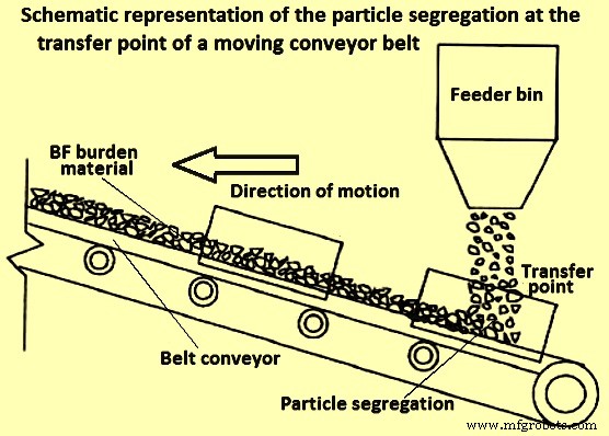
Fig 6 Schematic representation of the particle segregation at the transfer point of a moving conveyor belt
It has been established that there are four main mechanisms to be considered in conveyor belt material movement segregation namely (i) percolation, (ii) particle migration, (iii) trajectory, and (iv) free surface segregation.
Material bins and weigh-hoppers particles behaviour
Granular material bins and weigh hoppers are often used for storage and eventual discharge of material to the subsequent process step. They both in principle have (i) a form of defined material feeding or filling mechanism, (ii) some retention time of material, and (iii) a defined discharge region below. All the three steps have a contribution to the overall material flow behaviour at discharge. Physical and numerical simulations have been done to clarify the relevant information about particle segregation in different kind of hoppers namely cylindrical, bins, conical, and wedge-shaped. The desirable operation is a proportionate outflow from these devices. However, since the flow is gravity induced, the outflow is not easily controlled and there are an inherent induced shear and dynamic effects which cause segregation.
The main prevalent mechanisms of segregation in material storage bins and hoppers are free surface (during feeding), percolation (during retention) and trajectory (during discharging). There is also the importance of particle size and boundary geometry dimensions during the emptying and discharge phases.
In a study to investigate how the internal angle of hoppers affect the granular flow, it has been identified some significant hindrance to free-flow for cohesion-less solids using digital particle image velocimetry (PIV) measurements. As a rule of thumb, to avoid mechanical arching (particle interlocking), the ratio Do/dp (max) is to be satisfied in the range of 5 to 10. Here Do is the boundary outlet diameter and dp (max) is a suitable maximum particle diameter. The ratio is the dimensionless characteristic scale number and it is mostly influenced by the angle of repose as well as the particle size distribution of the material.
In another study, it has been suggested that at least eight elements are to fit across the total width of any granular material handling devices in order to capture accurately the material flow rheology. This means that the diameter of the largest particle fractions in physical or theoretical experimentation is to be at most an eighth the width of a hopper, conveyor belt or any other granular material handling device outlet.
Chute flow particles behaviour
Granular material chute flow is a common feature of stock-house and BLT charging system. With the BLT charging system which comprises of the charge receiving system, material hoppers and rotating chute (distributor), chute flow has assumed additional importance. However, the core principles of the chute flow in the BF top charging system are the same as the one in the stock-house.
Chute flow can be characterized by defining three steps which are (i) burden movement before the chute, (ii) on the chute, and (iii) after the chute, as shown schematically in Fig 7. These three steps constitute three different flow classifications and as such, different considerations need to be employed to study the flow behaviour in this system. When considering burden movement before the chute, any particle collisions in this region can be ignored due to the dilute nature of the flow. When burden material is on the chute, a mathematical description can be used with velocity component along the chute being used as the initial velocity of the material flow. At the chute tip, the trajectory of the materials determines the impact point which in turn the final scatter and distribution of the material in the subsequent handling boundary/ equipment. It is possible that the mechanisms of segregation postulated for conveyor belts systems also apply to chute flow as such and segregation shown schematically in Fig 7 is possible. Three flow streams can be identified with the core flow sandwiched between lower and surface flow. At this stage, the main force considered is gravity.
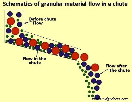
Fig 7 Schematic of granular material flow in a chute
The knowledge of segregation associated with charge material is useful for understanding the charge proportioning in addressing one of the aspects of BF process intensification. However, process intensification in BF processing requires an optimized charging system capacity as BF productivity can be limited by the capacity of stock-house to supply the charge. There is a need to address and optimize multiple-handling operation stages in the product chain.
Charging system capacity analysis
The operation of the BF charging system is as critical as the design of the BF. As can be seen in the schematic representation of a typical modern BF charging system equipped with a conveyor belt delivery system in Fig 8, the material flow sequence is quite complex.
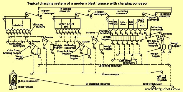
Fig 8 Typical charging system of a modern blast furnace with charging conveyor
In the interest of high productivity, the design of a BF charging system require attention to operating flexibility, availability of extra charging capability, high screening efficiency as well as a limited number of filling, discharge and transfer operations as these cause segregation problems. One important route to increase the efficiency of the BF is full utilization of the charging system capability. Further to this, if the stock-house is not adequately designed and optimal burden delivery is not achieved, the starvation of the BF take place due to the non-availability of the burden materials which consequently results into the loss of BF productivity.
As seen in Fig 8, there are numerous unit operations in a stock-house assembly and all of them have a cascading effect on the overall performance and output delivery to the BLT charging system. In order to understand the macro-behaviour of the burden movement and overall system performance, effective and comprehensive representation of salient system elements and their relationships are to be established. Technically, this involves a description of the various handling steps, materials requirements, duration and sequencing of operations. However, for complex systems such as the stock-house, it is a huge task to clarify all the unit process information. A blend of engineering judgement, experience from similar processes, and reasonable assumptions are used for model development input data and the stock house design.
Modelling of BF charging system optimization
BF charging system involves multiple-handling material movement. The major challenge associated with multiple-handling during materials movement is the timely fulfilling of the requirement and sudden change in the process. Simulations are often used to optimize materials handling systems. Such systems generally use computer-aided process design simulators. These simulators are generally designed to model transient and continuous processes and as such they cannot be used for BF charging system operations which is a batch and semi-continuous process at best. Two available options for modelling batch and semi-continuous processes like BF charging system are spreadsheets (Microsoft Excel) and discrete event simulation (DES).
Spreadsheet models are a common platform that focuses on material balances, equipment sizing and cost analysis. Typically, the development of such a model involves writing an extensive code (in the form of macros and subroutines) in visual basic for applications (VBA) which are incorporated in Microsoft Excel. They are easy to build, much applicable to simple systems but they lack robustness and become unwieldy for large and complex systems. DES is a mathematical/ logical model of a physical system which portrays state changes at precise points in simulated time. Both, the nature of the state change and the time at which the change occurs, mandate precise description. The main feature for a successful DES is an upfront requirement of precise details regarding system and interruptions. Typically, a DES can statistically account for downtime and events. Also, modules can be created and reused while multiple grades or change in process input can be easily handled. Hence, generally the DES-based model is normally used for the BF charging system.
Cyclograms analysis is a modest DES modelling technique which has been often used in BF charging systems for its optimization. The concept evolves on the minimization function of overall start – end sequence (delivery time) of a charging cycle. The delivery time is determined by the order of activation of the mechanisms, the duration of their sequence and the length of the intervals between individual operations. It is easy to follow that the minimum cycle duration occurs when the system is devoid of pauses between the operating cycles of individual mechanisms, as well as when the mechanisms are activated in an efficient sequence.
With cyclograms analysis, it is difficult to incorporate real-time changes in system input conditions. Furthermore, the structure of the analysis precludes detailed in-cooperation of micro-system variables such as discharge behaviour and segregation tendency of materials. Due to these weaknesses of the cyclograms analysis, a DES charge material delivery model based on a mathematical/ logical representation is the better choice for the BF stock house optimization
製造プロセス