


日本の高炉での製鉄と解剖研究を理解する
高炉での製鉄と日本の解剖研究の理解
高炉(BF)製鉄は、主にその十分に確立された実証済みの性能、柔軟な原材料使用、および高い熱エネルギー保存能力により、溶銑(HM)を製造するための最も実行可能な手段です。 BF製鉄の開始に利用できる決定的な日付はありません。しかし、重要なプロセス設計と再設計は、14世紀までヨーロッパの製鉄炉で実施され始めました。それ以来、BFルートは他の代替鉄生産方法よりも優先されるプロセスとして支配されてきました。
BF製鉄プロセスは、その開始以来、存続し、実行可能であり続けるために、非常に効率的なプロセスになるために永続的な進化の発展を遂げてきました。これまでの最も重要な開発には、(i)設備の近代化、(ii)炉の生産性の向上、(iii)コークス率の低下、(iv)炉のキャンペーン寿命の延長、(v)材料の柔軟性と改善が含まれます。経済性、効率を改善し、プロセスを環境に優しいものにするために実施された技術的進歩には、(i)さまざまなプロセス管理および制御慣行、(ii)センターコークスの充填、(iii)高炉トップ圧力操作、(iv)が含まれます。 )酸素(O2)濃縮による炉の運転、(v)高価なコークスの代替の補助炭素源、すなわち微粉炭、天然ガス、石油、プラスチックへの代替、および(vi)その他多数。 BF製鉄プロセスの技術開発により、小さな生産ユニットから大量の燃料を消費する現在の状態に至り、1日あたり10,000トンのHMを生産するように設計された炉がいくつかの国でかなり一般的になっています。 BFのサイズと出力がこのように劇的に増加したとしても、炉内で発生する反応の多くはまだわかっていません。
最新のBFは、主に、シンター、ペレット、シンター/サイズの鉄鉱石、またはシンター/ペレットの負荷で動作します。これらの材料の種類と品質は、個々のプラントの運用哲学に依存するため、これらの材料の生産と削減の特性は、BFプロセスにとって非常に重要です。
BFプロセスの開発
BFプロセスで行われた開発は徐々に導入され、最終的に標準的な運用方法になりました。 (i)準備された積荷の効果的な使用、(ii)爆風注入剤、(ii)高い上部圧力、(iv)高い爆風温度、および(v)改善された制御からなる、おおよその時系列で主要な進展をリストすることが可能です。負担配分の。これらの開発と同時に、BFの物理的サイズが徐々に大きくなっています。
準備された負担の使用
装入物の最初の準備は、単に炉に投入された鉄鉱石のサイジングでした。負荷のサイズを小さくすると、炉の透過性が向上し、より多くの風が吹くようになり、BFの出力が増加します。さらに、より大きな鉱石の塊が除去されたため、還元反応の効率も向上し、コークス率が低下しました。
装入前の鉄鉱石の焼結は、負担準備の2番目の重要なステップでしたが、焼結は元々、BF煙道ダスト、ミルスケール、鉱石微粉などの廃鉄含有材料を使用可能なBFフィードにするために開発されました。しかし、この概念は、1950年代半ばに自己フラックスシンターで成功を収めた後、急速に変化し、フラックスをBFチャージの負担から取り除き、シンターを通して導入できるようになりました。これはまた、BFの生産性を高めながらコークス率の低下につながりました。現在の状況では、シンターは現在、現代のBFプラントで確立された負担要素であり、その特性をさらに改善するために継続的な調査が行われています。
容易に入手できる高品位の鉄鉱石が枯渇したため、供給業者は、選鉱とそれに続く精鉱からの高品位の鉄鉱石ペレットの製造によって製品をアップグレードする必要がありました。このプロセスは広く受け入れられ、鉄含有量が高く脈石含有量が低いBF炉に負担がかかり、コークス率の低下と相まって生産量がさらに増加しました。ペレットで主張されているもう1つの改善点は、サイジングが近いために負担の透過性が向上したことです。ただし、ペレットの使用は普遍的ではなく、いくつかの国では、BFは主に、ペレットおよび/またはサイズの鉄鉱石が全体の料金のわずかな割合を占めるという、より厳しい負荷で運用されています。確かに、ペレットは転がりやすく、分配の制御が難しいため、焼結は高温と分配特性に優れているため、大きなBFの安定した動作には高い焼結比率が不可欠であるという見方もあります。また、BFで石灰華を使用しているため、コークス炉プラントで発生したコークス風は鉄鋼プラント内で消費されます。
ブラストインジェクタント
BFで通常使用されている3つの注射剤があります。これらは、(i)蒸気、(ii)O2、および(iii)補助燃料です。注入剤は火炎温度、つまり羽口の燃焼ゾーンの火炎温度に影響を与えます。蒸気と補助燃料は火炎温度を下げ、O2は火炎温度を上げます。理論的な火炎温度を計算することができ、大量のO2と補助燃料でスムーズな運転を維持し、生産性を高めるために非常に重要です。火炎温度が低いと、炉内での反応が妨げられ、炉の冷却につながります。火炎温度が高いと、溶融ゾーンが拡大し、負荷内のアルカリとシリカ(SiO2)が蒸発するため、透過性が損なわれる可能性があります。スムーズな操作を保証するために、注入剤の量を変えることによって理論的な火炎温度を制御する必要があります。
3つの注入剤を別々に見ると、蒸気はコークスと反応して水素(H2)を生成します。これにより、負担物質の削減の程度が高まり、燃料レートが低下します。補助燃料が主な噴射剤です。使用する補助燃料の種類は、地域の状況によって異なります。補助燃料の噴射により、BFに追加量のH2と一酸化炭素(CO)が供給され、負担の軽減度が高まり、コークス率が低下します。不完全燃焼は炉の透過性を損ない、炉の運転に悪影響を与える可能性があるため、羽口で補助燃料を完全に燃焼させることが不可欠です。不十分な燃焼は、爆風に十分な過剰のO2を供給することで制御できます。
酸素注入は過剰なO2の量を増加させ、火炎温度を上昇させます。これは、蒸気と補助燃料の注入によって引き起こされる火炎温度の低下を打ち消します。また、ボッシュガスの量を減らすのにも役立ちます。これにより、BFでのガスのチャネリングの程度、およびフラッディングと負荷の程度を最小限に抑えることができます。氾濫は不規則な炉の運転を引き起こします。負荷とは、ガスの速度が上向きであるために溶融スラグが下降しない状態です。最終的に、スラグの重量は、スラグが下降するためのガスの流れに打ち勝つために十分になることです。爆風中のO2の比率が徐々に増加すると、HM 1トンあたりに生成されるガスの量が減少し、ガスからシャフト内の固体への熱伝達量が低下し、その結果、シャフト。また、O2濃縮による生産性の向上により、負荷降下率が加速し、熱伝達にかかる時間が短縮されます。その結果、装入物は十分に予熱されずに高温ゾーンに入り、炉を冷却し、装入物が滑ったりぶら下がったりします。
注入剤の使用には、(i)ガスと固体間の熱伝達の制限、(ii)理論上の火炎温度の制限、および(iii)補助燃料の完全燃焼の制限という3つの制限に関して注意深い制御が必要です。これらの制限内で制御すると、燃料料金が低くなり、生産性が高くなります。
高いトッププレッシャー
高いトップ圧力の利点は、それが炉内のガス速度を低下させ、それによりガス還元のためのより多くの時間を可能にし、燃料速度の低下をもたらすことである。より低いガス速度はより粗いダスト粒子を運ぶのに不十分であるため、ダスト損失も減少します。あるいは、より多くの風を吹き付けることができるため、炉内で同じガス速度を維持しながら生産量を増やすことができるため、チャネリング、フラッディング、および負荷を防ぐことができます。主な欠点は、ガス圧の上昇に対応するために、ストーブからバッスルパイプ、炉壁、炉の上部、ガス洗浄プラントなどに至るまで、BF機器全体に頑丈な構造が必要であり、これは明らかに高価です。確かに、BFトップだけでも、チャージングシステムのガス圧を均一にし、ファーネストップチャージング装置の摩耗を防ぐために特別な設計が必要です。もう1つの欠点は、高圧上部ガスのエネルギーが失われることですが、上部ガス回収タービンはこのエネルギーの一部を回収できます。
工学的観点から高いトップ圧力の適用には問題がありますが、大型高炉の運転では、(i)燃料率を下げ、(ii)炉の生産性を高めるためにそれを使用する必要があります。
>高い爆風温度
羽口を通ってBFに入る空気は、コークスの燃焼によって加熱されます。したがって、流入する空気が高温になるほど、羽口領域内でさらに加熱する際に消費されるコークスは少なくなります。空気の予熱は新しいことではありません。実際、1世紀以上前、BFストーブが存在していました。しかし、1300℃を超える温度が達成されたのは比較的最近のことです。より高い温度の達成は、ストーブの設計の変更によるものです。これらの変更は、(i)レンガの形状を変更することにより、チェッカー作業の加熱面の面積を増やすこと、(ii)高温に耐えることができる高品質の耐火物を使用すること、および(iii)外部燃焼室を提供することです。加熱表面積が増加します。
負担配分の改善
ガス利用率を向上させ、燃料率を下げるためには、負担物の分配を管理することが重要です。 BFの凝集ゾーンの形状を制御して、生産を最大化し、BF壁でのガスの流れを最小化して、炉の寿命を延ばすには、正しい分布も必要です。
炉のサイズが大きくなると、BF内の安定したガス分配を提供するために必要な負荷材料の分配は、コンパイル角度、密度、および形状の違いにより、従来の充填装置では維持できなくなります。これらの問題は、充電ベルを離れる際の材料の分配を制御するための可動装甲の設置によって部分的に克服されました。炉のストックライン上の任意の位置に正確にチャージを分配できる回転シュートを備えたベルレストップおよびジンブルトップチャージングシステムの開発は、この問題の解決に大いに役立ちました。
>鉄鉱石シンター
多くのBFでは、焼結体がBFの負担の主要な要素です。焼結鉱の化学組成は、炉の負担を構成する他の成分に依存します。通常、焼結鉱はフラックス(CaO / SiO2約1.2)からスーパーフラックス(CaO / SiO2約1.7〜2.2)の範囲です。フラックス焼結体は、一般的に、炉の負担の大部分が焼結体である場合に使用されます。超フラックス焼結鉱は、残りの負担が本質的に酸性である場合に使用され、したがって、スラグの化学的性質のバランスを取り、許容可能なスラグ組成を提供します。焼結プロセスの性質上、焼結は非常に不均一です。
シンターの構造 –鉄鉱石と混合されるフラックスは、焼結中に反応し、鉱石粒子を溶かして攻撃します。小さな鉱石粒子の完全な凝集が発生する可能性がありますが、一般的に大きな粒子は表面攻撃を受けるだけです。冷却中、異なる相の沈殿がスラグマトリックス内で発生し、全体的な結果は、平衡状態から遠く離れた相と、その相が最初の混合における成分の分離に依存する不均一な材料の混合物になります。焼結前に石灰の粒子が存在していた場所では、石灰が豊富な領域が形成されます。全体として、存在する相は、添加されるフラックス剤の量に依存します。自己流動性の焼結鉱は主にヘマタイトとマグネタイトで、鉄鉱石と石灰の反応によって生成される少量のカルシウムフェライトが含まれています。ここで「フェライト」という用語は、反応ゾーンの塩基度と鉱石粒子に応じて、生成できるさまざまな種類のフェライトの合計量を指します。塩基度が高くなると、フェライトの割合が高くなります。
焼結鉱では、通常、フェライトはSiO2とAl2O3(アルミナ)で汚染されており、その製品はSFCA(カルシウムとアルミナのシリカフェライト)として知られています。 SFCAは通常、一般式「n1(Fe2O3).n2(SiO2).n3(Al2O3).5CaO」に準拠しています。ここで、n1、n2、およびn3の合計は約12です。カルシウム含有量は約15でかなり一定です。 %。実際には、通常、フェライトは7 Fe2O3.2SiO2.3AI2O3.5CaO、および9Fe2O3.2SiO2.0.5AI2O3.5CaOであることがわかります。
シンターの削減 –焼結鉱に存在するフェライトの種類と量は、還元特性に重要な役割を果たします。フェライトの還元性は一定ではありませんが、種類によって異なります。焼結塩基度が高くなるとフェライトの割合が増えることがわかります。ただし、削減可能性は同じ傾向には従いません。塩基度範囲1.0〜1.5の間では、CaO.2Fe2O3型とCaO.FeO.Fe203型のフェライトが増加するため、還元性が向上します。塩基度範囲1.4〜1.5では、焼結鉱に存在するヘマタイトの割合が低下し、CaO.2Fe203が消失し、比較的還元性の低い2CaO.Fe2O3が出現するため、還元性が低下します。 1.5を超える塩基度の増加は、CaO.Fe2O3およびCaO.FeO.Fe2O3の出現により再び上昇傾向を示しています。
フェライトの還元挙動は、酸化鉄の還元が起こるために分解するという点で複雑です。還元プロセスでは、最初に、酸化鉄が豊富な高次の酸化鉄とフェライトが、二カルシウムフェライトとウスタイトのみが残るまで還元されます。次に、ガスは、可逆反応2CaO.Fe2O3 + 3H2 =2CaO + 2Fe + 3H2Oに従って、二カルシウムフェライトを攻撃します。遊離したCaOは、可逆反応2CaO + 3FeO =2CaO.Fe2O3 + Feに従って、すぐにウスタイトと反応します。その後、反応は前の式のように進行します。ただし、顕微鏡写真は、ガス境界にウスタイトが存在しないため、2つの反応間の拡散プロセスが発生することを示しています。研究によると、酸化物表面では、二カルシウムフェライトが最初に還元されます。遊離した鉄は酸化物相で分離し、カルシウムはウスタイトに拡散して反応し、再び鉄は分離するか、Fe3O4に拡散します。
鉄鉱石ペレット
鉄鉱石ペレットの製造プロセス中に、鉄鉱石は、遊離した脈石材料を粉砕して除去することによって恩恵を受けます。一般に、ペレットの特性を改善するために、酸ペレットの製造にいくらかの石英が添加されます。生成されるペレットの大部分は酸タイプです。つまり、フラックスを意図的に実質的に追加する必要はありません。酸性ペレットの製造中、緑色のペレットは酸化性雰囲気中で約1300℃で焼成されます。これは、(i)ヘマタイト粒子の焼結、(ii)マグネタイト粒子の酸化とそれに続く焼結、および(iii)スラグ結合によって粒子の結合を促進します。後者は、緑色のペレットの十分な強度を確保するためにペレット化のプロセスで使用される、脈石とベントナイトの小さな痕跡の融合によって引き起こされます。このスラグ相は、本質的に石灰、シリカ、酸化鉄、および微量のアルカリ、マグネシア、アルミナなどで構成されています。
スラグ相の化学組成の指標は、CaO-SiO2-Fe2O3状態図を参照することで取得できます。注意すべき点は、大部分のプロセスでは反応が平衡状態になることはめったにないため、平衡状態図を注意深く使用する必要があることです。それでも、このような状態図は有用なツールです。焼成中に石英粒子とヘマタイトの間で反応が発生することはほとんどないため、酸ペレットはヘマタイト、石英、スラグ相で構成され、場合によっては、十分な焼成が行われなかった場合は、マグネタイトが発生します。ペレットブレンド中のマグネタイト鉱石。
酸ペレットは、炉の負荷の一部のBFで使用されます。負担に使用される金額は、採用された運用慣行によって異なります。鉄ユニットの供給源として完全に酸性ペレットで動作するBFの場合、スラグ形成プロセスに必要なフラックス(石灰石とドロマイト)は、負担の一部としてBFにチャージされます。
フラックスペレット –現在、フラックスペレットの使用が推奨されています。フラックスペレットでは、フラックスがペレットに組み込まれるため、別々に炉に充填する必要がありません。フラックスペレットは、フラックスまたはドロマイトとして石灰を添加して製造できます。フラックスの添加によりペレットの塩基度が増加するにつれて、微細構造に変化が生じます。石灰フラックスペレットを考慮すると、石灰の添加はスラグの組成と量、さらにはヘマタイトの量に影響を与えます。石灰を添加すると、ヘマタイトと石灰が反応して、石灰の濃度に応じてカルシウムフェライトCaO.Fe2O3または2CaO.Fe2O3が生成される可能性があります。フラックス入りペレットの場合、過剰なスラグの形成を避けるために、焼成温度は酸性ペレットの焼成温度よりも低くなります。
フラックス状のペレットの場合、石灰による化学反応により、カルシウムフェライトに囲まれたヘマタイトの粒子が見られることが期待されます。場合によっては、元のヘマタイト粒子がカルシウムフェライトに完全に変換されることがあります。これは明らかに元のヘマタイト粒子のサイズに依存します。スラグ相に対する石灰の影響は2つあります。第一に、スラグの量の一般的な増加があり、第二に、塩基度の変化があります。正確な組成は、当然、反応する相の量に依存しますが、CaO-Fe2O3-SiO2の状態図から可能性を推測できます。フラックスペレットの問題の1つは、還元特性が比較的低いことです。石灰フラックスペレットのこの欠点は、石灰の代わりにドロマイトでフラックスされたペレットの生産につながりました。
酸化鉄へのマグネシアの添加は、2つの間の固相反応と融解温度の上昇をもたらします。したがって、ドロマイトフラックスペレットでは、マグネシオフェライトMgO.Fe2O3または(Mg.Fe)O.Fe2O3が生成されます。マグネシアとシリカの間の溶融は焼成温度では発生せず、固体状態で発生する反応のみが発生する可能性があるため、石英はドロマイトフラックスペレットに完全に吸収されません。
酸ペレットに関連する還元メカニズムは、ガス還元、反応速度論、および直接還元によって説明できます。ガス状還元の場合、酸化鉄からO2が除去されると、酸ペレットは赤鉄鉱から磁鉄鉱、ウスタイト(560℃を超える温度)、金属鉄の還元経路をたどります。これらの相変化は、還元剤としてCOを使用する可逆的なガス反応によって表されます。方程式は、3Fe2O3 + CO =2Fe3O4 + CO2、Fe3O4 + CO =3FeO + CO2、Fe3O4 + 4CO =3Fe + 4CO2、およびFeO + CO =Fe+CO2です。
ヘマタイト還元のメカニズムは広く研究されており、ヘマタイトの還元は離散的なステップ、すなわちマグネタイト、次にウスタイトなどでは起こらないが、還元は上から下への化学構造を生成することが注目されている。ガスのポテンシャルは十分に高いです。つまり、構造はヘマタイト粒子で構成され、マグネタイトの層、次にウスタイト、最後に金属鉄の外層に囲まれています。ウスタイトは非化学量論的です。つまり、鉄イオンが不足しています。これらの空孔は、酸化鉄格子を介した鉄の拡散を可能にするため、酸化鉄の還元挙動における重要な欠陥です。ウスタイトからO2を除去すると、酸化物表面の鉄イオン空孔が埋められます。
表面還元は、酸化物の内部から反応界面に向かって空孔と電子欠陥の拡散を開始します。ウスタイトが減少すると、金属イオンの内向きの流れがマグネタイト層と反応し、マグネタイトが減少します。その後、反応が起こり、サイクルが繰り返されてマグネタイトが徐々に減少します。
酸化鉄の還元の動力学は広く研究されてきたが、速度制御ステップに関していくつかの相反する見解が存在する。酸化鉄のガス還元のプロセスは、(i)バルク気相から境界層を通る反応ガスの拡散、(ii)生成物層を介した反応界面へのガスの拡散、(iii)などの多くのステップを必要とする。反応界面へのガスの吸着、(iv)界面での化学反応、(v)反応界面からの生成物ガスの脱着、(vi)反応界面から粒子表面へのガス状反応生成物の拡散、 (vii)境界層を通ってバルク気相への生成ガスの拡散。
1つまたは複数の速度制限ステップに関しては大きな矛盾がありますが、一般に酸化鉄の還元は、McKewan K1 =Kw / do =ro [1 –(1- R1 / 3)]/tによって導出される式に準拠します。ここでK1は速度です。ヘマタイト/マグネタイト界面の前進(mm /分)、Kwは速度定数(g / sq mm /分)、do =純粋な酸化鉄球の密度(g / cu mm)、roは酸化鉄球の半径( mm、Rはヘマタイトからマグネタイトへの分別変換であり、tは分単位の反応時間です。酸化鉄の還元速度はこの方程式に準拠しているため、律速段階は化学反応であると主張されています。
Hillsは、物質移動の原理を使用して、物質移動と拡散のみによって制御される反応が、化学的に制御される反応、特に[1 –(1 – R)1/3)]の時間に対する線形性を識別するために頻繁に使用される特定の特性を持つことができることを示しました。 。 Hillsは、反応は(i)生成物層を介したガス拡散と(ii)粒子の外部の境界層を介した輸送の両方のプロセスによって制御されると仮定しました。ヒルズレート方程式の形式は、3 [1 –(1 – R)2/3]-2R(1- Bm)=C2.tとして表すことができます。ここで、Rは部分的な削減、tは秒単位の削減時間、Bmです。 =DE / Kg.ro、Bmは物質移動の係数、つまり製品層内の拡散抵抗と粒子外の物質移動抵抗の比率、DEは製品層の拡散係数(sq mm / sec、Kg)は反応する球の表面への物質移動係数(mm /秒)、roは球の半径(mm)です。 C2は還元反応の定数であり、酸化鉄球の特性と環境条件に依存します。
800℃以上の温度で還元する場合、粒子の溶融が起こらなければ、ガス状還元の温度が上昇すると反応速度が上昇します。気孔率の増加は、減少率の上昇ももたらします。
炭素(C)による酸化鉄の直接還元のメカニズムはBFで非常に重要であり、直接還元は900℃を超える温度でかなりの量でのみ発生することがわかっています。直接還元反応は実際には次のように分割できます。方程式FexOy+C =FexO(y-1)+CO。ガスによる還元はCO+ FexOy =FexO(y-1)+CO2です。これらの反応では、x =1、2、または3およびy =1、3、または4です。溶液損失(Boudouard)反応CO2 + C =2COは、ガス反応にCOを提供します。直接還元反応は実際には間接還元反応を介して発生するため、BFプロセスでの固体酸化物の直接還元は反応の進行に関して重要ではないことを示しています。
液体酸化物がCと反応する状況は、もちろん、液体酸化物と固体Cの接触面積が、固体酸化物と固体Cの接触面積よりもはるかに大きいという点で、まったく異なります。また、液体中の反応種と生成物種の拡散は次のようになります。固体状態よりもはるかに高速です。これらの効果により、液体酸化物/固体Cシステムでは、固体酸化物/固体Cシステムよりもはるかに高い反応速度が得られます。反応温度が高いほど、還元の程度は大きくなります。 FeOに富むスラグを還元するための律速段階は、還元の程度によって変化することが見出された。還元された鉄の核形成とC/液体界面での化学反応は、高度の還元が達成されるまで律速段階を構成するように見えます。より高い還元レベルでは、最も遅いステップはスラグ境界層を介したO2の拡散です。
還元時のアルカリの影響
アルカリは、高温ゾーンでの気化とそれに続く低温領域での負荷とコークスへの堆積によって、BF内で再循環します。堆積したアルカリは、負荷とコークスとともに下降し、最終的に蒸発します。この再循環効果の性質は、非常に高レベルのアルカリがBF内に蓄積する可能性があり、これが負担物質の削減に影響を与える可能性があることです。アルカリの添加は、酸と塩基性ペレットの還元率を高めることがわかっています。アルカリ添加の最適レベルがあり、それを超えると、広範囲のスラグ形成のために還元速度が低下することが注目されています。また、ドロマイトフラックスペレットは、還元ガス中にアルカリ蒸気がある場合、還元速度の低下を示します。さらに、アルカリタイプのタイプが重要です。つまり、同じ濃度のナトリウムカチオンに対して、水酸化ナトリウム(NaOH)は塩化ナトリウム(NaCl)よりも還元反応の促進剤として優れています。
酸化鉄にアルカリが加えられたときに起こる還元速度の増加は、より大きな表面積を還元ガスにさらす膨潤の増加によって引き起こされます。さらに、アルカリは表面に関係のない化学的還元を引き起こします。これは、ウスタイトの表面が金属鉄の層によって遮蔽されるのではなく、還元ガスに継続的にさらされることを意味します。非表面関連の化学的還元は、アルカリカチオンがウスタイト格子に組み込まれることによって引き起こされ、これがウスタイト活性の不均一化を引き起こし、鉄の核形成挙動を変化させ、非表面関連の化学的還元をもたらします。ペレットの腫れは、一般的に過剰なアルカリ含有量の症状と見なされているようです。
BFでの負担行動
BFプロセスの寿命の中で、酸化鉄、ペレット、および焼結物の還元特性に関するかなりの豊富な知識が、約1000℃の反応温度まで蓄積されてきました。これを超える温度では、発生する反応またはBF負担材料の特性に対するそれらの影響。 1000℃までの温度での負荷材料の挙動に関する膨大な量の情報が入手可能であっても、運転中のBFの内部検査が非常に困難であるという単純な理由から、それを適用することは容易ではありません。動作中のBFからサンプルを取得するための主な「ツール」は、ガスプローブ、温度プローブ、負荷プローブなどですが、それらの有用なカバレッジはBFのごく少量にすぎません。
ただし、還元中の材料の挙動とBFプロセスの間の相関関係は合理的に確立されていると言っても過言ではありません。一例として、低温還元中に物理的サイズの大きな破壊を示す材料は、実際には炉の透過性を低下させ、高度に還元可能な負荷材料は燃料速度を低下させることが知られている。また、還元中に広範囲に膨潤するペレットは、炉の透過性を失います。
解剖研究
BF内の材料の挙動に関する大きな進歩は、いくつかの稼働中の炉の水焼入れと、それらの内容物の系統的な解剖と研究によってもたらされました。 BF内の装入物の分布は、装入順序、装入重量、装入物コンポーネント、および炉の操作に依存し、各炉が異なる方法で操作される結果になります。図1に菊岡BFno.4の内部構造を示します。鉱石層とコークス層は、軟化溶融ゾーンまたは凝集ゾーンに到達するまで維持されます。解剖手順中の凝集ゾーンの開始は、機械的手段による材料の除去に対する物理的抵抗の増加によって確認されています。凝集ゾーンは、材料が軟化し始め、最終的には溶ける場所です。凝集ゾーンが炉の1つの領域になく、適度に幾何学的な形状で分布しているという発見は、BFの運転中に発生する反応に対する主要な洞察の1つでした。
凝集帯の構造は、炉の運転によって変化することがわかった。例として、図1は、3つの異なる炉で見られる構造も示しています。廣畑BF号図1は、逆「V」構造に配置された「ドーナツ」形状の軟化層を示しています。一方、KukiokaBFno.4は「W」形状の凝集ゾーンを持っています。東田BFno.5は、焼入れ前の不規則な炉操作によって引き起こされた歪んだ逆「V」を示しています。
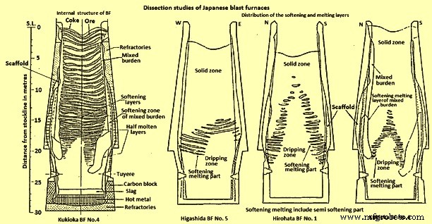
図1日本の高炉の解剖研究
削減レベル –広畑BF号の各負担層の削減の程度の研究。 1とKukiokaBFno.4は興味深い機能を引き出しています。 One of the interesting features is the fact that very little reduction occurs until the burden reaches the cohesive zone, wherein reduction proceeds rapidly. One of the major problems with water quenching is the possible reoxidation of the burden material during the cooling period and laboratory tests were conducted to determine the extent of reoxidation which might be taking place. One study was made to measure the reoxidation of sinter, in the laboratory, under the same cooling conditions existing during quenching of a BF, using a series of different initial reduction levels. The another study used another technique employing burden materials of various reduction degrees cooled from three different temperatures (400 deg C, 800 deg C and 1000 deg C) at a cooling rate of 200 deg C per hour in a nitrogen (N2) atmosphere. In this study it has been found that although the reduction temperatures and reduction degrees were different, the final reoxidation degree was around constant at 20 % to 25 %, i.e. the reoxidation increased in proportion to the initial reduction degree. At temperatures below 300 deg C, no reoxidation occurred. The result of these experiments is that the reduction levels were required to be increased, for example, from 10 % to 30 % to 15 % to 40 %. These corrected levels were in agreement with the reduction levels found in Russian dissection studies on a N2 quenched furnace.
Temperature profiles – The temperature isotherms within the furnaces were estimated by a combination of several methods. In one method, ‘Tempil’ pellets encased in numerous graphite holders were charged prior to blowing out the furnaces. This technique allowed the estimation of the temperature within the range 200 deg C to 1800 deg C, but one of the problems with this technique was that there was no method of controlling the distribution of the graphite holders within the BF. The other methods employed were measurement of the extent of coke graphitization, thus estimating the temperature between 1200 deg C and 1700 deg C. Measurement of the coke electrical resistance, which allowed temperature estimation between 1100 deg C and 1700 deg C and finally the degree of iron ore fusion was measured to estimate temperatures within the range of 900 deg C to 1400 deg C.
Comparing the isotherms with the distribution of the softening-melting burden layers (Fig 1 and Fig 2), it was found that the cohesive zone exists over a temperature range of around 1100 deg C to 1500 deg C for BFs operating mainly on sinter burdens.
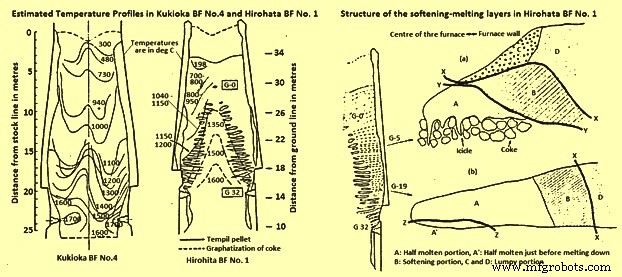
Fig 2 Estimated temperature profiles in Kukioka BF no. 4 and Hirohata BF no. 1 and structural of the softening-melting layers in Hirohata BF no. 1.
Burden layer structure within the cohesive zone – The type of structure of an individual burden layer in the cohesive zone depends upon the position of the layer within the BF. Two layers from Hirohato BF no.1 are shown in Fig 2. Layer G-5 is near the apex of the cohesive zone, while layer G-19 is situated near the base of the cohesive zone. Layer G-5 has four distinct zones, two of which are lumpy or granular portions (C and D). Layer G-19, on the other hand, contains only one lumpy portion, D. Apart from the obvious shape differences between the layers, the other main difference is the replacement of the icicles’ in layer G-5 by a half-molten portion just prior to melting down, A in layer G-19.
As seen earlier a substantial amount of reduction takes place in the cohesive zone and this has been proved by the reduction data obtained for each portion as given in Tab 1, and Tab 2. The figures are on the low side, as reoxidation, caused by the act of water quenching, certainly have taken place. The reason for the high reduction level of portion C is attributed to the slightly lower reduction temperature while in contact with the coke.
| Tab 1 Degree of reduction of the burden materials in the softening-melting layers of Hirohata BF no. 1 | ||||
| Softening-melting layer | Portion* | Reduction degree % | ||
| Sinter | Ore lump | Pellet | ||
| G-5 | A | 65.6 | 65 | 79.3 |
| C | 72.8 | 68.2 | 81.2 | |
| D | 11.5 | 12.3 | 14.6 | |
| G 19 | D | 35.4 | 36.6 | 41.3 |
| * B:Softening portion, C and D:Lumpy portion | ||||
| Tab 2 Degree of reduction of the pellets in the lumpy portion | ||
| Softening-melting layer | Sampling position (distance from the boundary*) (m) | Mean value of the reduction of the sample pellets (%) |
| G3 | 2 | 12.7 |
| 0.2-around 0.3 | 23.1 | |
| G10 | 1 | 14.1 |
| 0.2-around 0.3 | (55)** | |
| G12 | 1.3 | 13.9 |
| 0.9 | 14.3 | |
| 0.5 | 12.3 | |
| * Between the lumpy and softening portions | ||
| ** The value of the reduced pellet being not reoxidized | ||
The thickness of the softening-melting layers in Hirohata BF no. 1 ranged from 400 mm to 500 mm, in the case of the upper layers, to 70 mm – 100 mm for the layers near the base of the cohesive zone. The diminishing thickness is due to compaction, caused by the pressure exerted by the weight of material above the layer and also because of a natural thinning of material due to the increase in furnace diameter as the material descends. In the softening portions iron ore granules were combined in contact with each other. Sinter particles in the layers deformed very little, unlike pellets, which showed signs of deformation.
The process of pellet metallization can take place in one of three modes namely (i) the metallic iron is uniformly distributed within a pellet, (ii) a metallic shell is formed, leaving a wustite core, and (iii) wustite within the pellet reacts to form a slag and moves towards the metallic iron shell, leaving a central cavity. The reason for these three possible modes is not connected with the distribution within the softening-melting layer, but can be due to differences between the pellets or uneven gas flow in the softening-melting layer.
It has been found that the half molten portion consisted of highly compacted metallic iron and a small quantity of slag. Any limestone or olivine present remained unslagged. The icicles extend into the coke voids and consist of a metallic shell with a hollow interior, with small droplets of slag adhering to the iron. The higher the softening-melting layer within the furnace, the greater the length of the icicles, e.g. level G-1 produced some icicles of several hundreds of millimeters in length, while the lower layers produced icicles only 10 to 20 millimeters long.
The structure of the softening-melting layers in Kukioka BF no.4 was basically identical to those described for Hirohata BF no.1, except the thinner burden layers made the structure less distinct and the icicles smaller.
Slag composition changes – The major chemical change of the slag phase in the softening-melting layers is a decrease in the FeO content as the slag trickles down from the melting portion. Although large differences were detected by x-ray microanalyses of slags in portion A, ranging from 2 % to 20 % FeO, depending upon the location, the FeO content of the slag immediately prior to separation from the softening-melting layer was only 2 % to 3 %. The type of slag was not significantly different to that found in the normal sinter product, but in the ore granules a considerable quantity of fayalite was produced. Descent of the slag results in a gradual change in composition. The gradual increase in the CaO/SiO2 ratio is attributed to fluxing with limestone and a drop in the SiO2 content, caused by SiO2 reduction. The rise in Al2O3 is created by the incorporation of coke ash into the descending slag.
Metal composition changes – Considering the changes in metal composition as it descends the furnace; the carbon content of the metal in the half-molten portion of the softening-melting layer is around 0.2 % in the upper part and 0.35 % to 0.57 % in the lower part. The source of C in these half-molten layers is attributed to the carburizing action of the CO, except for the metal in contact with coke. Similar trends are visible in the layers found in Kukioka BF no.4. The rise in the C content of the icicles is attributed to the metal being in direct contact with particles of coke. Two distinct processes have been identified which are operating for the separation of metallic iron from the layers. The first mechanism is via the icicles which form at 1350 deg C to 1400 deg C and drip into the coke bed. Reduction of the iron oxides present in the icicles occurs rapidly to produce metallic iron. The second process occurs in layers in which no icicles form. In this situation, the metallic iron is carburized by the underlying coke until it reaches a C level such that melting can occur at the pertaining temperature. In this case the temperature of meltdown is around 1500 deg C.
The question of the mechanism of silicon pick-up by the metal within the furnace has been the subject of considerable discussion. Studies carried out in the experimental BF at Liege, Belgium fitted with sampling probes have found that the silicon level rise gradually from the melting zone to the hearth, such that 75 % of the final HM silicon is achieved by the time the metal reached the tuyere level. The Japanese dissection studies on the other hand reveal that the silicon level of the metal at the tuyere level is far in excess of that of the tapped HM. An explanation for this discrepancy between the two groups of studies can be that silicon pick-up had occurred during the process of water quenching the Japanese furnaces. During the experiments conducted to determine the probability of silicon pick-up during quenching, it was found that silicon pick-up from any slag present could be a possibility. Hence, this is to be borne in mind when analyzing the Japanese dissection data.
The sulphur (S) level of the metal within the softening-melting region is much higher than the concentration in the tapped HM. In the granular zones very little increase in S level occurs, which can be due to the materials in the softening-melting zone absorbing the S from the ascending gases, rather than a lack of absorption capacity by the burden in the granular zones. The lack of substantial quantities of S in the gas in the stack of the furnace can explain the horizontal profile at temperatures below 800 deg C. Further, as the temperature and slag basicity rise, the distribution of S between the slag and metal increases accordingly. Some idea of how S recirculates within the BF can be seen in Fig 3 in which the circulation of S within Hirohata BF no. 1 is shown.
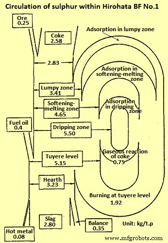
Fig 3 Circulation of sulphur within Hirohata BF no. 1
Size distribution – The change in physical size of the burden components during their descent was determined from the quenched furnace data and one of the major problems with this part of the study was that breakdown of material occurs during the quenching operation. Degradation of sinter reaches a maximum at temperatures of 400 deg C to 600 deg C and increases with the retention time. At levels of reduction in excess of 30 %, very little degradation occurs. Estimation of the cooling pattern of Kokura BF no.2 shows that the burden materials are exposed for a lengthy period of time to conditions which lead to considerable breakdown. The effect of the water quenching operation on the degradation of sinter was calculated. This calculation indicates that the sinter degradation increases with time after blow out and considerable degradation occurs in the region around the middle of the shaft.
Applying this to a centre working furnace (centre working means that the majority of the gas flows up the central axis of the furnace), it has been noticed that the degradation of sinter in the central zone of the furnace, where the reduction degree is high, is mainly caused by the reduction processes during operation. The situation in the peripheral zone is that the reduction degree is low and in this situation the breakdown is mainly caused by the long residence time of materials around 500 deg C during blowing out of the furnace. This was illustrated with the dissection results for the centre working Hirohata BF no.1. Another factor in maintaining the size of the burden materials is that in the central region of Hirohata BF no. 1, cracks if generated fused immediately because of the high temperatures and the rapid reduction taking place. Degradation is generally a problem having maximum concerns with sinters. Examination of the size distribution of pellets revealed that they were hardly pulverized and maintained their original shape.
Influence of gas flow – To further prove that the determination of the shape of the cohesive zone is by the gas flow within the furnace, core samples were taken from the Hirohata BF no.1 and Kukioka BF no.4 and their permeability was determined. Then their permeability was related to gas flow and gas velocity distribution profiles were prepared. These profiles can be directly related to the softening-melting layer distribution. The gas flow in the lower part of the BF is fast, 7 m/sec to 9 m/sec but slows considerably in the softening-melting layers to 2 m/sec to 4 m/sec thus indicating the poor permeability of the softening-melting layers. As the gas ascends the shaft its velocity naturally decreases due to the drop in gas temperature.
Cohesive zone control
It has been shown that the shape of the cohesive zone varies from BF to BF and much attention needs to be given for its control. The control of the cohesive zone is very dependent upon burden distribution. For maximum production, at the expense of fuel rate, a strong centre working profile is to be adopted, but if the fuel rate is to be minimized, then a less centre working practice is to be followed. Indeed, this is very much visible when comparing a strong centre working furnace, like Hirohata BF no.1 with moderate centre working furnace, like Kukioka BF no. 4. This point can be well explained by relating productivity to the height of the cohesive zone above the tuyeres (Fig 4). The higher the position of cohesive zone in the furnace, the greater is the productivity, although at the expense of an increase in fuel rate.
Another point concerning control of the cohesive zone is its effect on the refractory lining. If the wall temperature of the furnace is too high, then refractory wear is appreciable and one can expect a reduced life of the BF. Thus, for maintaining the refractory thickness, it is necessary to control the cohesive zone so that the wall temperatures are maintained at minimum levels.
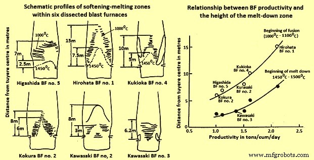
Fig 4 Schematic profiles of softening-melting zones and relationship BF productivity and height of the melt-down zone
Melting processes
The role of S in the melting process is governed by the Fe-S-O phase diagram. There is a necessity of a reaction between solid metallic iron and wustite in the burden with gaseous S, in the ascending gases. These phases react to form a eutectic of chemical composition 24 % S, 9 % O2, and 67 % Fe, having a melting point of 915 deg C. Once formed this liquid gains temperature as it descends the furnace, dissolving solid metallic iron and wustite which cause a change in liquid composition along a path until at certain point, the liquid splits into two conjugate liquid phases. Further increases in the temperature cause first part of the liquid to dissolve more solid iron, moving its composition along a path while the second part of the liquid dissolves more iron oxide and moves along the another composition path. Thus there are two phases (i) a liquid metal phase, and (ii) a liquid slag phase. The presence of silica in the system does not appreciably alter this mechanism. Indeed it moves the miscibility gap. Hence the separation of the nascent liquid into liquid metal and liquid slag phases occur at lower temperatures.
Once formed the two liquids go their own separate ways. The liquid metal dissolving solid iron, C and S become the final metal phase. The slag during its descent dissolves alumina, silica and lime from the coke ash, burden gangue and fluxes to form the final slag phase. A study has also shown that that the presence of hydrogen sulphide, in a CO / N2 gas mixture, lowered the melting point of iron ore sinters and pellets due to the formation of the liquid Fe-S-0 phase.
Alkalis are also thought to be closely associated with the initial melting process in the BF. Study with regards to the distribution of alkali, shows that the alkali is concentrated in the softening-melting layers. The reason for this is that alkali compounds, inherent within the burden and coke charged into the furnace are reduced and at temperatures in excess of 800 deg C to 900 deg C, the alkalis vapourize, as a metallic element or as a cyanide, and are swept into the softening-melting layers where they concentrate . As the softening-melting layers descend the alkali evaporates and continues the cycle.
製造プロセス