


パッシブアルカリ直接エタノール燃料電池におけるQPVAベースの膜のエタノール透過性とイオン伝導度に対する酸化グラフェンの影響
要約
パッシブアルカリ直接エタノール燃料電池(アルカリ-DEFC)は、携帯機器の持続可能なエネルギーを生産するのに適しているようです。ただし、エタノールのクロスオーバーは、パッシブアルカリ-DEFCシステムの主要な課題です。この研究では、エタノール透過性を低下させ、受動的アルカリ-DEFC性能の向上につながる、架橋四級化ポリ(ビニルアルコール)/酸化グラフェン(QPVA / GO)複合膜の性能を調査しました。複合膜の化学的および物理的構造、形態、エタノールの取り込みと透過性、イオン交換容量、水分の取り込み、およびイオン伝導度を特性評価および測定して、燃料電池への適用性を評価しました。膜の輸送特性はGO負荷の影響を受け、最適負荷は15 wt。%で、1 MのKOHをドープすると、エタノール透過性が最も低くなります(1.49×10 -7 cm 2 s -1 および3.65×10 −7 cm 2 s -1 それぞれ30°Cと60°Cで)および最高のイオン伝導度(1.74×10 -2 S cm -1 および6.24×10 −2 S cm -1 それぞれ30°Cと60°Cで)。パッシブアルカリ-DEFCでは、最大電力密度は9.1 mW cm -2 でした。 、市販のNafion 117 / KOH(7.68 mW cm -2 )よりも高い )2Mエタノール+2 MKOH溶液を使用して30°Cで。 60°Cの場合、達成された複合膜の最大出力密度は11.4 mW cm -2 でした。 。
はじめに
燃料電池は、燃料の化学エネルギーを燃焼せずに直接電気エネルギーに変換する電気化学デバイスです。この技術は、従来の方法と比較して、電気エネルギーを提供するのにより効率的です。燃料変換の60%を達成できますが、従来の方法では、電気エネルギーを生成するためにいくつかの変換ステップが必要です[1]。さまざまな種類の燃料電池の中で、直接エタノール燃料電池(DEFC)は、他の種類の燃料電池よりも燃料の保管が簡単で、設計が簡単で、毒性の少ない燃料を使用するため、有望な携帯型電源です[2,3、 4]。
ポータブル電源デバイスアプリケーションの場合、燃料供給の概念と取り扱いが容易なため、パッシブDEFCはアクティブDEFCよりも適切で信頼性が高いようです。パッシブフィーディングシステムは、レドックス反応のために酸素を供給するために燃料と空気の呼吸のためのポンプを必要とせずに、自然の毛細管力を採用しています。したがって、追加の消費電力は必要ありません。単一セルのコンパクトで軽量な構造は、外部ポンプとブロワーを必要とするアクティブセルとは異なり、セルを拡大するコンパクトなデバイス用に開発できます[5、6、7]。残念ながら、パッシブDEFCの2つの欠点は、商用利用を妨げています。アノードの動電学的反応が遅いことと、アノードからカソードへのエタノール透過性が高いことです[8]。現在、Nafion®はDEFCで使用されており、プロトン伝導性が高く、機械的安定性が高いため、酸性およびアルカリ性媒体のその他のタイプの燃料電池でも使用されています。ただし、Nafion®メンブレンには、エタノールバリアの不良、製造コストの高さ(米国エネルギー省の目標である〜40 $ / m 2 よりも高い)など、DEFCの商品化を妨げるいくつかの欠点があります。 )、およびその生産における有害物質の使用。 DEFCの高いエタノール透過性は、電力損失とカソード触媒汚染をもたらします[8,9,10]。
上記のパッシブDEFCの問題に対処するために、パッシブアルカリ直接エタノール燃料電池(アルカリ-DEFC)が代替システムとして研究者によって調査されました。パッシブアルカリ-DEFCはアルカリ条件で機能し、酸性条件システムに比べて次の利点を実現します。(1)アノード触媒でのエタノール酸化速度が速い、(2)Agなどの非白金触媒を使用するコストまたはNiは低く、(3)OH - 流れの方向は膜内のエタノール拡散流と反対であり、イオン運動の影響が少ないため、膜のエタノールクロスオーバーを大幅に減らすことができます[11、12、13]。 「DEFCの心臓部」として、陰イオン交換膜の使用が近年広く研究されています[8]。市販の第四級アンモニウムAEMは、水酸化物アニオンを伝導できます。残念ながら、AEMの導電率はまだ不十分です。さらに、従来のAEMの官能基は、高濃度のアルカリ燃料消費に必要であり、動作温度が60°Cを超えると劣化します[14、15、16、17]。したがって、パッシブアルカリ-DEFCアプリケーションには、AEM用の代替膜が緊急に必要です。
ポリ(ビニルアルコール)(PVA)は、その優れた化学的耐性、機械的安定性、および燃料バリアとして機能する能力により、市販のAEMに取って代わる可能性のある魅力的なポリマーです。さらに、PVA膜の調製は、膜形成プロセスが非常に簡単であり、そのヒドロキシル基の親水性が架橋反応のための高密度の反応部位を促進し、膜の機械的特性と熱安定性を向上させるため、簡単です[18、 19、20、21]。 PVAベースのメンブレンの最大出力密度は8.0mW cm -2 まで達する可能性があります アルカリDEFCおよび82mW cm -2 のパッシブモードの周囲条件下 以前の研究[4、13]で報告されているように、アルカリDEFCのアクティブモードでは80°Cで。
アルカリ性媒体では、PVAをドープした水酸化カリウム(KOH)により、PVAが効果的な安定した電解質になり、水素結合と双極子-双極子相互作用が形成され、AEMの安定した構造で良好なイオン伝導性が得られます[22、23、24、25 ]。以前の研究に基づくと、KOHをドープしたPVAベースの膜は、フェントン溶液(レドックス環境など)に耐え、優れた耐薬品性を示します[23、26]。したがって、この組み合わせは、他の陰イオン交換膜よりもアルカリ処理に対する化学的安定性が高くなります。ナノフィラーがPVAマトリックスに組み込まれている場合、物理的な架橋メカニズムにより、寸法安定性がさらに向上し、水とエタノールのクロスオーバーへの溶解に抵抗することができます。さらに、PVAは、DEFCの製造コストを削減する安価な材料であり、無毒で生分解性であるため、環境に優しい材料になります[11、23、27、28]。
残念ながら、AEMとして適用した場合のPVAには2つの大きな欠点があります。これには、イオン伝導率が低いことと、水分の取り込みが多いために膨潤率が高いことです[29、30]。 PVAマトリックスへの第4級アンモニウム官能基の導入は、イオン伝導性の向上に重要な役割を果たします。四級化ポリ(ビニルアルコール)(QPVA)は、PVAをグリシジルトリメチルアンモニウムクロリド(GTMAC)で修飾したものです。 QPVAは、イオン伝導度が低いという問題を解決するだけでなく、親水性と水の選択性を向上させます[31、32、33、34]。 Xiong etal。 [31]は、QPVA膜のイオン伝導度が7.34×10 -3 であると報告しました。 S cm -1 AEMとして、Yang etal。 [34]は、QPVAベースの膜のイオン伝導度を2.11×10 -2 まで高めることに成功しました。 S cm -1 60°Cで。しかし、私たちの知識に基づくと、パッシブアルカリ-DEFCシステムでのQPVAベースの膜の可能性を発見するための作業はまだ行われていません。
以前の研究で報告されているように、QPVAベースの膜は吸水率が高いため、燃料の透過性が高くなり、機械的強度が低下します。この状態は、無機フィラーまたは他のポリマーとのブレンドプロセスによって改善され、QPVA複合材料ベースの膜を形成することができます[35、36]。 Rajesh Kumar etal。 [37]は、QPVAベースの膜のエタノール透過性が高く、(0.95–2.08)×10 -6 の範囲であると報告しました。 cm 2 s -1 。この研究では、QPVAをAEMとして酸化グラフェン(GO)と組み合わせて、エタノール透過性が低くイオン伝導性が高いパッシブアルカリ-DEFCの性能を向上させます。現在、GOは、ポリマーの熱的および機械的強度を向上させる可能性、豊富な機能の存在による優れたネットワーク能力などの特殊な特性により、最も広く使用されている無機材料です。 GOは、GOの端に存在するヒドロキシル、カルボキシル、エポキシ基などの酸素官能基のため、高分子電解質のフィラーとして適しています。この親水性領域は、ポリマー電解質を横切って陰イオンを移動させるのに役立ちます[38、39、40、41]。 Karim etal。 [42]は、GOのイオン伝導度がほぼ10 -2 であると報告しました。 S cm -1 酸化グラファイトのバルクよりも高い(10 -4 S cm -1 )。さらに、芳香環の疎水性領域(sp 2 GOナノシート構造のカーボン層)は、燃料のクロスオーバーの問題を減らし、強力な共有結合による機械的強度を高めるのに役立ちます[40、41、42、43、44]。リンら。 [44]は、GOシートが10 -7 までNafion®115膜の燃料透過性を低下させることができたと報告しました。 cm 2 s -1 。 Ye etal。 [45]アルカリ直接メタノール燃料電池にPVA / GO電解質膜を適用して、セルの性能を向上させました。これにより、イオン伝導率が約126%増加し、燃料透過性が55%減少しました。
明らかに、パッシブアルカリ-DEFCシステムで架橋されたQPVA / GO複合膜の性能を調査する前に報告された研究はありません。この研究の目的は、エタノールのクロスオーバーを効果的に減少させ、パッシブアルカリ-DEFCの性能を向上させる適切なナノフィラー負荷を備えた自己合成QPVAベースの膜を準備することです。自家製のGOは、膜の性能を高めるために、溶液キャスティング法中にQPVAポリマーマトリックスに分散されました。異なるGO負荷を持ち、1 M KOHをドープした、調製した架橋QPVA / GO複合膜の特性を、液体の取り込み、イオン交換容量、イオン伝導度、エタノール透過性などのいくつかのテストによって評価しました。 GOの最適な組成は、膜選択性測定に関する最高の性能に基づいて決定されました。受動アルカリ-DEFCでアルカリ電解質膜を提供するための、架橋QPVA / GO複合膜と水酸化カリウム(KOH)をドープした市販のNafion 117膜(Nafion 117 / KOHとして設計)の性能比較を検討しました。パッシブアルカリ-DEFCでの代替AEMの適用に関するガイドライン。
方法論
資料
ポリ(ビニルアルコール)(PVA)(Mw 85,000〜124,000、99 +%加水分解)、グラファイト粉末、硝酸ナトリウム(NaNO 3 )、過マンガン酸カリウム(KMnO 4 )、およびグリシジルトリメチルアンモニウムクロリド(GTMAC)は、SigmaAldrichから提供されました。グルタルアルデヒド(GA、蒸留水中25%)は、日本のナカライテスクから提供されました。リン酸(H 3 PO 4 )、硫酸(H 2 SO 4 )、塩酸(HCl)、水酸化ナトリウム(NaOH)、および水酸化カリウム(KOH)はJ.T.から購入しました。ベイカー、および過酸化水素(H 2 O 2 )はHmbGChemicalから購入しました。これらの市販の材料はすべて、精製せずに使用されました。
四級化されたPVAの合成
マグネチックスターラーで90°Cで2時間撹拌しながら、適切な量のPVAを脱イオン水に溶解しました。得られたPVA溶液が均質で透明、粘性になったとき、溶液の温度を65°Cに下げました。次に、適切な量のGTMACとKOH(GTMAC:KOH =1:1 mol比)を導入し、得られた均質で無色の溶液を4時間連続して攪拌しました。無水エタノールを溶液に加えて、四級化ポリ(ビニルアルコール)(QPVA)の黄色の沈殿物を得た後、沈殿物を真空オーブンで乾燥させた。
酸化グラフェンの合成
Hummerの方法は、酸化グラフェン(GO)の合成に使用されました[46]。 2グラムのグラファイトを2gのNaNO 3 と混合しました メスフラスコ(500 mL)に入れます。次に、150mLのH 2 SO 4 を混合物に加え、混合物を氷浴(0〜5℃)で30分間連続的に撹拌した。次に、12gのKMnO 4 を混合物に加え、反応温度を20℃未満に4時間維持した。氷浴を取り除き、溶液がペースト状で茶色に見えるまで、反応物を35℃で1日間撹拌した。次に、溶液を100 mLの脱イオン(DI)水で希釈して、茶色の溶液を形成しました。次に、200mLの水を加えて温度を下げました。最後に、10mLのH 2 O 2 溶液を処理するために注がれ、黄色が観察された。遠心分離機を使用して溶液を10%HClで精製し、精製ステップのためにDI水ですすぎを数回行いました。
架橋QPVA / GO複合膜の調製
架橋QPVA / GO複合高分子膜の調製ステップの概略図を図1に示します。QPVA(8 wt。%)を75°Cで1時間マグネチックスターラーで攪拌することにより、DI水に完全に溶解し、均質なものを形成しました。透明なソリューション。さまざまなGO含有量(5 wt。%〜20 wt。%)の溶液は、GO溶液(1 g / L)を希釈することによって提供されました。 QPVAの溶液を、GO溶液(2:1の体積比)を1時間加えながら連続的に攪拌して、黄褐色のQPVA / GO溶液を生成しました。黄褐色の溶液を10wt。%GAで30分間継続的に攪拌しました。溶液をプラスチックプレートにキャストし、溶液の量を制御して膜の厚さ(0.015 mm)を固定しました。次に、周囲条件下で24時間、60°Cの真空オーブンで12時間乾燥させます。メンブレンをプラスチックプレートから剥がし、ガラスプレート上に置いて100°Cで1時間のアニーリングプロセスを行いました。次に、メンブレンを1 M KOH溶液に80°Cで24時間浸しました。膜の表面の余分なKOHは、DI水で繰り返しすすぐことによって除去され、膜は使用前に室温でDI水に保存されました。
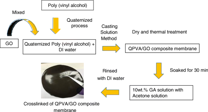
QPVA / GO複合膜の調製の概略図
複合膜の構造的および形態学的特性評価
フーリエ変換赤外分光分析
手付かずのPVA膜、手付かずのQPVA膜、および架橋QPVA / GO 15 wt。%複合膜の赤外吸収スペクトルを、ATR(減衰全反射)モジュールを備えたPerkin Elmerフーリエ変換赤外分光法(FTIR)で記録しました。サンプルはサンプルホルダーに保持され、ATR-FTIRシステムに配置されました。 FTIR研究は周囲温度で実施され、スペクトル範囲は400〜4000 cm -1 でした。 。
X線回折
X線回折(XRD、モデルD8 Advance、Bruker AXS Germany)の測定値は、架橋QPVA / GO複合膜から得られ、結晶化度を調べました。 X線放射は、40kVおよび40mAの動作電力のアノードからのCuKα放射(波長0.15406 nm)を使用して生成されました。スキャン速度は0.5°s -1 、および解像度は0.02°でした。 XRDスペクトルは10°から50°の角度で記録されました。
フィールドエミッション走査型電子顕微鏡–エネルギー分散型X線分光法、透過型電子顕微鏡法、および原子間力顕微鏡法
>架橋QPVA / GO複合高分子膜の表面および断面の形態を、ZEISS SUPRA 55 VP電界放出型走査電子顕微鏡(FESEM)を使用して10kVで観察しました。エネルギー分散型X線分光法(EDX)を元素マッピングに使用しました。液体窒素で冷却した後、乾燥膜を手動で破砕した。透過型電子顕微鏡法(TEM-Hitachi HT 7700、日本)と原子間力顕微鏡法(AFM)を実施して、剥離したGOの存在とサイズを示しました。
熱重量分析
複合膜の熱特性は、熱重量分析(TGA)によって決定されました。 PVAメンブレン、QPVAメンブレン、およびQPVA / GO複合メンブレンのサンプルを、窒素雰囲気下で周囲温度から600°Cまで10°C分刻みで加熱しました -1 熱重量分析装置(TGA Q500 V20.13ビルド39)を使用します。
膜の取り込み、膨潤率、イオン交換容量、および酸化安定性
膜のアルカリ、水、およびエタノールの取り込みは、水和前後の架橋QPVA / GO複合膜の損失重量から決定されました。アルカリ取り込み手順は、メンブレンサンプルを30°Cで24時間2 MKOHに浸すことによって実行されました。次に、サンプルをKOHから取り出し、ティッシュペーパーでサンプルから表面湿度を取り除き、サンプルをすぐにマイクロバランスマスで秤量して、湿った膜の重量( W )を求めました。 ウェット )。次に、サンプルを100°Cの炉で2時間乾燥させて、乾燥した膜の重量( W )を決定しました。 ドライ )。アルカリ吸収( W )は、次の式を使用して計算されました。 (1):
$$ W =\ frac {W \ \ mathrm {wet} -W \ \ mathrm {dry}} {W \ \ mathrm {dry}} \ times 100 $$(1)水とエタノールの取り込みについては、溶液処理を水と2Mエタノールに置き換えることで手順を変更しました。
架橋QPVA / GO複合高分子膜の膨潤率は、100 mm 2 を浸漬することによって調べられました。 25°CのDI水中で24時間サンプルを採取します。次に、脱イオン水からサンプルを取り出し、ティッシュペーパーで表面湿度を取り除き、膜の厚さを測定して、濡れた膜の厚さ( t )を求めた。 ウェット )マイクロメータ(ミツトヨ、±1μm)を使用します。次に、サンプルを100°Cの炉で2時間乾燥させて、乾燥した厚さ( t )を決定しました。 ドライ )。膨潤率(Sr DI水 )は、次の式を使用して計算されました。 (2):
$$ Sr =\ frac {t \ \ mathrm {wet} -t \ \ mathrm {dry}} {t \ \ mathrm {dry}} \ times 100 $$(2)古典的な滴定法を使用して、複合膜のイオン交換容量(IEC)を測定しました。複合膜を0.1M NaOH溶液に浸して、OH - に変換しました。 。次に、複合膜を脱イオン水で洗浄して過剰なNaOHを除去し、100mLの0.1MHCl溶液で48時間平衡化しました。次に、逆滴定を使用して測定された酸の還元からIEC値を決定しました。 IEC値の計算に使用される式(meq g -1 )を以下に示します:
$$ \ mathrm {IEC} \ kern0.37em \ left(\ mathrm {meq}。{\ mathrm {g}} ^ {\ hbox {-} 1} \ right)\ kern0.5em =\ kern0.75em \ frac {M _ {\ mathrm {b}}-{M} _ {\ mathrm {a}}} {m \} $$(3)ここで M b 平衡の前に必要なHClのミリ当量(meq)を表します M a 平衡後に必要なHClを表し、 m は、乾燥した複合膜の質量(g)です。
酸化安定性試験はフェントン試薬(3%H 2 )を介して測定されました。 O 2 2 ppm FeSO 4 を含む水溶液 )。サンプル(40mm×40mm)を25°Cでフェントン試薬に浸しました。浸漬前後の膜の重量を24時間後に記録しました。サンプルが溶液中で壊れたり溶け始めたりする際の膜の変化は、テストの最大時間の通知でした。
イオン伝導度、エタノール透過性、および選択係数
イオン伝導率は、インピーダンスアナライザーポテンシオスタット/ガルバノスタット(WonATech-WMPG1000)に接続された4電極伝導率セルを使用して決定されました。これは、E–I曲線の勾配から膜複合材料の抵抗を取得するために使用されました[47]。すべての測定は、式(1)を使用して実行されました。 (4):
$$ \ sigma =\ frac {L} {RS} $$(4)ここで、σ、 L 、 R 、および S プロトン伝導度を表します(σ、S cm -1 )、対極間の距離(L、cm)、膜の抵抗(R、S -1 )、および膜サンプルの断面積(S、cm 2 )、 それぞれ。架橋されたPVA / GO複合膜は、さまざまな温度(30〜60°C)の脱イオン水中で平衡化されました。膜は横方向に配置され、電極の間に挟まれました。
膜エタノール透過性を決定するために、2つのガラスコンパートメントを含む拡散セルが構築されました。 2つのコンパートメントグラスを分割して、2 M、4 M、6 M、または8 Mのエタノールで満たされたフィードコンパートメントと、脱イオン水で満たされた2番目のチャンバーを形成しました。各コンパートメントには、溶液を攪拌するためのマグネチックスターラーバーが含まれていました。メンブレンは2つのガラスコンパートメントの間に垂直に固定されました[47]。実験中、膜を通過したエタノールの濃度を測定した。膜透過性は、以下の式を使用して計算された。 (5):
$$ P =\ frac {1} {Ca} \ left(\ frac {\ Delta Cb(t)} {\ Delta t} \ right)\ left(\ frac {LVb} {A} \ right)$$( 5)ここで P 膜のエタノール拡散透過性を表します(cm 2 s -1 )、CaはセルAの供給チャンバーの濃度を表します(mol L -1 )、 ∆Cb ( t )/ ∆t 時間の関数としてのセルBのエタノール濃度のモル変動の傾きを表します(mol L -1 s)、Vbは各拡散リザーバーの体積を表します(cm 3 )、 A 膜を表し、 L 膜の厚さ(cm)を表します。すべての濃度溶液は屈折計で測定されました。架橋QPVA / GO複合高分子膜の選択係数(イオン伝導度とエタノール透過率の比)は、次の式を使用して決定されました。 (6)および(7):
選択性、
$$ \ Phi =\ frac {P} {\ sigma} $$(6)パッシブアルカリの単一セル–DEFCパフォーマンスおよび耐久性テスト
図2は、自家製のパッシブアルカリ-DEFCと膜電極接合体(MEA)の単一セルを示しています。パッシブアルカリ-DEFCテストセル用のMEAを構築し、ホットプレス機を介して複合膜を両方の電極(アノードとカソード)の間に挟みました。アノードには、Pt–Ru触媒を4 mg cm -2 で適用しました。 、カソードには、Pt触媒を4 mg cm -2 で適用しました。 手動鋳造技術を介してカーボン紙ガス拡散層に。 Pt–RuとPtは、米国のAlfaAesarから提供されました。 DEFCのパフォーマンスは、4 cm 2 のアクティブMEA領域を備えた自家製のシングルセルスタックを使用したパッシブエアブレスによってテストされました。 。シングルセルスタックの燃料リザーバー領域では、2mLの燃料を使用できます。分極データは、ポテンシオスタット/ガルバノスタット(WonATech)を使用して取得し、周囲条件下で単一セルに負荷電流を印加することによって電圧応答を測定しました。次に、2 M KOH + 2 Mエタノールが陽極リザーバー内で燃料として反応し、性能テスト中に周囲の空気がカソード開口部に拡散しました。パッシブアルカリ-DEFCの単一セルを調べて、60°Cで1000時間の耐久性テストを行いました。受動的な給油のため、エタノール溶液は12時間ごとに給油する必要があります。耐久性性能試験は、セル電圧を0.3Vで一定にした連続運転定負荷で実施しました。耐久性試験終了後、単セルの分極試験を繰り返し、性能を比較しました。
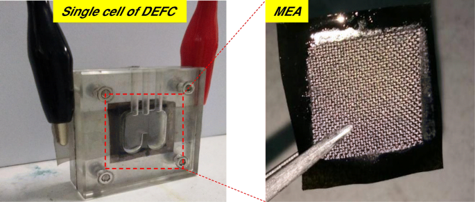
パッシブアルカリの単一セル–DEFCおよびMEA
結果と考察
複合膜の特性評価と形態
四級化の程度は2.6%で、残りの97.4%はPVAのマトリックスポリマーです[23]。 6つの異なるタイプの膜が製造されました。手付かずのPVA膜、架橋QPVA膜、および重量パーセントがそれぞれ5 wt。%、10 wt。%、15 wt。%、20 wt。%の4つの架橋QPVA / GO複合膜。表1に、EDX分光法による元のPVA膜と架橋QPVA / GO 15 wt。%複合膜の元素マッピングの結果を示します。 PVA複合膜には、炭素(C)と酸素(O)が含まれていました。一方、架橋QPVA / GO 15 wt。%複合膜には、炭素(C)、窒素(N)、および酸素(O)が含まれており、第4級アンモニウム基がPVAマトリックスにうまくグラフト化されたことを示しています。 GOをQPVAに導入すると、GOの酸素官能基(ヒドロキシル、カルボキシル、エポキシ基)により、複合膜内のOの重量と原子百分率が増加しました。 QPVAとGOの関与を裏付ける証拠は、FTIR分析からの振動分光法を使用してさらに調べられました。 PVA、QPVA、およびQPVA / GO 15 wt。%複合膜の官能基は、400〜4000 cm -1 の領域で記録されました。 、図3に示すように。
<図>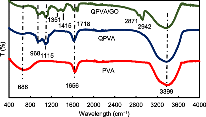
波長400〜4000 cm -1 のFTIRスペクトル
図3は、400〜4000 cm -1 の波長範囲を示しています。 。 686 cm -1 の吸収ピーク PVAメンブレンの脂肪族C–H曲げに対応します[3]。四級化と架橋プロセスの後、脂肪族C–Hの曲がりが減少し、架橋QPVA膜と架橋QPVA / GO 15 wt。%複合膜のスペクトルにいくつかの新しいピークが現れました。 968 cm -1 のピーク 脂肪族C-Nとして特徴付けられ、第4級アンモニウム基がマトリックスポリマーの主鎖にグラフトされたことを示しています[31]。そして、1115 cm -1 のピーク 架橋処理後に出現したC–O–C伸縮基を示し、架橋反応が発生し、複合膜がGAによって正常に架橋されたことを証明します[12]。未処理のPVAおよび架橋QPVAと比較して、複合膜に現れるいくつかの新しいピークがあります。 1351 cm -1 のピーク GOからのエポキシC-O対称振動を表します[23]。 1415 cm -1 のピーク GOからのカルボン酸基(O =C-O)の伸縮振動を表します[44]。 1656 cm -1 のピークの変形 sp 2 に対応する芳香族構造から伸びるC =Cの統合に起因する GO疎水性領域の特性とマトリックスポリマーの骨格の反応[39]; 1718 cm -1 の新しいピーク GOのカルボキシル基の-COOH伸縮に起因する[23]。新しいピークは、複合膜の2871 cm -1 に現れます。 、=C–Hストレッチに属し、2942 cm -1 、–CH 2 の非対称および対称ストレッチの増加 GOから観察することができます。 PVAの変更後、3399 cm -1 での強力で幅広い吸収 GOの官能基との水素結合の形成によって影響を受ける–OH伸縮の弱化が原因で観察できます。 FTIRスペクトル分析から、PVAの四級化プロセスとGOの合成のピークは、以前の研究[23、31、44]と同様の官能基と疎水性領域を明確に示し、架橋QPVA / GO複合膜が正常に機能したことを示しています。合成されました。
複合膜の結晶化度を観察するためにX線回折測定を行った。 XRD分析ピークの回折パターンの図を図4a、bに示します。 Lee etal。 [43]は、グラファイトのピークが25.6°にあることを報告しています。図4aは、グラファイトからGOへの相変化が進行する自家製GOのXRDスペクトルを示しています。酸化プロセス後にGOが剥離したため、ピーク強度は10.92°でわずかに高くなっています。この変化は、疎水性領域とGOベンゼン構造の端にある分散した酸素官能基との相互作用によって発生します[43]。図4aに示すように、19〜20°のXRDパターンの大きなピークの存在と39〜40°の小さなピークは、PVAの半結晶構造の指標でした。 19〜20°でのQPVAのピーク強度は、PVAの半結晶構造を乱すアンモニウム官能基の導入により、純粋なPVAと比較して減少しました。したがって、アモルファス領域はQPVAポリマーマトリックスのドメインになります。この構造は、ポリマー鎖の自由体積の増加によるイオン伝導性の向上に寄与し、ポリマーの局所的な構造緩和とセグメント運動を伴う膜を通るイオン経路として機能するより多くの自由空間を提供します[26]。図4bは、GOの大きな回折ピークが見えないことを示しています。これは、GOが物理的相互作用によってQPVAマトリックスに均一に分散していることを示しています。特に、2θ=10.92°のGOピークは、QPVAポリマーへの組み込みによる元のシートの完全な剥離と破壊のため、ほとんど見えませんでした。この結果は、架橋QPVA / GO複合膜の合成が、水素結合の形成と、ポリマー鎖とGOの官能基との間のイオンレベルでの相互作用を伴うことを確認しました[23、39]。 The diffraction intensity of the QPVA at 19–20° was still detected, implying that the degree of QPVA crystallinity was maintained until the additional of graphene oxide at 20 wt.% loading. Hence, the chemical structure of the QPVA composite films barely changed as the graphene oxide loading increased, indicating that there were many physical interactions but few chemical reactions occurring between the QPVA and graphene oxide in the composite membrane formation process [39, 48]. In addition, the amorphous structure of composite membrane has significant effect in ionic conductivity due to the formation of free volume by constantly fragmental movement of the polymer matrix. Thus, the presence of GA as a crosslinked and KOH as a doped inside the polymer matrix provided more pathway for ionic to pass through the membrane [27, 49,50,51].

a のXRDパターン GO, PVA, and QPVA; b QPVA, QPVA/GO composite membrane
The FESEM, TEM, and AFM images were used to identify the morphological features of GO as shown in Fig. 5. Figure 5a, b shows the FESEM and TEM images which clearly seems that the single layer of graphene oxide (likes a paper sheet) was successfully exfoliated from the graphite flakes. AFM was used to measure GO layer thickness of 0.87 nm as presented in Fig. 5c. The GO thickness obtained has confirm the exfoliated single layer of GO has successfully synthesized. The morphologies of the prepared membrane are shown in Fig. 6a–d by FESEM at a magnification of × 10.00 k. All the top view of FESEM images show that all membranes are dense and remain uncrack, although there are annealing in 100 °C, which proves the excellent chemical stability due to the cross-linkage and modification with GO in QPVA matrix. This characteristic is important for using as polymer electrolyte membrane in DEFC applications, especially to prevent the fuel crossover. The surface of the PVA membrane seems very smooth as shown in Fig. 6a, while the QPVA membrane in Fig. 6b shows a different morphology, as the grain distribution obviously appeared, indicating that the PVA was successfully grafted with quaternary ammonium groups [27]. Figure 6c shows the top view of the QPVA/GO composite membrane, indicating the random distribution of GO inside the QPVA which proved that GO has successfully exfoliated and dispersed throughout the membrane. From the cross-sectional view in Fig. 6d, the composite membrane exhibit a dense and compact structure with high homogeneity, indicating the unification of QPVA and GO in the composite membrane without any holes. In addition, the presence of GA and KOH filled the free volume inside the polymer matrix. This is the important characteristics for separation and fuel crossover reduction. Hence, the homogeneous exfoliation of GO, dispersion of GA and KOH improve the ionic conductivity and reduce the ethanol permeability [23, 24, 52, 53].

FESEM, TEM, and AFM image of exfoliated graphene oxide

a のFESEM画像 surface PVA membrane, b surface QPVA membrane, c surface of QPVA/GO composite membrane, and d cross section of QPVA/GO composite membrane
Thermal Stability
The thermal stability of the crosslinked QPVA/GO composite membrane was illustrated by TGA studies. Figure 7 shows the TGA curves for the pure PVA membrane, QPVA membrane, and QPVA/GO 15 wt.% composite membrane. The TGA curves of these three membranes present three major weight loss regions. The first region is at 70–130 °C due to the loss of adsorbed water in the membrane through the evaporation of the weak and strong physical and chemical bonds of water, respectively. The weight loss of all membranes is approximately 5–8 wt.%. The second transition region of weight loss at approximately 230–320 °C is ascribed to the decomposition of the side chains of the matrix polymers. The weight loss of the membrane was 75 wt.% for PVA, 70 wt.% for QPVA, and 60 wt.% for QPVA/GO; the total weight loss of PVA was the highest due to the presence of fewer side chain groups compared to QPVA/GO. The third transition region of weight loss at approximately 430–480 °C was ascribed to the decomposition of the main chain of the membrane due to cleavage of the C–C backbone of the matrix polymers. At 600 °C, the residual mass of the PVA membrane was 4.7 wt.%. The residual mass of the QPVA membrane and the QPVA/GO membrane were 7.67 wt.% and 22.2 wt.%, respectively.

TGA analysis of PVA membrane, QPVA membrane and QPVA/GO composite membrane
Figure 7 shows that the weight loss of the QPVA/GO 15 wt.% membrane was less than the other membranes; this result indicates that the quaternization process of the PVA matrix and the incorporation of GO inside the composite membranes was successful. The inorganic filler enhanced the thermal stability of the composite membrane and produced a strong network between the matrix polymer and the GO filler reinforcement. In addition, the chemical crosslink reaction by glutaraldehyde assists in the enhancement of thermal stability.
Alkaline Uptake, Swelling Ratio, and Oxidative Stability
Alkaline uptake is the major process for electrolyte preparation. The KOH used for alkaline doping serves as a charge carrier and cross-linker. The alkaline–DEFC was operated with alkaline anode fuel (alcohol in KOH solution). Alkaline uptake in the membrane is important for providing OH − イオン。 The optimal KOH uptake condition is necessary to provide high ionic conductivity. Nevertheless, excessive KOH uptake leads to the deformation of the matrix polymer and degrades the mechanical stability of alkaline–DEFC by shortening its lifetime. The dry membrane films were immersed in 2 M KOH at 30 °C, and the dimensional stability was estimated using the changes of the membrane weight for alkaline uptake and the width, length, and thickness for the swelling ratio of the membrane films before and after doping with 2 M KOH. Table 2 shows that the alkaline uptake of the PVA membrane was 105%. After the quaternization process, the hydrophilic structure C–H and the presence of quaternary ammonium groups led to an alkaline uptake of QPVA membrane increase up to 136%. However, the introduction of GO in QPVA associated the reduction of alkaline uptake until to 45% with 20 wt.% loading of GO. The hydrophobic region of GO contributes a “blocking effect” in the polymer matrix and thus reduced the KOH absorption of the membranes. Furthermore, the crosslinking agent might also reduce the alkaline uptake due to the more compact network structures formed in the composite membranes [23, 50]. The alkaline uptake has influence the swelling behavior of the composite membranes.
<図>The in-plane swelling (i.e., width and length) and through-plane swelling (i.e., thickness) ratios of the composite membranes are shown in Table 2. Generally, a low membrane swelling ratio is favorable for tolerating the dimensional match between the electrode and membrane; thus, the stable formation of MEA is encouraged during single cell performance. The in-plane and through-plane swelling ratios for the QPVA membrane were 18% and 60%, respectively. The introduction of GO up to 20 wt.% loading into QPVA reduced the in-plane and through-plane swelling ratios to 7.54% and 32%, respectively. The introduction of GO not only favors the formation of connected ionic transport channels but also expands the hydrophobic region of GO inside the matrix QPVA, which results in the dimensional stability of the composite membranes [23, 52]. The crosslinked QPVA/GO 20 wt.% composite membrane showed lower swelling ratios than the pristine QPVA membrane. Liao et al. [26] reported a low in-plane swelling ratio due to the strong interactions between the polymer matrix and filler, which involve dipole-dipole interactions, hydrogen bonding, and van der Waals interactions between the polymer and GO. All the samples exhibit good in-plane swelling ratios rather than through-plane swelling ratios, which are beneficial for the MEA contact conditions.
The oxidative stability of the anion exchange membrane was measured in the Fenton’s reagent test which is known as hastened oxidative stability test. Table 1 shows the retained weight percentage of the crosslinked QPVA/GO membranes. After 24-h immersion, the retained weight of the QPVA membrane is 97%. It was slightly declined with increasing of GO loading which retained weight of 91% for 20 wt.% of GO. The obtained results demonstrated that the free radicals have little impact on the QPVA-based membranes due to the greater oxidative resistivity of hydrogen bond formed between GO, GA, and polymer matrix. This may be due to the presence of oxygen contained functional groups present in the GO that easily forms hydrogen bonding with pristine QPVA [1, 23, 54]. The weight loss percentage results indicate that the crosslinked QPVA/GO membrane has good oxidative stability against Fenton’s reagent.
Water Uptake, Ion Exchange Capacity, and Ionic Conductivity
Water uptake is an important parameter for ionic transfer inside the electrolyte membrane. But, higher of water uptake will degrade the membrane performance [8, 50]. From the Fig. 8, the modification of QPVA-based membrane and GO has successfully reduce the water uptake form 145 to 46%. Ion exchange capacity (IEC) is an important parameter for evaluating the mobility ability of anion through the membrane. Besides, IEC is useful to determine the range of optimal water uptake which enhance the conductivity of membrane through the vehicle mechanism [33, 55]. Figure 8 shows that the values of the experimental IEC ranged from 1.05 to 2.71 meq g −1 according to the increase of GO loading. The existence of quaternary ammonium group grafts on matrix polymer and increasing amounts of GO has led to the addition of oxygenic functional groups, including hydroxyl, carboxyl, and epoxy groups, which are useful for anion transfer through the Hopping @ Grotthus mechanisms [22, 35]. Higher IEC values are the main indicator of higher ionic conductivity due to the high charge density inside the membrane [33, 55].

Water uptake and IEC analysis of QPVA membrane and QPVA/GO composite membrane at 30 °C
Figure 9 also shows the ionic conductivities of the QPVA membrane and the crosslinked QPVA/GO composite membrane at 30 °C. The ionic conductivity of the QPVA membrane (4.7 × 10 −3 S cm -1 ) is higher compared to the PVA membrane (1.05 × 10 −3 S cm -1 )。 The grafted quaternary ammonium group at the PVA backbone assists in increasing the ionic conductivity due to the OH − that has been transferred effectively through the pathway created by the presence of functional groups in GO [31]. The ionic conductivity of composite membranes was increased which recorded as 7.3 × 10 −3 S cm -1 , 11.3 × 10 −3 S cm -1 , and 17.56 × 10 −3 S cm -1 for GO loading at 5 wt.%, 10 wt.%, and 15 wt.%, respectively. The introduction of GO in the composite membrane up to 10 wt.% showed a slight increase in ionic conductivity attributed to the “blocking effect” of the GO sp 2 characteristic reacting as a hydrophobic region for ionic clusters in the composite membrane.

Ionic conductivity analysis of QPVA membrane and QPVA/GO composite membrane at 30 °C
However, beyond 10 wt.% of GO loading (15 wt.%), the ionic conductivity of the composite membrane increased to 17.35 × 10 −3 S cm -1 due to the sufficiently highly oxygenated functional groups (hydroxyl, carboxyl, and epoxy) in GO to provide alternative anion pathways as well as overwhelming the blocking effect from the hydrophobic region. Thus, the addition of GO has enhance the ionic conductivity of the composite membranes [43]. The oxygenic functional groups of GO, such as carboxyl groups, can form complexes with KOH molecules and form good ionic conductors with high-speed channels for anion exchange and transport. This condition is useful for hopping mechanism [23, 52]. Moreover, the strong interactions between GO, the polymer matrix, and GA form a three-dimensional network that can hold water and alkaline molecules that are important in the Vehicle mechanism. Ionic transport depends on the alkaline molecules and water uptake occurs by the vehicle mechanism. In the composite membranes, the alkaline molecules could be classified as free alkaline and bound alkaline. For conductivity, only the free alkaline affects the anion transport [23, 56]. Figure 10a presents the ionic transport illustration for crosslinked QPVA/GO composite membrane.

a Illustration of ionic transfer for the crosslinked QPVA/GO composite membrane. b Illustration of ethanol transfer for the crosslinked QPVA/GO composite membrane
However, when the GO loading exceeded 20 wt.%, the ionic conductivity of the composite membrane declined due to the decrease in alkaline uptake by the composite membrane, which was attributed to the GO hydrophobic region. Hence, this condition disturbs the Grotthuss mechanism in conveying the ionic diffusion, thus reducing the ionic conductivity of the composite membrane. Higher temperature increases the ionic conductivity due to the effect of fast anion mobility. In addition, the distance between the polymer chains becomes larger at higher temperature, providing more free volume and facilitating water molecule movement to enhance anion conductivity [1, 45]. Figure 11 shows the trend of the ionic conductivity when the temperature increased. Increasing temperature also led to increasing ionic conductivity. The highest ionic conductivity was 4.6 × 10 −2 S cm -1 at 60 °C for 15 wt.% GO loading. Compared to the previous study on PVA-based membranes in DEFCs, such as PVA/HPW/DPTA, PVA/TMAPS, PVA/LDH, and PVA/CNTs [11,12,13, 50], the current QPVA/GO membrane showed the highest ionic conductivities.

Ionic conductivity analysis of QPVA membrane and QPVA/GO composite membrane at different temperature
The ln σ and 1000/T plots are shown in Fig. 12 with the assumption that the ionic conductivity follows Arrhenius behavior. The activation energy E a of the transferred ion in the composite membranes can be obtained according to the Arrhenius equation:
$$ {E}_a=-b\times R $$ (7)
Ln σ vs. 1000/T plot for the QPVA/GO composite membrane; the lines indicate the linear regression
ここで b is the slope of the regression line for the plotted graph (ln σ vs.1000/T) and R represents the gas constant (8.314472 J K −1 mol −1 )。 The QPVA/GO 15 wt.% composite membrane has the lowest activation energy of 18.11 kJ mol −1 compared to the other composite membranes. The GO loading at 15 wt.% resulted in sufficient presence of functional groups in the composite membrane, also providing an optimal structure for the effective anion transport to subsequently contribute to the reduction of the activation energy.
Ethanol Uptake and Ethanol Permeability
Figure 13 shows the ethanol uptake and ethanol permeability of the pristine QPVA and the crosslinked QPVA/GO (5–20 wt.%) composite membrane in 2 M ethanol at 30 °C. One PVA property is its slight solubility in ethanol, which effectively reduces ethanol crossover [57]. The ethanol uptake clearly indicates that the QPVA polymer absorbs less ethanol than water. With 20 wt.% GO loading, ethanol uptake decreased by ~ 35% (from 52% by the pristine QPVA membrane to 34% by the crosslinked QPVA/GO 20 wt.% composite membrane). This behavior can be explained by the possible appearance of a three-dimensional network built by the crosslinking effect of GA on GO and the polymer matrix. These results are important because they can indicate the dimensional stability of the composite membranes under the set conditions and show their barrier properties and ethanol permeability. The reduction in ethanol uptake was mainly provided from the optimum GO loading, which increased the formation of a three-dimensional network between GA, GO, and PVA. Thus, the free volume of the polymer composite decreased and thus resisted the ethanol mobility pathway [12, 50, 55]. Figure 13 shows similar result of ethanol permeability for the pristine membrane and composite membranes. The ethanol permeability of the membrane decreased by ~ 85% (from 8.7 × 10 −7 cm 2 s -1 for the pristine membrane to 1.32 × 10 −7 cm 2 s -1 for the crosslinked QPVA/GO 20 wt.% composite membrane). The reduction of ethanol permeability is affected by increasing the GO content of the composite membrane. The three-dimensional network between GA, GO, and PVA formed a compact structure that increased the resistance of the membrane to ethanol crossover. Besides, the presence of KOH as electrolyte was fulfilled the free volume space in polymer matrix [24, 50, 55]. Figure 10b has illustrated the ethanol transport in crosslinked QPVA/GO composite membrane. The ethanol permeability of the composite membranes has also been studied in different ethanol concentrations (2, 4, 6, and 8 M) at 30 °C, as shown in Fig. 14. The result showed that the ethanol permeability is lower in order of range ~ 10 − 7 cm 2 s -1 。 The reduction in ethanol permeability was attributed to the presence of the hydrophobic region when the GO content increased, which functions as an ethanol crossover blockage [55, 58]. At the same temperature, the crosslinked QPVA/GO composite membrane exhibited lower ethanol permeability than the PVA/phosphotungstic acid solutions, with different percentages of diethylenetriaminepentaacetic acid. The ethanol permeability of the crosslinked QPVA/GO composite membrane is in the range of 1.32–8.7 × 10 −7 cm 2 s -1 , which is lower than the previous study using QPVA with fume silica (14–16 × 10 −6 cm 2 s -1 ) in 3 M and 5 M ethanol [40]. The ethanol permeability increased with increasing in ethanol concentration. This result is the initial indicator that the open-circuit voltage of a single cell with this composite membrane will decrease with increasing ethanol concentration.

Ethanol uptakes and Ethanol permeability of QPVA membrane and QPVA/GO composite membrane at 30 °C

Ethanol permeability of QPVA membrane and QPVA/GO composite membrane with different ethanol concentration
The crosslinked QPVA/GO composite membrane with the highest ionic conductivity (15 wt.% QPVA/GO) at 30 °C was particularly observed in the ethanol permeability test for various temperatures to assess its performance for portable devices in the range of 30 °C to 60 °C, as shown in Fig. 15. The higher temperature leads in higher ethanol permeability due to the interaction between the membrane chains become more active. In addition, the free volume inside the membranes started to extend, which reduced the resistance for ethanol crossover. The diffusion cell was measured in a steady state without any electrical current. When the composite membrane was applied in DEFCs, the practical ethanol permeability was lower due to the movement of anion transport opposite of the direction of ethanol crossover from the anode to the cathode [8, 52].

Ethanol permeability of QPVA/GO 15 wt.% composite membrane with different temperature
Selectivity of the Membrane, the Passive Alkaline–DEFC Performance and Durability Test
For the excellent single-cell application of passive alkaline–DEFCs, the membrane should have high ionic conductivity and low ethanol permeability. The ratio of both tests is called the selectivity factor. An excellent performance of a composite membrane is associated with a higher selectivity factor [55]. The selectivity of the composite membranes is presented in Fig. 16. The behavior was caused by the modification of QPVA and the introduction of GO with 15 wt.% loading due to the highest conductivity and the lowest ethanol permeability achieved. Therefore, this membrane has potential for further studies in single-cell alkaline–DEFCs. Table 3 shows a comparison between the ionic conductivity, ethanol permeability, and selectivity factor for PVA-based membranes in passive DEFC applications at 30 °C. The present study shows a comparable performance with the other previous works.

Selectivity of QPVA membrane, QPVA/GO composite membrane and Nafion 117
Figure 17 illustrates the polarization and power density curves for passive alkaline–DEFCs at 30 °C for crosslinked QPVA, crosslinked QPVA/GO 15 wt.%, and Nafion 117 membranes. Obviously, the crosslinked QPVA/GO 15 wt.% composite membrane exhibited a higher open-circuit voltage (OCV) of 0.61 V, which can be attributed to the low ethanol permeability compared to QPVA and Nafion 117, which only reach OCV values of 0.54 V and 0.51 V, respectively. The OCV result was similar with previous study which used the platinum-based catalyst for the single cell test performance, in the range of 0.4 V to 0.6 V [15, 59, 60]. The lower concentration of fuel affected the OCV value, and Yuen et al. [61] reported for the best concentration for passive cell which used platinum catalyst based must be higher than 4 M to achieve the optimum cell performance. The maximum power density of the crosslinked QPVA/GO 15 wt.% composite membrane was 9.1 mW cm −2 , which was higher than QPVA and Nafion 117 of 5.88 mW cm −2 and 7.68 mW cm −2 、 それぞれ。 These results prove that the interaction between QPVA and GO occurred and was powerful to improve the potential of these membranes.

a Cell voltage and power density vs. current density curve obtained for the passive alkaline–DEFC. b Durability test on passive alkaline–DEFC. c Cell voltage and power density vs. current density curve before and after 10,000 min of durability test. Anode feed; 2 M KOH + 2 M ethanol, vathode feed; Air:a at 30 °C; b 、 c at 60 °C
The performance of cell current density throughout the durability test operation at 60 °C was shown in Fig. 17b. The passive alkaline–DEFC was operated for 1000 h at a constant voltage of 0.3 V continuously. The current density of cells start with 87.7 mA cm −2 and was decreased continuous slowly until 1000 h operation and finally reaching approximately 84.7 mA cm −2 at 1000 h. This performance decreased steadily may be caused by the increasing of ethanol permeability which attributed the enhancement of fuel crossover without oxidation activity, which was significant negative effect on single cell performance [62]. The durability test results show high efficiency operation of crosslinked QPVA/GO 15 wt.% composite membrane in single cell which the sustainable performance until 1000 h.
Figure 17c shows the change of performance in cell voltage and power density of the crosslinked QPVA/GO 15 wt.% composite membrane before and after durability testing to evaluate the permanent degradation of alkaline passive–DEFC. When the operation temperature of single cell increase 60 °C, the OCV of cell increase to 0.78 V and the maximum power density of the crosslinked QPVA/GO 15 wt.% composite membrane increase 11.4 mW cm −2 。 After the durability testing, the maximum power density reduced to 7.65 mW cm −2 。 The dropped of power density was subjected to activation loss of catalyst activity due to ethanol crossover and the loss of maximum power density was 32.8%. The power loss depended on the current density drawn from the single cell. However, the value of OCV after the 1000 h test presented no significant reduction compared to before durability test [63].
Table 3 presents a comparison of PVA-based membranes previous study applied in passive DEFCs using a Pt-based catalyst. The performance in this study was higher than that of the passive DEFCs reported by Yang et al. [14] (8 mW cm −2 ) and higher than the optimization of commercial Nafion®117 membranes in passive DEFCs reported by Pereira et al. [5] (1.33 mW cm −2 )。 This result demonstrated the success of our study targeting the performance of passive alkaline–DEFCs using crosslinked QPVA/GO composite membrane as alternative membrane for commercial membrane.
結論
New composite membrane was prepared by blending the QPVA polymer as a matrix and GO as a filler using GA as a crosslinking agent. The existence of a quaternary ammonium group grafted on PVA and modified with GO was confirmed by FTIR, XRD, and FESEM-EDX analysis. With the formation of three-dimensional networking between the polymer matrix, GO, and the crosslinking agent, the thermal stability of the composite membrane was enhanced. The highest ionic conductivity achieved was 0.046 S cm −1 , along with a low ethanol permeability of 1.48 × 10 7 cm 2 s -1 。 The maximum power density of 9.1 mW cm −2 was observed for the crosslinked QPVA/GO 15 wt.% composite membrane at 30 °C and 11.4 mW cm −2 at 60 °C. Therefore, the crosslinked QPVA/GO composite membrane has high potential for use in single-cell DEFC applications. The process of optimizing the composition of QPVA/GO and the replacement of the non-Pt catalyst are expected to further enhance the performance of the QPVA/GO composite membrane.
略語
- A:
-
Membrane
- AFM:
-
原子間力顕微鏡
- C:
-
カーボン
- Ca:
-
Concentration of the feeding chamber in cell A
- DEFC:
-
Ethanol fuel cell
- EDX:
-
エネルギー分散型X線分光法
- FESEM:
-
電界放出型走査電子顕微鏡
- GO:
-
酸化グラフェン
- GTMAC:
-
Glycidyltrimethyl-ammonium chloride
- H 2 O 2 :
-
Hydrogen peroxide
- H 2 SO 4 :
-
Sulfuric acid
- H 3 PO 4 :
-
Phosphoric acid
- HCL:
-
Hydrochloric acid,
- KOH:
-
Potassium hydroxide
- L:
-
Distance between the counter electrodes
- L:
-
Thickness of the membrane
- m:
-
Mass (g) of the dried composite membrane.
- Ma :
-
HCl required after equilibrium
- Mb :
-
HCl required before equilibrium
- N:
-
Nitrogen
- NaOH:
-
Sodium hydroxide
- O:
-
Oxygen
- P:
-
Ethanol diffusion permeability of the membrane
- PVA:
-
Poly (vinyl alcohol)
- QPVA/GO quaternized:
-
Poly (vinyl alcohol)/graphene oxide
- R:
-
Resistance of the membranes
- t wet :
-
厚さ
- TEM:
-
透過型電子顕微鏡
- TGA:
-
熱重量分析
- Vb:
-
Volume in each of the diffusion reservoirs
- XRD:
-
X線回折
- σ:
-
Proton conductivity
ナノマテリアル
- チタン酸塩ナノチューブで装飾された酸化グラフェンナノコンポジット:調製、難燃性、および光分解
- 微結晶およびナノセルロースの構造と誘電特性に及ぼす水の影響
- invitroおよびinvivoでのグラフェンおよび酸化グラフェンのバイオセーフティおよび抗菌能力
- 酸化グラフェンハイブリダイズしたnHAC / PLGA足場はMC3T3-E1細胞の増殖を促進します
- スーパーキャパシター用途の電極としてのグラフェン/ WO3およびグラフェン/ CeOx構造の評価
- CCRF-CEMのターンオン検出のための酸化グラフェンベースの蛍光アプタセンサー
- アルギン酸ナトリウム電解質-スルホン化酸化グラフェン生体膜によるプロトン伝導性とメタノール透過性の低下の強化
- 小胞および細胞の周波数変調波誘電泳動:クロスオーバー周波数での周期的Uターン
- 酸化グラフェンの低温還元:電気コンダクタンスと走査型ケルビンプローブフォース顕微鏡
- 高性能スーパーキャパシター用のアニオン性界面活性剤/イオン液体挿入還元グラフェン酸化物
- 水素燃料電池は輸送の未来?