


技術プロセスのプロセス制御
技術プロセスのプロセス制御
技術的プロセスは、最終製品を収益性の高い方法で生産するための材料と流体の取り扱い、作業、精製、組み合わせ、および操作で構成されます。これらのプロセスは、正確で、要求が厳しく、潜在的に危険なプロセスになる可能性があります。プロセスの小さな変更は、最終結果に大きな影響を与える可能性があります。比率、温度、流れ、乱流、およびその他の多くのパラメータの変動を注意深く一貫して制御し、最小限の原材料とエネルギーで目的の品質の最終製品を一貫して生成する必要があります。
一般に、操作の継続的な監視が必要なものはすべて、プロセス制御の役割を伴います。プロセス制御とは、技術プロセスのプロセス変数を制御するために使用される方法を指します。これは、プロセスが指定された制限内でプロセス操作を実行し、より正確な制限を設定してプロセス効率を最大化し、品質と安全性を確保できるようにするツールです。
すべての技術プロセスは、定められたタスクを正常に実行するために、大量の計画を必要とします。ただし、これらのタスクを実行するには、プロセスオペレータは制御システムのプロセスと機能を完全に理解する必要があります。制御システムは、機器(測定装置、制御装置など)とオペレーターの介入で構成されます。制御システムは、プロセスの3つの基本的なニーズを満たすために使用されます。つまり、(i)外乱の影響を減らし、(ii)プロセスの安定性を促進し、(ii)プロセスのパフォーマンスを向上させます。
計装は、技術プロセスを操作するために使用されるさまざまな指標を提供します。場合によっては、オペレーターはプロセスの操作で使用するためにこれらの指示を記録します。記録された情報は、オペレーターがプロセスの現在の状態を評価し、状態が期待どおりでない場合にアクションを実行するのに役立ちます。オペレーターに必要なすべての是正措置を講じることを要求することは、特に多数の兆候を監視する必要がある場合、非現実的であるか、場合によっては不可能です。このため、ほとんどの技術プロセスは、通常の状態で動作すると自動的に制御されます。自動制御により、オペレーターの負担が大幅に軽減され、作業が管理しやすくなります。技術プロセスは、(i)変動性の低減、(ii)効率の向上、(iii)安全性の確保という3つの理由で管理されています。
プロセス制御により、最終製品のばらつきを減らすことができ、一貫して高品質の製品が保証されます。プロセスのばらつきが減少することで、プロセスはより安定し、信頼性が高く、生産性が高く、経済的になります。プロセスパラメータのいくつかは、プロセス効率を最大化するために特定のレベルに維持されます。これらのパラメータを正確に制御することで、プロセスの効率が保証されます。さらに、プロセス操作中にすべてのプロセス変数の正確な制御が維持されない場合、制御不能な化学反応などの暴走プロセスが発生する可能性があります。暴走したプロセスの結果は壊滅的なものになる可能性があります。したがって、機器と作業者の安全を確保するために、プロセスの正確な制御も必要です。
プロセス制御の役割は何年にもわたって変化し、テクノロジーによって絶えず形作られています。プロセス制御の従来の役割は、安全性に貢献し、環境への影響を最小限に抑え、プロセス変数を目的の値に近づけることでプロセスを最適化することでした。以前は、プロセスパラメータの監視はプロセスの場所で行われ、パラメータはオペレータによってローカルで維持されていました。プロセスの規模が大きくなったり、複雑になったりするにつれて、プロセス自動化の役割はますます重要になっています。今日、自動化によってプロセス制御機能が引き継がれています。つまり、オペレーターは、現場の機器と通信するコンピューター化された分散制御システム(DCS)によって支援されます。
プロセス制御は、プロセスを制御するためのメカニズム、アーキテクチャ、およびアルゴリズムを扱う統計と工学分野の混合物です。効果的なプロセス制御を行うには、プロセステクノロジーを理解するだけでなく、プロセス制御の主要な概念と一般的な用語を理解する必要もあります。
プロセスを制御する理由は、プロセスを目的の方法で動作させるためです。これには、プロセスがより正確、信頼性、または経済的になることが含まれる場合があります。場合によっては、制御されていないプロセスが不安定であり、損傷しないように適切な制御が必要です。したがって、適切な制御は、さまざまなアプリケーションでさまざまなことを意味する可能性があります。
プロセス制御では、基本的な目的は、いくつかのパラメータの値を調整することです。調整するということは、外部の影響に関係なく、パラメータの量をある望ましい値に維持することを意味します。目的の値は、参照値または設定値と呼ばれます。 オペレーターは設定値を変更できます。入力設定値を変更することにより、出力が入力設定値に一致するように変更される場合、プロセスは自己調整されます。 。自己調整システムは、特定の基準値への変数の調整を提供しません。パラメータは、入力値と出力値が同じである値を採用し、そこにとどまります。ただし、入力流量を変更すると出力も変更されるため、基準値に調整されません。
オペレーター支援制御により、オペレーターによる人為的な調整が可能になります。必要な値を維持するようにパラメータを調整するには、パラメータを測定するためのセンサーが必要です。このパラメーターは、制御変数と呼ばれます。 適切な制御装置を操作することにより、オペレータは出力パラメータを設定値に変更できます。出力パラメータは、操作変数または制御変数と呼ばれます。
自動制御システムは、制御システムに取って代わり、オペレーターによる操作に取って代わる機械、電子機器、またはコンピューターを使用します。パラメータの値を測定し、それを比例信号に変換することができるセンサーと呼ばれる機器が追加されています。この信号は、コントローラーと呼ばれる機械、電子回路、またはコンピューターへの入力として提供されます。 コントローラは、測定値を評価し、出力信号を提供する際にオペレータの機能を実行します、 機械的リンケージによって機器に接続されたアクチュエータを介して制御機器の設定を変更します。ある変数の値を設定値に調整するように設計されたシステムに自動制御が適用される場合、それは自動プロセス制御と呼ばれます。 図1は、入出力変数をブロック図で示す概念的な制御プロセスを示しています。
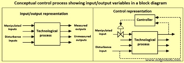
図1ブロック図に入出力変数を表示する概念的な制御プロセス
技術プロセスは、定常状態で動作することはめったにないため、本質的に動的です。技術プロセスの運用は、継続的に発生する障害に対して適切な対応が行われるようにすることで構成され、運用は安全で効率的であり、必要な速度で指定された品質の目的の製品を生成します。製造方法はプロセスごとに異なるため、自動制御の原理は本質的に一般的であり、プロセスのサイズやタイプに関係なく、普遍的に適用できます。プロセス制御システムの目的は、次のタスクのいずれかまたは両方を実行することです。
運用条件と設定値でプロセスを維持します –多くのプロセスは、定常状態で、またはコスト、歩留まり、安全性、その他の品質目標などのすべての要件を満たしている状態で動作する必要があります。多くの実際の状況では、プロセスは常に静的であるとは限らず、プロセスに障害が発生してプロセスが不安定になります。安定していないプロセスでは、プロセス変数は限られた時間内にその物理的境界から振動します。制御されていないプロセス変数は、自動的に、またはオペレーターの介入によって、制御限界内でプロセス変数を制御できる制御機器および機器を追加するだけで制御できます。
プロセスをある運用条件から別の運用条件に移行する –実際の状況では、さまざまな理由でプロセスの動作条件を変更する必要がある場合があります。あるセットの操作条件から別のセットの操作条件にプロセスを移行する理由は、経済性、製品仕様、操作上の制約、環境規制、および製品仕様の変更などが原因である可能性があります。
技術プロセスの制御戦略の開発は、(i)制御目的、(ii)操作変数または外乱変数のいずれかであり、連続的または離散的な時間間隔で変化する可能性のある入力変数を定式化または特定することで構成されます。 (iii)測定変数または非測定変数のいずれかであり、連続的または離散的な時間間隔で測定できる出力変数、(iv)ハードまたはソフトのいずれかである制約、(v)バッチである可能性のある動作特性、連続的または半連続的、(vi)安全性、環境、および経済的考慮事項、および(vii)コントローラーが本質的にフィードバックまたはフィードフォワードできる制御構造。技術プロセスのプロセス制御システムの策定は、7つの段階で構成されます。
制御システムを開発する最初の段階は、制御目標を策定することです。技術プロセスは通常、いくつかのサブプロセスで構成されます。各サブプロセスの制御を個別に検討すると、技術プロセスの制御が低下します。それでも、各サブプロセスには複数の、場合によっては競合する目標が含まれる可能性があるため、通常、制御目標の開発は困難な問題です。
第2段階は、入力変数の決定を構成します。入力変数は、プロセスに対する周囲の影響を示します。これは通常、プロセスに影響を与える要因を指します。入力変数は、操作変数または外乱変数として分類できます。操作された入力は、制御システム(またはプロセスオペレータ)によって調整できる入力です。外乱入力は、プロセス出力に影響を与える変数ですが、制御システムでは調整できません。測定可能な外乱入力と測定不可能な外乱入力の両方が存在します。入力は連続的に、または離散的な時間間隔で変化する可能性があります。
第3段階は、出力変数の決定を構成します。出力変数は、制御変数とも呼ばれます。これらは、周囲に影響を与えるプロセス出力である変数です。出力変数は、測定変数または非測定変数として分類できます。測定は、継続的に、または個別の時間間隔で行うことができます。
第4段階は、操作上の制約の決定を構成します。すべてのプロセスには特定の操作上の制約があります、 ハードまたはソフトに分類されます。ハード制約の例は、バルブが完全に閉じた状態または完全に開いた状態の両極端の間で動作する最小または最大の流量です。ソフト制約の例は製品の構成であり、特定の制限の間で構成を指定することが望ましいですが、安全性や環境上の危険をもたらすことなく、この仕様に違反する可能性があります。
第5段階は、動作特性の決定を構成します。動作特性は通常、バッチ、連続、または半連続に分類されます。連続プロセスは、比較的一定の動作条件下で長期間動作し、その後、クリーニングや定期的な予防保守などの特定のジョブを実行するために「シャットダウン」されます。バッチプロセスは本質的に動的です。つまり、通常は短時間動作します。期間と動作条件は、その期間中にかなり変化する可能性があります。バッチプロセスの例は、製鋼炉での加熱です。バッチ反応器の場合、反応器に初期投入が行われ、プロセス条件が変化して、バッチプロセスの最後に所望の生成物が生成される。典型的な半連続プロセスは、反応器への初期充填を有することができるが、供給成分は、バッチ運転の過程で反応器に追加することができる。連続鋳造プロセスは、半連続プロセスの例です。重要な考慮事項は、プロセスの主要なタイムスケールです。連続プロセスの場合、これは多くの場合、反応器内の材料の滞留時間に関連しています。
第6段階は、安全、環境、および経済の問題に関する重要な考慮事項です。ある意味で、経済学は究極の原動力です。なぜなら、安全でない、または環境に危険なプロセスは、規制上の罰則と非効率性のために、最終的には運用コストが高くなるからです。さらに、仕様を満たす製品を製造する際には、エネルギーコストを最小限に抑えることが重要です。より優れたプロセスの自動化と制御により、プロセスは「最適な」条件に近づいて動作し、変動性の仕様が満たされる製品を製造できます。
「フェイルセーフ」の概念は、計装の選択において常に重要です。一例として、コントロールバルブには、バルブステムを動かして流れを変えるためのエネルギー源が必要です。ほとんどの場合、それは空気圧信号です(通常は3〜15 PSI)。信号が失われると、バルブステムは3PSIの限界に達します。バルブが「エアツーオープン」の場合、計装用空気が失われるとバルブが閉じます。これは「フェールクローズ」バルブと呼ばれます。一方、バルブが閉じる空気である場合、機器の空気が失われると、バルブは完全に開いた状態になり、これは「フェールオープン」バルブと呼ばれます。
(i)フィードフォワード制御と(ii)フィードバック制御の2つの標準制御タイプがあります。フィードフォワードコントローラーは外乱変数を測定し、この値をコントローラーに送信します。コントローラーは操作変数を調整します。フィードバック制御の目的は、制御変数を設定値に近づけることです。フィードバック制御システムは、出力変数を測定し、その値を目的の出力値と比較し、この情報を使用して操作変数を調整します。その設計により、フィードバックコントローラは偏差を減らすために是正措置を取ります。フィードバックコントローラーは、制御変数が目的の設定値から逸脱し、ゼロ以外のエラーを生成した後にのみアクションを実行できます。ただし、プロセスまたは測定の変化が非常に遅い場合、外乱への応答は非常に遅くなる可能性があります。このような状況では、フィードフォワードコントローラーによってパフォーマンスを向上させることができます。フィードフォワードコントローラーは、外乱が制御変数に与える影響を予測し、外乱の影響を打ち消す制御アクションを実行します。
プロセスのフィードバック制御構造の決定は、どの操作変数を調整してどの測定変数を制御するかを決定することで構成されます。測定されたプロセス出力の望ましい値は、セットポイントと呼ばれます。制御変数が設定値から外れる理由は2つあります。設定値は、パフォーマンスを向上させるために意図的に変更されます。または、外乱によって操作が目的の設定値から離れます。外乱を排除するように設計されたコントローラーはレギュレーターと呼ばれ、設定値の変化を追跡するように設計されたコントローラーはサーボ機構と呼ばれます。通常、連続プロセスの場合、設定値の変更はまれにしか発生しません。通常、監視コントローラーがより好ましい動作点を計算する場合にのみ発生します。したがって、レギュレーターが使用されるフィードバックコントローラーの最も一般的な形式です。対照的に、サーボ問題のコントローラーは、設定値が頻繁に変更されるバッチプロセスでは一般的です。
制御システムの設計で使用される特に重要な概念は、「プロセスゲイン」です。 「プロセスゲイン」は、プロセス入力の変化に対するプロセス出力の感度です。プロセス入力の増加がプロセス出力の増加につながる場合、これは正のゲインとして知られています。一方、プロセス入力の増加がプロセス出力の減少につながる場合、これは負のゲインとして知られています。 「プロセスゲイン」の大きさも重要です。
制御構造が決定したら、制御アルゴリズムを決定することが重要です。制御アルゴリズムは、測定された出力変数値(および目的の出力値)を使用して、操作された入力変数を変更します。制御アルゴリズムにはいくつかの制御パラメーターがあり、許容できるパフォーマンスが得られるように調整する必要があります。多くの場合、調整は、実際のプロセスに制御戦略を実装する前に、シミュレーションモデルで行われます。モデルベースの制御の場合、コントローラーには「組み込み」のプロセスのモデルがあります。
単一の操作変数と単一の制御変数を使用した技術プロセスのブロック図(図2)には、フィードフォワード、フィードバック、および監視制御が含まれています。フィードバックコントローラの主な目的は、ある機器によって測定された制御変数Xを目的の設定値Xspにできるだけ近づけることです。制御変数は、技術プロセスの任意のパラメーターにすることができます。セットポイントは通常、リアルタイムの数値最適化手法を使用した監視制御システムによって決定されます。最終制御要素にはいくつかの異なるタイプがあります。負荷変数とも呼ばれる外乱変数Dは、制御変数をその設定値から逸脱させる可能性があり、目的の動作点に戻すために制御アクションが必要になります。フィードバック制御とフィードフォワード制御の両方で、外乱の影響を減らすことができます。それぞれの方法には、独自の長所と短所があります。外乱は、外部環境変数を含むさまざまな原因から生じる可能性があります。いずれの場合も、外乱変数はプロセスのコントローラーの影響を受けることはありません。制御変数Xとその設定値Xspの間の誤差または偏差Eは、フィードバックコントローラーへの入力です。フィードバックコントローラーは、誤差を減らすために操作変数Mを変更します。典型的な技術プロセスでは、そのような制御ループが多数存在する可能性があります。
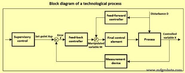
図2技術プロセスを制御するためのブロック図
ハードウェアとソフトウェアの制御
プロセス産業で実践されているプロセス制御は、1940年代に最初に導入されて以来、大きな変化を遂げてきました。 1960年代初頭、電気アナログ制御ハードウェアが空気圧アナログ制御ハードウェアの多くに取って代わりました。ただし、多くのプロセスでは、特定の制御要素、つまり制御バルブアクチュエータは、今日でも空気圧のままです。 1960年代の電気アナログコントローラーはシングルループコントローラーであり、各入力はプロセスの測定ポイントからほとんどのコントローラーが配置されている制御室に最初に送られました。次に、コントローラーからの出力が制御室から最終制御要素に送信されました。オペレーターインターフェースは、シングルループコントローラーとインジケーター用のディスプレイフェースプレートとチャートレコーダーの組み合わせを備えたコントロールパネルで構成されていました。制御戦略には、主にフィードバック制御が含まれ、通常は比例積分(PI)コントローラーを使用します。 1950年代後半から1960年代初頭にかけて、直接デジタル制御(DDC)と監視プロセス制御を実行するプロセス制御コンピューターが導入されました。 DDCを使用する場合、DDCループには100%に近いアナログ制御のバックアップが含まれることが多く、システムのコストが高くなります。
他の初期のシステムは、主に監視プロセス制御にプロセス制御コンピュータを使用していました。規制管理は、バックアップを必要としないアナログコントローラーによって提供されましたが、オペレーターの注意は、コントロールパネルとコンピューター画面の間で分割されました。ターミナルディスプレイは、監視制御が使用されているときにオペレータインターフェイスを提供しましたが、アナログバックアップが必要なときのために、コントロールパネルは制御室に配置されていました。この環境では、フィードフォワード制御、多変数デカップリング制御、カスケード制御などの高度な制御技術が広く使用されていました。これらの初期制御システムの機能は、プロセスの特性ではなく、コンピューターの機能を中心に設計されました。これらの制限は、不十分なオペレータートレーニングと不親切なユーザーインターフェイスと相まって、操作、保守、および拡張が困難な設計につながりました。さらに、多くの異なるシステムにはカスタマイズされた仕様があり、非常に高価になっています。プロセス産業へのデジタルシステムアプリケーションの注入は、安価なマイクロプロセッサが市販された1970年頃に行われました。
分散制御システム(DCS) – DCSは、図3に示すように、多くの要素で構成されています。ホストコンピューターは、最適化や高度な制御戦略など、計算量の多いタスクを実行します。デジタル伝送リンクで構成されるデータハイウェイは、システム内のすべてのコンポーネントを接続します。冗長なデータハイウェイは、データの損失の可能性を減らします。オペレーター制御ステーションは、プロセスを監視および制御するために、システムとのオペレーター通信用のビデオコンソールを提供します。多くのコントロールステーションには、アラームロギング、レポート印刷、またはプロセスグラフィックのハードコピー用のプリンタが含まれています。リモートコントロールユニットは、PIDアルゴリズムなどの基本的な制御機能を実装し、データ取得機能を提供する場合があります。プログラマーコンソールは、分散制御システム用のアプリケーションプログラムを開発します。大容量記憶装置は、管理目的および企業の意思決定のためにプロセスデータを保存します。大容量記憶装置は、ハードディスクまたはデータベースの形式にすることができます。コントローラ、入力、および出力間の通信と相互作用は、ハードワイヤリングではなくソフトウェアによって実現されます。したがって、DCSは、制御室の外観から高度な制御戦略の広範な使用に至るまで、プロセス制御の多くの側面に革命をもたらしました。
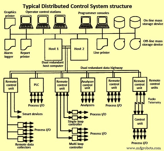
図3DCSシステムの典型的な構造
プログラマブルロジックコントローラー(PLC) –当初、PLCコントローラは、シーケンスとインターロックのための単純なバイナリロジックを実行する専用のスタンドアロンのマイクロプロセッサベースのデバイスでした。 PLCにより、このようなロジックに変更や変更を簡単に実装できるようになりました。 PLCは、計算機能の点でますます強力になっています。バッチプロセス制御はロジックタイプの制御が主流であり、PLCはDCSの代替として推奨されます。 DCSとPLCの間で比較的スムーズな統合インターフェイスが利用できるため、現在の慣例では、一般にDCSとPLCの統合された組み合わせを使用します。ほとんどのPLCはシーケンシャルロジックも処理し、アクションを所定の時間遅延させたり、アクションを所定の時間実行したりするための内部タイミング機能を備えています。
安全およびシャットダウンシステム –プロセス制御は、プロセスの安全性を考慮する上で重要な役割を果たします。自動化された手順が日常的な操作の手動手順に取って代わる場合、危険な状況につながる人為的エラーの可能性は低くなります。また、現在のプラントの状態に対するオペレーターの認識が向上します。危険なeプロセスに対して保護システムを提供する必要があります。 1つの方法は、安全インターロックシステムと呼ばれる、この状態が存在できない状態にプロセスを移行するという特定の目的のためのロジックを提供することです。プロセス制御システムと安全インターロックシステムは異なる目的を果たすため、物理的に分離する必要があります。これにより、安全システムを意図せずに変更するリスクが軽減されます。三重モジュール冗長システムなど、安全シャットダウン用に特別な高信頼性システムが開発されました。これにより、システムに内部障害が発生しても、基本的な機能を実行できます。基本的に、トリプルモジュラー冗長システムは、同じ機能を同時にアクティブに実行する3つの同じサブシステムで構成されます。
アラーム –アラームの目的は、即時の注意が必要なプロセス状態をプロセスオペレータに警告することです。異常状態が検出され、アラートが発行されると、アラームがアクティブになります。異常状態が解消されると、アラームは正常に戻ります。アラームは、測定変数、計算変数、およびコントローラー出力で定義できます。さまざまなクラスのアラームが存在します。
スマートトランスミッター、バルブ、フィールドバス –プロセス制御テクノロジーには、デジタルテクノロジーの使用の増加に向けた明確な傾向があります。デジタル通信は、フィールドバス、つまり同軸ケーブルまたは光ファイバーケーブルを介して行われ、インテリジェントデバイスが直接接続され、制御室またはリモート機器室との間でデジタル信号として送信されます。フィールドバスアプローチにより、ツイストペアおよび関連する配線の必要性が減少します(図4)。
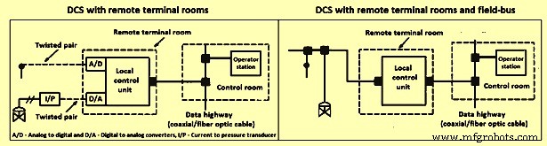
図4リモートルーム端末とフィールドバスを備えたDCS
さまざまなフィールドネットワークプロトコルは、フィールドデバイス、機器、および制御システム間でデジタル情報と命令を転送する機能を提供します。フィールドバスソフトウェアは、コンポーネント間の情報の流れを仲介します。複数のデジタル機器を接続し、デジタル通信回線を介して相互に通信できるため、配線が大幅に削減されます。
プロセス制御ソフトウェア –最も広く採用されているユーザーフレンドリーなアプローチは、フォームへの入力またはテーブル駆動型のプロセス制御言語(PCL)です。一般的なPCLには、ファンクションブロックダイアグラム、ラダーロジック、およびプログラマブルロジックが含まれます。これらの言語の中核は、アナログ入力、デジタル入力、アナログ出力、デジタル出力、PIDなどのいくつかの基本的な機能ブロックまたはソフトウェアモジュールです。一般に、各モジュールには1つ以上の入力と出力が含まれます。プログラミングには、グラフィカルユーザーインターフェイスを介してブロックの出力を他のブロックの入力に変換することが含まれます。ユーザーは、入力値のソース、出力値の宛先、およびモジュール用に準備されたフォーム/テーブルのパラメーターを示すために、テンプレートに入力する必要があります。ソースと宛先のブランクは、必要に応じてプロセスI / O(入力/出力)チャネルとタグ名を指定できます。モジュールを接続するために、一部のシステムでは、データを発信または受信するモジュールのタグ名を入力する必要があります。ユーザー指定のフィールドには、特殊機能、セレクター(最小または最大)、コンパレーター(以下)、およびタイマー(アクティブ化遅延)が含まれます。ほとんどのDCSでは、機能ブロックを作成できます。
施設管理階層 –さまざまな最適化、制御、監視、およびデータ取得アクティビティが使用される技術プロセスの5つのレベルを図5に示します。図の各ブロックの相対位置は、重複する可能性があるため、概念的なものです。実行される機能。各レベルがアクティブである相対的な時間スケールも表示されます。 5つの概念的な制御レベルにはそれぞれ、ハードウェア、ソフトウェア、技術、およびカスタマイズに関する独自の要件とニーズがあります。情報は階層内を上に流れ、制御の決定は下に流れるため、特定のレベルでの効果的な制御は、懸念のレベルより下のすべてのレベルが正常に機能している場合にのみ発生します。最高レベル(計画とスケジューリング)は、供給とロジスティクスの制約を満たすために生産目標を設定し、時変能力と人員利用の決定に対処します。これは、エンタープライズリソースプランニング(ERP)と呼ばれます。
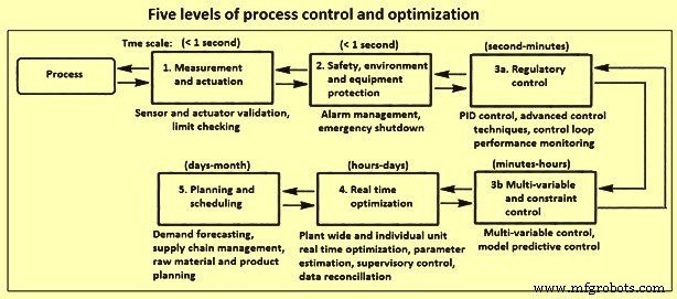
図5プロセス制御と最適化の5つのレベル
一般に、さまざまなレベルの制御アプリケーションは、次の目的の1つ以上を目的としています。つまり、(i)実用的な最適動作点でのプロセスの決定と維持、(ii)人員と機器の保護のための安全な操作の維持、(iii )オペレーターの注意と介入の必要性を最小限に抑え、(iv)動揺と妨害の数、範囲、および伝播を最小限に抑えます。
計装 –それは制御うんちのコンポーネントで構成されています。プロセスと制御階層の間の直接インターフェースを提供するインストルメンテーションは、プロセスの状態に関する基本的な情報源と、修正アクションがプロセスに送信される最終的な手段として機能します。プロセス測定デバイスの機能は、プロセス変数の値または値の変化を検知することです。実際の検知デバイスは、物理的な動き、圧力信号、ミリボルト信号などを生成できます。トランスデューサは、測定信号をある物理的または化学的量から別の量に変換します。たとえば、圧力をミリアンペアに変換します。変換された信号は、伝送線路を介して制御室に送信されます。したがって、送信機は信号発生器であり、ラインドライバです。最新の制御機器は、ディスプレイと制御アルゴリズムにデジタル信号を必要とするため、アナログ-デジタルコンバーター(ADC)は送信機のアナログ信号をデジタル形式に変換します。
最も一般的に測定されるプロセス変数は、温度、流量、圧力、レベル、および組成です。必要に応じて、他の物理的特性も測定されます。特定のアプリケーションに適した計装の選択は、関係する流体または固体の種類と性質、関連するプロセス条件、必要なレンジアビリティ、精度、再現性、応答時間、設置コスト、保守性と信頼性などの要因に依存します。
信号の送信と調整 – A wide variety of phenomena are used to measure the process variables required to characterize the state of a process. Because most processes are operated from a control room, these values are to be available there. Hence, the measurements are usually transduced to an electronic form, most often 4-20 mA, and then transmitted to a remote terminal unit and then to the control room. It is especially important that proper care is taken so that these measurement signals are not corrupted owing to ground currents, interference from other electrical equipment and distribution, and other sources of noise.
Final control elements – Good control at any hierarchial level needs good performance by the final control elements in the next lower level. At the higher control levels, the final control element can be a control application at the next lower control level. However, the control command ultimately affects the process through the final control elements at the regulatory control level, e.g., control valves, pumps, dampers, louvers, and feeders etc.
Process dynamics and mathematical models – A thorough understanding of the time-dependent behaviour of the technological processes is required in order to instrument and control the process. This in turn requires an appreciation of how mathematical tools can be employed in analysis and design of process control systems. There are several mathematical principles which are utilized for the automatic control. These are (i) physical models and empirical models, (ii) simulation of dynamic models, (iii) Laplace transforms, transfer functions, and block diagrams, and (iv) fitting dynamic models to experimental data etc.
Feed -back control systems – Measurements of the controlled variable are available in many process control problems. Specifically, this is the case when temperatures, pressure, or flows are to be controlled. In these situations the controlled variable can be directly measured and the manipulated variable is adjusted via a final control element. A feedback controller takes action when the controlled variable deviates from its set-point, as detected by the non-zero value of the error signal. The various types of feed-back controls are (i) on/off control, (ii) proportional control, (iii) proportional plus integral (PI) control, (iv) proportional plus integral plus derivative (PID) control, and (v) digital PID.
The simplest controller can only show two settings and is called an on/off controller. The output of this controller is either at its maximum or its minimum value, depending on the sign of the error. While this type of controller is simple, it is seldom used. The proportional controller offers more flexibility than the on/off controller because the manipulated variable is related not just to the sign of the error but also to its magnitude. The input-output behaviour of an actual proportional controller has upper and lower bounds i.e. the output saturates when the control limits are reached. Standard limits on the controller output are 3-15 PSI for pneumatic controllers, 4-20mA for electric controllers, and 0-10 VDC for digital controllers.
Integrating action needs to be included in the control loop, if an offset-free response in the presence of constant load disturbances or for set point changes is needed. If the process does not show integrating behaviour itself then it is possible to implement a proportional plus-integral controller to achieve the desired performance. There are both and disadvantages associated with integral action in a controller. One disadvantage of a PI controller is that the integral action can cause it to react more sluggishly than a proportional controller. If it is important to achieve a faster response which is to be offset-free then this can be accomplished by including both derivative and integral action in the controller. In order to anticipate the future behaviour of the error signal, a PID controller computes the rate of change of the error, thus the directional trend of the error signal influences the controller output. While many controllers have traditionally been analog PI/PID controllers, the trend towards digital control systems has also had an influence on controller implementation. In many modern process plants the analog PI/PID controllers have been replaced by the digital counterparts.
Open-loop and closed-loop dynamics – Open-loop dynamics refers to the behaviour of a process if no controller is acting on it. Similarly, if the controller is turned off by setting the proportional constant to zero, the control system shows open-loop behaviour and the system’s dynamics are solely determined by the process. Hence, it is not possible to reach a new set-point for a process in open-loop unless the input is changed manually. It is also not possible to reject disturbances when the process is operated without a controller.
The purpose of using closed-loop control is to achieve a desired performance for the system. This can result in the system being stabilized, in a faster system response to the set-point changes, or in the ability to reject disturbances. The choice of the controller type as well as the values of the controller tuning parameters influences the closed-loop behaviour. For a controlled process one needs to find controller settings which result in a fast system response with little or no offset. At the same time, the system is to be robust to the changes in process characteristics. Finding the appropriate settings is called ‘tuning’ the controller.
Controller tuning and stability – Finding of the optimum tuning parameters for a controller is an important task. Unsuitable parameters can result in not achieving the desired closed-loop performance (e.g. slowly decaying oscillations, or a slow acting process). It is also possible that a closed-loop process with a badly tuned controller can result in performance which is worse than for the open-loop case or that the process can even become unstable.
Mathematical software for process control – A variety of different software packages is available which support the controller design, controller testing, and implementation process.
Advanced control techniques
While the single-loop PI/PID feedback controller is satisfactory for many process applications, there are cases for which advanced control techniques can result in a significant improvement in closed-loop performance. These processes often show one or more of such phenomena as (i) slow dynamics, (ii) time delays, (iii) frequent disturbances, (iv) multi-variable interaction. A large number of advanced control strategies are being used. Some important ones are briefly discussed below.
Feed- forward control – One of the disadvantages of conventional feed-back control with large time lags or delays is that disturbances are not recognized until after the controlled variable deviates from its set point. However, if it is possible to measure the load disturbance directly then feed-forward control can be applied in order to minimize the effect which this load disturbance has on the controlled variable. In addition to being able to measure the load disturbance, it is also needed to determine a mathematical correlation for the effect which the load disturbance has on the controlled variable in order to apply a feed-forward controller. The reason for this is that the feed-forward controller inverts this model in order to cancel the effect that the disturbance has. A feed-forward controller can be designed either based on the steady-state or dynamic behavior of the process.
Cascade control – Another possibility of controlling processes with multiple or slow-acting disturbances, is to implement cascade control. The main idea behind cascade control is that more than just one controller is used to reject disturbances. Instead a secondary controller is added to take action before the slow-acting disturbance has an effect on the primary controlled variable. In order to achieve this, the secondary controller also requires a secondary measurement point which needs to be located so that it recognizes the upset condition before the primary controlled variable is affected. Cascade control strategies are among the most popular process control strategies.
Selective and override control – Some processes have more controlled variables than manipulated variables. Such a situation does not allow an exact pairing of controlled and manipulated variables. A common solution is to use a device called a selector which chooses the appropriate process variable from among a number of valid measurements. The purpose of the selector is to improve control system performance as well as to protect equipment from unsafe operating conditions by choosing appropriate controlled variables for a specific process operating condition. Selectors can be based on multiple measurement points, multiple final control elements, or multiple controllers.
Adaptive control and auto-tuning – Operating conditions of a process can frequently change during plant operations. This does lead to the process behaving differently from the model which has been used for the controller design. Hence, the controller does not have accurate knowledge of the process at the current operating point and hence cannot be able to provide adequate disturbance rejection or set-point tracking. One possibility to circumvent this is to use an adaptive control system which automatically adjusts the controller parameters to compensate for changing process conditions. Auto-tuning is a related method where the closed-loop system is periodically tested, and the test characteristics automatically determine new controller settings.
Fuzzy logic control – For many processes, it is very time consuming to determine accurate process models. However, at the same time, it can be intuitive to get a rough estimate of how the manipulated variable is to react to a process condition. For such a case, fuzzy logic controllers can offer an advantage over conventional PID controllers. The reason for this is that fuzzy controllers do not need an exact mathematical description of a process. Instead, they classify the controller inputs and output as belonging to one of several groups (i.e. low, normal, and high). Fuzzy rules are then used to compute the output category from the given inputs. These rules either have to be provided by the control engineer or they have to be identified from plant operations by auto-tuning. It is also possible to combine fuzzy logic controllers with neural networks in order to form neuro-fuzzy controllers. This type of controller can offer significant advantages over conventional PID when applied to non-linear systems whose characteristics change over time.
Statistical process control (SPC) – SPC, also called statistical quality control (SQC), has found widespread application in recent years due to the growing focus on increased productivity. Another reason for its increasing use is that feed-back control cannot be applied to many processes due to a lack of on-line measurements. However, it is important to know if these processes are operating satisfactorily. While SPC is unable to take corrective action while the process is moving away from the desired target, it can serve as an indicator that product quality might not be satisfactory and that corrective action are to be taken for further plant operations.
For a process which is operating satisfactorily, the variation of product quality falls within acceptable limits. These limits normally correspond to the minimum and maximum values of a specified property. Normal operating data can be used to compute the mean deviation and the standard deviation s of a given process variable from a series of observations. The standard deviation is a measure for how the values of the variable spread around the mean. A large value indicates that wide variations in the variable. Assuming the process variable follows a normal probability distribution, then 99.7 % of all observations is to lie within an upper limit and a lower limit. This can be used to determine the quality of the control. If all data from a process lie within the limits, then it can be concluded that nothing unusual has happened during the recorded time period, the process environment is relatively unchanged, and the product quality lies within specifications. On the other hand, if repeated violations of the limits occur, then the conclusion can be drawn that the process is out of control and that the process environment has changed. Once this has been determined, the process operator can take action in order to adjust operating conditions to counteract undesired changes which have occurred in the process conditions.
Multi-variable control – Many technological processes contain several manipulated as well as controlled variables. These processes are called multi-variable control systems. It is possible to analyze the interactions among the control loops with techniques like the relative gain array. If it turns out that there are only small interactions between the loops then it is possible to pair the inputs and outputs in a favourable way and use single loop controllers which can be tuned independently from one another. However, if strong interactions exist, then the controllers need to be detuned in order to reduce oscillations.
Model predictive control (MPC) – MPC is a model-based control technique. It is the most popular technique for handling multi-variable control problems with multiple inputs and multiple outputs (MIMO) and can also accommodate inequality constraints on the inputs or outputs such as upper and lower limits. All of these problems are addressed by MPC by solving an optimization problem and therefore no complicated override control strategy is needed. A variety of different types of models can be used for the prediction. Choosing an appropriate model type is dependent upon the application to be controlled. The model can be based upon first-principles or it can be an empirical model. Also, the supplied model can be either linear or nonlinear, as long as the model predictive control software supports this type of model.
Real-time optimization – Operating objectives for process facilities are set by economics, product orders, availability of raw materials and utilities, etc. At different points in time it can be advantageous or necessary to operate a process in different ways to meet a particular operating objective. A technological process, however, is a dynamic, integrated environment where external and internal conditions can cause the optimal operating point for each operating objective to vary from time to time. These operating points can be computed by real-time process optimization (RTO), where the optimization can be performed on several levels, ranging from optimization within model predictive controllers, to supervisory controllers which determine the targets for optimum operation of the process, to optimization of production cycles. The plant-wide problems which can be solved by optimization techniques on a daily or hourly basis can be large containing thousands or even tens of thousands of variables.
Batch and sequence control
In batch processes, the product is made in discrete batches by sequentially performing a number of processing steps in a defined order on the raw materials and intermediate products. Large production runs are achieved by repeating the process. The term recipe has a range of definitions in batch processing, but in general a recipe is a procedure with the set of data, operations, and control steps to manufacture a particular grade of product. A formula is the list of recipe parameters, which includes the raw materials, processing parameters, and product outputs. A recipe procedure has operations for both normal and abnormal conditions. Each operation contains resource requests for certain ingredients (and their amounts). The operations in the recipe can adjust set-points and turn equipment on and off. The complete production run for a specific recipe is called a campaign (multiple batches). A production run consists of a specified number of batches using the same raw materials and making the same product to satisfy customer demand. The accumulated batches are called a lot.
In multi-grade batch processing, the instructions remain the same from batch to batch, but the formula can be changed to yield modest variations in the product. In flexible batch processing, both the formula (recipe parameters) and the processing instructions can change from batch to batch. The recipe for each product must specify both the raw materials required and how conditions within the reactor are to be sequenced in order to make the desired product.
Batch process control hierarchy – Functional control activities for batch process control can be summarized in four categories namely (i) batch sequencing and logic control, (ii) control during the batch, (iii) run-to- run control, and (iv) batch production management.
In batch sequencing and logic control, sequencing of control steps follow the recipe involve. For example:mixing of ingredients, heating, waiting for a reaction to complete, cooling, or discharging the resulting product. Transfer of materials to and from batch reactors includes metering of materials as they are charged (as specified by each recipe), as well as transfer of materials at the completion of the process operation. In addition to discrete logic for the control steps, logic is needed for safety interlocks to protect personnel, equipment, and the environment from unsafe conditions. Process interlocks ensure that process operations can only occur in the correct time sequence for a prescribed period of time. Detection of when the batch operations are to be terminated (end point) can be performed by inferential measurements of product quality, if direct measurement is not feasible.
Run-to-run control (also called batch-to-batch) is a supervisory function based on off-line product quality measurements at the end of a run. Operating conditions and profiles for the batch are adjusted between runs to improve the product quality using tools such as optimization. Batch production management entails advising the plant operator of process status and how to interact with the recipes and the sequential, regulatory, and discrete controls. Complete information (recipes) is maintained for manufacturing each product grade, including the names and amounts of ingredients, process variable set points, ramp rates, processing times, and sampling procedures. Other database information includes batches produced on a shift, daily, or weekly basis, as well as material and energy balances. Scheduling of process units is based on availability of raw materials and equipment and customer demand.
Sequential function charts – Compared to a continuous process, batch process control requires a greater percentage of discrete logic and sequential control than regulatory control loops. Batch control applications is to control the timing and sequencing of the process steps based on discrete input and outputs as well as analog outputs. The complexity of the interactive logic within and between the various control levels, the required interactions with operators and the need for ongoing application modification and maintenance are reasons why organization, functional design, and clear documentation are so important to the successful use of batch control applications. In order to describe what is to be done, structural models are normally used to represent the required batch processing actions, the batch equipment, and the combination of components. Various formats have been proposed for describing the batch control applications, e.g., how the batch processing steps are carried out with the batch equipment and instrumentation, interfaces between the various levels of control, interfaces between the batch control and the operator actions and responses, and interactions and coordination with the safety interlocks. The formats proposed include flow charts, state charts, decision tables, structured pseudo-code, state transition diagrams, petri nets, and sequential function charts. A sequential function chart (SFC) describes graphically the sequential behaviour of a control program.
製造プロセス