


連続鋳造プロセスにおける電磁攪拌
連続鋳造プロセスでの電磁攪拌
溶鋼の連続鋳造工程では、鋳鋼製品の品質を向上させる方法が常に重要です。これは、プロセスの開発にとっても重要なままです。流れ制御技術としては、噴流角度の変更や水中入口ノズル(SEN)の形状の作り直しに加え、溶鋼と攪拌機を接触させることなく流体の流れを制御できる電磁技術を採用しています。電磁技術の1つのタイプは、リニア誘導モーターによって提供されるローレンツ力によって流体の流れを生成する電磁攪拌(EMS)です。 EMS技術は、鋼の連続鋳造で数年間使用されてきましたが、適用の効果と、液体コアを攪拌することによるその後の利点は、セクションサイズ、鋼種、および製品の適用に大きく依存します。
旧西ドイツのユンハンスの試験連続鋳造機で鋼に連続鋳造の原理が最初に適用されて以来、連続鋳造製品の品質はますます注目されてきました。近年、清浄な鋼の製造に重点が置かれているため、鋳造製品の微細構造および組成の均質化に対する要件が高まっています。化学組成、凝固条件、および金型内の溶鋼の流れの性質は、鋳造製品の表面品質と内部構造に影響を与えます。 EMS技術の適用は、ストランド内の等軸結晶ゾーンの形成を促進します。これにより、凝固構造が微細化され、介在物の含有量が減少し、鋳造製品の表面、表面下、および内部構造の品質が向上します。
連続鋳造プロセスでは、溶鋼が金型に注入されます。最終的な鋼製シェルは、金型で始まり、ストランドで続く凝固後に得られます。スターラーやブレーカーなどの電磁装置は、最終的な鋳造製品の品質と鋳造速度の両方を改善するために使用されるよく知られた技術です。微細構造と表面亀裂に関する最終シェルの主な欠陥は、主な原因のいくつかである温度変化、溶鋼の速度と圧力、自由表面の挙動、スラグの巻き込みなどの金型内の現象に直接関連している可能性があります最終製品の欠陥の。連続鋳造機でも使用されているもう1つのタイプの電磁装置があり、それは電磁ブレーキ(EMBR)と呼ばれています。このデバイスは主に金型に取り付けられ、線形EMSに似ていますが、交流ではなく直流があります。
EMSは、溶鋼の連続鋳造における凝固プロセスを制御するための直接的で強力な手法です。 EMSの唯一の利点ではありませんが、重要なのは、鋳造製品の中心線での構造と化学的性質の品質と均一性が向上することです。生産性の利点は、品質の向上を伴います。実験結果は、例えば等軸ゾーン幅を増やすことによって、鋼の微細構造に対するEMSからの有益な効果を示しています。 EMSを適用することで、ストランドのいくつかのタイプの欠陥の大きさを効果的に減らすことができます。気泡や気孔率もEMSの影響を大きく受けると予想されます。さらに、EMSは連続鋳造プロセスの歩留まりと生産性を向上させることが報告されています。
連続鋳造プロセスへのEMSの適用は比較的長い歴史があり、EMSの最初の試行は1960年代にさかのぼります。 EMSは、連続鋳造プロセスが鋼の工業生産を開始してから約10年後に連続鋳造機に導入されました。 EMSも介在物と気泡に影響を与えることが示されています。ストランドEMSは、1970年代後半に連続鋳造機へのEMSの実際の適用の扉を開きました。ストランドEMSの目的は、中心偏析を抑制する目的で高い等軸ゾーン比を取得することです。その後、固化したシェルへの非金属介在物やアルゴン気泡の閉じ込めを抑制し、鋳鋼製品の表面品質を向上させるために、インモールドEMS(図1)が開発されました。
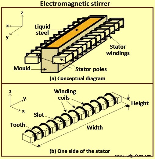
図1電磁攪拌機
連続鋳造プロセスの高い生産性を達成するために、EMBRは1980年代に開発され、連続鋳造金型内の溶鋼の流れを安定させました。最初のタイプのEMBRは、SENポートの近くに1対のDC(直流)磁石が取り付けられた局所磁場を作成することです。課されたフィールドは、SENからの排出された流れを直接「ブレーキ」します。 2番目のタイプのEMBRは、金型の幅方向に均一な磁場が磁場領域の下にプラグのような流れを発生させる水平磁場です。 EMBRの2番目のタイプの1つは、フロー制御(FC)金型です(連続鋳造金型の上部に一対の水平磁場を印加することで、金型の狭い面に沿ってメニスカスの流れと下降流を同時に安定させます。 )。現在、EMSとEMBRの組み合わせも開発されています。
プロセスを制御し、最終製品の欠陥を防ぐことを目的として、EMSやEMBRなどの電磁装置を使用してプロセスを改善しました。主な違いは、スターラーがAC(交流)電流の供給下で動作し、ダイナミクス磁場を生成することです。ブレーカーは、DC(直流)電流によって給電される永久磁石または回路です。したがって、それらは一定の磁場を生成します。違いはありますが、金属の流れに磁場を重ね合わせると、プロセス設計に従って流れを駆動できるローレンツ力が発生するという同じ考えに基づいています。金型で発生する物理現象は、液体の流れ、多相分析、電磁気計算、熱伝達、凝固プロセスなどのマルチフィジックスの問題であり、これらの各物理学は他の物理学に依存しています。
導体に印加される交番磁界(単相または多相)は、固体か流体かに関係なく、導体に電流を誘導し、したがってローレンツ力の分布を誘導することはよく知られています。このローレンツ力は一般に回転し、導体が流体の場合は動き始めます。したがって、磁場は非侵入型の攪拌装置として機能し、原則として、任意の所望の攪拌パターンを提供するように設計することができる。攪拌は、流体を介して駆動される定常電流分布と関連する磁場の相互作用によっても影響を受ける可能性があります。磁場周波数が高い場合、ローレンツ力は薄い電磁境界層に限定され、磁場の正味の効果は、境界層のすぐ内側に接線速度または接線応力のいずれかを誘発することです。速度または応力の分布は、加えられた場の構造に関連しています。対称構成は、流線がトロイダル表面上にある攪拌パターンにつながる可能性がありますが、より一般的には、流線パターンは無秩序です。
金型領域の流れは、ノズルと金型の形状、鋳造速度、ノズルの水没深さ、アルゴンガスの注入、および電磁力の適用によって制御されます。電磁力は、オプションで、ストランドの太さ全体に静磁場または移動磁場として適用されます。静的(DC)電磁場は、導電性溶鋼に電流を誘導し、それが流れに直接対抗する力を生成するため、「ブレーキ」または「EMBR」と呼ばれます。 EMBR磁場には、局所的な円筒形の磁場、金型幅全体にわたる広い「定規形」の磁場、および「フロー制御」または「FC型」磁場と呼ばれることもある二重定規磁場が含まれます。
>電磁力は、他の鋳造条件、ノズル、および金型の形状と組み合わせて、金型内の流体の流れを制御するための重要なツールです。方法には、静磁場(ローカルおよび定規EMBR)、およびEMS、マルチモードEMS、電磁レベル安定器(EMLS)、電磁レベル加速器(EMLA)などの時変磁場が含まれます。最適な使用により、流れが安定し、表面の欠陥が少なくなり、介在物が少なくなり、微細構造が改善されます。
移動(AC)磁場は、電磁攪拌(EMS)で発生します。この場合、いくつかの一連の磁気から磁場を位相シフトして、正味の磁場をストランドの反対側で反対方向に移動させると、通常は横断面で回転流が発生します。金型(M-EMS)または電磁回転攪拌(EMRS)。フィールドを同じ方向に移動させると、「マルチモードEMS」と呼ばれることもあり、加速流(EMLA)または減速流(EMLS)を誘発する可能性があります。誘導力は溶鋼の流れの強さによって変化するため、電磁力は他の流れ制御パラメーターよりも優れており、乱流の変化に対して自己安定化する理論的能力をシステムに与えます。実際には、これを達成するのは困難です。
EMSの原則
EMSはリニアモーターの原理を利用しています。溶鋼に部品が接触しない非接触攪拌機であるため、従来の機械式および減圧式とは異なります。図2aに示すように、炉の底部にコイルを設置すると、このコイル(インダクター)に3相のAC電圧が印加されると、移動磁場(H)が発生します。磁場の作用により溶鋼に電力が発生し、流れに誘導電流(I)が発生します(フレミングの右手の法則)。次に、この電流はインダクタの磁場と作用して、フレミングの左手の法則に従って溶鋼に電磁力(F)を誘導します。この力はローレンツ力として知られています。
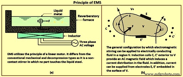
図2EMSの原理
回転式電磁攪拌機は、非同期モーター固定子に相当します。通常、3相または場合によっては2相の周波数変換器から供給されます。回転磁界が発生し、その液鋼内での変動により渦電流が発生し、それが磁界と相互作用して力(ローレンツ力)を発生させます。最終的な結果は、鋼の回転を誘発するトルクの発生です。発生するトルクは、(i)供給電流の強さ、(ii)コイルを形成する巻線の数、(iii)周波数、および(iv)システムの形状などのいくつかの要因に依存します。これらのパラメータは、スターラーのタイプM-EMS(モールド電磁スターラー)、S-EMS(ストランド電磁スターラー)、および(iii)F-EMS(最終電磁スターラー)によって異なります。
したがって、磁場は非侵入型の攪拌装置として機能し、原則として、任意の所望の攪拌パターンを提供するように設計することができる。スターラーの設計、サイズ、位置などは、連続鋳造機のデータ、製造される鋼種、および鋳造パラメーターによって異なります。
EMSシステムは、Bを誘導して回転する磁場を生成します。これにより、速度がvであるBに垂直な方向に渦電流jが誘導されます。誘導Bと電流jは、電磁力を生成します。この電磁力は、鋼の体積のすべての単位に作用します。溶鋼に攪拌運動を引き起こします。ベクトル積(v x B)は、電磁場と溶鋼の流れとの関係を示しています。 EMSによって引き起こされる溶鋼の速度は、毎秒0.1メートル(m / s)から1.0 m/sの範囲です。
磁場B(x、t)の存在下で、電流j(x、t)が固体または流体を問わず導電体を流れるとき、単位体積あたりの力F(ローレンツ力)が与えられます。導体に作用する式F=jxBによる。一般に、この力は回転します。つまり、カールFはゼロに等しくなく、導体が流体の場合、圧力勾配によって補償することはできません。このような状況では、流体は力に応じて移動する必要があります。これは、最も簡単な言葉で言えば、電磁攪拌の原理です。
表面Sで境界ボリュームVに閉じ込められた非圧縮性液体を考慮し、V+を外部領域とします。導体内では、Bとjはアンペールの法則(Mo)j =カールB、V x B =0によって関連付けられます。ここで、Mo =4(pi)x(10)-7(SI単位系)です。磁場はまた、外部ドメインV +のコイルに電流(ACまたはDC)などの外部ソースを持つことができます。考えられる通常の状況を図2bに示します。外部コイルC、C’の電流は、ファラデーの法則により、導体に電流分布を誘導します。この電流は、境界Sに埋め込まれた電極E、E’の間に電位差を直接印加することによって増大させることができます。したがって、電流は、時間依存磁場の印加、または電気的、あるいはその両方によって誘導できます。非常に広範囲の物理的条件と、特に冶金処理の分野での同様に広範囲のアプリケーションを検討できます。
これらのアプリケーションのいくつかは実用上非常に重要であり、EMSの基本原則が十分に理解されているという事実にもかかわらず、最も理想的な状況を除くすべての状況でEMSによって生成されるフローの理解はまだかなり原始的なレベルです。
EMSのカテゴリ
EMSは、鋳造機の設置場所に基づいて分類できます。セットアップ位置と冶金学的側面に応じて、すべての電磁攪拌機は3つのタイプに分類できます。鋳鋼製品の位置と必要な効果に応じて、これら3つの可能な攪拌機の用途は、(i)M-EMS、(ii)S-EMS)、および(iii)F-EMSです。 M-EMSは、その名前が示すように、金型内にあります。これは金型内攪拌です(一次EMSと呼ばれることもあります)。 S-EMSは、二次冷却領域の金型の下にあります。溶鋼の割合が高いのは、金型の下での攪拌です(二次EMSまたは金型下での攪拌と呼ばれることもあります)。 FEMSは、冶金学的長さの終わり(凝固が完了する直前)にあります。これは、最終凝固点(最終EMSと呼ばれる)の直前の攪拌です。図3は、3つの主要な攪拌タイプを示しています。
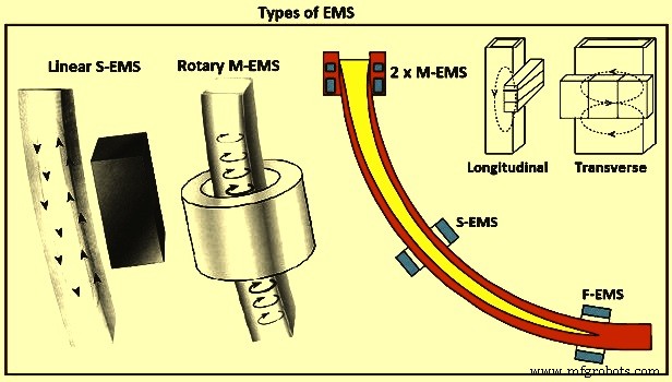
図3EMSの種類
M-EMS –ビレット/ブルーム攪拌装置を選択する場合、通常、ロータリータイプのM-EMSが最初の選択肢です。生成された回転磁界は、溶鋼内で円運動を起こします(図3)。回転流が柱状デンドライトの先端の破壊を促進し、それが中央ゾーンでの等軸結晶形成の核として機能するため、中央の等軸ゾーンが拡大されます。さらに、回転流が凝固前線を洗い流し、介在物や気泡が閉じ込められるのを防ぎます。さらに、発生した遠心力により、相が軽くなります(つまり、介在物と気泡が凝固前線から離れてストランドの中心に向かって移動します。
リニアM-EMSは、より大きな長方形のストランドセクションに使用されます。次に、2つのスターラーをキャスト製品の広い側面に沿って水平に配置します。この利点は、回転攪拌で得られるものと同様です。 M-EMSは伝統的に内部設計で金型に組み込まれ、金型でコイルがキャスターから取り外されていました。金型交換ごとに、電気ケーブルと場合によっては水ホースをコイルに接続/切断する必要がありました。新しい鋳造機は、コイルが金型の周りに構築され、金型交換中にキャスター内に残るという外部設計になっています。
M-EMSは通常、金型内の溶鋼を攪拌するために金型下部に設置されます。表面、表面下、および内側のストランドの品質を向上させます。 M-EMSを適用すると、鋳造製品のピンホール、中心気孔率、および偏析が減少します。凝固構造を改善し、表面粗さを低減し、熱伝達率を高めます。 M-EMSは円形または正方形の設計であり、内部または外部に設置できます。金型メニスカスの攪拌速度を柔軟に制御するために、デュアルコイルM-EMS(図6)が開発されました。デュアルコイルM-EMSは、2つの独立したEMSで構成されています。上部のEMSはメニスカスのフロー制御を目的としており、下部のEMSは金型内の主要金属の攪拌を実行します。メニスカス内の溶鋼速度の低下は、上部EMS磁場を下部EMSの磁場と反対方向に回転させることによって達成されます。このようなデュアルM-EMSの設計により、鋼の連続鋳造のさまざまな条件下でEMS技術を使用する機会が広がります。
S-EMS –リニアS-EMSでは、電磁コイルがストランドの片側に沿って取り付けられ、ストランド内に垂直循環液体金属フローパターンを生成します(図3)。スターラーはストランドの片側に沿って配置されているため、非常に異なるストランドサイズに使用できます。中央の等軸結晶ゾーンの増加は、ロータリースターラーと同じメカニズムで得られます。湾曲型連続鋳造機では通常上面近くの帯に集中する介在物もより均一に分布します。金型の下の高い位置に配置されたロータリーS-EMSは、ブレイクアウトの影響を受けやすくなっています。
S-EMSは、溶鋼を鋳造品の幅に沿って水平に押し出す攪拌力を発生させ、溶鋼にバタフライ型のフローパターンを生成します。 S-EMSをサポートローラーの後ろに配置できる場合(図4)、サポートローラーの最小直径に依存しないため、この場合、冶金学的観点からストランドに沿って最適に配置できます。 S-EMSをサポートローラーに組み込む場合、鉄心と巻線を含めるために最小ローラー直径が必要です。この場合、スターラーはメニスカスから離れた場所に配置されているため、効果が低くなります。 S-EMSは低周波数で動作し、ストランドを介したスターラー力の良好な浸透を保証します。その結果、溶鋼は図3に示すように横方向に攪拌されます。通常、S-EMSはM-EMSと組み合わせて使用されます。 S-EMSは、リニアタイプまたはロータリータイプのスターラーのいずれかです。最も一般的なのはリニアスターラーです。これは設置が簡単で、熱放射や発生の可能性から保護します。 S-EMSは等軸構造の形成を促進します。鋳造製品の結晶粒微細化を促進し、収縮キャビティ、中心偏析、および内部亀裂を低減します。また、過熱を効果的に除去します。
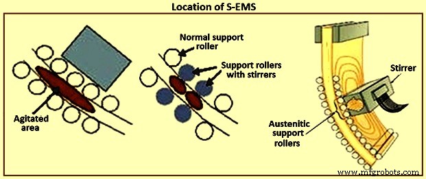
図4S-EMSの場所
F-EMS – EMSを使用して、連続鋳造ストランドの最終凝固ゾーンで金型のはるか下で攪拌することにも同様に強い関心があります。ただし、従来のEMSシステムは、この地域に適用するとやや効果がないことが証明されています。潜在的な解決策として、最近、変調されたローレンツ力を適用して、最終ゾーンで広く分布した激しい攪拌を開発することに大きな関心が寄せられています。 F-EMSは通常、M-EMSまたはS-EMSと組み合わせてインストールされ、中心分離のピークを低減およびカットします。 F-EMSは、高炭素鋼または高合金鋼のグレードを鋳造する場合に特に効率的です。また、F-EMSを使用することにより、鋳造品の凝固構造が改善され、等軸構造と内部気孔率の比率が増加することがわかります。収縮が減少し、中心炭素偏析の比率が減少します。さらに、二次デンドライトアーム間隔(SDAS)が改善され、中央の等軸粒子の比率が大幅に増加し、その結果、粒子が細かくなります。したがって、キャスト製品の品質はF-EMSで向上します。
基本的に、連続鋳造の「回転」攪拌と「上下」(または軸方向)攪拌に適用される攪拌には2つのタイプがあります(図5)。最近、これらのタイプの攪拌のいくつかのバージョンが多くの特許で提案されており、他の特許よりも洗練されているものもありますが、それらのすべてまたはほぼすべてが上記のカテゴリのいずれかに分類できます。
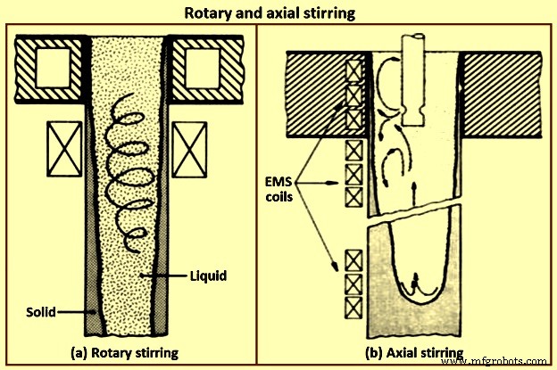
図5回転および軸方向の攪拌
EMSの電磁界は、リニアスターラー、ロータリースターラー、導電性スターラーの3つの方法で生成されます。リニアスターラーの磁極は直線上にあり、ロータリースターラーの磁極は円上にあります。線形および回転式電磁攪拌機はどちらもACを使用して、磁場と目的の効果を生成します。線形および回転電磁攪拌機は、鋼に電流を誘導します。一方、伝導性攪拌は、伝導電流と誘導電流を利用して、電磁場と目的の効果を生成します。ロータリーEMSは金型と二次冷却領域の両方に設置されますが、リニアEMSは主にS-EMSデバイスとして使用されます。導電性攪拌は、他の2つのモードと比較してニッチです。
回転攪拌 –回転攪拌に関する最初の作業は、オーストリアの研究者グループによって行われました。丸型で鋳造されたビレットは、型レベルまたは型のすぐ下で攪拌されました。確かに、金型は回転攪拌が理にかなっているかもしれない唯一の領域です。金型の下で回転式に実質的に攪拌すると、解決できるよりも多くの問題が発生する可能性があります。述べたように、型内のラウンドの回転攪拌にはいくつかのメリットがあります。鋳造物の表面から固体介在物が除去され、ストランドの固体スキンを金型とよりよく接触させることによって熱伝達が強化されます。金型内で回転攪拌して皮膚が破裂する心配はありません。しかし、回転攪拌の主な利点は、装置の設計が容易なことです。電気技師は、現在使用されているほぼすべての電気モーターと同じであるため、このタイプの電磁誘導運動に非常に精通しています。
回転運動は工学設計上の問題はありませんが、冶金学的観点からは最良の種類の運動ではない可能性があります。回転攪拌の基本的な問題の1つは、液体が遠心力にさらされることです。遠心力は、その軽い成分(たとえば含有物)を中心に向かって分離する傾向があります(図5)。これにより、液体の速度に上限が課せられますが、これは必ずしも「額縁」効果の出現によって設定された上限と同じではありません。シームレスパイプのラウンドをキャストする場合のように、これらの考慮事項を無視できる場合があります。ただし、もう1つの柔軟性のない制限は無視できません。液体の円速度を上げると、固体シェルへの圧力が不均衡に増加し、それが破裂する可能性があります。この危険性は、リン、セレン、鉛などの高度に分離する元素を含む鋼種を鋳造する場合に特に深刻です。これらの成分が形成する低融点の液体は、樹状突起間のスペースを占有し、シェルが持つことができる強度を低下させます。
金型の下で回転式に攪拌する場合、特に1つのレベルでのみ行う場合に発生する別の望ましくない状況は、液体プールを攪拌レベルより上の上部(高温)部分と下部の2つの部分に効果的に分離することです。 (コールド)攪拌レベルより下の部分。プール内の自然な流れを妨げることに加えて、この分割はブリッジングの問題を引き起こす可能性があります。次に、ブリッジングは、金型の下でのみ回転攪拌が適用された場合に最近報告されたいくつかの問題によって示されるように、マクロ分離を強化します。このような問題は、低速で攪拌するときに特に発生する可能性があります。攪拌領域のどろどろしたゾーンから分離された樹状突起の大きな断片は、攪拌の強度が低いため、サイズを小さくすることはできません。これらの大きな断片は、プールの下部(冷たい)部分に沈み、そこで成長してクラスターを形成し、ブリッジングを引き起こします。
回転攪拌には別の欠点があります。初期のデータは、EMSによって鋼の介在物のサイズと含有量を大幅に減らすために、液体の速度が特定の下限を超えることを示しています。たとえば、AISI 4335鋼種の場合、この制限は0.5 m / sを超えることが示されています。これは、きれいなスキンも生成される大きなインゴットのリミング動作中に発生する速度に匹敵します。安全な回転液体運動のための前述の上限が、介在物低減のための高速要件と矛盾することはほぼ確実です。同じことが、新しい凝固構造、すなわち繊維構造および流動修飾またはタムナイト構造を生成するためにも当てはまり、これらもまた高速を必要とする。品質全般、および誘導攪拌の新しい開発を積極的に追求してきた鉄鋼業界のセグメントは、すぐに高速攪拌によってこれらの構造を追求することができます。
軸方向の攪拌 –攪拌の軸方向または「上下」バージョンは、凝固ストランドの液体部分をストランドの軸に平行な方向に移動させるために提供されます。このタイプの誘導運動は、自然に発生する熱誘導された、対流パターン。金型領域では、自然な流れを逆転させる理由があります。鋼の連続鋳造では、金型領域は液体プールの小さな部分を構成し、15 m以上の深さになる可能性があります(機械の速度とサイズによって異なります)。型の下では、流れは固体スキンに隣接して「下」になり、ストランドの中央で「上」になります。
EMSの「アップアンドダウン」バージョンは、冶金学的観点から最も適切です。この手法では、液体の速度は実質的に無制限であり、必要な制御を適用するための十分な自由度があります。電磁的に誘発された力は、液体を固体の殻に押し付けるのではなく、液体を封じ込める傾向があるため、ブレイクアウトの危険性は最小限に抑えられます。他にも大きなメリットがあります。上部からの高温の液体はプールの下部にすばやく運ばれます。これにより、シェルの厚さがいくらか減少し、どろどろしたゾーン全体で温度勾配が高く保たれる傾向があります。これらの効果は両方とも熱流を改善し、それは次に連続鋳造機の生産性を高めるのに役立つ可能性があります。このバージョンのEMSで生産性を向上させる別の方法があります。ソリッドシェルの輪郭を変更して、丸い底を形成し、プールの深さを減らすことができます。これにより、キャスト速度を上げることができます。等温線が変化し、ストランドの中心での成長が上向きの成分を増加させるため、中心線の収縮と偏析の程度も減らすことができます。
最後に、悪名高いアルミナクラスターなどの凝固中に形成される介在物でさえ、固体に閉じ込められることは許可されていませんが、それらはスラグに結合する機会があるプールの上部にすばやく掃引されます(つまり、上に浮かんでいます)メニスカス)、したがって、排除されます。このタイプのフローは、特に冶金学的長さに沿ってかなりの部分に攪拌を適用する場合、つまり「上下」攪拌の連続バージョンの場合、実装がかなり困難です。ただし、この場合の問題は、問題の電気工学側にあることを強調しておく必要があります。コイル間またはリニアモーターを形成する一連のコイルの端に現れる大きな摂動なしに一方向の流れを実装することは比較的困難です。これらの異常は、正または負の分離のバンドとしてキャスト構造に反映されます。さらに、「上下」攪拌は通常、使用されるリニアモーターのフィールドに干渉しないように、サポートロールのないストランドのかなり広い領域、または少なくともロールの変更を必要とします。最後に、このタイプの攪拌に使用されるリニアモーターは、主に電磁ループの抵抗が高いため(大きなエアギャップと固体の金属スキンギャップ)、効率が非常に低くなります(1%以下のオーダー)。
断続的に攪拌を逆転させる –もともと一部の日本人研究者によって、回転攪拌モードのバリエーションが提案されました。この技術は、流れの方向を断続的に逆転させることを可能にし、それは、等軸ゾーンのサイズを改善すると主張されている。回転攪拌に関する上記の議論は、ここでも当てはまりますが、さらにいくつかの資格があります。断続的な動きはエネルギーを浪費しますが、EMSの1つの目的、つまり柱状の成長を妨げるという目的を達成することにはメリットがあります。攪拌中の流れを逆にすると、局所的な乱流セルでのせん断によってデンドライトが小さな断片に分解されるだけでなく、柱状デンドライトが常に流れ(上流)に成長しようとするため、柱状デンドライトの一方向の成長を妨げる可能性があります。ただし、この手法でEMSの他の可能な利点を引き出すことができるかどうかは疑わしいです。
鋳鋼製品の品質に対する電磁攪拌の影響
金型内の溶鋼の流れの化学組成、凝固条件、および性質は、本質的にストランドの表面品質と内部構造に影響を与えます。ストランド形成のプロセスには、金型内および二次冷却ゾーン(SCZ)での溶鋼の凝固が含まれます。回転または移動する磁場は、液体中の流れの性質に影響を与え、熱物質移動プロセスを強化します。ストランドの品質に対する電磁攪拌の影響の程度は、EMSの技術的特性と連続鋳造曲げ軸に沿った配置に依存します。 EMSは、金型、SCZ、および最終凝固ゾーン(FCZ)に正常に設置できます。
For improving the surface, subsurface, and inner strand quality, the liquid steel stirring has to take place in the mould. M-EMS is either of round or square design and it can be installed internally or externally. The result of applying M-EMS is a reduction in centre porosity and segregation in the cast product. To provide flexible control of stirring speed in the mould meniscus, the dual-coil M-EMS (Fig 6) has been developed. It consists of two independent EMS. The upper EMS is intended for flow control in the meniscus. The lower EMS performs the main metal stirring in the mould. The reduction in metal speed in the meniscus is achieved by rotating the upper EMS magnetic field in the opposite direction to that of the lower EMS. Such an M-EMS design widens the opportunities for using the technique under various conditions of continuous casting of liquid steel.
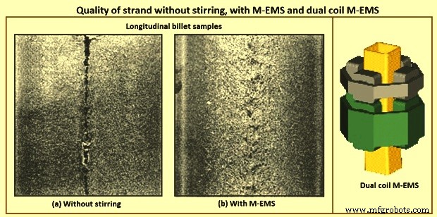
Fig 6 Quality of strand without stirring, with SMS, and dual coil M-EMS
The application of electromagnetic stirring of steels promotes the formation of an equiaxed crystallic zone in the strand. The stirring improves strand quality, even in steel casting with overheating. To further reduce and cut peaks in centre segregation, F-EMS, in combination with M-EMS or S-EMS, has to be used. F-EMS is particularly efficient when casting high carbon or high alloy steel grades. F-EMS and M-EMS combinations reduce the areas with the highest carbon content, where cementite and martensite otherwise can form. It has been found that stainless steels, solidifying with primary ferrite, have a sound centre at a reduction ratio of 3.6 when using S-EMS and F-EMS. The application of S-EMS increases the equiaxed crystallic zone instead of columnar structure and reduces cracks in the steel strand. The benefits available by using one or more EMS in combination are listed in Tab 1.
| Tab 1 Benefits available with using one or more EMS | ||||||
| M-EMS | M-EMS + F-EMS | M-EMS + S-EMS + F-EMS | M-EMS + S-EMS | S-EMS | S-EMS + F-EMS | |
| Pinhole and blowhole | +++ | +++ | +++ | +++ | – | – |
| Surface and subsurface cracks | +++ | +++ | +++ | +++ | – | – |
| Breakout reduction | ++ | ++ | ++ | ++ | +* | +* |
| Surface cracks (round) | ++ | ++ | ++ | ++ | – | – |
| Solidification structure and internal cracks | ++ | ++ | +++ | ++ | +** | +** |
| Centre line segregation, and centre porosity | ++ | +++ | +++ | ++ | ++ | +++ |
| V segregation | + | +++ | +++ | ++ | +*** | ++ |
| * S-EMS in high position | ||||||
| ** Better structure only in centre part of the product, after position of S-EMS, worse structure in external part compared to application of M-EMS. Risks of negative segregation when excessive stirring applied. | ||||||
| *** with S-EMS in low position | ||||||
For more demanding qualities the use of EMS can be justified when the costs of the quality defects, conditioning or rejections, or the costs of casting larger sections are too large. Rotary stirring is used for carbon steel with carbon less than 0.2 %. In some cases, in-mould stirring is preferred than the secondary stirring since in the secondary stirring the negative segregation is found. In-fact negative segregation does not have any effect on the mechanical properties but one minor exception is that it can cause local variation in the hardenability which is not appreciated. Carbon content between 0.2 % and 0.5 %, two-stage stirring is used. It is better to complement the in-mould stirring with the secondary stirring or final stirring. For carbon content higher than 0.5 % and alloy steels with a large solidification range, three-stage stirring is used.
Any benefits from EMS for slabs can be negated from the poor geometry. So, care is to be taken for the machining. Method of reducing submerged nozzle convection currents with the EMBR for improving cleanness. This consists of two sets of coils placed along the outer walls of the mould faces. The magnetic field reduces the liquid steel velocity and impurities float to the surface where they are trapped by the mould powder. The roll gap geometry of bloom casters and more considerably slab casters can have a major influence on the internal quality of continuous cast semis and on various types of segregation and consequently the increased levels of some elements in these segregated areas. The main types of segregation caused by deviations from the true roll gaps are (i) inter columnar macro segregation, (ii) centre line macro segregation, and (iii) off centre line semi macro segregation (also termed V segregation or spot segregation).
In the temperature range 1,300 deg C up to the solidus the ductility of steel is very low. This is due to the liquid phases of FeS and MnS which have segregated to the boundaries between dendrites. FeS and MnS both have melting points much lower than steel and hence these weak boundaries open at quite low tensile strains.
One of the metallurgical problems found in continuously cast products is the development of large columnar dendritic zones. The effect of columnar growth on the mechanical properties such as loss of ductility in steel has been investigated by Weiser. Alberney, have shown that centre line defects in the continuous casting can be considerably reduced by controlling the columnar growth regions. The control of columnar growth is crucial in producing good quality strand cast products.
Essentially, induction stirring causes a sweeping flow along the solid-liquid interface which affects the final solidification structure since it influences the local growth conditions such as the temperature gradient, the boundary layer thickness, and the structure and size of the ‘mushy zone’. Since macro-segregation is known to result from inter-dendritic fluid flow, reduction in the length of the ‘mushy zone is to effectively reduce the extent of macro-segregation, particularly along the centre line. Several studies have shown that EMS is an effective means of improving continuously cast steel solidification structures by preventing columnar growth.
The size of columnar zones and associated inter-dendritic segregation and shrinkage porosity are greatly reduced by the use of in-strand or in-mould electromagnetic stirring. The latter technique effectively increases the size of the equi-axed solidification zone and greatly reduces the amount of centre line shrinkage (Fig 6). The relative size of columnar and equiaxed zones in a cast cross section are also affected by superheating of liquid steel. High superheating in unstirred billets increases the size of the columnar zone because the nucleation of equiaxed dendrites is retarded. EMS reduces the effects of high superheats but does not completely compensate for the increased size of columnar zones developed by high superheat temperatures.
Superheat was one of the most fundamental factors recognized from the early years of continuous casting especially for medium and high carbon steels. In an early report, pilot plant tests were performed casting 150 mm x 150 mm billets of high carbon steels. It was proven that at low superheats or even sub-liquidus temperatures of casting, the centre line segregation was minimized. The electromagnetic stirring at the mould (M-EMS) exhibited some benefits, and the application of EMS at the strand (S) and final (F) stages of solidification started being installed in some casters. It was found that the combination of EMS, that is, (S+F)-EMS for blooms and (M+S+F)-EMS for billets, is the most effective method for reducing macro-segregation among various EMS conditions, causing them to solidify more rapidly during the final stages of solidification, providing more finely distributed porosities and segregation spots along the central region. The optimum liquid pool thickness was found to decrease as the carbon content increased, which can be attributed to longer solidification times in the solid fraction (fs) range from fs=0.3 to 0.7. The effect of superheat on the solidification structure has been analyzed, verifying the empirical fact that increasing superheat the columnar dendritic growth increases against the equiaxed one. They concluded that convection effects influenced micro-segregation behaviour of the studied high carbon (C less than or equal to 0.7 %), and high manganese steels.
The effect of F-EMS parameters with current intensity increasing from 300 A (ampere) to 400 A and frequency increasing from 4 Hz (hertz) to 12 Hz, on the electromagnetic forces and carbon concentration distribution in the central cross section of 70 steel square billet has been studied. The optimal F-EMS parameter to make uniform the central cross-sectional carbon concentration and minimize the centre carbon segregation of 70 steel billets has been obtained with a current intensity of 280 A and frequency of 12 Hz. Under this stirring parameter, the carbon segregation indexes for all sampling points are in the range of 0.92–1.05, which is attributed to the fact that its stirring intensity is more suitable for decreasing the strand centre temperature and increasing the solidification rate of the billet. Hence, the rejected solute element has limited time to transport after electromagnetic stirring which promotes the reduction of centre segregation.
It is well known that porosities and shrinkage cavity occur in the central part of continuous cast blooms and billets. Although there are good results in carbon segregation levels at a stirring current and frequency of 280 A and 12 Hz, respectively, further investigations have shown that the F-EMS has a considerable impact on the other internal qualities of a square billet.
The effect of F-EMS parameters on centre segregation was studied in 140 mm × 140 mm billet continuous casting process. In the model, the initial growth of equiaxed grains which can move freely with liquid was treated as slurry, while the coherent equiaxed zone was regarded as porous media. The results show that the stirring velocity is not the main factor influencing centre segregation improvement, which is more affected by current intensity and stirring pool width. Because solute transport is controlled by solidification rate as stirring pool width, centre segregation declines continuously with current intensity increasing. As liquid pool width decreases and less latent heat needs to dissipate in the later solidification, the centre segregation can be improved more obviously by F-EMS. Due to centre liquid solute enrichment and liquid phase accumulation in the stirring zone, centre segregation turns to rise reversely with higher current intensity and becomes more serious with stirring pool width further decreasing, it forms positive segregation and solute can be concentrate with weak stirring, leading to centre segregation deterioration. With the optimized current intensity, centre segregation improvement is better with respect to F-EMS.
Some F-EMS stirring techniques are more effective than others in terms of structure morphological transformation from original dendritic to globulitic and in its refining. Macrostructure of casts without the use of stirring is different from the one with the use of stirring. The structure can be obtained with conventional stirring is largely globule-shaped with some presence of dendrites and dendrite fragments. The structure obtained with modulated stirring consists of entirely globule-shaped crystals and structure appears to be more refined.
Grain size can be varied by applying different stirring setting. With F-EMS conventional stirring, the grain diameter is reduced in both cast mid radius and in central area with comparison with the unstirred structure. A further grain diameter reduction has been achieved with counter-rotating modulated and unmodulated stirring. However, the smallest grain diameter in the casts has been obtained with unidirectional modulated stirring, in comparison with the grain diameter in the cast without stirring.
In general, the microstructure of samples using F-EMS consists of globules and elongated grains in the structure obtained with stirring, and fine inter-granular eutectic network containing different compounds. The coarse dendritic structure of the cast products cast without stirring can be transformed into mainly globular one with some rosette shaped as a result of the conventional stirring application. The structure obtained with unidirectional modulated stirring consists of a mixture of fine round-shape globules and large elongated grains. This structure also appears to be more refined in comparison with that obtained with the conventional stirring.
The globule mean area and length in the microstructure of the combined mid-radius and centre area of the cast obtained with conventional stirring is when compared with the structure of the other casts. The globule mean area in the structure can be reduced, but not in case of structure obtained without stirring. The structure obtained with unidirectional modulated stirring in the casts, the globule mean area in these casts is reduced in comparison with conventional stirring. A similar trend is determined in reduction of the globule length. Concurrent with globule size reduction, their density has increased. The effect of the M-EMS on the solidification structures has been obtained under fixed superheat, casting speed, secondary cooling intensity, and M-EMS frequency. The ratio of the central equiaxed grain zone was found to increase with decreasing superheat, increasing casting speed, decreasing secondary cooling intensity, and increasing M-EMS current. But the equiaxed zone is limited for M-EMS, since it has more responsibility towards columnar zone. The grain size obviously decreased with decreasing superheat and increasing M-EMS current but was less sensitive to the casting speed and secondary cooling intensity.
White band segregation – The increasing use of electromagnetic stirring (EMS) over recent years has brought with it increased interest in the problem known as white bands. The white band is a zone of negative segregation (appearing white on sulphur prints) frequently found in S-EMS stirred products and corresponding to the position of the solidification front during stirring. The visual appearance of segregation has not only given rise to the name but is probably also the white band’s most undesirable feature. The extent of negative segregation at the white band is less than the positive segregation at the centre line, but it is continued presence after hot working can result in a deterrent to customer acceptance, mostly on cosmetic grounds. Kor has suggested an explanation, in which the white band is the result of changes in growth rate at the start and end of strand stirring. White band is due to the solute washing mechanism which was firstly found by Bridge and Rogers. This proposes that the turbulent flows caused by EMS penetrate the dendrite mesh and sweep out enriched inter-dendritic liquid (Fig 7). However, in order to maintain this action it is necessary to assume that the removed solute is very rapidly dispersed throughout the remaining liquid. This being so, it is difficult then to explain the observed solute enrichment at the end of stirring.
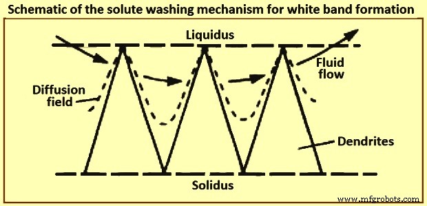
Fig 7 Schematic of the solute washing mechanism for white band formation
Mathematical modelling
In tandem, mathematical modelling has played an important role in the implementation of EMS, as regards to providing a deeper understanding of the effects of stirring on, for example, the heat and fluid flow. A series of studies by Schwerdtfeger and co-workers have formed the cornerstone of the modelling in this area. Specifically, they have explored, both experimentally and theoretically, the effect of stirring in the round billet, rectangular bloom and slab geometries which are characteristic for the continuous casting of steel. These models consist of the Navier Stokes equations for the velocity field of the liquid metal and Maxwell’s equations for the induced magnetic flux density. In principle, these are two-way coupled, since the alternating magnetic field gives rise to a Lorentz force which drives the velocity field. This, in turn, can affect the magnetic field. Moreover, the frequency of the magnetic field is typically large enough to allow the use of the time-averaged value of the Lorentz force as input to the Navier Stokes equations.
Recent study by Vynnycky revisited the problem of a rotary EMS applied to round-billet continuous casting and found that the method used originally to determine the components of the Lorentz force led to a non-unique solution. This has been a consequence of the fact that the normal component of the induced magnetic flux density, rather than the tangential ones, has been prescribed as the boundary condition. Moreover, since the normal component has been prescribed in models for the case of longitudinal stirring for rectangular blooms also, it is natural to expect non-uniqueness in those models too. Furthermore, since the expressions for the components of the Lorentz force are still frequently used, it is clear that a resolution of the issue is still timely, especially in view of modern-day interest in modulated EMS. In this case, magnetic fields of different frequencies are applied and it is the intention that the resulting Lorentz force is to have a constant time-averaged part and a time varying one. It goes without saying that posing the correct boundary conditions for the magnetic field is important for achieving meaningful results from modelling.
Since the early industrial implementation of EMS, it has been recognized that demanding steel grades, especially those with a wide solidification range, benefit from stirring both within the casting mould and also at a later solidification stage. This type of stirring, in continuous casting of liquid steel, became known as final solidification zone stirring or F-EMS. Despite early reports on F-EMS effectiveness with respect to improving the cast strand internal quality, especially the structural soundness and segregation, in the long run it has been realized that the metallurgical performance of F-EMS lacked in both the effectiveness and consistency, which can be attributed to a number of defining factors. First, it is important to position the F-EMS with respect to the solidification stage which corresponds to a certain solid fraction level in the melt volume. Second, the stirring at this solidification stage is being performed under conditions of progressively diminishing stirring torque and increasing melt viscosity. The former occurs due to a reduction of the stirring pool radius, while the latter is due to an increase in the solid fraction of the melt.
There is also an additional important factor impacting on the stirring effectiveness, arising due to the nature of the magnetic field used for stirring. The stirring systems currently employed in the production of continuously cast steel products are based on application of a rotating magnetic field (RMF). Such fields have limitations in their application at a later, or advanced, solidification stage, arising from the fact that the resulting angular velocity is very nearly constant with respect to radial position. This flow pattern is characterized by intensive shear force and turbulence at the solid-liquid interface which is highly effective in terms of dendrite fragmentation and the subsequent development of an equi-axial solidification structure, but has very little impact on mixing in the melt volume, especially near its central region. In contrast, intensive turbulence and mixing throughout the melt volume is required at a late solidification stage in order to disrupt formation of the crystalline network and, associated with it, the development onset of structural defects such as porosity, fissures, and solutal segregation.
There have been numerous developments aimed at improvement of the RMF based stirring at a later solidification stage through enhancement of the secondary fluid flow in the radial-axial plane. Hence, intermittent and alternating stirring schemes, both of which use sequential forced and dormant periods, have been introduced in the 1980s. Kojima and co-workers, demonstrated experimentally, while Davidson and Boysan confirmed theoretically that strong recirculatory flow occurs in the radial-axial directions during the dormant periods (i.e. without active stirring) due to the initial axial gradient of the swirl flow.
However, these stirring methods have not resulted in a considerable improvement of F-EMS performance. The reasons for that can be found in the recent study by S Eckert and co-workers who have shown that the occurrence of strong recirculatory flows is contingent on a provision of a narrow range of stirring and casting parameters. Non-compliance with those provisions can negatively impact on stirring performance and even render it useless or harmful. There have been several recent attempts to intensify turbulence and mixing in the bulk of the solidifying melt by using modulated electric currents to energize the stirring coils. The objective is to produce a modulated electromagnetic field which consists of both a time-averaged and a time-varying component. These recent developments have been theoretical and laboratory-scale in nature and none has been implemented into production practice. Counter-rotating magnetic fields have also been tested for stirring a solidifying aluminum alloy in laboratory experiments conducted by Vives. Considerable improvements in solidification structure have been achieved by using this stirring method.
Advantages of EMS
Advantages of EMS in the final product depend on the application and some examples are (i) better hot workability, during extrusion forging of the bars the frequency of internal failures is lower, (ii) improved shearing ability by avoiding the structure which causes cracks, (iii) improved hardenability because of improved homogeneity, (iv) improved wire rod drawing performances with a low frequency of cup and cone breakages, and (v) higher and more consistent fatigue properties of bars.
製造プロセス