


鋼の連続鋳造の自動化、計装およびモデリング
鋼の連続鋳造の自動化、計測、モデリング
溶鋼の連続鋳造プロセスは、溶鋼を固化して半製品(ビレット、ブルーム、ビームブランク、ラウンド、またはスラブ)にして、その後の圧延機での圧延を行うプロセスです。連続鋳造機の基本的な操作は、一次冷却ゾーン、スプレー冷却ゾーン、ストレートヘアアイロンなどの一連の操作を通じて、特定の組成の溶鋼を目的の形状とサイズのストランドに変換することです。
連続鋳造のプロセスは、基本的に(i)型の上に配置されたタンディッシュで構成され、鋼のティーミングレードルから溶鋼を受け取り、調整された速度で型に供給します。(ii)水で冷却された一次冷却ゾーン液体鋼がタンディッシュから供給され、二次冷却ゾーンに入るときにストランド形状を維持するのに十分な強度の固化した外鋼シェルを生成するための銅型、(iii)配置された封じ込めセクションに関連する二次冷却ゾーン型の下で、鋼ストランド(まだほとんど液体)が通過し、鋼ストランドをさらに固化するために水または水と空気の混合物(エアミスト)が噴霧されます。鋼ストランド、(v)凝固した鋼ストランドを除去のために所望の長さに切断するための切断トーチまたは機械的剪断機からなる切断セクション、および(vi)クーへのランアウトローラーテーブルベッドをリングするか、製品転送エリアに直接移動します。
鋼の連続鋳造プロセスは、熱伝達、溶鋼の凝固プロセス、溶鋼の流れ、および液体から固体への相転移に関連する問題を含む複雑な技術プロセスです。これは、溶鋼の連続鋳造プロセス中に発生する可能性のあるすべての物理化学的現象の影響を含む、最適なプロセス制御システムを作成するのにかなりの困難を伴います。このため、連続鋳造プロセスの制御は、製鋼プロセスで最も難しいタスクの1つです。
その複雑さによる連続鋳造プロセスには、いくつかの物理現象が伴います。金型内および金型を二次冷却ゾーンに置いた後の溶鋼凝固プロセスには、これらの重要な現象のほとんどがあります。一次冷却ゾーンで行われている部分的なプロセスは、(i)複雑な形状の領域を通る溶鋼の乱流と、対流によって引き起こされる水中の入口ノズルまたはシュラウド、(ii)溶鋼内の熱伝達です。面積、(iii)成形シェルと金型壁の間の金型内の熱伝達、(iv)固体および液体スラグの層を通る熱流、(v)熱応力の形成、(vi)関連する凝固シェルの収縮鋼の凝固プロセス中に発生する遷移、(vii)凝固現象に伴う熱効果、(viii)凝固ストランドに対する金型壁の機械的衝撃、(ix)金型壁と凝固の間のエアギャップ形成のプロセスストランド、および(x)元素分離効果を伴う凝固ゾーン内での結晶の形成。
表面欠陥の形成は、二次冷却ゾーンで発生します。このゾーンで行われているプロセスは、(i)液体コア領域内の熱伝達(伝導と対流)、(ii)凝固したシェル層の熱伝導、(iii)凝固現象に伴う熱効果、(iv)です。スプレーゾーンの数と適用される冷却タイプに関連する、ノズルシステムによるストランド冷却に起因する多段階熱伝達、(v)鋼の凝固プロセス中に発生する遷移に関連する凝固ストランドの収縮、(vi)個々の凝固ゾーン(樹枝状結晶のゾーンおよび等軸結晶のゾーン)の形成、および(vii)ロールとストランドの接触に関連する応力の形成、および連続鋳造機ロール間の膨らみの可能性。
鋼の連続鋳造の自動化、計装、およびモデリングには、いくつかの推進要因があります。これらの推進要因には、品質に対する顧客の要求の高まり、競争の激化、より厳しい環境規制、および安全要件の増大が含まれます。さらに、連続鋳造機の全体的な生産システムは、前後のユニットとのプロセスの一貫性を確保することです。さらに、連続鋳造プロセス自動化システムは、生産計画とスケジューリング、品質保証、およびより一般的な監督管理機能を含む重要なタスクを実行するためにも必要です。
連続鋳造プロセスのプロセス制御には、ストランド凝固プロセスを完全に制御するための精巧な機器が必要です。連続鋳造機の測定システムは、多くのプロセス情報を提供します。ただし、機械の個々のポイントでのシェルの厚さの変化や冶金学的長さ(液体コアの長さ)などの重要な情報が欠落しています。したがって、数学モデルは、連続鋳造プロセスの制御システムにとって非常に重要です。これらの数学的モデルの正確さにより、プロセス中に技術的な決定を下すために使用することができます。
自動化および計装システムと数学的モデルにより、連続鋳造製品の品質が向上および主張され、さまざまな方法で機械のダウンタイムが短縮されます。数学的モデルを組み込んだエキスパートシステムが開発されました。ますます高まる品質要求に起因する新しい課題と、連続鋳造プロセスのさまざまなよく知られた問題に取り組むための新しいアイデアにより、プロセスの自動化と制御にいくつかの進歩がもたらされました。
連続鋳造プロセス用の最新の自動化システムは、いくつかの数学モデルを使用して、鋳造プロセスのさまざまなフェーズをシミュレートします。これらの計算の入力データは、レベル1の自動化から特定のトランスポートアダプターによってリアルタイムで取得されます。鋳造プロセスのターゲットパラメータは、特定の生産プログラムまたはオペレーターによって指定されます。エキスパートシステムを使用して、プロセスパラメータの最適値を計算し、生産品質を制御し、技術プロセスのさまざまな状態のオンフライモデリングを実行し、ローラーとセグメントのセットアップをチェックします。エキスパートシステムはレベル2自動化の一部です。データ転送のための明確なソフトウェアアーキテクチャと安定したミドルウェアプラットフォームは、さまざまな自動化システム、エキスパートシステム、およびオペレーター間の相互作用を成功させるために重要な役割を果たします。
HMI(ヒューマンマシンインターフェース)は、製造プロセスを通じてオペレーターをガイドします。運用担当者のやり取りは、品質関連および安全関連の活動に限定されています。重要な情報の概要がメインディスプレイに表示され、専用画面の広範なセットから詳細に簡単にアクセスできます。オペレーター画面は、操作担当者が理解できる言語と単位で表示されます。システム全体は構成可能なアプリケーションのセットで構成されており、ユーザーは事前定義されたテキストを入力する代わりに選択できます。図は、連続鋳造プロセスの典型的な自動化システムを示しています。
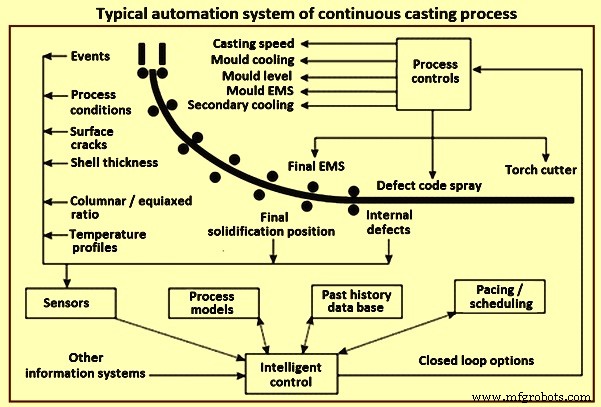
図1連続鋳造プロセスの典型的な自動化システム
自動化システムの階層
自動化システムの責任レベル、要件、および対応の次の分類は、連続鋳造機の技術プロセスの自動化および制御システムを設計および開発するときに定義されます。
レベル0の自動化 –それは個々のユニットの制御で構成されています。自動化された領域内の個々のユニットは、接続されたセンサー、トランスデューサー、回転トランスデューサー、ドライブ、制御、および制御回路を使用して制御されます。直接手動制御は、レベル0自動化システムによって順番に処理されるユニット、ドライブ、およびインターロックを介して実行されます。ほとんどの安全メカニズムもこのレベルで保存されます。
レベル1の自動化 – PLC(プログラマブルロジックコントローラー)制御を介してユニットのグループを制御します。 レベル1自動化システムによって処理されるタスクには、1つの自動化領域内の複数のデバイスの制御システムが含まれます。制御タスクは通常、PLCモジュールとマイクロコントローラーによってリアルタイムで実行されます。システム応答時間間隔は、PLC制御の場合は20ミリ秒(ms)から150ミリ秒、マイクロコントローラーの場合は10ミリ秒から20ミリ秒です(たとえば、モーションコントローラ)。これらのシステムの応答時間は厳しく制限されているため、複雑な生産プロセスモデルを実装することはできません。たとえば、モバイルユニットを使用した資材追跡やカバレッジ計画に関連するタスクは、他の自動化レベルに委任されます。
連続鋳造機のレベル1自動化機能には、通常、(i)タレット、ダミーバーカー、およびタンディッシュの制御、(ii)ダミーバーの位置の決定、(iii)ドライブローラーの調整、( iv)幅の調整、金型のテーパー、金型レベルの制御、および(iv)一次および二次冷却システムで選択した設定値に応じた空気と水の調整
レベル2の自動化 –レベル2の自動化は、プロセス制御用です。レベル2の自動化システムは、生産プロセスの効率と品質保証を決定する上で重要な役割を果たします。レベル2の自動化システムは、運用エンジニアまたは関連する標準によって事前に定義された指示と設定を使用して、鋳造プロセスを管理および監視します。さらに、各鋳造指示には、目標製品の品質を生み出すための最良の条件を示す一連の品質評価パラメーターが含まれています。一連の冶金モデルを使用することで、鋳造プロセスを完全に自動化でき、オペレーターの入力や介入の必要性を最小限に抑えることができます。プロセスモデルは、すべての学部を接続して、全体的なパフォーマンスの最適化を実現します。
レベル2自動化システムは、(i)生産品質の保証、(ii)プロセス制御とレベル1自動化システムへのコマンドとパラメーターの送信、(iii)自動化された生産データの取得、(iv)シミュレーション、技術プロセスの統合数学モデルを使用したシステム状態の予測、(v)材料追跡、(vi)モバイル機器を使用した材料処理およびカバレッジ計画システムの最適化、および(vii)生産の評価を含む警告および障害表示システム障害と設定時間。
連続鋳造プロセスのレベル2自動化システム要件には、(i)鋳造中のプロセスパラメータの収集と表示、(ii)ストランド、ストランド表面、およびエッジでの3D温度分布の計算(iii)が含まれます。ストランドシェルの成長、凝固長、エッジ収縮、スケール、およびその他の鋳造特性の計算、(iv)ストランド二次冷却システムの動的位置決め、(v)セグメントの動的調整の実行(ソフトリダクション)、(vi )材料の変化と凝固位置の追跡、および(vii)オペレーターの介入の受け入れと転送。
レベル2の自動化に通常含まれるプログラムとモデルには、(i)ストッパー機構を備えた溶鋼フロー制御、(ii)金型レベル制御、(iii)金型粉末レベル制御、(iv)鋳造の自動開始、( v)モールドブレイクアウト防止システム、(vi)モールド、ストランド、および最終攪拌、(vii)油圧モールド振動、(viii)ヒートトラッキングモデル、(ix)リアルタイム品質評価、(x)カット最適化モデル、( xi)リアルタイムストランド凝固モデル、(xii)オンライン/オフライン凝固曲線計算機、(xiii)動的機械的軟質還元、(xiv)動的二次冷却制御、(xv)鋳造製品マーキングマシン、(xvi)光学製品認識システム、(xvii)プロセス分析とシミュレーション、(xviii)冶金データ管理、(xix)生産遅延検出、(xx)機器寿命追跡、および(xxi)三次冷却を含む鋳造製品処理ロジスティクス。
連続鋳造プロセスにレベル2の自動化制御機能を実装する場合、複雑なデータ構造を使用して、ドメインのさまざまな専門用語をモデル化します。特に、スプレープラン、エアプラン、参照温度曲線、鋳造粉末、鋳造パラメータデータセット、鋼種、化学参照分析、鋼種グループ、亀裂、およびサンプルカットを使用した問題領域のマッピングをさまざまな角度から調べます。典型的な冶金学的問題に関して。さらに、数学モデル、制御メカニズム、およびユーザーインターフェイスには、連続鋳造プロセスの簡略化された標準化された記述が必要です。このプロセスでは、ストランドガイダンス、モールド、セグメント、ロールなど、計算に関連する実際のオブジェクトのプロパティが明確に定義されます。スプレーノズル、二次冷却制御回路、および冷却セグメント。言及されている用語は、簡潔なドメイン固有言語を導入することで簡単に説明できます。
連続鋳造の場合のレベル1またはレベル2の自動化システムのタスクは、常に明確に分類できるとは限りません。個々の自動化タスクの配置と分散に関する結論は、入力パラメーターとプロセスデータのローカリゼーション、組み込みモデルの可能な応答時間、必要なストレージスペース、および自律性の程度によって決まります。要件は、材料追跡などの2つのシステム間で頻繁に分散され、安全インターロックなどの一部は重複しています。どちらのシステムにも、通常はそれぞれの自動化レベルのタスク用に設計された独自のユーザーインターフェイスがあります。
レベル3 –レベル3の自動化は、生産計画用です。鋳造プログラム、作業のスケジュールと準備、店舗管理などの生産計画の生成、および保守計画、シャットダウン時間、保守タスクを扱います。
分散型レベル2自動化システムのソフトウェアアーキテクチャ –レベル2の自動化システムが満たす必要のある重要な要件は、統合された数学モデルと、レベル1の制御システム、レベル3の計画システム、接続されたデータベース、および連続鋳造機の操作担当者との安定した安全な通信です。 。レベル2の自動化の設計と構成では、さまざまなコンポーネント、それらのインターフェイス、および接続されたデータソースが重要であり、すべてのコンポーネントの動作ロジックを過小評価してはなりません。
レベル2自動化システムに統合された数学的生産プロセスモデルは、プロセス制御システムの中核を形成します。プロセスの実際のステータスを監視することにより、モデルにレベル1自動化システムからの実際の値を継続的に提供できます。一方、データには、短期計画の結果、およびレベル3自動化システムからの材料と注文のデータも補足されます。計算結果と製造工程の全体像は、ユーザーインターフェース上で操作担当者用の連続鋳造機に表示されます。運転員による必要なプロセス制御介入は、速度設定などのレベル1自動化システム入力マスクと、制御レジーム(基準温度およびスプレープラン制御)の変更などのレベル2自動化システムユーザーインターフェイスの両方を使用して実行できます。 。
このようなシステムの実装にはさまざまなソフトウェアアーキテクチャパターンが使用されます。これらには、モデル(マルチエージェントアーキテクチャ)、イベントおよびメッセージングディスパッチャ(イベント駆動型アーキテクチャ)、分散サービス(サービス指向アーキテクチャ)が含まれることがよくあります。
計装
器具は、連続鋳造の初期から連続鋳造機で使用されてきました。器具は、タレットまたは取鍋車と鋳造製品の振れローラーテーブルの間の連続鋳造機のすべての主要コンポーネントで使用されています。計器は、図2に示すように、取鍋、タンディッシュ、金型、二次冷却ゾーン、放射ゾーン、および振れローラーテーブルの変数を監視するために連続鋳造機で広く使用されています。制御鋳造パラメータは、連続鋳造機の生産性と品質で達成された大きな利益の主な要因の1つとして認められています。
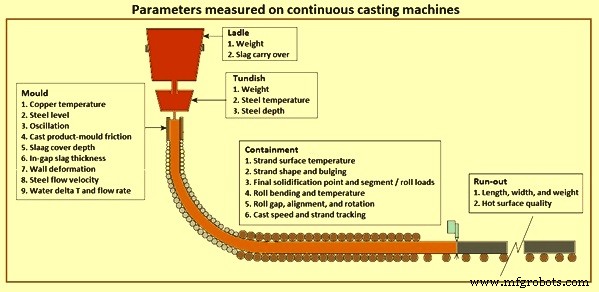
図2連続鋳造機で測定されたパラメーター
計器は、制御および自動化システムにとって非常に重要であり、最新の生産性および品質基準を達成するための計器の貢献を過大評価することはできません。計装は制御および自動化システムの「目」であり、現在の技術では、プロセスおよび品質管理システムで恒久的な計装を使用して、最も重要な取鍋、タンディッシュ、および金型の変数を「見る」ことができます。
連続鋳造プロセスにおける機器の主な機能は、(i)連続鋳造の機械的および冶金学的機能の性能を制御するために利用されるパラメーターを測定し、(ii)各鋳造セクションに品質評価を割り当てることです。(iii )操作と機械の問題を診断し、(iv)製品の品質と生産性を鋳造機の設計と操作に関連付ける知識を開発します。
連続鋳造機で使用される器具の数と洗練度は急速に高まっています。急速な成長の主な理由は、生産性の向上と鋳造製品の品質に対する要求の高まりと、最新のオンラインデジタルコンピューターの可用性です。これは、品質と生産性の要求が最も厳しいスラブ鋳造機に特に当てはまります。以前は、金型の慣行とパラメータが製品の品質と生産性に最も影響を与えるため、金型の計装に重点が置かれていました。しかし、最近、取鍋、タンディッシュ、封じ込め、および鋳造機のランアウトローラーテーブルでの計装の開発と適用において大きな進歩が見られました。
連続鋳造機の二次冷却ゾーンのスプレーチャンバー内に見られる危険な環境を考えると、鋳造機の制御システムが、ストランド表面温度などの重要なプロセス変数の変化に対して頻繁に「ブラインド」されることは驚くべきことではありません。ゾーン。ここで使用される計装は通常一時的なものであるため、実験的に使用されます。その他の重要な機器には、ロール間の膨らみ、固化したシェルの厚さ、および金型/ストランドの摩擦を測定するために使用される機器が含まれます。
連続鋳造プロセスのモデリング
鋼の連続鋳造のプロセスのモデリングは非常に複雑な作業であり、さまざまなタイプの数学モデルを使用して実行できます。現在、連続鋳造の全工程で発生するすべての効果を同時に捉え、単一の包括的な数値モデルの形で提示することはできません。連続鋳造プロセスモデリングに適用される自然分割は、溶鋼の実際の鋳造中に発生する問題を特定する試み、または既存の技術を改善するためにプロセスの選択されたセクションに焦点を当てる試みに関連しています。
問題解決の初期段階では、モデルタイプの正しい選択と、解決された問題のクラスへの適応のための関連する可能性は困難な課題でした。理論的には、より複雑なモデル(つまり、より「インテリジェント」)は、鋳造プロセスの主要な技術的パラメーターに関する質問に簡単に答えることができます。しかし実際には、いくつかの制限があります。複雑なモデルが正しいことが検証されたと仮定すると、最良の場合、計算時間の不必要な延長が必要になります。これは、モデルが定義された問題を解決するために必要なパラメーターよりもはるかに多くのパラメーターを計算するという事実に起因します。設定された問題の複雑さを使用されたツールの「インテリジェンス」と同期させないことによって引き起こされる2番目の危険は、モデルパラメータの検証とプロセスデータとの相関の問題です。モデルの精緻化が理論的であるほど、パラメーターが多くなり、測定不可能なパラメーターが発生するリスクが高くなります。最後のコメントは、必要なモデルパラメータの値の知識を取得する戦略の問題に関するものです。連続鋳造プロセスのモデリングにおける数年の経験は、最良の選択はすべての測定可能なモデルパラメータの実験的測定であることを示しています。これは、温度、鋼の熱伝導率、粘度などの関数として鋳造された鋼の比熱の形でパラメータによって説明できます。
物理モデリング –水を使用して溶鋼をシミュレートするなど、連続鋳造プロセスの物理モデリングにより、連続鋳造プロセス中の溶鋼の流動挙動をかなり詳しく知ることができます。連続鋳造プロセスにおける流体の流れについてのこれまでの理解は、主に物理的な水モデルを使用した実験を通じてもたらされました。この手法は、プロセスに実装する前に、新しい構成の効果をテストして理解するための便利な方法です。フルスケールモデルには、オペレーターのトレーニングと理解を提供するという重要な追加の利点があります。
物理モデルの構築は、対象となる重要な現象を支配する形状と力のバランスの両方を一致させることにより、モデルと実際のプロセスの間の特定の類似性基準を満たすことに基づいています。水モデルで溶鋼の流れのパターンを再現するために、支配的な力の間のすべての比率は、両方のシステムで同じでなければなりません。これにより、モデルと鉄鋼プロセスの速度比がすべての場所で同じになります。無次元グループのサイズは、2つの力の相対的な重要性を示しています。非常に小さいグループまたは非常に大きいグループは無視できますが、鋳造プロセスの中間サイズのすべての無次元グループは、物理モデルで一致する必要があります。これらの一致を実現するには、適切なジオメトリスケールと流体を選択する必要があります。
水と鋼の動粘度が非常に似ているのは幸いです。したがって、実物大の水モデルを構築することにより、レイノルズ数とフルード数を同時に一致させることができます。これらの2つの基準を満たすことは、連続鋳造ノズルや金型などの等温単相フローシステムのモデリングで妥当な精度を達成するのに十分であり、これは大きな成功を収めています。
実物大のモデルには、機械部品のテストとオペレーターのトレーニングが簡単であるという追加の利点があります。実際、両方のシステムの速度が完全な乱流と非常に高いレイノルズ数を生成するのに十分高い限り、任意の幾何学的スケールの水モデルは、ほとんどのフローシステムに対して妥当な結果を生成します。タンディッシュノズルとモールドノズルを通る流れは重力駆動であるため、フルード数は通常、油圧ヘッドと形状がすべて同じ量でスケーリングされるこれらのシステムの水モデルで満たされます。
物理モデルは、熱相似基準を満たす場合があります。たとえば、取鍋やタンディッシュ内の定常流の物理的流れモデルでは、修正されたフルード数のサイズで示されるように、熱浮力は支配的な慣性駆動流に比べて大きいため、モデル内で同じに保たれます。溶鋼システムのように。速度を推定するのが難しい取鍋では、レイノルズ数の2乗をグラスホフ数と呼ばれる修正フルード数で割ったものを調べると便利です。型では慣性が支配的であるため、熱浮力は無視できます。熱浮力の相対的な大きさは、実物大の温水モデルで一致させることができます。ただし、熱損失を支配する現象は、モデルと鋼製容器で異なる流体伝導率や比熱、容器壁伝導率などの特性に依存するため、これは簡単ではありません。低速、過渡現象、凝固などの他のシステムでは、熱伝達に重要な他のいくつかの相似基準を同時に満たすことは事実上不可能です。
図3に示すように、連続鋳造プロセスの複雑さとそれを支配する現象により、物理モデルを作成することは困難です。ただし、コンピューターのハードウェアとソフトウェアの能力が高まるにつれ、数学的モデリングは連続鋳造プロセスのすべての側面を制御するための重要なツールになりました。
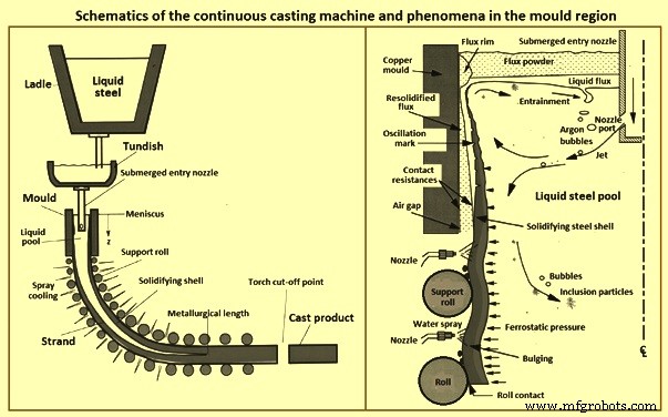
図3連続鋳造の概略図と金型領域の現象
計算または数学的モデリング –現在、計算コストの削減と商用モデリングパッケージの能力の向上により、溶鋼の連続鋳造プロセスの複雑な材料プロセスステップを理解するための追加ツールとして数学モデルを適用することが容易になっています。計算モデルには、等温水モデルでは困難な、熱伝達、粒子運動、二層流などの他の現象への拡張が容易であるという利点があります。計算モデルは、溶鋼が経験する流動状態をより忠実に表現することもできます。たとえば、ストランド水モデルを出る流れを妨げる物理的な底は必要なく、移動する固化シェルの存在を考慮に入れることができます。
数学モデルは、連続鋳造プロセスに重要な現象のほとんどをシミュレートできるようになりました。これらには、(i)複雑な形状(入口ノズルおよびストランド液体プール)での完全に乱流の一時的な流体の動き、アルゴン気泡、熱および溶質の浮力の影響、(ii)粉末相と鋼相内およびそれらの間の熱力学的反応が含まれます。 (iii)鋼の上面に浮かぶ液体および固体の流体層内の流れと熱の輸送、(iv)表面張力、振動、重力による影響を含む、自由な液体の表面と界面の動的な動き波、およびいくつかの段階での流れ、(v)乱流液体鋼を介した過熱の輸送、(vi)溶質の輸送(グレード変更中の混合を含む)、(vii)液体を介した複雑な形状の介在物の輸送、浮力、乱流相互作用、および介在物の閉じ込めの可能性がノズル壁、気泡、固化鋼壁、および上面に及ぼす影響、(viii)メニスカス領域での熱的、流体的、および機械的相互作用凝固メニスカス、固体スラグリム、浸透液フラックス、溶鋼、粉末層、および介在物粒子の間、(ix)凝固鋼シェルを通る熱輸送、シェルと金型の間の界面(粉末層と成長するエアギャップを含む) 、および銅型、(x)シェルと型の間のギャップを下る粉末の大量輸送、(xi)型壁およびサポートロールの歪みと摩耗、(xii)溶融物および型に対する固体結晶の核形成壁、(xiii)デンドライト、粒子および微細構造の成長、相変態、沈殿物形成、および微小偏析を含む鋼シェルの凝固、(xiv)熱収縮、相変態および内部による凝固鋼シェルの収縮応力、(xv)外力(金型摩擦、サポートロール間の膨らみ、引き抜き、重力)による凝固鋼シェル内の応力発生、(xvi)熱ひずみ、クリープ、およびプラ微視的および巨視的スケールの両方で、(温度、グレード、および冷却速度によって変化する)ticity、(xvii)亀裂形成、および(xviii)結合分離。
連続鋳造プロセスの驚異的な複雑さにより、これらすべての現象を一度にモデル化することは不可能です。したがって、合理的な仮定を立て、重要性の低い現象を切り離すか無視する必要があります。定量的モデリングでは、関心のある特定の問題に影響を与えるすべての現象を組み込む必要があります。したがって、各モデルには特定の目的が必要です。支配方程式が選択されると、それらは通常、有限差分法または有限要素法を使用して離散化および解かれます。適切な数値検証を実施することが重要です。
数値エラーは通常、非線形方程式を解くときに計算領域が粗すぎるか、収束が不完全であるために発生します。既知のテスト問題を解決し、メッシュの改良研究を実施してグリッドに依存しないソリューションを実現することは、モデルの検証に役立つ重要な方法です。最後に、モデルは、パラメトリック研究の実際のプロセスの定量的予測を行うために信頼できるようになる前に、実験室とプラントの両方のスケールでの実験測定値に対してチェックする必要があります。
モデルの最終テストは、結果を実装でき、鉄鋼製品の欠陥の回避などの改善を達成できるかどうかです。この実装には、最終的にプラントの試験が必要です。試験は、物理モデル、数学的モデル、文献、および以前の経験を含む、利用可能なすべてのソースから提供された洞察に基づいて実施されます。計算能力の向上が数値シミュレーションツールの機能を向上させ続けるにつれて、モデリングは、ハイテク連続鋳造プロセスへの将来の進歩においてますます重要な役割を果たします。 Modelling can augment traditional research methods in generating and quantifying the understanding needed to improve any aspect of the process. Areas where advanced computational modelling plays a crucial role in future improvements include (i) transient flow simulation, (ii) mould flux behaviour, (iii) taper design, (iv) on-line quality prediction and control, especially for new problems and processes such as high-speed billet casting, thin slab casting, and strip casting.
Future advances in the continuous casting process are not going to come from models, experiments, or plant trials. They are going to come from ideas generated by people who understand the process and the problems. This understanding is rooted in knowledge, which can be confirmed, deepened, and quantified by tools which include computational models. As the computational tools continue to improve, their importance is increasing in fulfilling this important role, leading to future process advances.
The assumed computing objective and the required accuracy are to be the key in selecting the model. In several cases, the desired information is knowledge of the metallurgical length of the strand and the dynamics of changes in the shell thickness. This is the case when determining a place for carrying out the so‐called soft reduction operation. As can happen when the strand casting speed needs to be changed, a procedure allowing a new cooling intensity to be determined is needed. A problem like this does not need answering a series of questions related to stress occurring in the strand, the structure formed, or potential cast strand defects. Thus, it is understandable that the model is naturally simplified to a form, which still provides a credible answer to the questions which needs solution.
Some of the important models used in the automation and control of the continuous casting process are given below. The models are normally incorporated at the Level 2 automation level.
Dynamic secondary cooling control – There is a third dimension in the dynamic secondary cooling control. The model set up takes the precision and control possibilities to the next dimension allowing completely new philosophies for secondary cooling and soft reduction. When setting up the secondary cooling system, it is prerequisite to consider all known parameters which have a known influence to the calculation of 3-dimensional temperature profile of the strand. All different nozzle types are measured at the nozzle test stand to evaluate the spray water distribution. This derived information is input to the maintenance and setup system (MSS) of the 3D model. The visualized spray distribution can be seen in the maintenance system.
The exact positions of the nozzles in the cooling zones are entered and the spray distribution of one zone can be seen in the MSS. The heat removal of a cooling zone is calculated considering the heat removal of the spray water, rolls, and heat radiation. The MSS allows all cooling-relevant settings to be configured in such a way that the spray-water distribution in the cooling zones and the application of cooling practices are optimized for continuous casting machines. Metallurgical know-how can be easily incorporated into the automation setup. A built-in off-line simulation system enables comprehensive testing of new parameter settings prior to application in the production process.
The Level 2 automation system for secondary cooling provides a mathematical model for calculating the temperatures on the strand surface and inside the strand as a function of the spray plan to be used, the interpolation points in the reference temperature curve, or in relation to time changes for the spray water quantities across the complete machine. The dynamic secondary cooling control system can handle three control regimes namely (i) temperature control, (ii) strand age, and (iii) spray plan control.
In the temperature control regime the dynamic secondary cooling control system calculates the volumes of water for strand secondary cooling which are needed to maintain the specified reference temperature on the strand surface. The strand age regime is one way of controlling the secondary cooling process, taking into account the change in parameters over a given period of time. With the spray plan control regime a spray plan is produced for secondary cooling whereby preset spray water volumes correspond to a specific casting speed. As the change in casting speed takes effect, the spray water volumes are also immediately modified, and the resulting temperatures on the strand surface are displayed to the continuous casting machine operator. If temperature scanners are used in the plant, the dynamic secondary cooling control system is able to adapt to the values delivered by the scanners, so that the coefficients of the strand temperature field calculation can be adapted to the values measured.
Dynamic 3D secondary cooling system – The first-generation dynamic solution was characterized by a two-dimensional temperature calculation of the strand centre. The strand corners were largely neglected by the process model. Continuous improvements in computer performance have now made it possible to calculate the temperature at any point within the entire strand in real time, in a full three-dimensional mode and in a sufficiently fine discretization yielding very detailed temperature profiles as can be seen for strand surface and strand centre.
The model is based on an explicit finite-volume approximation which solves the heat transfer equation and takes into consideration temperature-dependent material properties such as density as well as the position-specific cast product thickness and width. Dynamic 3D secondary cooling system accurately assesses the heat transfer from the cast product surface resulting from radiation, heat transfer to the rolls, natural convection and spray water. Further, the dynamic 3D secondary cooling system can be applied for both spray cooling and air-mist cooling and takes into account the spray distribution pattern of the nozzles and the actual spray water temperature. This ensures an accurate spray-cooling heat transfer prediction to temperatures below 700 deg C when the Leidenfrost phenomenon disappears. The result is an even more precise determination of the strand surface-temperature profile and the final point of strand solidification.
Based on the precise temperature calculations the dynamic 3D secondary cooling system allows specifying the desired surface temperature not only along the strand length, but also across the strand width. Even individual control of the water flow and positioning of each cooling nozzle is possible. The control algorithms of the dynamic 3D secondary cooling system calculate the water flow set-points to achieve the target strand surface temperature values. Pyrometer measurement results show an excellent fit in between calculated and measured lateral strand temperature profile.
Application of the dynamic 3D secondary cooling system allows introducing completely new philosophies to set up cooling practices for upcoming challenges in continuous casting. The combination with moveable spray nozzles (3D sprays) yields unprecedented quality results.
The advanced secondary cooling dynamic 3D model derives correct water flow rates even in transient casting situations such as steel grade changes, casting speed variations, different tundish temperatures, tundish exchanges, and at the beginning and end of a casting sequence. The water flow rate for each cooling zone is calculated to maintain a defined surface temperature profile throughout the entire casting sequence. The maintenance system allows the process engineer to change cooling practices easily and introduce continuous casting shop specific cooling expertise. The off-line simulation system is used to test the effect of the new settings in various casting situations before utilization in the production process.
Dynamic phase calculation of material properties – In order to calculate a 3-dimensional temperature profile of the strand, material properties like enthalpy, solid fraction, density, and conductivity as a function of the temperature are to be known. In case, these properties are experimentally known for a given steel grade composition, these functions can be entered by the process engineers in the MSS, which is very time-consuming. Normally the process engineer does not know these thermo-physical properties. The software model calculates all the thermo-physical data used by 3D model. Dynamic phase calculation of material properties is available as an on-line tool to determine the material properties for the current steel grade analysis.
The traditional approach is to define the thermo-physical properties for grade groups with a pre-defined concentration range of the chemical analysis. Using the dynamic phase calculation, these data can be calculated for each individual steel grade. This makes the prediction of quantities such as the point of complete solidification on the strand and the temperature distribution of the strand during casting more accurate and hence allows for precise metallurgical treatments which can lead to an improved quality of the products. Further, the model indicates whether the current analysis of the steel is peritectic or not and alerts the operator in the event of an unexpected peritectic grade. This can reduce the risk of breakouts and improves quality.
The dynamic phase calculation is based on thermodynamical models. The liquid-solid phase transformation in the high temperature range is described by a Gibbs free energy model in combination with a micro-segregation model. For solid-solid phase transformations in the low temperature range an Avrami type model is employed. The free parameters of the models are determined with the help of experimentally measured quantities. Using off-line simulations of dynamic phase calculation together with the 3D model allows metallurgical development of new steel grades.
Traditionally the steel grades are grouped and a typical chemical analysis for the group is used to determine the material properties. With dynamic phase calculation, the material properties are derived from the actual steel analysis. Calculations can show that there can be a difference in the point of final solidification of half a meter or even more by comparing the results of the actual steel analysis versus the grade group analysis. This fact shows the importance of having an on-line calculation of the actual steel grade in order to improve the quality of the cast products.
Dynamic gap soft reduction – Dynamic gap soft reduction stands for dynamic roll-gap adjustment in the continuous casting process. This is made possible by specially designed strand-guide segments – known as ‘smart segments’ in which the roller gaps can be remotely adjusted for strand thickness changes and for improved internal strand quality. On the basis of the on-line information provided by the dynamic 3D thermal-tracking model, the dynamic gap soft reduction dynamically calculates the set points of the adjustable roll gap.
Supervision of the roll engagement, depending on the state of solidification (liquid, mushy, or solid) and the calculated strand-thickness profile, is a decisive factor for precise roll adjustments and thus improved product quality. An optimized roll engagement also reduces excessive forces on the strand and decreases roller wear. The more accurate control of the roller gaps allows additional casting strategies to be implemented such as liquid-core reduction and intentional bulging soft reduction.つまりintentional dynamic gap increase before the soft reduction area allows for higher thickness reduction in this area. This further improves the casting flexibility and the product quality.
Dynamic gap soft reduction makes it possible to freely define scenarios for start-up, tundish change, and tail out strategies based on the strand thickness, steel grade, and casting status. In this way roll damage and production interruptions, which can arise from the different casting behaviour of the cold strand head or end, can be avoided.
Nozzle expert for early clogged nozzle detection – Cooling water is sprayed through nozzles onto the strand with the objective of achieving uniform cooling of the steel. However, if one or more of these nozzles are clogged, then a section of the strand cannot be uniformly cooled to the required temperature. This can lead to surface defects, and the cast product possibly has to be down-graded. The issue of changing segments in the continuous casting machine is also a source of difficulty. Hoses can easily be ruptured or jammed. Aware of the consequences of leakages or clogged nozzles, maintenance personnel spend a large number of working hours checking whether nozzles are operating properly.
The nozzle expert helps to detect clogged nozzles and broken hoses in the continuous casting machines and thus ensures that the strand is evenly cooled for high quality steel production. It automatically monitors the condition of the nozzles during the casting process. The model can also be manually activated during casting breaks. The advantage is that nozzle status can be checked following maintenance work or segment changes and immediately repaired before the casting process is restarted.
The model calculation considers parameters like nozzle type (measuring results from the nozzle test stand), height between pressure measuring device, water pressure, pipe lengths, pipe diameters, and nozzle positions. Any modifications to the secondary cooling system e.g. use of different nozzle types needs a change in the set-up of the nozzle expert in order to get correct computational results.
The nozzle expert is based on statistical models and indicates the clogging ratio in each zone (e.g., zone 2 nozzles clogged 10 % with a probability of 96 %). Operators need only to inspect zones for which an alarm is generated. Calculations begin automatically with the start cast signal, and the condition of the nozzles is monitored throughout the casting process. Several alarms help to detect leakages, clogged nozzles, and even falsely installed nozzles on a segment.
Inter-mix expert – It improves yield by prior simulations. During sequence casting, a mixing of steel grades takes place in the tundish and therefore in the strand with each ladle change. On the basis of the chemical composition of the steel, the inter-mix expert calculates whether the mixed steel zones can be used for the foreseen product application or if the steel has to be downgraded or even scrapped. Information acquired from tundish flow experiments combined with analysis results of steel samples taken from solidified products ensures a high degree of accuracy of Inter-mix predictions with respect to the actual composition of the mixed steel zones.
The inter-mix expert determines traces of the previously cast heat present in the current heat. Steel mixing takes place not only in the tundish but also in the mould and upper parts of the strand. Mixing in these areas is evaluated by a mix-box-type sub-model of inter-mix which makes it possible to calculate the chemical composition of the steel at any position along the cast strand.
Tundish changes or the use of separator plates are treated individually. Inter-mix calculations are cyclically performed for selected chemical elements starting with the ‘ladle open event’ of a new heat. The final decision about the compatibility of heats cast in sequence is performed by the heat-assignment function of inter-mix. The concentration profiles of certain critical elements which have an impact on the final product disposition (prime, downgraded, or outright rejection) are determined. A deviation is detected if one of the critical elements does not match the steel-grade specification.
The full benefit from the inter-mix model is achieved by combining the model output with the yield expert model which assures maximum prime quality yield by applying cut-length optimization to incompatible steel areas along the strand which are designated as scrap.
Process engineers work with the powerful simulation environment, which makes it possible to simulate any combinations of different steel grades. Input parameters like analysis, tundish weight, and dimensions of the strand can be easily entered and modified and the computed results are made visible in the HMI. Graphs are displayed for single analysis elements or combinations of more elements. Valuable information like volume concentration, mixed steel length, scrap length, and heat ranges on the strand are shown on the bottom of the graphs.
Configuration of the model can be easily done in the MSS. The process engineer can choose which chemical elements are to be used to determine the inter-mix for any grade link. A powerful simulation environment allows simulating the mixing behaviour of two different grades and the computed volume concentration, calculated analysis along the strand, and heat ranges including possible scrap sections are displayed.
Speed expert – The speed expert model is for the optimum casting speed in any casting situation. Selection of a proper casting speed on the continuous casting machine is of high importance. Several aspects (e.g. quality, safety, machine limits, and production requirements) influence the choice of the casting speed. These different aspects are frequently contradictory such as increase in production calls for a high casting speed whereas the safety requirements limit the casting speed. Normally, several continuous casting shops have self-made software solutions to calculate the casting speed considering different aspects. The aim of the speed expert is to cover most aspects and to provide an easy maintenance tool which enables the process engineer to adjust the behaviour of the speed expert to the special needs.
The speed expert calculates cyclically the optimum casting speed. The calculation of the casting speed is based on various rules, which consider the different aspects and are specified in the speed expert practice. Each rule determines a speed range which satisfies its requirements. The speed expert first determines the inter-section of all these speed ranges. If the inter-section is not empty, then it selects a casting speed depending on the predefined strategy, which can be maximum speed, aim speed, or avoid speed changes as long as actual casting speed is in the valid range. If there is a conflict between the different rules, then the inter-section is empty. In this case the pre-selected conflict resolve strategy is applied which can be (i) priority (lower priority rules are to be neglected till a solution can be found), or (ii) minimum of maximum speed (the smallest of all maximum speeds is to be selected).
On the on-line HMI the casting machine operator can view the speed ranges of all rules and the derived optimum casting speed. The casting operator can change the priorities of the different rules, the strategy, and the conflict resolve strategy to fine adjust the calculation if necessary. Speed set-points are sent to Level 1 and can be executed automatically.
MSS is used to define the speed expert practice considering (i) quality related rules consisting of quality expert rule, minimum / aim / maximum speed for the steel grade, superheat, Mn/S ratio, low tundish weight, and optimum soft reduction, (ii) production related rules consisting of heat pacing, start cast, and clearing, and (iii) safety related rules consisting of machine protection, and forecast calculation for minimum and maximum speed.
Optimum soft reduction can be achieved if the final point of solidification is at the end of a strand segment. A pre-calculation assuming steady state conditions determines the required casting speeds for each strand segment.
Yield expert – The aim of the yield expert is to minimize scrap and to optimize the yield. It considers scrap portions, quality defects, weight restrictions, sample cuts, and width changes while producing the maximum number of scheduled products. The important features of the yield expert are (i) optimization of product length or product weight in the case of scrap sections or quality-related defects, (ii) scheduling of mould width adjustments, (iii) scrap section allocation algorithms, (iv) optimization steps can be switched on-line and off-line, and (v) replay of cut-to-length optimization steps, even in actual production situations
Quality expert – Quality expert determines the definitions necessary for the quality-related process parameters, tracks the actual data during production, predicts the quality of the cast products, and automatically determines the subsequent product disposition. It supports the continuous casting machine operators by on-line quality alerts and a preview of the quality of the cast strands in the casting machine. Quality expert is of two distinct types distinguished by basic or comprehensive product quality rating capability.
All the tracked information and calculation results can be transferred from the production module of the quality expert to the so-called discovery system. This system is dedicated to the long-term archiving and evaluation of the huge amount of information tracked.
製造プロセス