


転炉による製鋼の化学
転炉による製鋼の化学
転炉(BOS)は、溶銑(HM)から粗鋼を製造するために最も広く使用されている一次製鋼プロセスです。プロセス容器はコンバーターとして知られています。それは粗鋼の生産のための統合された製鉄所で支配的な役割を果たします。このプロセスでは、トップランスを使用してHMに酸素(O2)を吹き込み、酸化によって炭素(C)含有量を減らします。現在、1970年代後半に開発されたBOSプロセスでは混合ブローが採用されています。混合ブローでは、中性ガス、アルゴン(Ar)、または窒素(N2)の限定ブローが、上部ブローコンバーターの下部から行われます。効率的な攪拌を提供します。
BOSプロセスには2つの特徴があります。まず、プロセスは自生的であり、外部の熱源は必要ありません。 O2ブロー中の酸化反応は、フラックスとスクラップを溶かし、溶鋼の望ましい温度を達成するために必要なエネルギーを提供します。第二に、このプロセスは、溶鋼の生産のために高い生産率でHMを精製します。反応速度が速いのは、反応に利用できる表面積が大きいためです。 O2が金属浴に注入されると、大量のガスが発生します。このガスは、O2ジェットの衝突によってバス表面から剪断された液体スラグと金属液滴とエマルジョンを形成します。ガス-金属-スラグエマルジョンによって生成される大きな表面積は、精製反応の速度を高めます。
不純物は溶湯に溶解するため、溶解したO2と不純物とO2の反応が起こります。さらに、Cの酸化は高温で行われるため、一酸化炭素(CO)へのCの酸化の可能性が高く、Cの大部分がCOとして除去されます。
BOSプロセスでは、C、シリコン(Si)、マンガン(Mn)、リン(P)などのHMの不純物が酸化によって除去され、溶鋼が製造されます。酸化は、コンバーターに吹き込まれる高純度のO2ガスを使用して行われます。酸化反応により、CO、CO2(二酸化炭素)、シリカ(SiO2)、酸化マンガン(MnO)、酸化鉄(FeO)が生成されます。 COとCO2はガス状であり、コンバーターガスとしてコンバーターの上部から除去されますが、他の酸化物はコンバーターに追加されたフラックスで溶解し、液体スラグを形成します。液体スラグは、液体金属からPとS(硫黄)を除去することができます。
BOSプロセスで発生する反応は、5つのカテゴリに分類できます。最初のカテゴリの「金属による酸素ピックアップ」の反応は、(i)O2(g)=2O、(ii)(FeO)=Fe + O、(iii)(Fe2O3)=2(FeO)+ O、 (iv)CO2(g)=CO(g)+O。2番目のカテゴリ「金属中の元素の酸化」の反応は、(i)C + O =CO(g)、(ii)Fe + O =(FeO)、(iii)Si + 2O =(SiO2)、(iv)Mn + O =(MnO)、および(v)2P + 5O =(P2O5)。 3番目のカテゴリー「スラグ中の化合物の酸化」の反応は、(i)2(FeO)+ 1 / 2O2(g)=(Fe2O3)および(ii)2(FeO)+ CO2(g)=(Fe2O3)です。 + CO。4番目のカテゴリ「フラックス反応」の反応は、(i)MgO(s)=(MgO)、および(ii)CaO(s)=(CaO)です。 5番目のカテゴリ「ガス反応」の反応はCO(g)+½O2(g)=CO2です。
BOSは非常に高い反応速度のプロセスであり、反応は複数の場所で発生します。ジェット液体の相互作用とガス状生成物を生成するC-O反応は、プロセス全体のダイナミクスに大きな影響を及ぼします。このプロセスは反応速度が速いという特徴があり、精製プロセスは通常12分(分)から15分で完了します。この短い時間枠で品質と生産性を高めるためにプロセスを管理するには、プロセスのダイナミクスを十分に理解することが重要です。
典型的なBOSコンバーターは、底部が丸い円筒形のバレルと、ガスを排気ガスフードに向けるための円錐形の上部(25度から30度の半円錐角)で構成されています。本体はトラニオンと呼ばれるピボットで支えられているため、炉を回転させて充填、サンプリング、タッピング、およびスラグ除去を行うことができます。内側は通常、摩耗パターンに合わせて品質と厚さが異なるマグネシアカーボン耐火物で裏打ちされています。コンバーター内に提供される一般的な体積は、生産される溶鋼1トンあたり約1立方メートル(cum)です。スラグの重量が1トンあたり100キログラム(kg / t)から120 kg / tの場合、非アクティブバスの上の乾舷は80%を超えます。これは、典型的な打撃の中間部分で発生する激しい反応に対応します。コンバーターの底部には、いくつかの(通常は6〜8個の)多孔質元素が取り付けられており、Arガスが通過して、浴の混合とスラグ-金属反応の促進が行われます。コーン下部の片側には溶鋼をタップするためのタップ穴が設けられています。スラグは反対側の口から注ぎ出されます。
BOSプロセスは非常に高速な精製プロセスであり、プロセスをよりよく理解するために、優れた動的制御と動的モデルが必要です。このプロセスは、金属浴やスラグのスケール、液滴や気泡のスケールなど、複数のスケールでの反応を特徴としています。反応は、複数の反応サイトでも発生します。金属浴およびスラグ層と相互作用する超音速ジェットの存在は、エマルジョンにさまざまなサイズの液滴を生成し、反応するとその界面に大量の気泡を生成し、石灰溶解の問題などがプロセスのダイナミクスの説明になります複雑です。
主原料は約1300℃〜1400℃のHMです。発生する熱は必要以上に高いため、鉄鉱石とともに鉄スクラップをクーラントとして使用しています。石灰石(CaCO3)は、最終温度を調整するための冷却剤として、一部の鉄鋼溶解工場で追加されています。生石灰(CaO)は、P除去に必要な高塩基度を実現するためのフラックスとして使用されます。スクラップは最初に空のコンバーターに追加され(前の加熱からのスラグタッピングの後)、そこに必要な量のHMが追加されます。使用時の鉄鉱石は、通常、打撃の前半に分散して追加されます。
必要な石灰の一部またはすべては、スクラップを追加する前に追加され、スクラップの落下からライニングを保護するためのインパクトパッドとして機能します。残りの石灰は、通常、打撃中に分散して追加されます。一部のマグネシア(MgO)の添加は、スラグへの耐火物の溶解を最小限に抑えるために、焼成ドロマイト(CaO.MgO)の形で行われます。さまざまな装入材料の量は、入力組成、HM温度、および出力鋼の組成と温度を考慮して、材料と熱のバランスに基づく装入制御モデルによって理論的に計算されます。
精製反応はすべて酸化性です。これは、3〜6個の超音速フローノズル(2.0マッハ〜2.1マッハ、ランス軸に対してある角度で取り付けられている)が取り付けられたトップランスを通してトン数の酸素を吹き込むことによって実現されます。ランスの先端は、大型コンバーターの静かな金属浴の高さから1.8メートル(m)から2.5メートルの距離に保持されています。ランスの高さは、プロセスを制御するための操作パラメーターの1つです
典型的なタップツータップサイクルは、ここで説明するステップで構成されます。充電順序は、石灰、スクラップ、HMです。コンバーターが直立すると、O2ランスが必要な高さ(最初は最高値、2.2mから2.5m)まで下げられ、ブローが開始されます。打撃の最初の半分の間に、鉄鉱石、か焼されたドロマイト、および他の添加物と一緒に、もしあれば追加の石灰が加えられます。製造された鋼の水素(H2)を低く保つために、ブローの後半では水分を含む材料の添加を避けます。スラグが石灰の溶解を促進するのに十分なFeOを得るまで、ハイランス操作が継続されます(通常3分から4分)。その後、ランスを徐々に下げて、必要な精製速度を達成します。槍の高さは、個々の植物の慣行に応じて、3段階から5段階に減少します。
ブローの約80%から90%(O2フローに基づく)でサンプルを採取して分析し、温度を測定して、ブローが終了したときに必要な組成と温度が同時に達成されるようにします。サンプリングと温度の測定は、手動で行うことができます。つまり、ブローを停止し、コンバーターをほぼ水平位置に回してスプーンでサンプルを採取し、温度を測定するか、サブランスを下げてブローコンバーターに入れます( -ブローサンプリング)。サンプル分析と温度に基づいて、ブローの残りの部分は必要なトリムの追加で完了します。ブローが完了すると、転炉は溶鋼を注ぎ出すためにタッピング側に向けられ、次にスラグタッピングのために反対側に向けられます。現代の慣行では、いくらかのスラグが保持され、コンバーターが直立され、いくらかのマグネサイト(MgO)が追加され、次に高速N2を吹き付けることによってスラグが内面に飛散します。空のコンバーターは、手動またはレーザースキャナーを使用して、耐火物の損傷がないか定期的に検査されます。損傷は、耐火性の結合塊を砲撃することによって修復されます。この後、コンバーターは次の打撃の準備ができています。
BOSプロセスは、短期間に行われる複雑なプロセスであり、プロセスの進行に伴って利用できる直接的なフィードバック情報はほとんどありません。このプロセスは、理解されていないか、半定量的にしか理解されていないいくつかのサブプロセスで構成されています。このプロセスは自生プロセスであるため、入力HMが約1,350℃で、出力鋼が1,650℃から1,700℃でタップされた後でも熱過剰があります。したがって、スクラップと鉄鉱石の異なるクーラントが使用されます。主要なものであること。 O2は、高温およびダストを含んだガスに放出される超音速ジェットを介して、または液体ガスエマルジョンの下でプロセスに供給され、ジェットの動作は周囲環境の影響を受けます。図1に、BOSプロセスの概略図を示し、その基本的な機能を以下に説明します。
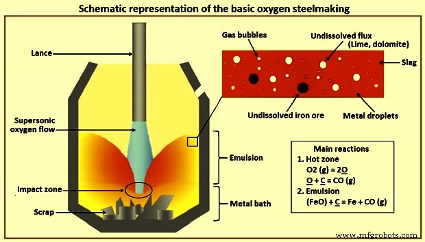
図1基本的な酸素製鋼の概略図
炭素の酸化 –バスで利用可能なCの脱炭は、BOSプロセス中の最も広範囲で重要な反応です。この脱炭反応には3つの異なる段階があります。ブローの最初の数分間に発生する最初の段階では、供給されるO2のほとんどが浴のSiと反応するため、脱炭はゆっくりと行われます。浴の高C含有量で発生する第2段階では、脱炭はより高い速度で行われ、供給されるO2の速度によって制御されます。第三段階は、浴のC含有量が約0.3%に達したときに発生します。この段階では、供給されたすべてのO2と反応するために利用できるCが少ないため、脱炭速度は低下します。この段階では、速度はCの物質移動によって制御され、O2は主に鉄(Fe)と反応してFeOを形成します。この段階では、COの発生率が低下するため、コンバーターの口の炎は発光が少なくなり、Cが約0.1%のレベルに低下すると実質的に消えます。
シリコンの酸化 –シリコンの酸化に適した条件は、(i)低温、および(ii)スラグ中の少量のSiO2です。基本的なスラグはSiの酸化を促進します。塩基性スラグでは、SiO2がCaOと反応し、スラグ中のSiO2の活性を低下させるため、Siの酸化は実際には非常に低い値で発生します。 Siに対するO2の強い親和性のため、ほとんどすべてのSiは、ブローの早い段階で酸化されて除去されます。 HMのSiは、ブローの最初の3分から5分で非常に低いレベル(0.005%未満)に酸化されます。 SiのSiO2への酸化は発熱性であり、かなりの量の熱を発生させ、浴温を上昇させます。また、添加された石灰および焼成ドロマイトと反応して塩基性スラグを形成するケイ酸塩スラグを形成します。 Siの酸化が主な熱源であるため、HMでのその量によって、コンバーターに追加できるコールドチャージ(スクラップ、銑鉄など)の量が決まります。また、スラグの量を決定するため、浴の脱リン酸化と収率に影響を与えます。親指のルールに従って、スラグの量が多いとPは低くなりますが、収量も少なくなります。
鉄の酸化 –鉄(Fe)の酸化は、(i)スラグのFeO含有量と鋼のO2含有量、(ii)スラグ中のFeの損失を制御し、製鋼の生産性に影響を与えるため、BOSプロセスにとって最も重要です。プロセス、(iii)スラグの酸化ポテンシャル、および(iv)FeOはスラグへのCaOの溶解を助けます。
マンガンの酸化 –BOSプロセスでのMn酸化反応はかなり複雑です。トップブローコンバーターでは、ブローの初期段階でMnが酸化されてMnO酸化物になり、ほとんどのSiが酸化された後、Mnはバスメタルに戻ります。最後に、ブローの終わりに酸化に利用できるO2が増えると、Mnはバスメタルで還元されます。コンバーターでのボトムブローまたは複合ブローの場合、Mnの酸化は同様のパターンになりますが、コンバーターバス内の溶鋼の残留Mn含有量はトップブローコンバーターよりも高くなります。
リンの酸化 –コンバーターの酸化条件は、バスメタルの脱リン酸化に有利に働きます。脱リン酸化の反応は、浴中の金属とスラグの相互作用によって起こります。より低い浴温度、より高いスラグ塩基度(CaO / SiO2比)、スラグ中のより高いFeO含有量、より高いスラグ流動性、および浴の良好な攪拌などのパラメーターは、脱リン酸化反応に有利に働きます。バスメタルのリン含有量は、ブローの開始時に減少し、FeOが減少する主な脱炭期間中に、Pはバスメタルに戻り、最後にブロー終了時に再び減少します。浴攪拌は、金属とスラグの混合を改善し、脱リンの速度を助けます。小麦粉スパーなどの流動剤を添加してよく攪拌すると、CaOの溶解が増加し、Pの除去が改善され、非常に塩基性で流動性のある液体スラグが得られます。
硫黄反応 – Sの除去は、酸化性が高いため、BOSプロセスではあまり効果的ではありません。 S分配率(スラグ中の%S /金属中の%S)は約4〜8であり、二次製鋼工程中の鋼取鍋(約300〜500)よりもはるかに低い。 BOSプロセス中、浴中のSの約10%から20%がO2と直接反応して、SO2(二酸化硫黄)を形成します。残りのSは、スラグ-金属反応S + CaO =CaS+FeOによって除去されます。スラグによるSの除去は、スラグの高い塩基度と低いFe含有量によって支援されます。溶鋼のS含有量は、HMに含まれるSと転炉に投入されるスクラップの影響を強く受けます。
BOSプロセス中に発生する反応は不均一で、長さのスケールが異なります。バルク金属浴相、バルクスラグ相、気相があります。一方、反応の多くは、スラグ/金属/ガスのエマルジョン相に分布する微細な液滴や気泡のスケールで発生します。長さスケールの違いは、時間スケールの違いにもなります。金属浴は12分から15分の熱サイクル全体で変化が見られますが、液滴は約1分で精製の完全なサイクルを経ることができます。したがって、プロセスダイナミクスの全体像は、商業プラントとパイロットプラントでの観察と測定、慎重に設計された実験、および数学的モデリングに基づいて、数年にわたって進化してきました。
HMの一般的な組成は、C – 4.5%、Si – 0.3%〜0.5%、Mn – 0.2%〜0.7%、P – 0.1%〜0.18%、S – 0.02%〜0.03%、温度1,350℃です。 。Sは、溶鉄の存在下で還元状態でのみスラグに除去できるため、転炉製鋼の酸化プロセスでは、かなりの量のSは除去されません。重要な全体的な反応は次のように記述できます。 [Si] + {O2} =(SiO2)、(ii)[Mn] + 1/2 {O2} =(MnO)、(iii)[C] + 1/2 {O2} ={CO}、(iv )2 [P] + 5/2 {O2} =(P2O5)、(v)Fe(l)+ 1/2 O2(g)=(FeO)。 [-]、{-}、および(-)は、それぞれ金属浴に溶解したメタロイド、ガス、およびスラグの成分に使用されます。図2aは、200tコンバーターでの反応の進行状況を示しています。さまざまなコンバータで行われた測定でも、同様のパターンが示されています。図2bは、対応するスラグ組成の変化を示しています。
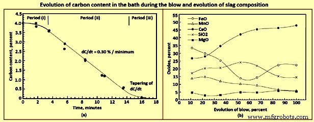
図2ブロー中の浴中の炭素含有量の変化とスラグ組成の変化
金属組成の進化における注目すべき特徴の1つは、Siが非常に低いレベルに低下する前でも、かなりの量のCが同時に除去されることです。これは、CO火炎がO2ブローの開始から短時間でコンバーターの口に放出されるという観察結果によっても裏付けられています。これは、現在廃止されているベッセマーコンバーターまたはOBMプロセスでの観測とは対照的です。このプロセスでは、空気/O2が下から吹き付けられます。これらの2つのプロセスでは、大きな炎の出現に時間がかかります。これは、Siがかなり低い値に低下するまでCの酸化が開始されないことを示していると考えられます。
熱力学的に、上記の入力条件の任意の局所位置での溶質酸化反応の順序は、Si、Mn、C、およびPです。つまり、ブローの最初の部分で一般的な条件では、Siは前に酸化されます。 C.低い初期温度自体が、Si反応を有利にする。さらに、生成物SiO2は、最初から維持されている非常に塩基性の条件では非常に低い活性です。一方、CO分圧はほぼ0.1 MPa(1気圧)のままです。たとえば、SiO2の活性が0.001であると仮定すると、4.5%Cおよび0.5%Siと平衡状態にあるpO2は、それぞれ1MPa〜1.7 MPa、および1MPa〜1.9MPaです。この機能により、プロセスのダイナミクスと反応メカニズムの分析が興味深いものになります。
プロセスの特徴
プロセスからのフィードバック情報は限られているため、取得できる情報から観察された特性からプロセスダイナミクスのモデルを構築する必要があります。 BOSプロセスの重要な機能を以下に説明します。
反応速度は非常に速いです。脱炭のピーク時には、Cは毎分約0.3%の割合で除去されます。つまり、200 tコンバーターでは毎分約600kgのCが除去されます(図2a)。 C反応は3つの典型的な期間(図2a)を示します。すなわち、(i)速度が増加している初期期間、(ii)浴中のC含有量が継続的であるにもかかわらず、速度が比較的一定である中間期間です。この期間中は約3.5%から4.0%に低下し、レートが低下すると、最後の3番目の期間はクリティカルCコンテンツを超えます。臨界C含有量は通常0.2%から0.5%の範囲にあります。
ただし、同じブロー条件での個々の熱は、広い再現性を示します。同一の入力とプロセスパラメータを使用した2回の連続ブローは、まったく異なる動作を示す可能性があり、一部のブローでは、スロップ(コンバータの口で沸騰する金属スラグガスエマルジョン)または乾燥スラグと唾吐き(ランスと口の蓄積をもたらす)が表示されます。 。攪拌ガスのボトムブローがまだ組み込まれていなかったBOSプロセスの初期には、再現性がないことがはるかに一般的でした。クーラントとして使用するスクラップを減らすことで、再現性を高め、スロップを減らすこともできます。
いくつかのBOSショップを調査した結果、脱炭のピーク速度はO2の吹き込み速度に正比例することが示されました。実験室サイズのコンバーターでのブロー中に、O2ブローレートの増加率とランス高さの減少がピーク脱炭率に及ぼす影響も同様であることが示されています。
MEFOS(スウェーデンの研究所)でのパイロットコンバーターでの実験中に、トップブローコンバーターの高さに沿って濃度変動があることが示されました。これは、トップジェットの勢いが非常に大きいにもかかわらず、トップブローが金属浴をうまく混合していないことを示しています。しかし、この違いは、非常に少量の不活性ガスを底から吹き付けることで消えました。
BOSプロセスのスラグには、スラグ相の液滴の形で金属のかなりの部分が含まれていることはよく知られています。量は打撃中に変化し、打撃の中間部分で最も高くなります。見積もりは10%から25%の範囲で異なります。これらの液滴は非常に細かく、ほとんどが1mmから2mm未満です。エマルジョン中の液滴の数は、ブローの終わりに向かって減少します。液滴は通常、バルク金属浴と比較してはるかに高度な精製状態にあります。
ほとんどの打撃の間、スラグ-金属-ガスエマルジョンが存在します。打撃の約3分の1までに、乳剤の高さが約2 mを超えるため、ランスの先端が沈み、超音速ジェットの音がミュートされます。時々、エマルジョンは炉全体を満たし、口の中で沸騰する(傾斜する)ことがあります。浴中の臨界Cを超える打撃の終わりに向かって、エマルジョンは崩壊し、エマルジョンが一時的であり、その生存のために継続的なガス生成を必要としていることを示します。
述べたように、C、Mn、およびPは、ブローの最初の部分でSiと同時に酸化されますが、バルク金属浴の組成に基づく他の反応よりもSi反応が優先されると予想されます。 MnとPの反応は、スラグでの活動の事実によってある程度説明することができます。バルク金属組成が反応部位で優勢ではないという仮説を使用しない限り、C反応を説明することはできません。
打撃の途中でMnとPが反転します(図3a)。これはスラグパスにも反映されます(図2b)。ただし、復帰がスラグ中のFeO含有量と相関していることは明らかです。 CaOの溶解は、打撃の最初または初期に石灰が添加されたにもかかわらず、ほぼ最後まで続きます。 Cはプロセスの全体的なダイナミクスを決定し、この反応は活発に行われます。図3aは、ブロー中の溶融組成の変化を示しています。
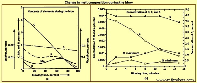
図3ブロー中の溶融組成の変化
BOSプロセスのダイナミクスは、激しく発生するC反応に依存します。完全なダイナミクスは、いくつかのサイトに分割できます。このフレームワークでは、他の反応を理解できます。 O2ジェットはほぼ純粋であり、分子はかなりの物質移動障壁なしに直接浴表面に到達します。分子が衝突すると、次のいずれかを実行できます。
O2分子は衝撃部位でCと反応します。反応は、[C] + 1/2 {O2} ={CO}、および[C] + {O2}={CO2}になります。 [O]として金属に溶解することができます。その後、これは他の場所に移動し、O2 =2[O]などの他の酸化可能な元素と反応する可能性があります。その一部は、式Fe + 1/2 {O2} =(FeO)のように、浴中でFeと反応してFeOを生成します。 FeOはスラグ相に移動し、他の場所で金属と反応する可能性があります。これらのそれぞれが、コンバーター内のさまざまな可能な場所で行われる精製反応につながり、混合時に、全体的な浴の精製につながります。これらの異なるサイトを図4に模式的に示します。
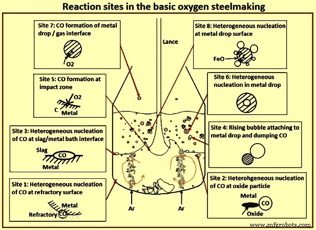
図4転炉の反応サイト
C-O反応は不均一であることに注意してください。速度を制限する可能性のある物質移動ステップが少なくとも1つあります。 Cは金属内で界面に拡散する必要があります。反応のO2源によっては、気相でのO2、金属相での溶解O2、またはスラグ相でのFeOの移動も関与する可能性があります。溶解したO2は、金属浴内の他の部分に移動し、溶解したCと反応して、耐火物のガスで満たされた細孔にCOを放出します(サイト1)。 COは、不均一な核形成によって金属浴に浮遊する固体粒子上にも形成される可能性があります(サイト2)。不均一核生成は、スラグ層/金属浴界面(サイト3)でも発生する可能性があります。 CO過飽和が非常に高くない限り、浴内での均一な核形成はほとんどあり得ません。前述のように、CO反応は衝撃サイト(サイト5)で直接発生する可能性があります。衝撃サイトまたはその近くで形成されたFeOの一部は、金属浴表面の下に入り、スラグ/金属界面に沿って移動し、Cと反応して乳化界面を生成します(サイト3の場合と同様)。ただし、形成されたFeOの大部分はおそらくスラグ相に移行します。
これにより、いくつかの可能性が生まれます。スラグと金属浴の間の界面では、前述のように反応が起こる可能性があり(サイト3)、O2はスラグ相から、Cは金属から発生します。前述のように、スラグ相には多数の金属液滴が含まれており、衝突部位でのジェットの運動量によって連続的に生成されます。したがって、スラグ中のFeOは、次のようなさまざまなメカニズムを介してこれらの液滴と反応することができます。液滴(サイト4)、および(iii)過飽和が非常に高い場合(サイト6)、COバブルは液滴内で均一に核形成する可能性があります。金属の液滴がフリーボードに投げ込まれると、ガス中のO2またはCO2と直接反応する可能性があります(サイト7)。
これらのサイトはすべて、打撃中にある程度アクティブになる可能性がありますが、全体的なダイナミクスを決定する主要なメカニズムを特定する必要があります。これらの各サイトからの貢献は、観察に基づいて評価できます。下部ガス注入がない場合に浴が濃度勾配を示すという事実は、上部ガス流と比較して、わずか1%の不活性ガスが下部から吹き出されることで消失します。サイト1とサイト2のメカニズム重要ではないとして割引することができます。
衝撃ゾーンの表面の温度は2,120℃を超えると予想されます。したがって、化学反応の速度は非常に速いと予想されます。衝突地点の面積は比較的小さく、O2の到達率は非常に高い。ただし、溶質は界面に拡散する必要があり、熱は金属に伝導する必要があります。新鮮な金属は、大きな表面速度によって外側に掃引される界面に運ばれます。このような状況では、衝撃面で溶質が不足し、O2と反応するFeの層が残っていることが予想されます。最終的に、バルク金属組成の金属層が完全に酸化され、凝縮相酸化物がスラグ層に移動すると仮定することは合理的である可能性があります。 C含有量が約5%(20〜25 mol%)の場合、この概算は、供給されたO2の約25%がこのサイトでC(COおよびCO2)に消費されることを意味します。金属側の物質移動が速度制御ではないと仮定した計算に基づいて、寄与は約40%と推定されます。かつては、それが主要なメカニズム(ホットゾーンまたはインパクトゾーン理論)であると考えられていました。このサイトで外側に流れる金属層も、前述のようにO2で飽和する可能性があります。
エマルジョンの反応には、反応の主要なサイト(サイト4、6、および8)が含まれているようです。エマルジョン中の液滴は、比表面積が非常に大きい。スラグ中に適度な量のFeOが存在する場合、液滴内のすべての精製反応は、数分ではなく数十秒で発生する可能性があります。 4.5%のCを含む3 mmの金属滴は、その体積の約3,000倍のCOを発生させる可能性があります。これは、粘性のあるスラグから逃げるときに乳化します。したがって、エマルジョン形成、液滴生成、液滴滞留時間などの複雑な相互作用は、全体的なダイナミクスに大きく貢献します。気相と直接反応する液滴の反応は、完全なスラグ層がまだ形成されていない場合、主に打撃の最初の数分間で重要です。
この全体的なプロセスダイナミクスを包括的に見るには、超音速ガスジェット、金属/スラグ浴との相互作用、液滴の生成と滞留時間、CaO溶解、浴混合などの背景が必要です。
ガスインガスジェットは、その周辺に周囲ガスを同伴します。乱れた層は、ジェット軸の数ノズル直径下流(潜在的なコア領域)に到達し、それを超えると、流れは自己相似の視線速度プロファイルで完全に発達します。運動量保存則を維持するために、軸方向速度は距離に反比例して変化します。通常、周囲のガスの密度がジェットガスの密度と同じである場合、ジェットは約10度から12度の角度の半円錐で膨張します。周囲が軽い場合、質量効果による膨張は少なくなります。
超音速ジェットでは、圧縮率がジェットの膨張に影響します。軸方向速度が音速まで減速するまでジェットはあまり膨張しないことが示されています(超音速コア)。その後、ジェットは図5に示すように亜音速ジェットとして膨張します。BOSコンバーターへのO2ジェットの最近のCFD(計算流体力学)研究は、軸方向速度が約1mの距離とこの領域では、軸のガスは約-170℃のままです。その後、高温ガスの同伴により温度が着実に上昇します。したがって、O2ランスは、出口マッハ数が約2で動作するため、ある程度の距離を保ちながら、ジェットと金属の相互作用を良好に保つことができます。
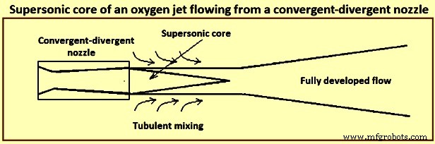
図5収束-発散ノズルから流れる酸素ジェットの超音速コア
BOSコンバーターのようにO2ジェットをCOの雰囲気に沈めると、O2の濃度が大幅に低下する可能性があることに注意してください。
高速ジェットが金属表面に当たるとクレーターが形成され、偏向ジェットの速度が速いためにエッジが非常に不安定になり、金属液滴が放出されます。十分に高い値では、ジェットはリエントラントになり、液滴の一部がジェット自体に投げ込まれ、非常に不安定なクレーターが振動して回転します。 In the presence of a slag layer these droplets are trapped by the slag leading to droplet-in-slag emulsion.
The crater depth can be calculated by performing a momentum balance at the stagnation point at the centre of the crater. In further studies with a constant based on the experiments with various liquids and gases at room temperature and quantitatively studying the emulsification phenomena with the help of a 2-dimension, two phase model of mercury and glycerol, it has been found, as expected, that the droplets in the emulsion are increased with gas flow rate and varies inversely with stand-off distance of the lance tip from the liquid surface (lance height). While experimenting with a 3-dimension model of water to determine the droplet generation rate with a top layer representing slag, it has been found that there are two regions, one at a lower flow rate where the rate increases nonlinearly with flow rate and the second where the rate varies almost linearly with the flow rate. The Weber number has been used to characterize the flow phenomena. Droplet generation rate (kg/second) is correlated experimentally as a function of the blow number. It has been shown that simultaneous bottom gas injection can increase droplet generation especially when they are nearly coaxial with the top jet. The presence of slag phase can change the rate of generation substantially.
In a supersonic jet, say of Mach 2, the exit gas temperature is around -100 deg C. Thereafter, it entrains lower density converter gas. The temperature, velocity, and composition of the gas change as the jet strikes the bath. Hence this correlation has large uncertainties, because of which usefulness of the correlation in the BOS model is less than adequate. Since there is no other correlation, one normally uses the above correlation for generation of droplets and tunes it as needed.
The reaction rates also depend on the droplet sizes. Several studies have obtained emulsion samples from the working converters or laboratory hot models. These studies have found in general the sizes to be in the range of 0.05 mm to 3 mm. In a study experimenting with pig iron and O2, there were large chunks of liquids thrown out, which normally spend negligible quantity of time in the emulsion. Though these approximations and correlations are clearly inadequate, most models use these for lack of better correlations.
One of the studies found large quantities of metallic droplets in the foamy slag formed during high P iron refining. Another study made similar observations by collecting samples ejected through the tap hole in a 230 t converter and analyzing them. Several other studies have also made similar observation.
As mentioned earlier, the droplets are in various states of advanced refining, some of them being almost completely refined, though the bath still had considerable quantity of C. The fraction of metal in the emulsion has been estimated to be large, being almost 25 % of the bath weight. This corresponds to a surface area of around 40,000 square metres (sqm) if one assumes an average size of 1 mm for the droplets. It has been proposed in one of the studies that refining in the converter takes place primarily in the emulsion phase, the bath seeing refining by dilution from droplets falling back (emulsion theory). Emulsion in the converters refers to a slag-metal-gas system. One can visualize it as slag-gas foam in which metal droplets are distributed.
It has been also reported that several of the droplets display high O2 super-saturation and this has postulated that the finer droplets can have been generated by homogeneous nucleation of CO droplet bursting. Some droplets show evidences of being attached to gas bubbles and some are even hollow. There have been several experiments with magnetically levitated and freely falling droplets reacting with oxidizing gases. The results of these experiments are interesting. When the C content is high, one can see reactions taking place at the surface, as evidenced by CO burning. As the C content comes down, small droplets are thrown out indicating sub-surface nucleation. Further lower in C content, the droplets sometimes burst, indicating O2 super-saturation and nucleation deep within the droplet. Super-saturation to the extent of around 5 MPa (for equilibrium CO) had been reported at the time of droplet bursting.
In one of the studies, the residence time of the droplets in a converter has been measured by radioactive gold isotope tracer technique. The maximum residence time of droplets which are in advanced state of decarburization has been estimated to be around 2 minutes. Residence time calculated on the basis of free fall is of the order of a few seconds even while considering the slag to be emulsified to a much greater height. The high residence time hence needs an explanation.
Several experiments using X-rays for visualization of a single Fe-C droplet reacting in molten oxidizing slags have shown that the droplet gets buoyed up to the surface as soon as decarburization starts, and stays at the surface till the CO bubbling subsides. Further, it has been shown that the droplet residence time is dependent on bubble formation which keeps the droplet afloat.
There are two views on how the CO formation keeps the droplet buoyant. One of the studies has formulated a bloated droplet theory wherein CO forms homogeneously inside the droplet and this hollow droplet has a low apparent density, due to which it remains afloat. The other view is that the bubbles form heterogeneously at the droplet / slag interface and as long as the bubbles stay attached to the droplet they keep it afloat. The visual evidences from X-ray fluoroscopic studies cannot clearly distinguish between these two. The fact that there does not seem to be a nucleation barrier during vigorous deoxidation as evidenced by copious evolution of bubbles suggests interface nucleation.
At high C concentrations when C mass transfer within the drop is not rate controlling, the highest CO super-saturation is to be seen at the droplet surface. Hence, it can be expected that for the nucleation to take place heterogeneously at the surface, the bubble is to spend some time at the interface before detaching. Since there can be several bubbles attached, the droplet remains buoyed. As C falls to low values, nucleation at the interface becomes sporadic, and in periods when there is no bubble attached, O2 dissolves into the metal and diffuses in. Hence, the highest super-saturation region moves inward, first to sub-surface and then to deep inside the droplet. One can thus see sub-surface nucleation initially throwing out small droplets and then deep inside. These homogeneous nucleation events are probably sporadic, with a stochastic nature.
Simultaneously, the apparent density of the droplet with no or few bubbles is now high and it falls down into the metal bath. The critical C content when the droplet falls down depends on droplet size, the oxidizing potential of the slag (and the rate of mass transfer of FeO), and the sporadic nucleation event either at the surface or inside the droplet. Empirical work to correctly predict the critical C content is lacking. Evidence from levitated droplet experiments also point towards these series of events, though the stirring due to the electro-magnetic field makes the condition different from that in the converter especially with respect to mass transfer within the droplet.
In the context of converter, the droplet surface is continuously disturbed by the bubbles. This has two counteracting effects. Part of the droplet surface is covered by the gas bubble and is not available for mass transfer from the slag to the droplet. The droplet surface is also vigorously stirred by the formation and detachment of bubbles, enhancing mass transfer locally. Several indirect estimations have been made. In one of the studies, indirect estimation of mass transfer coefficient has been made for FeO in slag for P transfer rate in high temperature single droplet experiments, and the values obtained are between (10)−5 metres per second (m/s) and (10)−4 m/s . Another study estimated similar values. Proper experimental studies, both in cold and hot models, are necessary to get reasonable correlations in terms of dimensionless variables.
Though the slag is very well stirred in the converter due to the gas jet and a large quantity of gas passing through it, the metal bath in top blown converters is comparatively poorly mixed. Measurement of mixing time (t95 which is the time to get 95 % homogeneity) in top blown converter can be as high as 150 seconds (s) to 180 s, as compared with 10 s to 20 s in bottom blown OBM converters. This has consequence on the reaction dynamics, since the metal droplets are removed from the top layer and the refined droplets from the emulsion fall back at the top. Since much of the heat is also released in the slag, the slag and the droplets falling back are also hotter. There can also be composition and temperature stratification due to the scrap at the bottom slowly dissolving into the liquid metal.
High mixing times also correspond to high irreproducibility in mixing times, leading to irreproducible blow behaviour in the absence of bottom blowing. For example, a large eddy of liquid metal containing higher C from the bottom being brought to the surface of the metal bath can suddenly increase the rate of decarburization leading to instabilities. Hence, inert gas injection from the bottom of the converters to bring down the mixing time has become the standard practice.
Since the rate of bottom gas injection and the position of the porous elements through which the gas is introduced have a bearing on the reaction dynamics, it is necessary to quantify the mixing behaviour for quantitative predictions of composition and temperature evolution. A single average t95 value is inadequate for incorporation into a comprehensive model of the converter, since two different mixing curves can give the similar t90 (time to get 90 % homogeneity) and different t95 values. The compromise can hence be a two parameter model, based on estimation of two mixing times (t90 and t95). One can then idealize the metal bath as consisting of two stirred tank reactors (STR), exchanging metal continuously. The bottom part sees only scrap melting and the top part sees all other phenomena explained earlier. The two parameters of this model, ratio of reactor sizes and the metal exchange rate can then be fitted to the mixing times of the converter under various conditions of operation.
Formation of slag and dissolution of fluxes
Fluxes (lime and calcined dolomite) which are charged early in the blow dissolve with the developing oxides to form a liquid slag. The rate of dissolution of these fluxes strongly affects the slag-metal reactions occuring during the blow. At the beginning of the blow, the lance height above the bath is kept high which causes an initial slag rich in SiO2 and FeO. During this period large quantities of fluxes are charged in the converter. The lance is then lowered and the slag starts to foam at around one third of the blow due to the reduction of FeO in the slag in conjunction with CO formation. As the blow progresses, the CaO dissolves in the slag, and the active slag weight increases. After the blow has progressed around three fourth of the time, the FeO content in the slag increases because of a decrease in the rate of decarburization.
During the blow, the temperature of the liquid steel gradually increases from around 1,350 deg C to 1.650 deg C at turndown of the converter, and the slag temperature is around 50 deg C higher than that of the liquid steel. The slag at turndown can contain regions of undissolved lime mixed with the liquid slag, since the dissolution of lime is limited by the presence of dicalcium silicate (2CaO.SiO2) coating, which is solid at steelmaking temperatures and prevents rapid dissolution. The presence of MgO in the flux weakens this coating. Hence, earlier charging of MgO speeds up slag formation due to quicker solution of lime.
The converter needs to maintain a good fluid slag of high basicity (high CaO content) so that the large quantity of CO generated can be handled, and P can be removed efficiently. Hence, the converter operator tries to achieve a CaO / SiO2 ratio in excess of 3.0 in the final slag.
Fig 6a shows the liquidus contours in a CaO-SiO2-FeO ternary diagram. It is clearly seen that a CaO / SiO2 ratio which can be achieved in this system at 1,350 deg C, i.e. at the beginning of a blow this ratio is limited to around 1.6 to 1.7. Marginal improvement can take place with MgO additions (Fig 6b) and some Al2O3 coming from the carry over slag. In the final slag also at 1,650 deg C with 25 % to 30 % FeO, the maximum CaO / SiO2 remain less than 3.0. This is also borne out by the slag analyses which frequently show un-dissolved lime. Apart from the issue of solubility of CaO in the converter slags, the lime particles get passivated in the presence of highly siliceous slags. Since the CaO concentration is the highest at the surface of a dissolving lime particle, di-calcium silicate forms here. This compound is not only highly refractory but it forms an adherent layer retarding further dissolution.
A lime particle remaining undissolved for long at the high temperatures also sinters and becomes less reactive. One way of breaking the adherent layer is to have high FeO content in the slag. This is the reason for the practice of raised lance blowing in the first few minutes of the blow, when the FeO is built up to 25 % to 35 % or higher. Though the effect on solubility of CaO is marginal (Fig 6), this facilitates breaking of the adherent di-calcium silicate layer permitting further dissolution.
Additives like fluorspar (CaF2) can bring about this effect much more efficiently, though this is not an acceptable plant practice in recent times for various reasons. Fig 6 shows phase diagrams with Fig 6a showing liquidus isotherms of CaO-SiO2-FeO system and Fig 6b showing tffect of MgO addition on the liquidus.
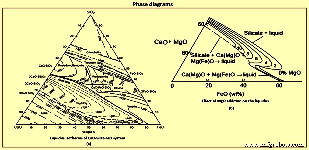
Fig 6 Phase diagrams
Process flow and reaction dynamics
The contents of the converter can be divided into several important regions such as (i) the metal bath, which itself can be divided into the bottom and top part between which there is exchange of metal, (ii) the O2 jet and the impact region, and (iii) the slag region which mostly is in the form of a slag-metal-gas emulsion. There are three distinct regimes in the blow. The initial part is characterized by a bare metal bath covered with islands of solid lime and some slag carried over from the previous heat. Jet of O2 hits the metal bath and does two primary things. First, it oxidizes almost an entire layer of the metal giving CO, SiO2, MnO, P2O5 and lots of FeO. Not all O2 is consumed in this location, and the gas above hence can contain high ratio of CO2 / CO and some O2 as seen in exhaust gas analysis. The jet also throws droplets into the gas phase, which after free flight fall back. Since the gas is oxidizing, the droplets get refined during the flight. At the surface of the droplets, the order of reactions is dictated by the thermodynamics.
For each of the solutes, reaction involves mass transfer steps such as mass transfer of CO2 / O2 in the gas phase and of the solutes in the liquid phase. The interfacial chemical reactions are expected to be very fast at this temperature. The order of the reactions can be achieved by solving the mass transfer equations along with free energy minimization for the interface reactions competing for O2. The order is normally Si and Mn followed by C and P. Since the time of flight is typically of the order of a second or lower, the droplets fall back probably completing only part of the Si reaction. Smaller the droplet, further the refining proceeds because of the larger specific surface area. Reaction at the rest of the surface of the metal bath is small because of the smaller surface area compared to that of the droplets.
The mass transfer in the gas phase can easily be calculated by Ranz-Marshall type correlations. At this initial phase of the process droplets are high in solutes, and the gas phase mass transfer is expected to be rate controlling. The small droplets can be considered as rigid and one can assume pure diffusion of solutes inside the droplets. When the droplets fall back, the condensed phase oxide products in the droplets remain at the top of the bath, and on combining with the oxides from the impact site and the fluxes added start forming a liquid slag. As mentioned earlier, good quantity of FeO is formed at the impact site, and hence liquid slag formation is easy. After sometime, there is a liquid slag layer covering the metal bath. Increasingly more and more droplets are thrown to the slag. The droplets ejected into the gas phase now have to pass through the slag phase before reaching the metal bath. Further refining hence takes place in the slag.
Initially when the slag layer is thin and the droplets are high enough in Si and Mn, the droplets fall through before the C reaction starts, that is, with no gas evolution, especially for larger droplets. Smaller droplets high in C can however start to decarburize early releasing CO, and slowly emulsifying the slag. This early phase is characterized by a low flame at the mouth, since CO formation is comparatively low. Once the Si in the metal bath falls down to some extent, the desiliconization progresses considerably, before the droplet has fallen down. C reaction starts and the droplet stays now buoyed in the emulsion till its C content reaches the critical C content as explained earlier. In the slag phase, the rate is expected to be controlled by slag phase mass transfer of FeO, as long as C in the droplet remains high enough. Once a critical C is reached in the droplet, bubbling slows down and then ceases, and the droplet falls down. The critical C is largely determined by the FeO content in the bath. Quickly the emulsion builds up and the second phase of reactions in the emulsion starts. The flame at the converter mouth becomes large. The lance tip gets dipped into the emulsion.
In the second phase almost all of the droplets are ejected into the emulsion, and the gas phase reactions become unimportant. It is to be noted that the residence times of the quiescent droplets in the slag are only of the order of a few seconds unless decarburization reaction starts. Hence, for maximizing the refining, the operator is to quickly reach a stage where the decarburization reaction starts before the droplets fall back. One way to accelerate the reactions is to keep the FeO content in the slag high. Another reason why FeO is to be increased as early as possible is to have a fluid slag by the time decarburization rate reaches its highest value, since the large quantity of gasses are to quickly escape from the slag. Else, the emulsion height gets build up uncontrollably leading to overflow, and slopping.
The FeO content in the slag is a balance between its generation at the point of impact and its consumption by the droplets in the emulsion. The FeO generation is probably weakly dependent of the lance height, whereas a high lance leads to less droplet generation due to lower force with which the jet strikes the metal bath, and vice versa. Hence a raised lance practice, called the soft blow, leads to quick increase in the FeO content in the slag. This facilitates CaO dissolution and formation of a fluid slag. The initial soft blow, normally 3 min to 4 min, is the normal plant practice.
At an optimum moment, the lance is lowered to induce high rates of reactions. Droplet generation rates are high, the bath is already desiliconized, and hence the droplets undergo vigorous decarburization till C goes to low values before falling back. During this period of peak decarburization rates, hence a large part of the metal bath remains in the emulsion as droplets. These droplets have spent different times in the emulsion and hence are in different stages of refinement. The degree of refinement also depends on the droplet size. The droplet are hence characterized by two variables namely the time it has been formed (and hence its age) and the size of the droplet. The droplet starts to fall back when a characteristic C content is reached, which depends on its size, the slag FeO, and the temperature. During this last phase of the droplets, the O2 potential at the interface is also high and hence P is also removed if other conditions are favourable. Falling droplets result in apparent refinement of the top of the metal bath, which on mixing lead to refinement of the rest of the bath. Since the time for refinement of a droplet can be of the order of 0.5 min to 2 min, one sees drop in C, Mn and P in the bulk metal sample even if Si in the sample is still of considerable quantity (Fig 3a).
The overall rate of reaction, to some extent, is self-correcting. If the number of droplets in the emulsion come down decreasing the rate, the level of the metal bath increases leading to lower effective lance distance, which in turn causes droplet generation to increase. This is one of the reasons for the near constant decarburization rate during middle part of the blow. It is however is to be noted that the C content of droplets entering into the emulsion keeps falling down, and hence their residence time. The operator is required to correspondingly increase the droplet generation rate by progressively lowering the lance. Fig 7a indicates the lance height variation during a typical blow.
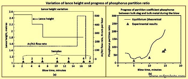
Fig 7 Variation of lance height and progress of phosphorus partition ratio
As the bath becomes low in C in the final phase of the blow, the rate now gets limited by C diffusion within the droplet even as it enters the emulsion. The CO generation is low and is not able to keep the droplets floated. The residence time drops down to a few seconds, and hence number of droplets in the emulsion comes down even though the lance height has been brought down to the lowest level permissible for lance health. The emulsion dies down. At this time there is falling rates of decarburization and fast buildup of FeO in the slag. Since the rates are low, the FeO content and the O2 dissolved in steel increase much beyond what is dictated by C-O equilibrium. Hence, at this period, the operator raises the argon stirring rate, increasing thereby the droplet generation rate without adding extra O2. This helps to some extent.
Phosphorus removal is sometimes an issue in the BOS process and can result in re-blows, especially when the input P in the hot metal is high (around 0.2 %). Though the conditions are normally favourable in the final slag with high FeO and high basicity, the converter operator can land in adverse situation if the slag regime is not carefully managed throughout the blow. The thermodynamics of P is well known. The reaction is written either in terms of molecular species or in the ionic form. The reaction is 2P + 5/2 O2(g) =P2O5(l), P + 5/4 O2(g) + 3/2 (O)2− =(PO4)3−. In the former case one writes an equilibrium constant, and expresses the Raoultian activity coefficient as a function of slag composition. If one adopts an ionic form of the equation, one instead writes an equation for a phosphate capacity of slag and correlates the phosphate capacity to the slag composition empirically. Both these approaches are conceptually similar. The partial pressures of P and O2 can easily be converted to percent dissolved in metal or activity of FeO in slag with known thermodynamic data. The slag data as a function of composition either as Raoultian activity coefficient or as phosphate capacity have been empirically determined in several studies. The progress of partition coefficient for P between bulk slag and bulk metal can be calculated when the slag analysis during the blow is known.
In the initial period of the blow, the bath C is quite high and also contains Si. Hence at the slag / metal interface, the O2 potential remains low. Therefore, very high rate of dephosphorization at the bulk metal / slag interface is not expected. The metal droplets, on the other hand, get highly refined in a matter of 1 min to 2 min, and before returning to the metal bath, have high O2 potential at its interface. Further the partition coefficient at this time is high since FeO content is high due to soft blow, temperature is low, although with some CaO yet to dissolve. The number of droplets in the emulsion is also very large. Hence, the dephosphorization rate is very high which can be seen in Fig 3a. Towards the end of the blow again, the conditions in the slag are favourable with high FeO and high basicity, though now the temperature has risen substantially. The rate of phosphorus removal however is not very high in this period, since the number of droplets is not very high, surface area is quite small and hence all reactions are slow.
Vigorous Ar stirring is helpful at this time of the blow, and for some time after the O2 flow is stopped, though to a limited extent. It is in the middle part of the blow the operator has the highest opportunity for efficient overall dephosphorization. After the soft blow when the lance is lowered progressively for effecting high rates of decarburization, FeO content in the slag drops considerably and remains low till the emulsion starts collapsing. The slag becomes comparatively ‘dry.’ The partition coefficient becomes adverse, and one can easily get P reversal to the metal. Lower is the FeO level, higher is the reversal. This reversal increases the load on the last part of the blow where the rates of reactions are anyway low as explained earlier.
Hence, close control of the FeO content during the middle part of the blow is necessary if the operator is required to make low P steel. Premature lowering of the lance in each stage can lead to very low FeO content (less than 12 % to 15 %). FeO content is determined by the balance between droplet generation rate (consumption rate) and the FeO generation rate. However, it is to be noted that very low FeO in the slag also lowers the decarbonization rate. Very high FeO on the other hand leads to sloppy conditions.
Higher levels of FeO content can be achieved by modifying the lance practice. The lance height for the intermediate levels can be kept slightly higher than the normal. The operator can also slightly delay lowering of the lance, taking care to see that it does not lead to uncontrolled emulsion build up. The operator can also achieve this by distributed ore addition during this period.
The chemistry of steelmaking in BOS converter is summarized here. From the thermodynamics of the O2 steelmaking process, it can be seen that, at the beginning, the O2 blown onto the HM preferably reacts with the dissolved Si, forming SiO2 which floats on the surface of the metal. From kinetics, it is expected that a part of the O2 blown reacts with the dissolved C and Fe atoms. The formation of CO gas occurs instantaneously on process ignition. Calcined lime is added to neutralize the acid slag, which initially includes a liquid mixture of FexOy and SiO2. Several chemical reactions take place in the BOS converter. The main reactions are dissolution of O2 into the metal from O2 gas, decarburization through dissolved O2, and oxidation of Fe, [Si], [Mn], [P], [V] and [Ti]. Solid or liquid oxides are formed as reaction products during blowing, and they are bound with the lime which is added at the start of blowing to form a liquid slag in the converter. Due to intensive CO gas formation, droplets of liquid metal are introduced into the slag, which tends to foam. Hence, the slag in the converter during O2 blowing is actually an emulsion of liquid slag and metal droplets, foaming because of the influence of gas bubbles. The emulsion is also a favourable site for reactions. For example, a considerable fraction of C oxidation can occur in the metal droplets in the emulsion although the majority takes place in the impact zone of the O2 jets. The rest of the O2 is used to burn Fe into FexOy. During blowing, O2 penetrates the metal droplets and can react with the CO gas. The total slag-gas system behaves as foam and rises quickly to the cone of the converter. Hence, the O2 inflow and the reaction rates have to be adjusted so that foam is not spilled from the converter. Slopping frequently occurs even though the inner volume of the converter is almost nine times larger than the volume of the inactive metal and slag bath.
製造プロセス